EP2671755A1 - Lighting device comprising an array of optoelectronic sources - Google Patents
Lighting device comprising an array of optoelectronic sources Download PDFInfo
- Publication number
- EP2671755A1 EP2671755A1 EP13167053.1A EP13167053A EP2671755A1 EP 2671755 A1 EP2671755 A1 EP 2671755A1 EP 13167053 A EP13167053 A EP 13167053A EP 2671755 A1 EP2671755 A1 EP 2671755A1
- Authority
- EP
- European Patent Office
- Prior art keywords
- lighting device
- reflector
- sources
- array
- reflective surface
- Prior art date
- Legal status (The legal status is an assumption and is not a legal conclusion. Google has not performed a legal analysis and makes no representation as to the accuracy of the status listed.)
- Granted
Links
Images


Classifications
-
- F—MECHANICAL ENGINEERING; LIGHTING; HEATING; WEAPONS; BLASTING
- F21—LIGHTING
- F21S—NON-PORTABLE LIGHTING DEVICES; SYSTEMS THEREOF; VEHICLE LIGHTING DEVICES SPECIALLY ADAPTED FOR VEHICLE EXTERIORS
- F21S43/00—Signalling devices specially adapted for vehicle exteriors, e.g. brake lamps, direction indicator lights or reversing lights
- F21S43/10—Signalling devices specially adapted for vehicle exteriors, e.g. brake lamps, direction indicator lights or reversing lights characterised by the light source
- F21S43/13—Signalling devices specially adapted for vehicle exteriors, e.g. brake lamps, direction indicator lights or reversing lights characterised by the light source characterised by the type of light source
- F21S43/14—Light emitting diodes [LED]
-
- B—PERFORMING OPERATIONS; TRANSPORTING
- B63—SHIPS OR OTHER WATERBORNE VESSELS; RELATED EQUIPMENT
- B63B—SHIPS OR OTHER WATERBORNE VESSELS; EQUIPMENT FOR SHIPPING
- B63B51/00—Marking of navigation route
- B63B51/02—Marking of navigation route with anchored lightships; by use of lighthouses
-
- F—MECHANICAL ENGINEERING; LIGHTING; HEATING; WEAPONS; BLASTING
- F21—LIGHTING
- F21S—NON-PORTABLE LIGHTING DEVICES; SYSTEMS THEREOF; VEHICLE LIGHTING DEVICES SPECIALLY ADAPTED FOR VEHICLE EXTERIORS
- F21S43/00—Signalling devices specially adapted for vehicle exteriors, e.g. brake lamps, direction indicator lights or reversing lights
- F21S43/30—Signalling devices specially adapted for vehicle exteriors, e.g. brake lamps, direction indicator lights or reversing lights characterised by reflectors
-
- F—MECHANICAL ENGINEERING; LIGHTING; HEATING; WEAPONS; BLASTING
- F21—LIGHTING
- F21V—FUNCTIONAL FEATURES OR DETAILS OF LIGHTING DEVICES OR SYSTEMS THEREOF; STRUCTURAL COMBINATIONS OF LIGHTING DEVICES WITH OTHER ARTICLES, NOT OTHERWISE PROVIDED FOR
- F21V7/00—Reflectors for light sources
-
- F—MECHANICAL ENGINEERING; LIGHTING; HEATING; WEAPONS; BLASTING
- F21—LIGHTING
- F21V—FUNCTIONAL FEATURES OR DETAILS OF LIGHTING DEVICES OR SYSTEMS THEREOF; STRUCTURAL COMBINATIONS OF LIGHTING DEVICES WITH OTHER ARTICLES, NOT OTHERWISE PROVIDED FOR
- F21V7/00—Reflectors for light sources
- F21V7/0025—Combination of two or more reflectors for a single light source
- F21V7/0033—Combination of two or more reflectors for a single light source with successive reflections from one reflector to the next or following
-
- F—MECHANICAL ENGINEERING; LIGHTING; HEATING; WEAPONS; BLASTING
- F21—LIGHTING
- F21V—FUNCTIONAL FEATURES OR DETAILS OF LIGHTING DEVICES OR SYSTEMS THEREOF; STRUCTURAL COMBINATIONS OF LIGHTING DEVICES WITH OTHER ARTICLES, NOT OTHERWISE PROVIDED FOR
- F21V7/00—Reflectors for light sources
- F21V7/04—Optical design
- F21V7/041—Optical design with conical or pyramidal surface
-
- F—MECHANICAL ENGINEERING; LIGHTING; HEATING; WEAPONS; BLASTING
- F21—LIGHTING
- F21V—FUNCTIONAL FEATURES OR DETAILS OF LIGHTING DEVICES OR SYSTEMS THEREOF; STRUCTURAL COMBINATIONS OF LIGHTING DEVICES WITH OTHER ARTICLES, NOT OTHERWISE PROVIDED FOR
- F21V7/00—Reflectors for light sources
- F21V7/04—Optical design
- F21V7/045—Optical design with spherical surface
-
- F—MECHANICAL ENGINEERING; LIGHTING; HEATING; WEAPONS; BLASTING
- F21—LIGHTING
- F21V—FUNCTIONAL FEATURES OR DETAILS OF LIGHTING DEVICES OR SYSTEMS THEREOF; STRUCTURAL COMBINATIONS OF LIGHTING DEVICES WITH OTHER ARTICLES, NOT OTHERWISE PROVIDED FOR
- F21V7/00—Reflectors for light sources
- F21V7/22—Reflectors for light sources characterised by materials, surface treatments or coatings, e.g. dichroic reflectors
- F21V7/24—Reflectors for light sources characterised by materials, surface treatments or coatings, e.g. dichroic reflectors characterised by the material
-
- F—MECHANICAL ENGINEERING; LIGHTING; HEATING; WEAPONS; BLASTING
- F21—LIGHTING
- F21V—FUNCTIONAL FEATURES OR DETAILS OF LIGHTING DEVICES OR SYSTEMS THEREOF; STRUCTURAL COMBINATIONS OF LIGHTING DEVICES WITH OTHER ARTICLES, NOT OTHERWISE PROVIDED FOR
- F21V7/00—Reflectors for light sources
- F21V7/22—Reflectors for light sources characterised by materials, surface treatments or coatings, e.g. dichroic reflectors
- F21V7/28—Reflectors for light sources characterised by materials, surface treatments or coatings, e.g. dichroic reflectors characterised by coatings
-
- G—PHYSICS
- G08—SIGNALLING
- G08G—TRAFFIC CONTROL SYSTEMS
- G08G3/00—Traffic control systems for marine craft
-
- H—ELECTRICITY
- H05—ELECTRIC TECHNIQUES NOT OTHERWISE PROVIDED FOR
- H05B—ELECTRIC HEATING; ELECTRIC LIGHT SOURCES NOT OTHERWISE PROVIDED FOR; CIRCUIT ARRANGEMENTS FOR ELECTRIC LIGHT SOURCES, IN GENERAL
- H05B45/00—Circuit arrangements for operating light-emitting diodes [LED]
-
- F—MECHANICAL ENGINEERING; LIGHTING; HEATING; WEAPONS; BLASTING
- F21—LIGHTING
- F21K—NON-ELECTRIC LIGHT SOURCES USING LUMINESCENCE; LIGHT SOURCES USING ELECTROCHEMILUMINESCENCE; LIGHT SOURCES USING CHARGES OF COMBUSTIBLE MATERIAL; LIGHT SOURCES USING SEMICONDUCTOR DEVICES AS LIGHT-GENERATING ELEMENTS; LIGHT SOURCES NOT OTHERWISE PROVIDED FOR
- F21K9/00—Light sources using semiconductor devices as light-generating elements, e.g. using light-emitting diodes [LED] or lasers
- F21K9/60—Optical arrangements integrated in the light source, e.g. for improving the colour rendering index or the light extraction
- F21K9/68—Details of reflectors forming part of the light source
-
- F—MECHANICAL ENGINEERING; LIGHTING; HEATING; WEAPONS; BLASTING
- F21—LIGHTING
- F21V—FUNCTIONAL FEATURES OR DETAILS OF LIGHTING DEVICES OR SYSTEMS THEREOF; STRUCTURAL COMBINATIONS OF LIGHTING DEVICES WITH OTHER ARTICLES, NOT OTHERWISE PROVIDED FOR
- F21V7/00—Reflectors for light sources
- F21V7/04—Optical design
- F21V7/06—Optical design with parabolic curvature
-
- F—MECHANICAL ENGINEERING; LIGHTING; HEATING; WEAPONS; BLASTING
- F21—LIGHTING
- F21V—FUNCTIONAL FEATURES OR DETAILS OF LIGHTING DEVICES OR SYSTEMS THEREOF; STRUCTURAL COMBINATIONS OF LIGHTING DEVICES WITH OTHER ARTICLES, NOT OTHERWISE PROVIDED FOR
- F21V7/00—Reflectors for light sources
- F21V7/04—Optical design
- F21V7/07—Optical design with hyperbolic curvature
-
- F—MECHANICAL ENGINEERING; LIGHTING; HEATING; WEAPONS; BLASTING
- F21—LIGHTING
- F21V—FUNCTIONAL FEATURES OR DETAILS OF LIGHTING DEVICES OR SYSTEMS THEREOF; STRUCTURAL COMBINATIONS OF LIGHTING DEVICES WITH OTHER ARTICLES, NOT OTHERWISE PROVIDED FOR
- F21V7/00—Reflectors for light sources
- F21V7/04—Optical design
- F21V7/08—Optical design with elliptical curvature
-
- F—MECHANICAL ENGINEERING; LIGHTING; HEATING; WEAPONS; BLASTING
- F21—LIGHTING
- F21W—INDEXING SCHEME ASSOCIATED WITH SUBCLASSES F21K, F21L, F21S and F21V, RELATING TO USES OR APPLICATIONS OF LIGHTING DEVICES OR SYSTEMS
- F21W2111/00—Use or application of lighting devices or systems for signalling, marking or indicating, not provided for in codes F21W2102/00 – F21W2107/00
- F21W2111/04—Use or application of lighting devices or systems for signalling, marking or indicating, not provided for in codes F21W2102/00 – F21W2107/00 for waterways
- F21W2111/043—Use or application of lighting devices or systems for signalling, marking or indicating, not provided for in codes F21W2102/00 – F21W2107/00 for waterways for lighthouses or lightships
-
- F—MECHANICAL ENGINEERING; LIGHTING; HEATING; WEAPONS; BLASTING
- F21—LIGHTING
- F21W—INDEXING SCHEME ASSOCIATED WITH SUBCLASSES F21K, F21L, F21S and F21V, RELATING TO USES OR APPLICATIONS OF LIGHTING DEVICES OR SYSTEMS
- F21W2131/00—Use or application of lighting devices or systems not provided for in codes F21W2102/00-F21W2121/00
- F21W2131/10—Outdoor lighting
-
- F—MECHANICAL ENGINEERING; LIGHTING; HEATING; WEAPONS; BLASTING
- F21—LIGHTING
- F21Y—INDEXING SCHEME ASSOCIATED WITH SUBCLASSES F21K, F21L, F21S and F21V, RELATING TO THE FORM OR THE KIND OF THE LIGHT SOURCES OR OF THE COLOUR OF THE LIGHT EMITTED
- F21Y2105/00—Planar light sources
- F21Y2105/10—Planar light sources comprising a two-dimensional [2D] array of point-like light-generating elements
-
- F—MECHANICAL ENGINEERING; LIGHTING; HEATING; WEAPONS; BLASTING
- F21—LIGHTING
- F21Y—INDEXING SCHEME ASSOCIATED WITH SUBCLASSES F21K, F21L, F21S and F21V, RELATING TO THE FORM OR THE KIND OF THE LIGHT SOURCES OR OF THE COLOUR OF THE LIGHT EMITTED
- F21Y2105/00—Planar light sources
- F21Y2105/10—Planar light sources comprising a two-dimensional [2D] array of point-like light-generating elements
- F21Y2105/12—Planar light sources comprising a two-dimensional [2D] array of point-like light-generating elements characterised by the geometrical disposition of the light-generating elements, e.g. arranging light-generating elements in differing patterns or densities
-
- F—MECHANICAL ENGINEERING; LIGHTING; HEATING; WEAPONS; BLASTING
- F21—LIGHTING
- F21Y—INDEXING SCHEME ASSOCIATED WITH SUBCLASSES F21K, F21L, F21S and F21V, RELATING TO THE FORM OR THE KIND OF THE LIGHT SOURCES OR OF THE COLOUR OF THE LIGHT EMITTED
- F21Y2115/00—Light-generating elements of semiconductor light sources
- F21Y2115/10—Light-emitting diodes [LED]
-
- F—MECHANICAL ENGINEERING; LIGHTING; HEATING; WEAPONS; BLASTING
- F21—LIGHTING
- F21Y—INDEXING SCHEME ASSOCIATED WITH SUBCLASSES F21K, F21L, F21S and F21V, RELATING TO THE FORM OR THE KIND OF THE LIGHT SOURCES OR OF THE COLOUR OF THE LIGHT EMITTED
- F21Y2115/00—Light-generating elements of semiconductor light sources
- F21Y2115/30—Semiconductor lasers
Definitions
- the present invention relates to the technical field of lighting devices, and in particular, it relates to a lighting device comprising an array of optoelectronic sources.
- optoelectronic sources such as, for example, LED sources to a greater extent, and laser sources to a lesser extent, are more and more widely used in replacement of the traditional incandescence sources. This involves advantages in terms of energy consumption and maintenance costs. In fact, the optoelectronic sources have lower power consumptions than those of incandescence lamps, and they have a service life that is longer than the incandescence lamps.
- Such incandescence lamp has an omnidirectional radiation diagram; due to this reason, a collimating lens is generally provided for, such as, for example, a Fresnel lens, suitable to modify the radiation diagram so that the marker light has, on the whole, desired directionality characteristics.
- a collimating lens is generally provided for, such as, for example, a Fresnel lens, suitable to modify the radiation diagram so that the marker light has, on the whole, desired directionality characteristics.
- a general object of the present description is to provide a lighting device with an array of spatially distributed optoelectronic sources that can be used alternatively to spatially concentrated incandescence sources.
- a lighting device comprising an array of spatially distributed optoelectronic sources 2.
- the lighting device 1 is part of a maritime signaling marker light, or lighthouse's lamp or lamps for maritime signalling.
- the above-mentioned device is a lighting device for internal environments, for example, domestic environments.
- the above-mentioned device is an external lighting device of a vehicle, such as a camping lamp or a lighting device for public or private external spaces.
- the optoelectronic sources 2 are LED sources, i.e., each of them includes a LED diode.
- such sources are LASER sources, i.e., each of them includes a laser diode.
- the optoelectronic sources 2 are secured to a support and supply circuit board 20, for example, a printed board.
- the above-mentioned sources 2 are, for example, surface mount devices (SMDs) that are mounted on the circuit board 20.
- SMDs surface mount devices
- the sources 2 lay on a same plane; however, it shall be apparent that alternative embodiments may be provided, in which the different sources 2 are arranged at mutually different heights.
- a thermal dissipation device may be associated to the circuit board 20, for example, a finned plate, not shown in the Figures.
- alternative cooling systems may be provided, for example, a forced fluid circulation cooling system.
- Each of the optoelectronic sources 2 is suitable to emit a respective incident optical beam f1.
- such beam f1 is a perfectly collimated beam.
- the optoelectronic sources 2 are LED sources
- such beam f1 is a diverging beam.
- such beam f1 diverges according to an opening angle that may reach 120°, and that may be of only 10°; for example, it may range between 5°-8°, if the LED sources 2 are provided with a collimating lens facing the active surface of the sources 2.
- the lighting device 1 comprises a first reflector 3 having an optical axis 4 and having a first concave reflective surface 5 facing the array of optoelectronic sources 2.
- the concave reflective surface 5 is suitable to intercept the various incident optical beams f1 produced by the optoelectronic sources 2 and to produce corresponding reflected optical beams f2.
- the first reflector 3 is a spherical reflector, i.e., it has a reflective surface 5 that is a spherical cap.
- the first reflector 3 is a parabolic or hyperbolic or elliptical reflector.
- the first reflector 3 is secured to the circuit board 20 by means of a set of support rods 11, for example, three rods 11, two of which are visible in Fig. 1 .
- the lighting device 1 further comprises a second reflector 6 having a second reflective surface 7 interposed along the optical axis 4 between the array of optoelectronic sources 2 and the first reflector 3.
- the reflective surface of the second reflector 6 is suitable to intercept and deflect the reflected optical beams f2 from the first reflector 3, producing corresponding deflected optical beams f3.
- the first reflector 3 is such as to concentrate the reflected optical beams f2 onto the reflective surface 7 of the second reflector 6.
- the first reflector 3 allows mainly focusing most of the reflected optical beams f2 onto a spatially concentrated portion of the reflective surface 7.
- the reflective surface 7 is a conical or frusto-conical surface.
- the reflective surface 7 is a conical surface, i.e., a surface, or a surface portion, of a cone, having a vertex 9 facing the first reflector 3.
- the vertex 9 of the cone is arranged at, or at least in the proximity of, such focus.
- the surface 7 is frusto-conical, since, in this case, a portion of such surface proximal at the minor base of the frustum of cone will be able to be arranged in the proximity of the above-mentioned focus.
- the reflective surface 7 is different from a conical or frusto-conical surface, since the second reflector 6 may have other shapes, for example, dome-shaped or ogive-shaped, or for example, it may have an ellipsoid or a paraboloid shape.
- first 3 and the second 6 reflectors these can be made either in glass, or in plastic material, or in metal material coated with reflective and/or antioxidant paints.
- a possible embodiment of circuit board 20 is shown, on which the optoelectronic sources 2 are mounted.
- the array of optoelectronic sources 2 surrounds the second reflector 6.
- the array of optoelectronic sources 2 is distributed on a circular crown.
- the array of sources 2 comprises an array of forty-five LEDs evenly spatially distributed on a circular crown having an outer diameter of 220 mm. By using 100 Lumen LEDs, a total light flow of 4500 Lumens is obtained.
- the lighting device 1 has a symmetry with respect to the focal axis 4.
- asymmetric embodiments such as, for example, with reference to Fig. 1 , an embodiment in which the optical device 1 is only composed of one of the portions on the right side or the left side of the optical axis 4.
- the second reflective surface 7 is such as to produce deflected optical beams f3 that on the whole form an overall output beam having a main emission axis 14 transversal to the focal axis 4 of the first reflector 3.
- main emission axis 14 is perpendicular to the focal axis 4.
- the lighting device 1 may be defined as a device with lateral emission.
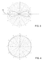
- Figs. 3 and 4 two sections, a vertical and a horizontal one, respectively, are shown, of the radiation diagram of a lighting device of the type represented in Fig. 1 .
- the overall output beam has a main emission direction 14 perpendicular to the focal axis 4.
- Such output beam has a divergence angle of about 60°.
- the lighting device 1, being it symmetrical with respect to the focal axis 4 has a uniform radiation diagram at 360° on a horizontal plane.
- the lighting device 1 may be associated to external collimation and/or reflection and/or protective shield devices.
- the lighting device 1 is part of a maritime signalling marker light or lighthouse's lighting device, it is possible to provide for a Fresnel lens that is adapted to intercept and collimate the deflected optical beams f3.
- means that are suitable, for example, to move the lighting device 1, for example, to rotate it around a generally vertical axis.
- the second reflector 6 is a frusto-conical reflector, and in which a support rod 15 is provided, which, by projecting from the minor base of the second reflector 6, acts as a support for the first reflector 3.
- the second reflector 6 is spaced apart from the array of sources 2.
Landscapes
- Engineering & Computer Science (AREA)
- General Engineering & Computer Science (AREA)
- Physics & Mathematics (AREA)
- Ocean & Marine Engineering (AREA)
- Radar, Positioning & Navigation (AREA)
- Microelectronics & Electronic Packaging (AREA)
- Optics & Photonics (AREA)
- General Physics & Mathematics (AREA)
- Combustion & Propulsion (AREA)
- Mechanical Engineering (AREA)
- Chemical & Material Sciences (AREA)
- Remote Sensing (AREA)
- Non-Portable Lighting Devices Or Systems Thereof (AREA)
Abstract
- an array of spatially distributed optoelectronic sources (2), each source (2) being adapted to emit a respective incident optical beam (f1);
- a first reflector (3) having an optical axis (4), and having a first reflective surface (5) that is concave and facing the array of sources (2) to intercept said incident optical beams (f1) and to produce corresponding reflected optical beams (f2);
- a second reflector (6) having a second reflective surface (7) interposed along said optical axis (4) between said array of optoelectronic sources (2) and the first reflector (3) adapted to intercept and deflect said reflected optical beams (f2) producing corresponding deflected optical beams (f3), the first reflector being such as to concentrate the reflected optical beams (f2) on the second reflective surface (7).
Description
- The present invention relates to the technical field of lighting devices, and in particular, it relates to a lighting device comprising an array of optoelectronic sources.
- In the technical field of the lighting devices, optoelectronic sources, such as, for example, LED sources to a greater extent, and laser sources to a lesser extent, are more and more widely used in replacement of the traditional incandescence sources. This involves advantages in terms of energy consumption and maintenance costs. In fact, the optoelectronic sources have lower power consumptions than those of incandescence lamps, and they have a service life that is longer than the incandescence lamps.
- Generally, due to emitted optical power needs, in order to replace an incandescence source, it is necessary to provide for an array of optoelectronic sources. Since such optoelectronic sources are sources spatially distributed in the array, in some cases it is not easy or feasible to use optoelectronic sources. Therefore, in such cases, it is necessary to provide for the adoption of traditional optical incandescence sources. This occurs, for example, but not exclusively, in the lighting devices with prevailing lateral emission that are employed as marker lights, lighthouses' lamps and lamps for maritime signalling. In such lighting devices, an incandescence lamp that is punctiform, or substantially punctiform, or generally spatially concentrated, is generally provided. Such incandescence lamp has an omnidirectional radiation diagram; due to this reason, a collimating lens is generally provided for, such as, for example, a Fresnel lens, suitable to modify the radiation diagram so that the marker light has, on the whole, desired directionality characteristics.
- A general object of the present description is to provide a lighting device with an array of spatially distributed optoelectronic sources that can be used alternatively to spatially concentrated incandescence sources.
- This and other objects are achieved by a lighting device as defined in
claim 1 in its most general embodiment, and in the claims dependent thereto, in some particular implementation forms thereof. - The invention will be better understood from the following detailed description of embodiments thereof, given by way of illustrative example, and by no way of limitation, relative to the accompanying drawings, in which:
-
Figure 1 shows a side sectional view of a first embodiment of a lighting device; -
Figure 2 shows a plane view of a part of the lighting device ofFigure 1 ; -
Figure 3 shows a first section of a radiation diagram of a lighting device of the type represented inFigure 1 ; -
Figure 4 shows a second embodiment of a radiation diagram of a lighting device of the type represented inFigure 1 ; and -
Figure 5 shows a side sectional view of a possible alternative embodiment of the lighting device ofFigure 1 . - In the appended Figures, similar or like elements will be designated by the same numeral references.
- In
Figure 1 , a lighting device is shown, comprising an array of spatially distributedoptoelectronic sources 2. In accordance with a non-limiting embodiment, thelighting device 1 is part of a maritime signaling marker light, or lighthouse's lamp or lamps for maritime signalling. In accordance with an alternative embodiment, the above-mentioned device is a lighting device for internal environments, for example, domestic environments. In accordance with possible further embodiments, the above-mentioned device is an external lighting device of a vehicle, such as a camping lamp or a lighting device for public or private external spaces. - In accordance with an embodiment, the
optoelectronic sources 2 are LED sources, i.e., each of them includes a LED diode. In accordance with a possible alternative embodiment, such sources are LASER sources, i.e., each of them includes a laser diode. - In accordance with an embodiment, the
optoelectronic sources 2 are secured to a support andsupply circuit board 20, for example, a printed board. The above-mentionedsources 2 are, for example, surface mount devices (SMDs) that are mounted on thecircuit board 20. In the above-mentioned embodiment, thesources 2 lay on a same plane; however, it shall be apparent that alternative embodiments may be provided, in which thedifferent sources 2 are arranged at mutually different heights. A thermal dissipation device may be associated to thecircuit board 20, for example, a finned plate, not shown in the Figures. Based on the powers that are used, alternative cooling systems may be provided, for example, a forced fluid circulation cooling system. - Each of the
optoelectronic sources 2 is suitable to emit a respective incident optical beam f1. In an ideal situation, such beam f1 is a perfectly collimated beam. As it is known, in a real situation such as the one illustrated inFigure 1 , above all in the case that theoptoelectronic sources 2 are LED sources, such beam f1 is a diverging beam. For example, in the case of LED sources, such beam f1 diverges according to an opening angle that may reach 120°, and that may be of only 10°; for example, it may range between 5°-8°, if theLED sources 2 are provided with a collimating lens facing the active surface of thesources 2. - The
lighting device 1 comprises afirst reflector 3 having anoptical axis 4 and having a first concavereflective surface 5 facing the array ofoptoelectronic sources 2. The concavereflective surface 5 is suitable to intercept the various incident optical beams f1 produced by theoptoelectronic sources 2 and to produce corresponding reflected optical beams f2. In accordance with a preferred embodiment, thefirst reflector 3 is a spherical reflector, i.e., it has areflective surface 5 that is a spherical cap. In accordance with possible alternative embodiments, thefirst reflector 3 is a parabolic or hyperbolic or elliptical reflector. - In the particular example represented in
Fig. 1 , thefirst reflector 3 is secured to thecircuit board 20 by means of a set ofsupport rods 11, for example, threerods 11, two of which are visible inFig. 1 . - The
lighting device 1 further comprises asecond reflector 6 having a secondreflective surface 7 interposed along theoptical axis 4 between the array ofoptoelectronic sources 2 and thefirst reflector 3. The reflective surface of thesecond reflector 6 is suitable to intercept and deflect the reflected optical beams f2 from thefirst reflector 3, producing corresponding deflected optical beams f3. Thefirst reflector 3 is such as to concentrate the reflected optical beams f2 onto thereflective surface 7 of thesecond reflector 6. In accordance with a preferred embodiment, thefirst reflector 3 allows mainly focusing most of the reflected optical beams f2 onto a spatially concentrated portion of thereflective surface 7. It shall be noticed that in this manner it is advantageously possible to sum, at such spatially concentrated portion, the optical beams emitted by the several sources. Therefore, by virtue of the combination of the two reflectors, it is possible to convert the sources of the array into a punctiform or almost punctiform or substantially spatially concentrated source. - In accordance with an embodiment, the
reflective surface 7 is a conical or frusto-conical surface. In the example represented inFig. 1 , thereflective surface 7 is a conical surface, i.e., a surface, or a surface portion, of a cone, having avertex 9 facing thefirst reflector 3. In accordance with an embodiment, it is possible to shape and mutually arrange thefirst reflector 3 and theconical surface 7 so that the reflected optical beams f2 are directed onto a spatially concentrated region of the conical surface, for example, around thevertex 9 of the cone, or a circular crown proximate to such vertex. For example, in accordance with a preferred embodiment in which thereflector 3 has a focus, it is possible to provide that thevertex 9 of the cone is arranged at, or at least in the proximity of, such focus. The same applies in the case that thesurface 7 is frusto-conical, since, in this case, a portion of such surface proximal at the minor base of the frustum of cone will be able to be arranged in the proximity of the above-mentioned focus. - In alternative embodiments, it is possible to provide that the
reflective surface 7 is different from a conical or frusto-conical surface, since thesecond reflector 6 may have other shapes, for example, dome-shaped or ogive-shaped, or for example, it may have an ellipsoid or a paraboloid shape. - As regards the first 3 and the second 6 reflectors, these can be made either in glass, or in plastic material, or in metal material coated with reflective and/or antioxidant paints.
- In
Fig. 2 , a possible embodiment ofcircuit board 20 is shown, on which theoptoelectronic sources 2 are mounted. In accordance with an embodiment, such as the one shown inFig. 2 , the array ofoptoelectronic sources 2 surrounds thesecond reflector 6. In the example, the array ofoptoelectronic sources 2 is distributed on a circular crown. In the particular example represented, the array ofsources 2 comprises an array of forty-five LEDs evenly spatially distributed on a circular crown having an outer diameter of 220 mm. By using 100 Lumen LEDs, a total light flow of 4500 Lumens is obtained. - It shall be noticed that in the embodiment described above, in which the
first reflector 3 is spherical, thesecond reflector 6 is conical or frusto-conical, and the array ofsources 2 is distributed on a circular crown, thelighting device 1 has a symmetry with respect to thefocal axis 4. However, it is possible to provide for asymmetric embodiments such as, for example, with reference toFig. 1 , an embodiment in which theoptical device 1 is only composed of one of the portions on the right side or the left side of theoptical axis 4. - In accordance with an embodiment, the second
reflective surface 7 is such as to produce deflected optical beams f3 that on the whole form an overall output beam having amain emission axis 14 transversal to thefocal axis 4 of thefirst reflector 3. For example, suchmain emission axis 14 is perpendicular to thefocal axis 4. In this case, thelighting device 1 may be defined as a device with lateral emission. - In
Figs. 3 and 4 , two sections, a vertical and a horizontal one, respectively, are shown, of the radiation diagram of a lighting device of the type represented inFig. 1 . InFig. 3 , it is possible to note that the overall output beam has amain emission direction 14 perpendicular to thefocal axis 4. Such output beam has a divergence angle of about 60°. InFig. 4 , instead, it is possible to note that thelighting device 1, being it symmetrical with respect to thefocal axis 4, has a uniform radiation diagram at 360° on a horizontal plane. - The
lighting device 1 may be associated to external collimation and/or reflection and/or protective shield devices. For example, in the case that thelighting device 1 is part of a maritime signalling marker light or lighthouse's lighting device, it is possible to provide for a Fresnel lens that is adapted to intercept and collimate the deflected optical beams f3. Furthermore, it is possible to provide for means that are suitable, for example, to move thelighting device 1, for example, to rotate it around a generally vertical axis. - Based on what has been described above, thus, it is possible to understand how a lighting device of the type described above allows achieving the above-mentioned objects with reference to the prior art. For example, numerical simulations have been carried out, which allowed to prove that a device of the type described above may be employed to replace an incandescence lamp in a lighthouse's
lighting device 5, with a large saving of energy consumption and maintenance costs. In such application, which is obviously an exemplary, non-limiting one, there is the further advantage that, unlike an incandescence lamp, through a lighting device of the type described above, it is possible to laterally direct the emitted light, thus avoiding to disperse the light upwardly, thereby improving the efficiency of the lighthouse. - Notwithstanding the principle of the invention, the embodiments and the implementation details will be widely varied with respect to what has been described and illustrated by way of non-limiting example only, without for this departing from the scope of the invention as defined in the appended claims.
- For example with reference to
Fig. 4 , it is possible to provide, inter alia, an embodiment of thelighting device 1 in which thesecond reflector 6 is a frusto-conical reflector, and in which a support rod 15 is provided, which, by projecting from the minor base of thesecond reflector 6, acts as a support for thefirst reflector 3. - In a further possible embodiment, it is possible to provide that the
second reflector 6 is spaced apart from the array ofsources 2.
Claims (15)
- A lighting device (1) comprising:- an array of spatially distributed optoelectronic sources (2), each source (2) being adapted to emit a respective incident optical beam (f1);- a first reflector (3) having an optical axis (4) and having a first concave reflective surface (5) and facing the array of sources (2) to intercept said incident optical beams (f1) and produce corresponding reflected optical beams (f2);- a second reflector (6) having a second reflective surface (7) interposed along said optical axis (4) between the array of optoelectronic sources (2) and the first reflector (3), and adapted to intercept and deflect the reflected optical beams (f2) producing corresponding deflected optical beams (f3), the first reflector (3) being such as to concentrate the reflected optical beams (f2) onto the second reflective surface (7).
- The lighting device (1) according to claim 1, wherein the first reflector (3) mainly allows focusing most of the reflected optical beams (f2) onto a spatially concentrated portion of the second reflective surface (7).
- The lighting device (1) according to claims 1 or 2, wherein the second reflective surface (7) is a conical or frusto-conical surface.
- The lighting device (1) according to claim 3, wherein the reflective surface (7) is a surface, or a surface portion, of a cone, having a vertex (9) facing the first reflector (3), or of a frustum of a cone, having the minor base facing the first reflector (3).
- The lighting device according to the claims 2 and 4, wherein said spatially concentrated portion is arranged in the proximity of said vertex (9) or said minor base.
- The lighting device according to claims 4 or 5, wherein the first reflector (3) has a focus, and wherein said vertex (9) or said minor base are arranged at or in the proximity of said focus.
- The lighting device (1) according to any one of the preceding claims, wherein the array of optoelectronic sources (2) surrounds the second reflector (6).
- The lighting device (1) according to claim 7, wherein the array of optoelectronic sources (2) is distributed on a circular crown.
- The lighting device (1) according to any one of the preceding claims, wherein the second reflective surface (7) is such as to produce deflected optical beams, which, on the whole, form an output beam having a main emission axis (14) that is transversal to said optical axis (4).
- The lighting device (1) according to claim 9, wherein the main emission axis (14) is perpendicular to said optical axis (4).
- The lighting device (1) according to any one of the preceding claims, wherein the optoelectronic sources (2) are LED sources.
- The lighting device (1) according to any one of the preceding claims, wherein the first reflector (3) is a spherical mirror.
- A lighthouse's lighting device comprising a lighting device (1) according to any one of the preceding claims.
- The lighthouse's lighting device according to claim 13, further comprising a Fresnel lens, which is adapted to intercept and collimate said deflected optical beams (f3).
- A maritime signalling lamp comprising a lighting device (1) according to any one of claims 1 to 12.
Applications Claiming Priority (1)
| Application Number | Priority Date | Filing Date | Title |
|---|---|---|---|
| IT000265A ITRM20120265A1 (en) | 2012-06-07 | 2012-06-07 | LIGHTING DEVICE INCLUDING AN OPTOELECTRONIC SOURCES BACK |
Publications (2)
| Publication Number | Publication Date |
|---|---|
| EP2671755A1 true EP2671755A1 (en) | 2013-12-11 |
| EP2671755B1 EP2671755B1 (en) | 2017-08-23 |
Family
ID=46727419
Family Applications (1)
| Application Number | Title | Priority Date | Filing Date |
|---|---|---|---|
| EP13167053.1A Not-in-force EP2671755B1 (en) | 2012-06-07 | 2013-05-08 | Lighting device comprising an array of optoelectronic sources |
Country Status (3)
| Country | Link |
|---|---|
| US (1) | US9007237B2 (en) |
| EP (1) | EP2671755B1 (en) |
| IT (1) | ITRM20120265A1 (en) |
Cited By (2)
| Publication number | Priority date | Publication date | Assignee | Title |
|---|---|---|---|---|
| WO2021191130A1 (en) * | 2020-03-23 | 2021-09-30 | Osram Gmbh | Reflector optics for a retrofit vehicle headlight lamp |
| US11761601B2 (en) | 2020-03-23 | 2023-09-19 | Osram Gmbh | Automotive solid-state retrofit headlamp |
Families Citing this family (10)
| Publication number | Priority date | Publication date | Assignee | Title |
|---|---|---|---|---|
| ITRM20120265A1 (en) * | 2012-06-07 | 2013-12-08 | Consiglio Nazionale Ricerche | LIGHTING DEVICE INCLUDING AN OPTOELECTRONIC SOURCES BACK |
| DE102014101685A1 (en) * | 2014-02-11 | 2015-08-13 | Huf Hülsbeck & Fürst Gmbh & Co. Kg | camera device |
| US9279562B2 (en) * | 2014-03-18 | 2016-03-08 | Goodrich Corporation | Systems and methods for anti-collision lights |
| US9784432B2 (en) * | 2014-05-21 | 2017-10-10 | Abl Ip Holding Llc | Optical assembly with form-analogous optics for translucent luminaire |
| JP6461569B2 (en) * | 2014-11-25 | 2019-01-30 | スタンレー電気株式会社 | Lighting device |
| CN104950518A (en) * | 2015-07-21 | 2015-09-30 | 京东方科技集团股份有限公司 | Quantum dot film, preparation method thereof, and backlight module |
| WO2017212589A1 (en) * | 2016-06-08 | 2017-12-14 | 堺ディスプレイプロダクト株式会社 | Light reflection device and light source device |
| TWI625589B (en) * | 2017-03-27 | 2018-06-01 | 晶睿通訊股份有限公司 | Lamp cup and camera |
| DE102019100904A1 (en) * | 2019-01-15 | 2020-07-16 | HELLA GmbH & Co. KGaA | Lighting device and light module |
| DE102020203735A1 (en) * | 2020-03-23 | 2021-09-23 | Osram Gmbh | Vehicle retrofit headlight lamp with reflector areas facing each other |
Citations (3)
| Publication number | Priority date | Publication date | Assignee | Title |
|---|---|---|---|---|
| US20040257546A1 (en) * | 2003-04-17 | 2004-12-23 | Asml Netherlands B.V. | Lithographic projection apparatus with collector including concave and convex mirrors |
| WO2005078338A1 (en) * | 2004-02-17 | 2005-08-25 | Kelly William M | A utility lamp |
| US20090296416A1 (en) * | 2008-05-28 | 2009-12-03 | Osram Sylvania, Inc. | Rear-loaded light emitting diode module for automotive rear combination lamps |
Family Cites Families (40)
| Publication number | Priority date | Publication date | Assignee | Title |
|---|---|---|---|---|
| US5659409A (en) * | 1992-10-09 | 1997-08-19 | Ag Technology Co., Ltd. | Light source apparatus using a cone-like material and an applied apparatus thereof |
| US5782553A (en) * | 1993-10-28 | 1998-07-21 | Mcdermott; Kevin | Multiple lamp lighting device |
| US5988836A (en) * | 1996-07-31 | 1999-11-23 | Swarens; Ralph W. | Recessed indirect fluorescent light fixture with flexible reflector |
| JPH10268449A (en) * | 1997-03-24 | 1998-10-09 | Fuji Photo Optical Co Ltd | Illuminating optical system and projection optical system using the same |
| US6361190B1 (en) * | 1999-06-25 | 2002-03-26 | Mcdermott Kevin | Large surface LED lighting device |
| US6729746B2 (en) * | 2000-03-14 | 2004-05-04 | Toyoda Gosei Co., Ltd. | Light source device |
| US6573659B2 (en) * | 2000-03-31 | 2003-06-03 | Carmanah Technologies, Inc. | Solar-powered light assembly with automatic light control |
| JP3753011B2 (en) * | 2001-04-11 | 2006-03-08 | 豊田合成株式会社 | Reflective light emitting diode |
| EP2420873A3 (en) * | 2001-12-14 | 2013-01-16 | QUALCOMM MEMS Technologies, Inc. | Uniform illumination system |
| US7160002B2 (en) * | 2002-06-20 | 2007-01-09 | Simon Jerome H | Segmented reflector systems and combined reflector and refractor systems |
| US6851835B2 (en) * | 2002-12-17 | 2005-02-08 | Whelen Engineering Company, Inc. | Large area shallow-depth full-fill LED light assembly |
| US6758582B1 (en) * | 2003-03-19 | 2004-07-06 | Elumina Technology Incorporation | LED lighting device |
| US7246917B2 (en) * | 2003-08-12 | 2007-07-24 | Illumination Management Solutions, Inc. | Apparatus and method for using emitting diodes (LED) in a side-emitting device |
| JP4437707B2 (en) * | 2004-06-24 | 2010-03-24 | 株式会社小糸製作所 | License plate lighting system |
| JP4089692B2 (en) * | 2004-09-02 | 2008-05-28 | 株式会社パトライト | Lens parts, signal indicator display unit and signal indicator |
| US20060077667A1 (en) * | 2004-10-07 | 2006-04-13 | Choon Nang Electrical Appliance Mfy., Ltd. | Lighting device |
| US8541795B2 (en) * | 2004-10-12 | 2013-09-24 | Cree, Inc. | Side-emitting optical coupling device |
| JP4449768B2 (en) * | 2005-02-02 | 2010-04-14 | 株式会社ニコン | Polarization conversion element and projection apparatus including the same |
| CN101326553B (en) * | 2005-05-09 | 2011-11-30 | Bwt产权公司 | Optical signaling apparatus with precise beam control |
| US7357530B2 (en) * | 2005-07-15 | 2008-04-15 | Bwt Property, Inc. | Lighting apparatus for navigational aids |
| DE102006044019B4 (en) * | 2006-09-15 | 2011-12-29 | Stiftung Alfred-Wegener-Institut für Polar- und Meeresforschung Stiftung des öffentlichen Rechts | reflector spotlight |
| DE102007061304B4 (en) * | 2006-12-19 | 2010-09-02 | Koito Manufacturing Co., Ltd. | vehicle light |
| US7330314B1 (en) * | 2007-02-28 | 2008-02-12 | Corning Incorporated | Color combiner for solid-state light sources |
| US7794124B2 (en) * | 2007-09-25 | 2010-09-14 | Michael Hulsey | Bi-directional boat running and emergency light apparatus and method |
| WO2009062053A1 (en) * | 2007-11-08 | 2009-05-14 | Dialight Corporation | Double collimator led color mixing system |
| US8287147B2 (en) * | 2008-11-15 | 2012-10-16 | Rongsheng Tian | LED based omni-directional light engine |
| JP5212720B2 (en) * | 2008-12-11 | 2013-06-19 | スタンレー電気株式会社 | Lamp |
| DE202009011500U1 (en) * | 2009-08-20 | 2010-12-30 | Arnold & Richter Cine Technik Gmbh & Co. Betriebs Kg | Optical system for an LED light |
| US9703204B2 (en) * | 2010-04-02 | 2017-07-11 | Nikon Corporation | Light source apparatus, optical apparatus, exposure apparatus, device manufacturing method, illuminating method, exposure method, and method for manufacturing optical apparatus |
| RU2594487C2 (en) * | 2010-04-28 | 2016-08-20 | Конинклейке Филипс Электроникс Н.В. | Defocused optics for multichip light-emitting diode |
| US8827491B2 (en) * | 2010-07-14 | 2014-09-09 | Enplas Corporation | Lighting device |
| JP4995989B2 (en) * | 2010-10-12 | 2012-08-08 | パナソニック株式会社 | lamp |
| IT1402670B1 (en) * | 2010-11-05 | 2013-09-13 | Sirio Panel Spa | LED LIGHTING DEVICE FOR AN AIRCRAFT, IN PARTICULAR FOR LANDING, TAKE-OFF, ROLLER, AND SEARCH OPERATIONS, AND AIRCRAFT INCLUDING THE LED LIGHTING DEVICE |
| CN103443664B (en) * | 2011-03-25 | 2015-08-05 | 纳卢克斯株式会社 | Lighting device |
| JP6250541B2 (en) * | 2011-08-19 | 2017-12-20 | フィリップス ライティング ホールディング ビー ヴィ | Candle light LED bulb |
| KR20130032110A (en) * | 2011-09-22 | 2013-04-01 | 삼성전자주식회사 | Lighting device |
| US20130279164A1 (en) * | 2012-04-20 | 2013-10-24 | Epistar Corporation | Led lighting fixtures |
| CN103375768A (en) * | 2012-04-26 | 2013-10-30 | 全亿大科技(佛山)有限公司 | Lens and light source module |
| ITRM20120265A1 (en) * | 2012-06-07 | 2013-12-08 | Consiglio Nazionale Ricerche | LIGHTING DEVICE INCLUDING AN OPTOELECTRONIC SOURCES BACK |
| DE102013206488A1 (en) * | 2013-04-11 | 2014-10-30 | Automotive Lighting Reutlingen Gmbh | Light module for a motor vehicle lighting device |
-
2012
- 2012-06-07 IT IT000265A patent/ITRM20120265A1/en unknown
-
2013
- 2013-05-08 EP EP13167053.1A patent/EP2671755B1/en not_active Not-in-force
- 2013-05-31 US US13/906,426 patent/US9007237B2/en not_active Expired - Fee Related
Patent Citations (3)
| Publication number | Priority date | Publication date | Assignee | Title |
|---|---|---|---|---|
| US20040257546A1 (en) * | 2003-04-17 | 2004-12-23 | Asml Netherlands B.V. | Lithographic projection apparatus with collector including concave and convex mirrors |
| WO2005078338A1 (en) * | 2004-02-17 | 2005-08-25 | Kelly William M | A utility lamp |
| US20090296416A1 (en) * | 2008-05-28 | 2009-12-03 | Osram Sylvania, Inc. | Rear-loaded light emitting diode module for automotive rear combination lamps |
Cited By (3)
| Publication number | Priority date | Publication date | Assignee | Title |
|---|---|---|---|---|
| WO2021191130A1 (en) * | 2020-03-23 | 2021-09-30 | Osram Gmbh | Reflector optics for a retrofit vehicle headlight lamp |
| US11761601B2 (en) | 2020-03-23 | 2023-09-19 | Osram Gmbh | Automotive solid-state retrofit headlamp |
| US12007089B2 (en) | 2020-03-23 | 2024-06-11 | Osram Gmbh | Reflector optics for a vehicle retrofit headlamp |
Also Published As
| Publication number | Publication date |
|---|---|
| EP2671755B1 (en) | 2017-08-23 |
| US20140002281A1 (en) | 2014-01-02 |
| ITRM20120265A1 (en) | 2013-12-08 |
| US9007237B2 (en) | 2015-04-14 |
Similar Documents
| Publication | Publication Date | Title |
|---|---|---|
| EP2671755B1 (en) | Lighting device comprising an array of optoelectronic sources | |
| US8919994B2 (en) | Illumination system and lamp utilizing directionalized LEDs | |
| RU2137978C1 (en) | Lighting fixture with asymmetric distribution of light flux relative to optical axis | |
| US10295150B2 (en) | Asymmetrical optical system | |
| JP6096180B2 (en) | Light emitting diode light source | |
| US8596841B2 (en) | Vehicle lamp | |
| JP5257609B2 (en) | Optical module and lighting fixture | |
| KR20100017138A (en) | An improved led device for wide beam generation and method of making the same | |
| KR102432262B1 (en) | Vehicle lighting module | |
| CN105716023B (en) | A kind of car headlamp component and car headlamp | |
| EP3273144B1 (en) | Led spotlight | |
| US20120327645A1 (en) | Flood lamp with improved angular lighting uniformity | |
| JP6130982B1 (en) | Light emitting diode lamp | |
| JP2010161033A (en) | Illumination device | |
| JP2014182994A (en) | Lighting device | |
| EP2984389A1 (en) | Optical system for a directional lamp | |
| KR101529166B1 (en) | Lamp for vehicle | |
| KR101055519B1 (en) | Lighting assembly and equalizer with same | |
| US11480314B2 (en) | Light collimation assembly and light emitting devices | |
| CN105953175B (en) | Projecting lamp lens, have light-emitting module and projecting lamp of this projecting lamp lens | |
| JP5950198B2 (en) | lighting equipment | |
| CN213712678U (en) | LED module, LED module combination and lamp | |
| JP2016212371A (en) | Luminous flux control member, light-emitting device and luminaire | |
| KR102166854B1 (en) | Head lamp for vehicles | |
| KR20190016164A (en) | LED searchlight |
Legal Events
| Date | Code | Title | Description |
|---|---|---|---|
| PUAI | Public reference made under article 153(3) epc to a published international application that has entered the european phase |
Free format text: ORIGINAL CODE: 0009012 |
|
| AK | Designated contracting states |
Kind code of ref document: A1 Designated state(s): AL AT BE BG CH CY CZ DE DK EE ES FI FR GB GR HR HU IE IS IT LI LT LU LV MC MK MT NL NO PL PT RO RS SE SI SK SM TR |
|
| AX | Request for extension of the european patent |
Extension state: BA ME |
|
| 17P | Request for examination filed |
Effective date: 20140609 |
|
| RBV | Designated contracting states (corrected) |
Designated state(s): AL AT BE BG CH CY CZ DE DK EE ES FI FR GB GR HR HU IE IS IT LI LT LU LV MC MK MT NL NO PL PT RO RS SE SI SK SM TR |
|
| REG | Reference to a national code |
Ref country code: DE Ref legal event code: R079 Ref document number: 602013025342 Country of ref document: DE Free format text: PREVIOUS MAIN CLASS: B60Q0001000000 Ipc: B63B0051020000 |
|
| GRAP | Despatch of communication of intention to grant a patent |
Free format text: ORIGINAL CODE: EPIDOSNIGR1 |
|
| RIC1 | Information provided on ipc code assigned before grant |
Ipc: F21Y 105/12 20160101ALI20170223BHEP Ipc: F21Y 105/10 20160101ALI20170223BHEP Ipc: H05B 33/08 20060101ALI20170223BHEP Ipc: F21W 131/10 20060101ALI20170223BHEP Ipc: F21V 7/04 20060101ALI20170223BHEP Ipc: G08G 3/00 20060101ALI20170223BHEP Ipc: F21V 7/07 20060101ALI20170223BHEP Ipc: F21Y 115/30 20160101ALI20170223BHEP Ipc: F21V 7/22 20060101ALI20170223BHEP Ipc: F21S 8/10 20060101ALI20170223BHEP Ipc: F21V 7/08 20060101ALI20170223BHEP Ipc: F21K 9/00 20160101ALI20170223BHEP Ipc: F21W 111/043 20060101ALI20170223BHEP Ipc: B63B 51/02 20060101AFI20170223BHEP Ipc: F21Y 115/10 20160101ALI20170223BHEP Ipc: F21V 7/00 20060101ALI20170223BHEP Ipc: F21V 7/06 20060101ALI20170223BHEP |
|
| INTG | Intention to grant announced |
Effective date: 20170314 |
|
| RIN1 | Information on inventor provided before grant (corrected) |
Inventor name: SANSONI, PAOLA Inventor name: MERCATELLI, LUCA Inventor name: FRANCINI, FRANCO Inventor name: SANI, ELISA Inventor name: JAFRANCESCO, DAVID Inventor name: FONTANI, DANIELA |
|
| GRAS | Grant fee paid |
Free format text: ORIGINAL CODE: EPIDOSNIGR3 |
|
| GRAA | (expected) grant |
Free format text: ORIGINAL CODE: 0009210 |
|
| AK | Designated contracting states |
Kind code of ref document: B1 Designated state(s): AL AT BE BG CH CY CZ DE DK EE ES FI FR GB GR HR HU IE IS IT LI LT LU LV MC MK MT NL NO PL PT RO RS SE SI SK SM TR |
|
| REG | Reference to a national code |
Ref country code: GB Ref legal event code: FG4D |
|
| REG | Reference to a national code |
Ref country code: CH Ref legal event code: EP |
|
| REG | Reference to a national code |
Ref country code: AT Ref legal event code: REF Ref document number: 921021 Country of ref document: AT Kind code of ref document: T Effective date: 20170915 |
|
| REG | Reference to a national code |
Ref country code: IE Ref legal event code: FG4D |
|
| REG | Reference to a national code |
Ref country code: DE Ref legal event code: R096 Ref document number: 602013025342 Country of ref document: DE |
|
| REG | Reference to a national code |
Ref country code: NL Ref legal event code: MP Effective date: 20170823 |
|
| REG | Reference to a national code |
Ref country code: LT Ref legal event code: MG4D |
|
| REG | Reference to a national code |
Ref country code: AT Ref legal event code: MK05 Ref document number: 921021 Country of ref document: AT Kind code of ref document: T Effective date: 20170823 |
|
| PG25 | Lapsed in a contracting state [announced via postgrant information from national office to epo] |
Ref country code: LT Free format text: LAPSE BECAUSE OF FAILURE TO SUBMIT A TRANSLATION OF THE DESCRIPTION OR TO PAY THE FEE WITHIN THE PRESCRIBED TIME-LIMIT Effective date: 20170823 Ref country code: HR Free format text: LAPSE BECAUSE OF FAILURE TO SUBMIT A TRANSLATION OF THE DESCRIPTION OR TO PAY THE FEE WITHIN THE PRESCRIBED TIME-LIMIT Effective date: 20170823 Ref country code: SE Free format text: LAPSE BECAUSE OF FAILURE TO SUBMIT A TRANSLATION OF THE DESCRIPTION OR TO PAY THE FEE WITHIN THE PRESCRIBED TIME-LIMIT Effective date: 20170823 Ref country code: NL Free format text: LAPSE BECAUSE OF FAILURE TO SUBMIT A TRANSLATION OF THE DESCRIPTION OR TO PAY THE FEE WITHIN THE PRESCRIBED TIME-LIMIT Effective date: 20170823 Ref country code: FI Free format text: LAPSE BECAUSE OF FAILURE TO SUBMIT A TRANSLATION OF THE DESCRIPTION OR TO PAY THE FEE WITHIN THE PRESCRIBED TIME-LIMIT Effective date: 20170823 Ref country code: AT Free format text: LAPSE BECAUSE OF FAILURE TO SUBMIT A TRANSLATION OF THE DESCRIPTION OR TO PAY THE FEE WITHIN THE PRESCRIBED TIME-LIMIT Effective date: 20170823 Ref country code: NO Free format text: LAPSE BECAUSE OF FAILURE TO SUBMIT A TRANSLATION OF THE DESCRIPTION OR TO PAY THE FEE WITHIN THE PRESCRIBED TIME-LIMIT Effective date: 20171123 |
|
| PG25 | Lapsed in a contracting state [announced via postgrant information from national office to epo] |
Ref country code: PL Free format text: LAPSE BECAUSE OF FAILURE TO SUBMIT A TRANSLATION OF THE DESCRIPTION OR TO PAY THE FEE WITHIN THE PRESCRIBED TIME-LIMIT Effective date: 20170823 Ref country code: IS Free format text: LAPSE BECAUSE OF FAILURE TO SUBMIT A TRANSLATION OF THE DESCRIPTION OR TO PAY THE FEE WITHIN THE PRESCRIBED TIME-LIMIT Effective date: 20171223 Ref country code: ES Free format text: LAPSE BECAUSE OF FAILURE TO SUBMIT A TRANSLATION OF THE DESCRIPTION OR TO PAY THE FEE WITHIN THE PRESCRIBED TIME-LIMIT Effective date: 20170823 Ref country code: LV Free format text: LAPSE BECAUSE OF FAILURE TO SUBMIT A TRANSLATION OF THE DESCRIPTION OR TO PAY THE FEE WITHIN THE PRESCRIBED TIME-LIMIT Effective date: 20170823 Ref country code: RS Free format text: LAPSE BECAUSE OF FAILURE TO SUBMIT A TRANSLATION OF THE DESCRIPTION OR TO PAY THE FEE WITHIN THE PRESCRIBED TIME-LIMIT Effective date: 20170823 Ref country code: BG Free format text: LAPSE BECAUSE OF FAILURE TO SUBMIT A TRANSLATION OF THE DESCRIPTION OR TO PAY THE FEE WITHIN THE PRESCRIBED TIME-LIMIT Effective date: 20171123 Ref country code: GR Free format text: LAPSE BECAUSE OF FAILURE TO SUBMIT A TRANSLATION OF THE DESCRIPTION OR TO PAY THE FEE WITHIN THE PRESCRIBED TIME-LIMIT Effective date: 20171124 |
|
| PG25 | Lapsed in a contracting state [announced via postgrant information from national office to epo] |
Ref country code: CZ Free format text: LAPSE BECAUSE OF FAILURE TO SUBMIT A TRANSLATION OF THE DESCRIPTION OR TO PAY THE FEE WITHIN THE PRESCRIBED TIME-LIMIT Effective date: 20170823 Ref country code: DK Free format text: LAPSE BECAUSE OF FAILURE TO SUBMIT A TRANSLATION OF THE DESCRIPTION OR TO PAY THE FEE WITHIN THE PRESCRIBED TIME-LIMIT Effective date: 20170823 Ref country code: RO Free format text: LAPSE BECAUSE OF FAILURE TO SUBMIT A TRANSLATION OF THE DESCRIPTION OR TO PAY THE FEE WITHIN THE PRESCRIBED TIME-LIMIT Effective date: 20170823 |
|
| REG | Reference to a national code |
Ref country code: DE Ref legal event code: R097 Ref document number: 602013025342 Country of ref document: DE |
|
| PG25 | Lapsed in a contracting state [announced via postgrant information from national office to epo] |
Ref country code: EE Free format text: LAPSE BECAUSE OF FAILURE TO SUBMIT A TRANSLATION OF THE DESCRIPTION OR TO PAY THE FEE WITHIN THE PRESCRIBED TIME-LIMIT Effective date: 20170823 Ref country code: SM Free format text: LAPSE BECAUSE OF FAILURE TO SUBMIT A TRANSLATION OF THE DESCRIPTION OR TO PAY THE FEE WITHIN THE PRESCRIBED TIME-LIMIT Effective date: 20170823 Ref country code: SK Free format text: LAPSE BECAUSE OF FAILURE TO SUBMIT A TRANSLATION OF THE DESCRIPTION OR TO PAY THE FEE WITHIN THE PRESCRIBED TIME-LIMIT Effective date: 20170823 |
|
| PLBE | No opposition filed within time limit |
Free format text: ORIGINAL CODE: 0009261 |
|
| STAA | Information on the status of an ep patent application or granted ep patent |
Free format text: STATUS: NO OPPOSITION FILED WITHIN TIME LIMIT |
|
| REG | Reference to a national code |
Ref country code: FR Ref legal event code: PLFP Year of fee payment: 6 |
|
| 26N | No opposition filed |
Effective date: 20180524 |
|
| PG25 | Lapsed in a contracting state [announced via postgrant information from national office to epo] |
Ref country code: SI Free format text: LAPSE BECAUSE OF FAILURE TO SUBMIT A TRANSLATION OF THE DESCRIPTION OR TO PAY THE FEE WITHIN THE PRESCRIBED TIME-LIMIT Effective date: 20170823 |
|
| REG | Reference to a national code |
Ref country code: CH Ref legal event code: PL |
|
| REG | Reference to a national code |
Ref country code: BE Ref legal event code: MM Effective date: 20180531 |
|
| PG25 | Lapsed in a contracting state [announced via postgrant information from national office to epo] |
Ref country code: MC Free format text: LAPSE BECAUSE OF FAILURE TO SUBMIT A TRANSLATION OF THE DESCRIPTION OR TO PAY THE FEE WITHIN THE PRESCRIBED TIME-LIMIT Effective date: 20170823 |
|
| REG | Reference to a national code |
Ref country code: IE Ref legal event code: MM4A |
|
| PG25 | Lapsed in a contracting state [announced via postgrant information from national office to epo] |
Ref country code: CH Free format text: LAPSE BECAUSE OF NON-PAYMENT OF DUE FEES Effective date: 20180531 Ref country code: LI Free format text: LAPSE BECAUSE OF NON-PAYMENT OF DUE FEES Effective date: 20180531 |
|
| PG25 | Lapsed in a contracting state [announced via postgrant information from national office to epo] |
Ref country code: LU Free format text: LAPSE BECAUSE OF NON-PAYMENT OF DUE FEES Effective date: 20180508 |
|
| PG25 | Lapsed in a contracting state [announced via postgrant information from national office to epo] |
Ref country code: IE Free format text: LAPSE BECAUSE OF NON-PAYMENT OF DUE FEES Effective date: 20180508 |
|
| PG25 | Lapsed in a contracting state [announced via postgrant information from national office to epo] |
Ref country code: BE Free format text: LAPSE BECAUSE OF NON-PAYMENT OF DUE FEES Effective date: 20180531 |
|
| PG25 | Lapsed in a contracting state [announced via postgrant information from national office to epo] |
Ref country code: MT Free format text: LAPSE BECAUSE OF NON-PAYMENT OF DUE FEES Effective date: 20180508 |
|
| PG25 | Lapsed in a contracting state [announced via postgrant information from national office to epo] |
Ref country code: TR Free format text: LAPSE BECAUSE OF FAILURE TO SUBMIT A TRANSLATION OF THE DESCRIPTION OR TO PAY THE FEE WITHIN THE PRESCRIBED TIME-LIMIT Effective date: 20170823 |
|
| PG25 | Lapsed in a contracting state [announced via postgrant information from national office to epo] |
Ref country code: HU Free format text: LAPSE BECAUSE OF FAILURE TO SUBMIT A TRANSLATION OF THE DESCRIPTION OR TO PAY THE FEE WITHIN THE PRESCRIBED TIME-LIMIT; INVALID AB INITIO Effective date: 20130508 Ref country code: PT Free format text: LAPSE BECAUSE OF FAILURE TO SUBMIT A TRANSLATION OF THE DESCRIPTION OR TO PAY THE FEE WITHIN THE PRESCRIBED TIME-LIMIT Effective date: 20170823 |
|
| PG25 | Lapsed in a contracting state [announced via postgrant information from national office to epo] |
Ref country code: CY Free format text: LAPSE BECAUSE OF FAILURE TO SUBMIT A TRANSLATION OF THE DESCRIPTION OR TO PAY THE FEE WITHIN THE PRESCRIBED TIME-LIMIT Effective date: 20170823 Ref country code: MK Free format text: LAPSE BECAUSE OF NON-PAYMENT OF DUE FEES Effective date: 20170823 |
|
| PG25 | Lapsed in a contracting state [announced via postgrant information from national office to epo] |
Ref country code: AL Free format text: LAPSE BECAUSE OF FAILURE TO SUBMIT A TRANSLATION OF THE DESCRIPTION OR TO PAY THE FEE WITHIN THE PRESCRIBED TIME-LIMIT Effective date: 20170823 |
|
| PGFP | Annual fee paid to national office [announced via postgrant information from national office to epo] |
Ref country code: IT Payment date: 20210505 Year of fee payment: 9 Ref country code: FR Payment date: 20210531 Year of fee payment: 9 Ref country code: DE Payment date: 20210520 Year of fee payment: 9 |
|
| PGFP | Annual fee paid to national office [announced via postgrant information from national office to epo] |
Ref country code: GB Payment date: 20210525 Year of fee payment: 9 |
|
| REG | Reference to a national code |
Ref country code: DE Ref legal event code: R119 Ref document number: 602013025342 Country of ref document: DE |
|
| GBPC | Gb: european patent ceased through non-payment of renewal fee |
Effective date: 20220508 |
|
| PG25 | Lapsed in a contracting state [announced via postgrant information from national office to epo] |
Ref country code: FR Free format text: LAPSE BECAUSE OF NON-PAYMENT OF DUE FEES Effective date: 20220531 |
|
| PG25 | Lapsed in a contracting state [announced via postgrant information from national office to epo] |
Ref country code: GB Free format text: LAPSE BECAUSE OF NON-PAYMENT OF DUE FEES Effective date: 20220508 Ref country code: DE Free format text: LAPSE BECAUSE OF NON-PAYMENT OF DUE FEES Effective date: 20221201 |
|
| PG25 | Lapsed in a contracting state [announced via postgrant information from national office to epo] |
Ref country code: IT Free format text: LAPSE BECAUSE OF NON-PAYMENT OF DUE FEES Effective date: 20220508 |