EP2671704B1 - System for spacing and transferring objects between operative stations - Google Patents
System for spacing and transferring objects between operative stations Download PDFInfo
- Publication number
- EP2671704B1 EP2671704B1 EP13170667.3A EP13170667A EP2671704B1 EP 2671704 B1 EP2671704 B1 EP 2671704B1 EP 13170667 A EP13170667 A EP 13170667A EP 2671704 B1 EP2671704 B1 EP 2671704B1
- Authority
- EP
- European Patent Office
- Prior art keywords
- driving wheel
- pitch
- plier
- objects
- pair
- Prior art date
- Legal status (The legal status is an assumption and is not a legal conclusion. Google has not performed a legal analysis and makes no representation as to the accuracy of the status listed.)
- Active
Links
Images




Classifications
-
- B—PERFORMING OPERATIONS; TRANSPORTING
- B65—CONVEYING; PACKING; STORING; HANDLING THIN OR FILAMENTARY MATERIAL
- B65G—TRANSPORT OR STORAGE DEVICES, e.g. CONVEYORS FOR LOADING OR TIPPING, SHOP CONVEYOR SYSTEMS OR PNEUMATIC TUBE CONVEYORS
- B65G47/00—Article or material-handling devices associated with conveyors; Methods employing such devices
- B65G47/22—Devices influencing the relative position or the attitude of articles during transit by conveyors
- B65G47/26—Devices influencing the relative position or the attitude of articles during transit by conveyors arranging the articles, e.g. varying spacing between individual articles
- B65G47/30—Devices influencing the relative position or the attitude of articles during transit by conveyors arranging the articles, e.g. varying spacing between individual articles during transit by a series of conveyors
-
- B—PERFORMING OPERATIONS; TRANSPORTING
- B29—WORKING OF PLASTICS; WORKING OF SUBSTANCES IN A PLASTIC STATE IN GENERAL
- B29C—SHAPING OR JOINING OF PLASTICS; SHAPING OF MATERIAL IN A PLASTIC STATE, NOT OTHERWISE PROVIDED FOR; AFTER-TREATMENT OF THE SHAPED PRODUCTS, e.g. REPAIRING
- B29C49/00—Blow-moulding, i.e. blowing a preform or parison to a desired shape within a mould; Apparatus therefor
- B29C49/42—Component parts, details or accessories; Auxiliary operations
- B29C49/4205—Handling means, e.g. transfer, loading or discharging means
- B29C49/42113—Means for manipulating the objects' position or orientation
- B29C49/42121—Changing the center-center distance
- B29C49/42122—Adapting to blow-mould cavity center-center distance
-
- B—PERFORMING OPERATIONS; TRANSPORTING
- B29—WORKING OF PLASTICS; WORKING OF SUBSTANCES IN A PLASTIC STATE IN GENERAL
- B29C—SHAPING OR JOINING OF PLASTICS; SHAPING OF MATERIAL IN A PLASTIC STATE, NOT OTHERWISE PROVIDED FOR; AFTER-TREATMENT OF THE SHAPED PRODUCTS, e.g. REPAIRING
- B29C49/00—Blow-moulding, i.e. blowing a preform or parison to a desired shape within a mould; Apparatus therefor
- B29C49/42—Component parts, details or accessories; Auxiliary operations
- B29C49/4205—Handling means, e.g. transfer, loading or discharging means
- B29C49/42073—Grippers
-
- B—PERFORMING OPERATIONS; TRANSPORTING
- B29—WORKING OF PLASTICS; WORKING OF SUBSTANCES IN A PLASTIC STATE IN GENERAL
- B29C—SHAPING OR JOINING OF PLASTICS; SHAPING OF MATERIAL IN A PLASTIC STATE, NOT OTHERWISE PROVIDED FOR; AFTER-TREATMENT OF THE SHAPED PRODUCTS, e.g. REPAIRING
- B29C49/00—Blow-moulding, i.e. blowing a preform or parison to a desired shape within a mould; Apparatus therefor
- B29C49/42—Component parts, details or accessories; Auxiliary operations
- B29C49/4205—Handling means, e.g. transfer, loading or discharging means
- B29C49/42093—Transporting apparatus, e.g. slides, wheels or conveyors
- B29C49/42095—Rotating wheels or stars
-
- B—PERFORMING OPERATIONS; TRANSPORTING
- B29—WORKING OF PLASTICS; WORKING OF SUBSTANCES IN A PLASTIC STATE IN GENERAL
- B29C—SHAPING OR JOINING OF PLASTICS; SHAPING OF MATERIAL IN A PLASTIC STATE, NOT OTHERWISE PROVIDED FOR; AFTER-TREATMENT OF THE SHAPED PRODUCTS, e.g. REPAIRING
- B29C49/00—Blow-moulding, i.e. blowing a preform or parison to a desired shape within a mould; Apparatus therefor
- B29C49/42—Component parts, details or accessories; Auxiliary operations
- B29C49/4205—Handling means, e.g. transfer, loading or discharging means
- B29C49/42093—Transporting apparatus, e.g. slides, wheels or conveyors
- B29C49/42097—Sliding rails, e.g. inclined
-
- F—MECHANICAL ENGINEERING; LIGHTING; HEATING; WEAPONS; BLASTING
- F27—FURNACES; KILNS; OVENS; RETORTS
- F27D—DETAILS OR ACCESSORIES OF FURNACES, KILNS, OVENS OR RETORTS, IN SO FAR AS THEY ARE OF KINDS OCCURRING IN MORE THAN ONE KIND OF FURNACE
- F27D3/00—Charging; Discharging; Manipulation of charge
-
- B—PERFORMING OPERATIONS; TRANSPORTING
- B29—WORKING OF PLASTICS; WORKING OF SUBSTANCES IN A PLASTIC STATE IN GENERAL
- B29C—SHAPING OR JOINING OF PLASTICS; SHAPING OF MATERIAL IN A PLASTIC STATE, NOT OTHERWISE PROVIDED FOR; AFTER-TREATMENT OF THE SHAPED PRODUCTS, e.g. REPAIRING
- B29C2949/00—Indexing scheme relating to blow-moulding
- B29C2949/07—Preforms or parisons characterised by their configuration
- B29C2949/0715—Preforms or parisons characterised by their configuration the preform having one end closed
-
- B—PERFORMING OPERATIONS; TRANSPORTING
- B29—WORKING OF PLASTICS; WORKING OF SUBSTANCES IN A PLASTIC STATE IN GENERAL
- B29C—SHAPING OR JOINING OF PLASTICS; SHAPING OF MATERIAL IN A PLASTIC STATE, NOT OTHERWISE PROVIDED FOR; AFTER-TREATMENT OF THE SHAPED PRODUCTS, e.g. REPAIRING
- B29C49/00—Blow-moulding, i.e. blowing a preform or parison to a desired shape within a mould; Apparatus therefor
- B29C49/02—Combined blow-moulding and manufacture of the preform or the parison
- B29C49/06—Injection blow-moulding
-
- B—PERFORMING OPERATIONS; TRANSPORTING
- B29—WORKING OF PLASTICS; WORKING OF SUBSTANCES IN A PLASTIC STATE IN GENERAL
- B29C—SHAPING OR JOINING OF PLASTICS; SHAPING OF MATERIAL IN A PLASTIC STATE, NOT OTHERWISE PROVIDED FOR; AFTER-TREATMENT OF THE SHAPED PRODUCTS, e.g. REPAIRING
- B29C49/00—Blow-moulding, i.e. blowing a preform or parison to a desired shape within a mould; Apparatus therefor
- B29C49/42—Component parts, details or accessories; Auxiliary operations
- B29C49/4205—Handling means, e.g. transfer, loading or discharging means
- B29C49/42113—Means for manipulating the objects' position or orientation
- B29C49/42117—Translation e.g. telescopic movement to pick up a preform
Definitions
- the present invention relates to a system for spacing and transferring objects between operative stations.
- the invention is applied to an oven for preforms in plastic material, usable moreover, without limitation, in blowing or stretch-blowing machines.
- Obtaining containers by blowing of special preforms suitably heated within a mould having a desired shape is a widely used technique in the packaging field, in particular for manufacturing bottles for beverages.
- the preforms have to reach the blowing or stretch-blowing machine in a thermal condition corresponding to the softening point of the material, so as to be able to be plastically deformed within the moulds.
- Softening of preforms is carried out in special ovens, which comprise a series of heating modules arranged in series along the path of the preforms.
- the preforms are introduced and made to slide within the oven at the closest pitch as possible.
- this operation of spacing the preforms to the pitch of the moulds is carried out by handling means, in particular distribution stars, comprising a plurality of preform gripping means that are arranged at the same pitch of the moulds in the blowing machine or at an intermediate between pitch the latter and the pitch of the preforms exiting the oven. Therefore, the distribution stars are arranged in rotation at a speed larger than the feeding speed of the heated preforms, and lower or equal to the rotation speed of the blowing machine.
- the diameter of the distribution stars and/or the pitch of the gripping means located thereon is not fixed, depending on the type of the machine. This fact further increases the problem related to transfer the softened preforms from the oven to the distribution stars, which transfer will be not able to be ever performed in homokinetic conditions.
- the preforms will be subjected to a two-component acceleration: a tangential component for the spacing thereof at the pitch of the star, and a radial component during the transferring step from the oven to the star. This combined acceleration is particularly detrimental, easily causing a deformation of the preforms.
- the problem addressed by the present invention is to provide a system for spacing and transferring of object, in particular preforms, which allows overcoming the above-mentioned drawbacks.
- an oven for preforms according to an aspect of the invention is indicated with the number 1, which oven is operatively connected with handling means 2, 3 of the preforms, entering and exiting the oven 1, respectively.
- Such handling means 2, 3 are typically composed of distribution stars comprising a series of gripping means 4, for example, notches or recesses, adapted to engage the preforms, for example, at the neck.
- the handling means 3 for the preforms exiting the oven 1 are in turn operatively connected with a blowing machine 5 (the term "blowing machine” as used in the present description means any type of blowing or stretch-blowing machine) that comprises a plurality of moulds 6 in which the heated preform is inserted and from which it comes out in the shape of a blow molded bottle (or stretch-blown) bottle.
- a blowing machine 5 the term “blowing machine” as used in the present description means any type of blowing or stretch-blowing machine
- the blowing machine 5 is in turn operatively connected with distribution means 7, typically a distribution star, adapted to draw the blow moulded bottles exiting the blowing machine and to transfer them, by a suitable transport system, to the next operative unit.
- distribution star 7 comprises a plurality of notches 4' adapted to engage the neck of the blow moulded bottles.
- a path of the preforms is thus defined, which is indicated in Fig. 1 by the directions of the arrows, from their supply to the oven 1 to entering thereof the moulds 6 of the blowing machine 5.
- the oven 1 comprises transport means 8, adapted to handle the preforms along a path inside the same oven, and heating means 9.
- the heating means 9 are composed of a plurality of heating modules 10 aligned along the preform path, typically outside the transport means 8.
- Such heating modules 10 comprise, for example, one or more infrared lamps and suitable reflective surfaces to optimize the lamp efficiency.
- the transport means 8 comprise a track 11 on which a plurality of mandrels 12 runs, each being adapted to engage a preform.
- the track 11 comprises two substantially parallel rectilinear lengths 13, 13' and two curvilinear lengths 14, 14', connecting at the two ends the rectilinear lengths 13, 13' according to an arc-of-circle-shaped path.
- Corresponding driving wheels 15, 15' are arranged at said curvilinear lengths 14, 14', as it will be best described herein below.
- the track 11 comprises a pair of rails 16a, 16b arranged one above the other, each in turn divided into rectilinear lengths and curvilinear lengths at the rectilinear and curvilinear lengths 13, 13', 14, 14' of the track 11.
- the rails 16a, 16b have in section a L-shaped profile, comprising a rack bar 17a, 17b forming a side of the L, and a guide bar 18a, 18b forming the other side of the L.
- the rack bars 17a, 17b of the rails 16a, 16b are facing, while the corresponding guide bars 18a, 18b extend in opposite directions on a same vertical plane.
- the rack bars 17a, 17b comprise, on the rectilinear lengths 13, 13' of the track 11, a double rack profile 19 separated by a groove 20, while a single rack is present on the curvilinear lengths 14, 14'.
- Such single rack is made of an elastically deformable material, such as, for example, polyurethane.
- the guide bars 18a, 18b have a wedge profile 21 at their top.
- the first driving wheel 15 is arranged in a distal position to the feeding point of the preforms in the oven 1, while the second driving wheel 15' is arranged at the release point of the heated preforms from the oven and in a position proximal to the feeding point of the preforms into the oven.
- Each driving wheels 15, 15' comprises two pairs of discs.
- the first driving wheel 15 comprises a pair of lower discs 22a and a pair of upper discs 22b, arranged respectively in an lower and an upper position with respect to the rails 16a, 16b and within the curvilinear length 14 of the track 11.
- the two pairs of lower and upper discs 22a, 22b are associated to the same vertical shaft 23, which is mounted idle on a suitable support (not shown).
- the pair of lower discs 22a comprises a first and a second discs 24, 24', the second disc 24' being spaced apart above the first disc 24, by means of suitable spacers 25, and having a diameter lower than that of the first disc 24.
- Both the first and the second discs 24, 24' of the pair of lower discs 22a comprise, along the perimeter thereof, a plurality of semicircular recesses 26 arranged in sequence, so that the recesses 26 of the first disc 24 are radially aligned with the recesses 26 of the second disc 24'.
- the pair of upper discs 22b comprises a first and a second discs 24", 24"', the second disc 24"' being spaced apart above the first disc 24", by means of suitable spacers 25, and having a diameter larger than that of the first disc 24".
- the second disc 24"' of the pair of upper discs 22b has the same diameter of the first disc 24 of the pair of lower discs 22a, while the first disc 24" of the pair of upper discs 22b has the same diameter of the second disc 24' of the pair of lower discs 22a.
- Both the first and the second disc 24", 24"' of the pair of upper discs 22b comprise, along the perimeter thereof, a plurality of semicircular recesses 26 arranged in sequence, so that the recesses 26 of the first disc 24" are radially aligned with the recesses 26 of the second disc 24"' and with the recesses 26 of both the first and the second discs 24, 24' of the pair of lower discs 22a.
- the second driving wheel 15' comprises a pair of lower discs 27a and a pair of upper discs 27b, arranged in the lower and upper position, respectively, with respect to the rails 16a, 16b and within the curvilinear length 14' of the track 11.
- the lower 27a and upper 27 pairs of discs of the second driving wheel 15' are completely similar to those of the first driving wheel 15 described above, except in that the semicircular recesses 26 are arranged at an angular distance one to the other that corresponds to the pitch of the notches 4 of the distribution star 3 for the heated preforms.
- Each of the mandrels 12 comprises a housing 28 integrally associated to a sliding support 29.
- the sliding support 29 comprises a fork bar 30 with a C profile, astride the track 11.
- Said fork bar 30 comprises a vertical plate 30a, from the two ends of which, two arms 30b, 30c extend.
- Two toothed wheels 31, 31' are rotatably associated to the vertical plate 30a, which are arranged along a vertical axis between the rack bars 17a, 17b of the rails 16a, 16b, so as to mesh with one another and with the racks 19 of the corresponding bars.
- Each of the toothed wheels 31, 31' is composed of two coaxial toothed pinions, arranged so as to mesh together and with the double racks 19 that are present on the rectilinear lengths of the rails.
- the outermost toothed pinion meshes with the single rack (see Fig. 3 ).
- two cylindrical bearings 32a, 32b are rotatably mounted on the vertical plate 30a, at the arms 30b, 30c.
- Said bearings 32a, 32b comprise a groove 33 arranged along the cylindrical surface thereof, adapted to engage in rotation with the corresponding guide bars 18a, 18b.
- the arms 30b, 30c comprise guide means for the mandrel 12, that are adapted to engage with the recesses 26 of the discs 24, 24', 24", 24"' of the driving wheels 15, 15'.
- Such guide means comprise a first pair of guide rollers 34 rotatably mounted in the proximity of the distal end of the arms 30b, 30c, and arranged so as to face one another.
- This first pair of guide rollers 34 is intended to interfere with the recesses 26 of the second disc 24' of the pair of lower discs 22a, 27a and with the first disc 24" of the pair of upper discs 22b, 27b of the driving wheels 15, 15'.
- the guide means further comprise a second pair of guide rollers 35 rotatably mounted on opposite faces of the arms 30b, 30c, in the proximity of the connection point between the arms 30b, 30c and the vertical plate 30a.
- the second pair of guide rollers 35 is intended to interfere with the recesses 26 of the first disc 24 of the pair of lower discs 22a, 27a and with the second disc 24"' of the pair of upper discs 22b, 27b of the driving wheels 15, 15'.
- a pushing roller 36 is rotatably mounted.
- the function of such pushing roller 36 will be apparent in the following of the present description.
- the housing 28 of the mandrel 12 houses a gripping finger 37 for a preform P (shown in Fig. 3 ).
- the gripping finger 37 has a diameter slightly lesser than the inner diameter of the preform P and comprises, on the distal portion of the outer surface thereof, an engaging portion 37' comprising in turn one or more annular reliefs 38 promoting the engagement with the inner neck of the preform.
- such reliefs 38 are made of an elastic material, such as an elastomer, or they are composed of elastic sectors that are able to reenter or to radially expand with respect to the cylindrical surface of the gripping finger 37, exerting a holding pressure on the preform inner surface.
- the gripping finger 37 further comprises a stem 39 that is inserted in the housing 28 and that is mobile vertically.
- a driven member 40 is associated to the stem 39, which externally protrudes from the housing 28 through a slot 41 arranged vertically on the housing 28 body.
- Such driven member 40 typically comprises a roller adapted to interact with a cam profile (not shown), which allows lifting or lowering the gripping finger 37, so as to disengage or engage, respectively, the inside of the preform P neck.
- a coil spring 42 is arranged on the stem 39 and abuts against a shoulder 43 in the proximity of the engaging portion 37' of the gripping finger 37. Such spring 42 promotes the elastic return downwardly of the gripping finger 37.
- the transport means 8 of the oven 1 further comprise handling and spacing means of the mandrels 12.
- handling means comprise a first screw 44a arranged at the feeding point of the preforms in the oven, between the driving wheel 15' and a first rectilinear length 13 of the track 11; and a second screw 44b arranged at the junction point between the second rectilinear length 13' of the track 11 and the same driving wheel 15'.
- Both screws 44a, 44b comprise a spiral slot 45 with variable pitch intended to interfere with the pushing roller 36 of each mandrel 12.
- the screws 44a, 44b are mounted in an inverted position along the running direction of the mandrels 12, so that the first screw 44a has the larger pitch upstream along the running direction, while the second screw 44b has the larger pitch downstream.
- the screws 44a, 44b can be moved independently, but in a synchronized manner, by corresponding motorizations (not shown), or by a single motorization provided with a mechanical transmission.
- the second driving wheel 15' which, as stated, has a structure similar to the first driving wheel 15, further comprises a plurality of pliers 50 adapted to engage the neck of the preforms P exiting the oven and to transfer them to the handling means 3.
- the pliers 50 are arranged below the driving wheel 15' and are mounted on slide means 51 that allow the plier 50 extending radially with respect to the driving wheel 15'.
- the slide means 51 comprise a sliding portion 52 and a support portion 53.
- the sliding portion 52 comprises a closed C-shaped profile member 52' adapted to slide along a suitable guide, as it will be described herein below.
- the support portion 53 comprises a partitioning element 53a protruding downwardly and at the lower end of which a base plate 53b is secured.
- a first driven member 54 is arranged, typically a driving roller or double driving roller mounted idle with a vertical rotational axis.
- the support portion 53 houses the opening-closing mechanism of the plier 50, comprising two jaws 50a, 50b coupled so as to define a recess 60 for the object to be handled, a preform in the described case.
- the jaws 50a, 50b are hinged above a small plate 62 and comprise, below such small plate 62, corresponding small tabs 63 (in the drawing, only the one relative to the jaw 50b is shown) connected by elastic means 61, typically a spiral spring.
- elastic means 61 typically a spiral spring.
- the opening of the jaws 50a, 50b is opposed by said elastic means 61, so that the jaws 50a, 50b, when they are in contact with and are subjected to the pressure of the preform neck, spread apart sufficiently to receive the preform P in the recess 60, to subsequently snap close.
- the transferring of the preform from the plier 50 to the handling means 3 occurs in the same manner, but in an inverse direction.
- the small plate 62 is secured on a housing 70, which, in turn comprises a sliding member 69 associated to a vertical guide 68 secured to the front surface of the partitioning element 53a.
- the housing 70 has a hole in which a vertical support shaft 71 is inserted.
- the support shaft 71 is held between the base plate 53b at the bottom and a holding plate 73 at the top.
- compression elastic means 72 are located, typically a spiral spring, abutting inferiorly against an internal shoulder of the housing 70 and superiorly on the holding plate 73. In this manner, the plier 50 can slide in the vertical direction between the base plate 53b and the holding plate 73. When the plier 50 is in the raised position, the elastic means 72 are loaded.
- a second driven member 54' is secured, typically a driving roller or a double driving roller mounted idle with horizontal rotational axis, protruding outwardly of the plier 50 in the longitudinal direction.
- Fig. 8 is shown the assembly of the pliers 50 mounted on a guide structure 64.
- the guide structure 64 comprises a hub 65, intended to be mounted below the driving wheel 15' so as to rotate integrally thereto, from which a plurality of guide bars 66 extends radially, on which the closed C-shaped profile members 52' of the pliers 50 are slidably mounted.
- the pliers 50 are thus located at a distance that corresponds to the pitch of the gripping means 4 of the handling means 3.
- the support structure (not shown) of the system for spacing and transferring objects supports a first cam profile 55, 55'.
- the first cam profile 55, 55' is located in a fixed, yet removable, manner below the second driving wheel 15', at the corresponding curvilinear length 14' of the track 11.
- the cam profile 55, 55' is adapted to cooperate with the first driven member 54 of the pliers 50, determining the path thereof.
- the cam profile 55, 55' comprises a curvilinear path 58 running at a lower level than the level where the first driven member 54 is located at the gripping point A of the preform P by the plier 50.
- a second cam profile 67 is located at the gripping point A of the preform by the plier 50, and it is intended to cooperate with the second driven member 54' of the plier 50.
- the second cam profile 67 comprises an initial raised length 57a and a terminal lowered length 57b, so as to lower the plier 50 to such a level that the first driven member 54 is brought to cooperate with the curvilinear path 58 of the first cam profile 55, 55'.
- Such movement of the plier 50 is allowed by the sliding along the vertical guide 68. In this manner, the plier 50, once it couples the preform P, lowers, thus allowing the disengagement of the preform from the gripping finger 37 of the mandrel 12.
- cam profile 55, 55' as stated is removable, so as to be interchangeable according to the various needs.
- the cam profile 55 describes an arc of a circle with the same radius of curvature of the driving wheel 15', whereby the pliers 50 will follow the same path of the mandrels 12.
- the cam profile 55' has at least one intermediate length with radius of curvature lower than that of the driving wheel 15', so as to form a protruding portion 56 in radial direction with respect to the driving wheel 15'.
- Such protruding portion 56 comprises a point of maximum extent 56a that corresponds to the position of maximum extent of the plier 50 and that is generally at the intermediate point of the path.
- the preforms are fed to the oven 1 by means of the distribution star 2 shown in Fig. 1 .
- the gripping finger 37 is raised from the cam, then subsequently lowered, by virtue of the return by the spring 42, so as to insert in the neck of the preform P and to engage therewith. From this moment, each mandrel 12 carries a preform that is held in suspension.
- the mandrels 12 with the preforms pass through the various heating modules 10 of the first rectilinear length 13 and, always being pushed by the first screw 44a, they are driven by the driving wheel 15 passing to the second rectilinear length 13' of the track 11, where the preforms are further heated by the other heating modules 10, until reaching the proper softening temperature of the material.
- the mandrels 12 with the softened preforms when they have reached the second screw 44b, interfere with the corresponding groove 45 through the pushing roller 36.
- the groove 45 has a variable increasing pitch
- the mandrels 12, which come in contact to one another are spaced by a larger pitch that corresponds to the pitch of the notches 26 of the driving wheel 15'.
- Such pitch can be equal to or lower than that of the notches 4 of the distribution star 3.
- a mandrel 12 incoming, carrying a preform P is at a plier 50, which provides to couple the preform P.
- the second cam profile 67 with which the second driven member 54' of the plier 50 cooperates causes a lowering of the plier just downstream of the point A, so as to disengage the preform P from the gripping finger 37 of the mandrel 12.
- the plier 50 carrying the preform P moving integrally to the driving wheel 15', follows the path dictated by the first cam profile 55, 55', up to the point (not shown) in which the preform P is given by the plier 50 to the distribution star 3. This point will be usually located at the intermediate point of the path of the plier.
- cam profile 55, 55' varies according to the needs.
- the cam profile 55' carries the plier 50 to extend up to the point 56a in which the transfer of the preform P from the plier 50 to the distribution star will occur.
- a transfer of the preform P is carried out in perfectly homokinetic conditions.
- the preform P is subjected to a first linear acceleration upon the spacing carried out by the screw 44b, and a second radial acceleration at the extension thereof, carried out by the plier 50 up to the transferring point 56a.
- the two components of the acceleration are divided into separate steps, and moreover they occur gradually.
- These operative conditions are optimal in order to reduce the mechanical stress that the softened preform P must undergo, thus preventing it from being deformed.
- the mandrels 12 without the preforms and spaced at the larger pitch are then driven by the driving wheel 15' up to the first screw 44a.
- the latter having a groove 45 with a decreasing pitch in the running direction of the mandrels 12, brings them back to the condition of minimum pitch, and pushes them along the track 11 to be in contact with one another.
- the system of the invention comprises transport means 108.
- the transport means 108 comprise a track 111 on which a plurality of mandrels 112 runs, each being adapted to engage an object, a preform in this example.
- the track 111 comprises two substantially parallel rectilinear lengths 113, 113' and two curvilinear lengths 114, 114' connecting at the two ends the rectilinear lengths 113, 113' according to an arc-of-circle-shaped path.
- Corresponding driving wheels 115, 115' are arranged at said curvilinear lengths 114, 114', as it will be best described herein below.
- the track 111 comprises a pair of vertically aligned rails 116a, 116b, each in turn being divided into rectilinear lengths and curvilinear lengths at the rectilinear and curvilinear lengths 113, 113', 114, 114' of the track 111.
- Each rail 116a, 116b is formed by a pair of profiles 117, 117' , 118, 118' arranged side by side and separated by a gap 119.
- the first driving wheel 115 is arranged in the distal position with respect to the feeding point of the objects in the system, while the second driving wheel 115' is arranged at the output point of the objects and in a position proximal to the feeding point of the objects in the system.
- the driving wheels 115, 115' comprise an upper disc 122a, 127a and a lower disc 122b, 127b, arranged respectively in a lower and upper position with respect to the rails 116a, 116b and within the curvilinear length 114 of the track 111.
- the upper 122a, 127a and lower 122b, 127b discs are associated to corresponding vertical shafts 123 mounted idle on a suitable support (not shown).
- Both the lower disc 122b, 127b and the upper disc 122a, 127a of the first and the second driving wheels 115, 115' comprise along the perimeter thereof a plurality of semicircular recesses 126 arranged in sequence, so that the recesses 126 in the two overlapping discs are aligned.
- the semicircular recesses 126 are arranged at an angular distance one to the other that is larger and corresponding to the pitch of the gripping means 3 of the handling means 4.
- Each of the mandrels 112 comprises a cylindrical body 200, at the two ends of which, an upper flange member 201a and a lower flange member 201b are arranged.
- Each flange member 201a, 201b defines a circular groove intended to cooperate with the pair of upper profiles 117, 117' and with the pair of lower profiles 118, 118', respectively.
- the length of the cylindrical body 200 of the mandrel 112 corresponds to the distance between the lower rail 116a and the upper rail 116b, while the diameter of the circular groove is substantially corresponding to the gap 119. In this manner, the mandrel 112 is longitudinally held, and the inclination thereof in each direction is prevented.
- the mandrel 112 is free to rotate idle.
- a toothed roller 202 is secured, which is intended to interact with suitable racks within the oven, so as to rotate and to subsequently allow an even distribution of the heat throughout the preform surface. In a system for spacing and transferring that is not applied to a preform oven, this member may be omitted.
- the lower end of the mandrel 112 comprises a gripping finger 137, completely similar to that described above with reference to the first embodiment.
- the gripping finger 137 is, for example, adapted to interfere with the neck of a preform, but it will be able to be replaced in other applications by da suitable engaging means.
- the transport means 108 further comprise handling and spacing means of the mandrels 112.
- Such handling and spacing means comprise at least one pair of screws 144', 144" arranged at the junction point between the second rectilinear length 113' of the track 111 and the driving wheel 115'.
- the two screws 144', 144" are arranged side by side, but they are arranged on planes that are offset in height, so that the superiorly arranged one interacts with the cylindrical body 200 of the mandrel 112 below the pair of profiles 118, 118', while the inferiorly arranged one interacts with the same cylindrical body 200 of the mandrel 112 above the pair of profiles 117, 117', so that, during the accelerative transients, the mandrel 112 is stabilized in all directions due to the action of the combined constraint of the screws and of a portion of the guide 118 and 117.
- the distance between the reactive surfaces of the two screws 144', 144" substantially corresponds to the diameter of said flange members 201a, 201b of the mandrel 112.
- Both screws 144', 144" comprise a spiral slot 145 with variable pitch composing the screw reactive surface. Both screws 144', 144" have the larger pitch downstream along the running direction.
- the screws 144', 144" can be moved independently, but in a synchronized manner by corresponding motorizations (not shown), or by a single motorization provided with a mechanical transmission.
- a second pair of screws can be present at the feeding point of the objects in the transport means 108, i.e., between the driving wheel 115' and the first rectilinear length 113.
- a plurality of pliers 50 is associated to the driving wheel 115', which pliers are mobile along a cam profile 55, 55' completely similar to that described with reference to the first embodiment, to which complete reference is made.
- an object of the present invention is a system as defined in claim 1.
- a further object of the invention is a method as defined in claim 18.
- gradient linear acceleration or “gradual radial acceleration” is meant a non-instantaneous linear or radial acceleration, i.e. which occurs in a time lapse that is sufficiently long as not to cause a dynamic stress to the transported object.
- the handling means 3 are a distribution star and the objects are preforms or containers.
- the described system allows maximizing the efficiency of the transport means and reducing to a minimum the overall dimensions, since the mandrels proceed in contact to one another, thus at the minimum possible distance.
- the heat dispersion is reduced to a minimum and energy efficiency is maximized.
- mandrels 12 are not directly connected to transport means, but they are pushed by the two screws 44a, 44b. This allows a considerable simplification of the machine and saving in costs and maintenance times.
- the guide system that comprises the toothed wheels 31, 31' engaging on the double rack bars 17a, 17b, as well as the guide rollers 34, 35 intended to engage with the recesses 26 of the driving wheels 15, 15', allows an efficient control of the mandrels 12 position, throughout the path, with respect to longitudinal or transversal oscillations thereabout of the same mandrel.
- the bearings 32a, 32b sliding on the corresponding guide bars 18a, 18b also concur to maintain the proper position of the mandrels 12.
- cam profile 55, 55' is interchangeable, allows carrying out an homokinetic transferring as described above, independently from the pitch, the dimension, or the rotation speed of the distribution star intended to receive and transfer the objects, specifically the heated preforms, simply suitably selecting the path.
- the bearings 32a, 32b and the corresponding guide bars 18a, 18b can also be eliminated, without for this noticeably compromise the stability of the mandrels 12.
Landscapes
- Engineering & Computer Science (AREA)
- Mechanical Engineering (AREA)
- Manufacturing & Machinery (AREA)
- General Engineering & Computer Science (AREA)
- Blow-Moulding Or Thermoforming Of Plastics Or The Like (AREA)
- Specific Conveyance Elements (AREA)
- Processing And Handling Of Plastics And Other Materials For Molding In General (AREA)
Description
- The present invention relates to a system for spacing and transferring objects between operative stations. In particular, the invention is applied to an oven for preforms in plastic material, usable moreover, without limitation, in blowing or stretch-blowing machines. Obtaining containers by blowing of special preforms suitably heated within a mould having a desired shape is a widely used technique in the packaging field, in particular for manufacturing bottles for beverages. There are substantially two different techniques, simple blowing and stretch-blowing, providing for the pneumatic blowing and the concomitant mechanical stretching of the preform in the mould. In both cases, the preforms have to reach the blowing or stretch-blowing machine in a thermal condition corresponding to the softening point of the material, so as to be able to be plastically deformed within the moulds.
- Softening of preforms is carried out in special ovens, which comprise a series of heating modules arranged in series along the path of the preforms.
- In order to maximize both the thermal efficiency and the dimensions of the oven, it is desired that the preforms are introduced and made to slide within the oven at the closest pitch as possible.
- However, this need is opposite the need that the heated preforms are suitably spaced for their insertion into the moulds of the blowing or stretch-blowing machine, the pitch of which, due to obvious dimensioning reasons, cannot be reduced beyond a given limit.
- In the conventional machines as known for example from
DE-10/2008/037,865 andFR-A-2,515,153 - This speed change imposes a considerable acceleration to the preforms. When considering that the latter one, when they exit the oven, are not rigid, but softened, such acceleration may cause a deformation of the preforms, with a consequent formation of imperfections in the obtained bottles after the blowing or stretch-blowing operation. In fact, the deformed preform may contact the mould surface before starting to blow, causing an abrupt cooling of the preform at the contact point, which thus will not be able anymore to undergo an expansion.
- It shall be also noticed that the diameter of the distribution stars and/or the pitch of the gripping means located thereon is not fixed, depending on the type of the machine. This fact further increases the problem related to transfer the softened preforms from the oven to the distribution stars, which transfer will be not able to be ever performed in homokinetic conditions. In the case when the distribution star diameter is lower and thus the latter is spaced to the release means of the preforms from the oven, the preforms will be subjected to a two-component acceleration: a tangential component for the spacing thereof at the pitch of the star, and a radial component during the transferring step from the oven to the star. This combined acceleration is particularly detrimental, easily causing a deformation of the preforms.
- The problem addressed by the present invention is to provide a system for spacing and transferring of object, in particular preforms, which allows overcoming the above-mentioned drawbacks.
- Such problem is solved by a system for spacing and transferring objects as set forth in the appended claims, the definition of which are an integral part of the present description.
- Further characteristics and advantages of the present invention will be more clearly apparent from the description of some implementation examples, given herein below by way of indicative, non-limiting example, with reference to the following Figures:
-
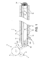
Fig. 1 represents a plan schematic view of an oven-blowing machine assembly according to the invention; -
Fig. 2 represents a perspective partial view of the system for spacing and transferring objects according to the invention; -
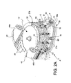
Fig. 2A represents a view of a detail of the system of -
Fig. 2 , according to a different embodiment; -
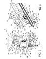
Fig. 3 represents a perspective view of a detail showing a mandrel of the system ofFig. 2 ; -
Fig. 4 represents a different perspective view of a particular detail showing the mandrel ofFig. 3 in a different operative position; -
Fig. 5 represents a side view according to the direction A ofFig. 4 ; -
Fig. 6 represents a side view secondo the direction B ofFig. 4 ; -
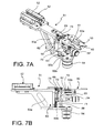
Fig. 7A shows a perspective view of the particular of a plier of the system for spacing and transferring objects of the invention; -
Fig. 7B shows a side view of the plier ofFig. 7A ; -
Fig. 8 shows a perspective view of the particular of the pliers support according to the invention; -
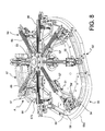
Fig. 9 shows a perspective view of a different embodiment of the system for spacing and transferring objects according to the invention; -
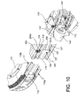
Fig. 10 shows a perspective view of a particular of the embodiment ofFig. 9 ; -
Fig. 11 shows a perspective view of a different detail of the embodiment ofFig. 9 . - The following description relates to a specific embodiment of the system for spacing and transferring objects according to the invention, i.e., the application of the system to an oven for softening the preforms to be sent to a blowing machine. However, is has to be understood that the system of the invention is applicable to other equipment where it is necessary to change the pitch of objects in a predetermined path. With reference to the Figures, an oven for preforms according to an aspect of the invention is indicated with the number 1, which oven is operatively connected with handling means 2, 3 of the preforms, entering and exiting the oven 1, respectively.
- Such handling means 2, 3 are typically composed of distribution stars comprising a series of gripping means 4, for example, notches or recesses, adapted to engage the preforms, for example, at the neck.
- The handling means 3 for the preforms exiting the oven 1 are in turn operatively connected with a blowing machine 5 (the term "blowing machine" as used in the present description means any type of blowing or stretch-blowing machine) that comprises a plurality of moulds 6 in which the heated preform is inserted and from which it comes out in the shape of a blow molded bottle (or stretch-blown) bottle.
- The blowing
machine 5 is in turn operatively connected with distribution means 7, typically a distribution star, adapted to draw the blow moulded bottles exiting the blowing machine and to transfer them, by a suitable transport system, to the next operative unit. To this aim, thedistribution star 7 comprises a plurality of notches 4' adapted to engage the neck of the blow moulded bottles. - A path of the preforms is thus defined, which is indicated in
Fig. 1 by the directions of the arrows, from their supply to the oven 1 to entering thereof the moulds 6 of the blowingmachine 5. - The oven 1 comprises transport means 8, adapted to handle the preforms along a path inside the same oven, and heating means 9.
- The heating means 9 are composed of a plurality of
heating modules 10 aligned along the preform path, typically outside the transport means 8.Such heating modules 10 comprise, for example, one or more infrared lamps and suitable reflective surfaces to optimize the lamp efficiency. - The transport means 8 comprise a
track 11 on which a plurality ofmandrels 12 runs, each being adapted to engage a preform. Thetrack 11 comprises two substantially parallelrectilinear lengths 13, 13' and twocurvilinear lengths 14, 14', connecting at the two ends therectilinear lengths 13, 13' according to an arc-of-circle-shaped path. Correspondingdriving wheels 15, 15' are arranged at saidcurvilinear lengths 14, 14', as it will be best described herein below. - The
track 11 comprises a pair ofrails curvilinear lengths track 11. - The
rails rack bar 17a, 17b forming a side of the L, and aguide bar track 11, therack bars 17a, 17b of therails corresponding guide bars - The
rack bars 17a, 17b comprise, on therectilinear lengths 13, 13' of thetrack 11, adouble rack profile 19 separated by agroove 20, while a single rack is present on thecurvilinear lengths 14, 14'. Such single rack is made of an elastically deformable material, such as, for example, polyurethane. - The guide bars 18a, 18b have a
wedge profile 21 at their top. - The first driving
wheel 15 is arranged in a distal position to the feeding point of the preforms in the oven 1, while the second driving wheel 15' is arranged at the release point of the heated preforms from the oven and in a position proximal to the feeding point of the preforms into the oven. - Each
driving wheels 15, 15' comprises two pairs of discs. - The first
driving wheel 15 comprises a pair oflower discs 22a and a pair ofupper discs 22b, arranged respectively in an lower and an upper position with respect to therails curvilinear length 14 of thetrack 11. The two pairs of lower andupper discs vertical shaft 23, which is mounted idle on a suitable support (not shown). - The pair of
lower discs 22a comprises a first and asecond discs 24, 24', the second disc 24' being spaced apart above thefirst disc 24, by means ofsuitable spacers 25, and having a diameter lower than that of thefirst disc 24. - Both the first and the
second discs 24, 24' of the pair oflower discs 22a comprise, along the perimeter thereof, a plurality ofsemicircular recesses 26 arranged in sequence, so that therecesses 26 of thefirst disc 24 are radially aligned with therecesses 26 of the second disc 24'. - The pair of
upper discs 22b comprises a first and asecond discs 24", 24"', thesecond disc 24"' being spaced apart above thefirst disc 24", by means ofsuitable spacers 25, and having a diameter larger than that of thefirst disc 24". In particular, thesecond disc 24"' of the pair ofupper discs 22b has the same diameter of thefirst disc 24 of the pair oflower discs 22a, while thefirst disc 24" of the pair ofupper discs 22b has the same diameter of the second disc 24' of the pair oflower discs 22a. - Both the first and the
second disc 24", 24"' of the pair ofupper discs 22b comprise, along the perimeter thereof, a plurality ofsemicircular recesses 26 arranged in sequence, so that therecesses 26 of thefirst disc 24" are radially aligned with therecesses 26 of thesecond disc 24"' and with therecesses 26 of both the first and thesecond discs 24, 24' of the pair oflower discs 22a. - Similarly, the second driving wheel 15' comprises a pair of
lower discs 27a and a pair ofupper discs 27b, arranged in the lower and upper position, respectively, with respect to therails track 11. The lower 27a and upper 27 pairs of discs of the second driving wheel 15' are completely similar to those of thefirst driving wheel 15 described above, except in that thesemicircular recesses 26 are arranged at an angular distance one to the other that corresponds to the pitch of the notches 4 of thedistribution star 3 for the heated preforms. - Each of the
mandrels 12 comprises ahousing 28 integrally associated to a slidingsupport 29. - The sliding
support 29 comprises afork bar 30 with a C profile, astride thetrack 11. Saidfork bar 30 comprises avertical plate 30a, from the two ends of which, twoarms toothed wheels 31, 31' are rotatably associated to thevertical plate 30a, which are arranged along a vertical axis between the rack bars 17a, 17b of therails racks 19 of the corresponding bars. Each of thetoothed wheels 31, 31' is composed of two coaxial toothed pinions, arranged so as to mesh together and with thedouble racks 19 that are present on the rectilinear lengths of the rails. Vice versa, at the curvilinear lengths, only the outermost toothed pinion meshes with the single rack (seeFig. 3 ). - Furthermore, two
cylindrical bearings vertical plate 30a, at thearms 30b, 30c. Saidbearings groove 33 arranged along the cylindrical surface thereof, adapted to engage in rotation with thecorresponding guide bars - The
arms mandrel 12, that are adapted to engage with therecesses 26 of thediscs wheels 15, 15'. - Such guide means comprise a first pair of
guide rollers 34 rotatably mounted in the proximity of the distal end of thearms guide rollers 34 is intended to interfere with therecesses 26 of the second disc 24' of the pair oflower discs first disc 24" of the pair ofupper discs wheels 15, 15'. - The guide means further comprise a second pair of
guide rollers 35 rotatably mounted on opposite faces of thearms arms vertical plate 30a. The second pair ofguide rollers 35 is intended to interfere with therecesses 26 of thefirst disc 24 of the pair oflower discs second disc 24"' of the pair ofupper discs wheels 15, 15'. - Coaxially to the
guide roller 35 arranged on theupper arm 30b, a pushingroller 36 is rotatably mounted. The function of such pushingroller 36 will be apparent in the following of the present description. - The
housing 28 of themandrel 12 houses agripping finger 37 for a preform P (shown inFig. 3 ). The grippingfinger 37 has a diameter slightly lesser than the inner diameter of the preform P and comprises, on the distal portion of the outer surface thereof, an engaging portion 37' comprising in turn one or moreannular reliefs 38 promoting the engagement with the inner neck of the preform. For example,such reliefs 38 are made of an elastic material, such as an elastomer, or they are composed of elastic sectors that are able to reenter or to radially expand with respect to the cylindrical surface of thegripping finger 37, exerting a holding pressure on the preform inner surface. - The gripping
finger 37 further comprises astem 39 that is inserted in thehousing 28 and that is mobile vertically. A drivenmember 40 is associated to thestem 39, which externally protrudes from thehousing 28 through aslot 41 arranged vertically on thehousing 28 body. Such drivenmember 40 typically comprises a roller adapted to interact with a cam profile (not shown), which allows lifting or lowering the grippingfinger 37, so as to disengage or engage, respectively, the inside of the preform P neck. - A
coil spring 42 is arranged on thestem 39 and abuts against ashoulder 43 in the proximity of the engaging portion 37' of thegripping finger 37.Such spring 42 promotes the elastic return downwardly of thegripping finger 37. - The transport means 8 of the oven 1 further comprise handling and spacing means of the
mandrels 12. Such handling means comprise afirst screw 44a arranged at the feeding point of the preforms in the oven, between the driving wheel 15' and a firstrectilinear length 13 of thetrack 11; and asecond screw 44b arranged at the junction point between the second rectilinear length 13' of thetrack 11 and the same driving wheel 15'. Bothscrews spiral slot 45 with variable pitch intended to interfere with the pushingroller 36 of eachmandrel 12. Thescrews mandrels 12, so that thefirst screw 44a has the larger pitch upstream along the running direction, while thesecond screw 44b has the larger pitch downstream. - The
screws - The second driving wheel 15', which, as stated, has a structure similar to the
first driving wheel 15, further comprises a plurality ofpliers 50 adapted to engage the neck of the preforms P exiting the oven and to transfer them to the handling means 3. - The
pliers 50 are arranged below the driving wheel 15' and are mounted on slide means 51 that allow theplier 50 extending radially with respect to the driving wheel 15'. - The slide means 51 comprise a sliding
portion 52 and asupport portion 53. - The sliding
portion 52 comprises a closed C-shaped profile member 52' adapted to slide along a suitable guide, as it will be described herein below. - The
support portion 53 comprises apartitioning element 53a protruding downwardly and at the lower end of which abase plate 53b is secured. On the lower face of the base plate, a first drivenmember 54 is arranged, typically a driving roller or double driving roller mounted idle with a vertical rotational axis. Furthermore, thesupport portion 53 houses the opening-closing mechanism of theplier 50, comprising twojaws recess 60 for the object to be handled, a preform in the described case. Thejaws small plate 62 and comprise, below suchsmall plate 62, corresponding small tabs 63 (in the drawing, only the one relative to thejaw 50b is shown) connected byelastic means 61, typically a spiral spring. The opening of thejaws jaws recess 60, to subsequently snap close. The transferring of the preform from theplier 50 to the handling means 3 occurs in the same manner, but in an inverse direction. - The
small plate 62 is secured on ahousing 70, which, in turn comprises a slidingmember 69 associated to avertical guide 68 secured to the front surface of thepartitioning element 53a. - The
housing 70 has a hole in which avertical support shaft 71 is inserted. Thesupport shaft 71 is held between thebase plate 53b at the bottom and a holdingplate 73 at the top. - Around the
support shaft 71, compression elastic means 72 are located, typically a spiral spring, abutting inferiorly against an internal shoulder of thehousing 70 and superiorly on the holdingplate 73. In this manner, theplier 50 can slide in the vertical direction between thebase plate 53b and the holdingplate 73. When theplier 50 is in the raised position, the elastic means 72 are loaded. - On the
housing 70, also a second driven member 54' is secured, typically a driving roller or a double driving roller mounted idle with horizontal rotational axis, protruding outwardly of theplier 50 in the longitudinal direction. - In
Fig. 8 is shown the assembly of thepliers 50 mounted on aguide structure 64. - The
guide structure 64 comprises ahub 65, intended to be mounted below the driving wheel 15' so as to rotate integrally thereto, from which a plurality of guide bars 66 extends radially, on which the closed C-shaped profile members 52' of thepliers 50 are slidably mounted. Thepliers 50 are thus located at a distance that corresponds to the pitch of the gripping means 4 of the handling means 3. - The support structure (not shown) of the system for spacing and transferring objects supports a
first cam profile 55, 55'. Thefirst cam profile 55, 55' is located in a fixed, yet removable, manner below the second driving wheel 15', at the corresponding curvilinear length 14' of thetrack 11. Thecam profile 55, 55' is adapted to cooperate with the first drivenmember 54 of thepliers 50, determining the path thereof. - The
cam profile 55, 55' comprises acurvilinear path 58 running at a lower level than the level where the first drivenmember 54 is located at the gripping point A of the preform P by theplier 50. - A
second cam profile 67 is located at the gripping point A of the preform by theplier 50, and it is intended to cooperate with the second driven member 54' of theplier 50. Thesecond cam profile 67 comprises an initial raised length 57a and a terminal loweredlength 57b, so as to lower theplier 50 to such a level that the first drivenmember 54 is brought to cooperate with thecurvilinear path 58 of thefirst cam profile 55, 55'. Such movement of theplier 50 is allowed by the sliding along thevertical guide 68. In this manner, theplier 50, once it couples the preform P, lowers, thus allowing the disengagement of the preform from the grippingfinger 37 of themandrel 12. - The
cam profile 55, 55' as stated is removable, so as to be interchangeable according to the various needs. - In a first embodiment shown in
Fig. 2 , thecam profile 55 describes an arc of a circle with the same radius of curvature of the driving wheel 15', whereby thepliers 50 will follow the same path of themandrels 12. - In a second embodiment, shown in
Fig. 2A and8 , the cam profile 55' has at least one intermediate length with radius of curvature lower than that of the driving wheel 15', so as to form a protrudingportion 56 in radial direction with respect to the driving wheel 15'. Such protrudingportion 56 comprises a point ofmaximum extent 56a that corresponds to the position of maximum extent of theplier 50 and that is generally at the intermediate point of the path. - The operation of the system for spacing and transferring objects according to the invention, referred to the example of the oven described above, is as follows.
- The preforms are fed to the oven 1 by means of the
distribution star 2 shown inFig. 1 . At the feeding point, or in an upstream position, themandrels 12, pushed by thefirst screw 44a and mobile in procession along thetrack 11 in contact with each other, interfere, through the drivenmember 40 thereof, with a suitable cam profile. In this manner, the grippingfinger 37 is raised from the cam, then subsequently lowered, by virtue of the return by thespring 42, so as to insert in the neck of the preform P and to engage therewith. From this moment, eachmandrel 12 carries a preform that is held in suspension. - Subsequently, the
mandrels 12 with the preforms pass through thevarious heating modules 10 of the firstrectilinear length 13 and, always being pushed by thefirst screw 44a, they are driven by thedriving wheel 15 passing to the second rectilinear length 13' of thetrack 11, where the preforms are further heated by theother heating modules 10, until reaching the proper softening temperature of the material. - At this point, the
mandrels 12 with the softened preforms, when they have reached thesecond screw 44b, interfere with the correspondinggroove 45 through the pushingroller 36. Considered that thegroove 45 has a variable increasing pitch, themandrels 12, which come in contact to one another, are spaced by a larger pitch that corresponds to the pitch of thenotches 26 of the driving wheel 15'. Such pitch can be equal to or lower than that of the notches 4 of thedistribution star 3. At the point A shown inFig. 2A , amandrel 12 incoming, carrying a preform P, is at aplier 50, which provides to couple the preform P. Thesecond cam profile 67 with which the second driven member 54' of theplier 50 cooperates, causes a lowering of the plier just downstream of the point A, so as to disengage the preform P from the grippingfinger 37 of themandrel 12. - Subsequently, the
plier 50 carrying the preform P, moving integrally to the driving wheel 15', follows the path dictated by thefirst cam profile 55, 55', up to the point (not shown) in which the preform P is given by theplier 50 to thedistribution star 3. This point will be usually located at the intermediate point of the path of the plier. - The path dictated by the
cam profile 55, 55', as stated, varies according to the needs. In particular, in the embodiment shown inFig. 2A , the cam profile 55' carries theplier 50 to extend up to thepoint 56a in which the transfer of the preform P from theplier 50 to the distribution star will occur. - In this manner, a transfer of the preform P is carried out in perfectly homokinetic conditions. In particular, the preform P is subjected to a first linear acceleration upon the spacing carried out by the
screw 44b, and a second radial acceleration at the extension thereof, carried out by theplier 50 up to thetransferring point 56a. Subsequently, the two components of the acceleration are divided into separate steps, and moreover they occur gradually. These operative conditions are optimal in order to reduce the mechanical stress that the softened preform P must undergo, thus preventing it from being deformed. Themandrels 12 without the preforms and spaced at the larger pitch are then driven by the driving wheel 15' up to thefirst screw 44a. The latter, having agroove 45 with a decreasing pitch in the running direction of themandrels 12, brings them back to the condition of minimum pitch, and pushes them along thetrack 11 to be in contact with one another. - In the
Figs. 9-11 , a second embodiment of the system for spacing and transferring objects of the invention is shown. - The system of the invention comprises transport means 108. The transport means 108 comprise a
track 111 on which a plurality ofmandrels 112 runs, each being adapted to engage an object, a preform in this example. Thetrack 111 comprises two substantially parallelrectilinear lengths 113, 113' and twocurvilinear lengths 114, 114' connecting at the two ends therectilinear lengths 113, 113' according to an arc-of-circle-shaped path. Corresponding drivingwheels 115, 115' are arranged at saidcurvilinear lengths 114, 114', as it will be best described herein below. - The
track 111 comprises a pair of vertically alignedrails curvilinear lengths track 111. - Each
rail profiles gap 119. - The
first driving wheel 115 is arranged in the distal position with respect to the feeding point of the objects in the system, while the second driving wheel 115' is arranged at the output point of the objects and in a position proximal to the feeding point of the objects in the system. - The driving
wheels 115, 115' comprise anupper disc lower disc rails curvilinear length 114 of thetrack 111. - The upper 122a, 127a and lower 122b, 127b discs are associated to corresponding vertical shafts 123 mounted idle on a suitable support (not shown). Both the
lower disc upper disc second driving wheels 115, 115' comprise along the perimeter thereof a plurality ofsemicircular recesses 126 arranged in sequence, so that therecesses 126 in the two overlapping discs are aligned. However, in the second driving wheel 115', thesemicircular recesses 126 are arranged at an angular distance one to the other that is larger and corresponding to the pitch of thegripping means 3 of the handling means 4. - Each of the
mandrels 112 comprises acylindrical body 200, at the two ends of which, anupper flange member 201a and alower flange member 201b are arranged. Eachflange member upper profiles 117, 117' and with the pair oflower profiles 118, 118', respectively. To this aim, the length of thecylindrical body 200 of themandrel 112 corresponds to the distance between thelower rail 116a and theupper rail 116b, while the diameter of the circular groove is substantially corresponding to thegap 119. In this manner, themandrel 112 is longitudinally held, and the inclination thereof in each direction is prevented. At the same time, themandrel 112 is free to rotate idle. At the upper end of themandrel 112, atoothed roller 202 is secured, which is intended to interact with suitable racks within the oven, so as to rotate and to subsequently allow an even distribution of the heat throughout the preform surface. In a system for spacing and transferring that is not applied to a preform oven, this member may be omitted. - The lower end of the
mandrel 112 comprises agripping finger 137, completely similar to that described above with reference to the first embodiment. Thegripping finger 137 is, for example, adapted to interfere with the neck of a preform, but it will be able to be replaced in other applications by da suitable engaging means. - The transport means 108 further comprise handling and spacing means of the
mandrels 112. Such handling and spacing means comprise at least one pair ofscrews 144', 144" arranged at the junction point between the second rectilinear length 113' of thetrack 111 and the driving wheel 115'. - The two
screws 144', 144" are arranged side by side, but they are arranged on planes that are offset in height, so that the superiorly arranged one interacts with thecylindrical body 200 of themandrel 112 below the pair ofprofiles 118, 118', while the inferiorly arranged one interacts with the samecylindrical body 200 of themandrel 112 above the pair ofprofiles 117, 117', so that, during the accelerative transients, themandrel 112 is stabilized in all directions due to the action of the combined constraint of the screws and of a portion of theguide screws 144', 144" substantially corresponds to the diameter of saidflange members mandrel 112. - Both
screws 144', 144" comprise aspiral slot 145 with variable pitch composing the screw reactive surface. Bothscrews 144', 144" have the larger pitch downstream along the running direction. - The
screws 144', 144" can be moved independently, but in a synchronized manner by corresponding motorizations (not shown), or by a single motorization provided with a mechanical transmission. - A second pair of screws can be present at the feeding point of the objects in the transport means 108, i.e., between the driving wheel 115' and the first
rectilinear length 113. - A plurality of
pliers 50 is associated to the driving wheel 115', which pliers are mobile along acam profile 55, 55' completely similar to that described with reference to the first embodiment, to which complete reference is made. - Although the above-described embodiments of the invention have been provided for handling, spacing and transferring of preforms heated within a oven, typically an infrared oven for preforms, it shall be apparent that the system for spacing and transferring that is the object of the invention can be applied to other equipment that require to handle object and to distance them at a preset pitch, there being applications that are generally known in the packaging field.
- Therefore, an object of the present invention is a system as defined in claim 1. A further object of the invention is a method as defined in claim 18.
- With the term "gradual linear acceleration" or "gradual radial acceleration" is meant a non-instantaneous linear or radial acceleration, i.e. which occurs in a time lapse that is sufficiently long as not to cause a dynamic stress to the transported object.
- In a preferred embodiment, the handling means 3 are a distribution star and the objects are preforms or containers.
- The advantages of this solution are many.
- First of all, the described system allows maximizing the efficiency of the transport means and reducing to a minimum the overall dimensions, since the mandrels proceed in contact to one another, thus at the minimum possible distance. When applied to a preform oven, the heat dispersion is reduced to a minimum and energy efficiency is maximized.
- Furthermore, the
mandrels 12 are not directly connected to transport means, but they are pushed by the twoscrews - On the other hand, the guide system that comprises the
toothed wheels 31, 31' engaging on thedouble rack bars 17a, 17b, as well as theguide rollers recesses 26 of the drivingwheels 15, 15', allows an efficient control of themandrels 12 position, throughout the path, with respect to longitudinal or transversal oscillations thereabout of the same mandrel. - The
bearings corresponding guide bars mandrels 12. - The fact that the
cam profile 55, 55' is interchangeable, allows carrying out an homokinetic transferring as described above, independently from the pitch, the dimension, or the rotation speed of the distribution star intended to receive and transfer the objects, specifically the heated preforms, simply suitably selecting the path. - This allows avoiding the deformation of the preforms that, as stated above, may have undesired effects on the final result of the blowing operation.
- The advantages of an homokinetic transferring of the objects and the spacing thereof in the absence of accelerative stresses, by virtue of the fact of separating the linear acceleration from the radial acceleration, and by virtue of the fact that such accelerations occur gradually, is a further important advantage of the system of the invention.
- It shall be apparent that only some particular embodiments of the present invention have been described, to which those skilled in the art will be able to make all those modifications that are necessary for the adaption thereof to particular applications, without for this departing from the protection scope of the present invention as defined by the appended claims.
- For example, in an embodiment, the
bearings corresponding guide bars mandrels 12.
Claims (18)
- A system for spacing and transferring of objects advancing in procession on transport means (8, 108) along a track (11, 111) from a minimum pitch to a preset pitch larger than said minimum pitch, and for transferring said spaced objects to handling means (3), wherein said system comprises a driving wheel (15', 115'), said driving wheel (15', 115') comprising a plurality of recesses (26, 126) for driving a plurality of mandrels (12, 112), each mandrel (12, 112) carrying one of said objects, the recesses (26, 126) being spaced by a pitch larger than said minimum pitch of the objects in the transport means (8, 108), said pitch of the recesses (26, 126) being equal to or lower than said preset pitch, characterized in that the system comprises:- handling and spacing means (44b; 144', 144") of the mandrels (12, 112) carrying the objects from said minimum pitch to a pitch substantially corresponding to the pitch of the recesses (26, 126), the said handling and spacing means (44b; 144', 144") being arranged at the junction point between a rectilinear length (13', 113') of the track (11, 111) and the driving wheel (15', 115'); and- a plurality of pliers (50) that are mounted on a guide structure (64) arranged below the driving wheel (15', 115') and rotating integrally thereto, the pliers (50) being radially extendible from the driving wheel (15', 115'), said pliers (50) being driven by a cam profile (55, 55') that determines the path of said pliers (50), said pliers (50) being adapted to engage the said objects carried by the mandrels (12, 112) and to transfer the objects to said handling means (3).
- The system according to claim 1, wherein said objects are preforms (P) transported by mandrels (12, 112), and wherein said transport means (8, 108) are located in an oven (1) for heating and treating the thermal profile of preforms (P).
- The system according to claim 1 or 2, wherein the pliers (50) are mounted on slide means (51) allowing the plier (50) to radially extend with respect to the driving wheel (15', 115').
- The system according to claim 3, wherein the guide structure (64) comprises a hub (65), intended to be mounted below the driving wheel (15') so as to rotate integrally thereto, from which a plurality of guide bars (66) radiates; and wherein the slide means (51) comprise a sliding portion (52) and a support portion (53), the sliding portion (52) comprising a closed C-shaped profile member (52') adapted to slide along one of said guide bars (66); and wherein the support portion (53) comprises a driven member (54).
- The system according to claim 4, wherein said driven member (54) is a driving roller mounted idle with a vertical rotational axis.
- The system according to any of claims 3 to 5, wherein said pliers (50) are mobile vertically with respect to said slide means (51), wherein the plier (50) is associated to a member (69) sliding in a vertical guide (68) secured to the support portion (53), so that the plier (50) can slide vertically abutting against compression elastic means (72); and wherein the plier (50) comprises a second driven member (54') protruding outwardly of the plier (50) in the longitudinal direction.
- The system according to claim 6, wherein the second driven member (54') is a one or a double driving roller mounted idle with a horizontal rotational axis.
- The system according to any one of the claims 1 to 7, wherein a first cam profile (55, 55') is located in a fixed, yet removable, manner below the second driving wheel (15', 115'), said first cam profile (55, 55') being adapted to cooperate with the first driven member (54) of the pliers (50).
- The system according to claim 8, wherein said first cam profile (55, 55') comprises a curvilinear path (58) running at a lower level than the level in which the first driven member (54) is located at the gripping point (A) of an object by the plier (50).
- The system according to any one of the claims 1 to 9, wherein the first cam profile (55) describes an arc of a circle with the same radius of curvature of the driving wheel (15', 115'); or wherein the first cam profile (55') has at least one intermediate length with a radius of curvature lower than that of the driving wheel (15', 115'), so as to form a protruded portion (56) in the radial direction with respect to the driving wheel (15', 115'), said protruding portion (56) comprising a point of maximum extent (56a) corresponding to the position of maximum extent of the plier (50) at the transferring point of the object from the oven to the handling means (3).
- The system according to any one of the claims 1 to 10, comprising a second cam profile (67) located at the gripping point (A) of an object by a plier (50), said second cam profile (67) being intended to cooperate with the second driven member (54') of the plier (50), wherein the second cam profile (67) comprises an initial raised length (57a) and a terminal lowered length (57b), so as to lower the plier (50) to such a level that the first driven member (54) is brought to cooperate with the curvilinear path (58) of the first cam profile (55, 55').
- The system according to claim 1, wherein the track (11) comprises a pair of rails (16a, 16b) arranged one above the other, wherein the rails (16a, 16b) comprise rack bars (17a, 17b) facing one another.
- The system according to claim 12, wherein each of the mandrels (12) comprises a housing (28) integrally associated to a sliding support (29), the sliding support (29) comprising a fork bar (30) with a C-shaped profile astride the track (11), and comprises two toothed wheels (31, 31'), arranged along a vertical axis between the rack bars (17a, 17b) of the rails (16a, 16b), so as to mesh with one another and with the racks (19) of the corresponding bars, and wherein each of the toothed wheels (31, 31') is composed of two coaxial toothed pinions, arranged so as to mesh with the double racks (19) that are present on the rectilinear lengths of the rails.
- The system according to any one of the claims 1 to 11, wherein the track (111) comprises two substantially parallel rectilinear lengths (113, 113') and two curvilinear lengths (114, 114') connecting at the two ends the rectilinear lengths (113, 113') according to an arc-of-circle-shaped path, corresponding driving wheels (115, 115') being arranged at said curvilinear lengths (114, 114').
- The system according to claim 14, wherein the track (111) comprises a pair of vertically aligned rails (116a, 116b), each in turn being divided into rectilinear lengths and curvilinear lengths at the rectilinear and curvilinear lengths (113, 113', 114, 114') of the track (111), each rail (116a, 116b) being formed by a pair of profiles (117, 117', 118, 118') that are arranged side by side and separated by a gap (119).
- The system according to claim 14 or 15, wherein each of the mandrels (112) comprises a cylindrical body (200), at the two ends of which an upper flange member (201a) and a lower flange member (201b) are arranged, wherein each flange member (201a, 201b) defines a circular groove intended to cooperate with the pair of lower profiles (117, 117') and with the pair of upper profiles (118, 118'), respectively, the diameter of the circular groove being substantially corresponding to the gap (119); the lower end of the mandrel (112) further comprising a gripping finger (137).
- The system according to any one of the claims 14 to 16, wherein said handling and spacing means (144', 144") of the objects comprise a pair of screws (144', 144") arranged at the junction point between the second rectilinear length (113') of the track (111) and the driving wheel (115'), the screws (144', 144") comprising a spiral slot (145) having a variable pitch composing the reactive surface of the screw having the larger pitch downstream along the running direction; wherein said screws (144', 144") are arranged side by side, but on planes that are offset in height, so that the superiorly arranged one interacts with the cylindrical body (200) of the mandrel (112) below the pair of upper profiles (118, 118'), while the inferiorly arranged one interacts with the same cylindrical body (200) above the pair of lower profiles (117, 117').
- A method using the system of claim 1 for spacing objects advancing in procession on transport means (8, 108) from a minimum pitch to a preset pitch larger than said minimum pitch and for transferring said spaced objects to handling means (3), comprising:- a linear spacing step along said transport means (8, 108), wherein an object is subjected to a gradual linear acceleration,- a radial spacing step along said transport means (8, 108) between a first circumference and a second circumference having a radius that is larger than or equal to said first circumference, wherein said object is subjected to a gradual radial acceleration,- a transferring step from said transport means (8, 108) to said handling means (3), wherein said transferring occurs in homokinetic conditions.
Applications Claiming Priority (1)
| Application Number | Priority Date | Filing Date | Title |
|---|---|---|---|
| IT000991A ITMI20120991A1 (en) | 2012-06-07 | 2012-06-07 | SYSTEM OF DISTANCE AND TRANSFER OF OBJECTS BETWEEN OPERATING STATIONS |
Publications (2)
| Publication Number | Publication Date |
|---|---|
| EP2671704A1 EP2671704A1 (en) | 2013-12-11 |
| EP2671704B1 true EP2671704B1 (en) | 2015-06-24 |
Family
ID=46582934
Family Applications (1)
| Application Number | Title | Priority Date | Filing Date |
|---|---|---|---|
| EP13170667.3A Active EP2671704B1 (en) | 2012-06-07 | 2013-06-05 | System for spacing and transferring objects between operative stations |
Country Status (5)
| Country | Link |
|---|---|
| US (1) | US9039405B2 (en) |
| EP (1) | EP2671704B1 (en) |
| CA (1) | CA2818054C (en) |
| ES (1) | ES2548273T3 (en) |
| IT (1) | ITMI20120991A1 (en) |
Families Citing this family (15)
| Publication number | Priority date | Publication date | Assignee | Title |
|---|---|---|---|---|
| ITMI20111762A1 (en) * | 2011-09-30 | 2013-03-31 | Smi Spa | PREFORM OVEN APPLICABLE WITH BLOWING MACHINES OR STYROSOFFERING MACHINES |
| EP2889238A1 (en) * | 2013-12-31 | 2015-07-01 | Sidel S.p.a. Con Socio Unico | Transfer device for transferring articles along a path |
| CN104760264B (en) * | 2015-04-16 | 2024-04-05 | 临海市大格格兰压缩机有限公司 | Continuous uninterrupted bottle blank interval adjusting mechanism of bottle blowing machine |
| FR3035651B1 (en) * | 2015-04-29 | 2017-04-21 | Sidel Participations | "METHOD FOR CONTROLLING HOLLOW BODY CONVEYOR THROUGH HEATING STATION AND ASSOCIATED CONVEYOR" |
| DE102017004232A1 (en) * | 2017-05-02 | 2018-11-08 | Seidenader Maschinenbau Gmbh | Object transport device |
| DE102017215455A1 (en) * | 2017-09-04 | 2019-03-07 | Krones Ag | Transport device for transporting pucks |
| IT201800003400A1 (en) * | 2018-03-09 | 2019-09-09 | Smi Spa | PREFORM OVEN |
| CN112693099B (en) * | 2020-12-09 | 2022-07-26 | 霸州市萱源塑料制品有限公司 | Heating and air-blowing molding integrated plastic bottle manufacturing device |
| DE102021134504A1 (en) * | 2021-12-23 | 2023-06-29 | Krones Aktiengesellschaft | Device and method for treating and in particular sterilizing containers |
| DE102021134499A1 (en) | 2021-12-23 | 2023-06-29 | Krones Aktiengesellschaft | Device and method for treating and in particular sterilizing containers |
| DE102021134507A1 (en) | 2021-12-23 | 2023-06-29 | Krones Aktiengesellschaft | Device and method for treating and in particular sterilizing containers |
| DE102021134529A1 (en) | 2021-12-23 | 2023-06-29 | Krones Aktiengesellschaft | Device and method for treating and in particular sterilizing containers |
| DE102021134514A1 (en) | 2021-12-23 | 2023-06-29 | Krones Aktiengesellschaft | Device and method for treating and in particular sterilizing containers |
| CN117067557B (en) * | 2023-08-23 | 2024-05-28 | 湖北铭达塑胶制品有限公司 | Blank unloading mechanism of bottle blowing machine |
| CN118358965B (en) * | 2024-06-19 | 2024-08-13 | 四川圣亚凯紧固器材有限公司 | Injection molding nail feeding device |
Family Cites Families (6)
| Publication number | Priority date | Publication date | Assignee | Title |
|---|---|---|---|---|
| US3565235A (en) * | 1968-09-27 | 1971-02-23 | Anchor Hocking Corp | Conveyor transfer apparatus |
| IT1145100B (en) * | 1981-10-23 | 1986-11-05 | Risvin Ricerche Sviluppo Ind | METHOD AND DEVICE FOR THE HANDLING OF PRODUCTS BY MEANS OF OPERATING VEHICLES CARRIED IN CONTINUOUS MOVEMENT |
| US4753275A (en) * | 1985-03-27 | 1988-06-28 | Schaltegger Herbert E | Method and apparatus for high speed container placement |
| DE19727278A1 (en) * | 1997-02-17 | 1999-01-07 | Kronseder Maschf Krones | Blow molding machine |
| IT1396467B1 (en) * | 2008-07-29 | 2012-12-14 | Sacmi | PLANT FOR BLOWING PLASTIC CONTAINERS, BOTTLES IN PARTICULAR |
| DE102008037865A1 (en) * | 2008-08-15 | 2010-02-18 | Anton Jazbinsek | Transport device has transport pitch of retaining device for objects, particularly preforms or blanks for plastic material container, where plastic material container has driving unit and circumferential feed stroke |
-
2012
- 2012-06-07 IT IT000991A patent/ITMI20120991A1/en unknown
-
2013
- 2013-06-05 ES ES13170667.3T patent/ES2548273T3/en active Active
- 2013-06-05 EP EP13170667.3A patent/EP2671704B1/en active Active
- 2013-06-05 CA CA2818054A patent/CA2818054C/en active Active
- 2013-06-06 US US13/911,101 patent/US9039405B2/en active Active
Also Published As
| Publication number | Publication date |
|---|---|
| ES2548273T3 (en) | 2015-10-15 |
| US20130330437A1 (en) | 2013-12-12 |
| CA2818054A1 (en) | 2013-12-07 |
| ITMI20120991A1 (en) | 2013-12-08 |
| US9039405B2 (en) | 2015-05-26 |
| CA2818054C (en) | 2021-04-13 |
| EP2671704A1 (en) | 2013-12-11 |
Similar Documents
| Publication | Publication Date | Title |
|---|---|---|
| CA2818054C (en) | System for spacing and transferring objects between operative stations | |
| US8851881B2 (en) | Ovens for preforms | |
| CN104309102B (en) | Machines for treating containers group | |
| EP1410894B1 (en) | Apparatus for moulding wide mouthed containers | |
| EP2639189B1 (en) | Processing unit, blowmoulding apparatus with such unit and rotary machine with a plurality of such units | |
| CN104369353B (en) | Apparatus and method for heating plastic preforms | |
| CN102431150A (en) | Transport device for prefabricated piece | |
| CN105358303B (en) | Conveying device | |
| US8425220B2 (en) | Moulding unit for a plant for blow-moulding plastic containers, particularly bottles | |
| US7771188B2 (en) | Device for gripping the neck of hollow bodies and hollow body transport installation which is equipped with such devices | |
| EP3549744B1 (en) | Oven for preforms | |
| EP3202691B1 (en) | Molded-article supply apparatus | |
| US10427350B2 (en) | Preform handling device, and blow forming device | |
| CN109414868A (en) | Heating equipment for the blow moulding machine with folding conveyer chain | |
| EP3536481B1 (en) | Oven for preforms | |
| US6787096B2 (en) | Device for treating preforms to obtain containers made of plastics | |
| RU2789144C2 (en) | Furnace for heating of preforms | |
| EP4378863A1 (en) | Rotating starwheel device with variable opening/closing grippers | |
| AU701692B2 (en) | Apparatus for manufacturing containers by blow moulding plastic preforms |
Legal Events
| Date | Code | Title | Description |
|---|---|---|---|
| PUAI | Public reference made under article 153(3) epc to a published international application that has entered the european phase |
Free format text: ORIGINAL CODE: 0009012 |
|
| AK | Designated contracting states |
Kind code of ref document: A1 Designated state(s): AL AT BE BG CH CY CZ DE DK EE ES FI FR GB GR HR HU IE IS IT LI LT LU LV MC MK MT NL NO PL PT RO RS SE SI SK SM TR |
|
| AX | Request for extension of the european patent |
Extension state: BA ME |
|
| 17P | Request for examination filed |
Effective date: 20140227 |
|
| RBV | Designated contracting states (corrected) |
Designated state(s): AL AT BE BG CH CY CZ DE DK EE ES FI FR GB GR HR HU IE IS IT LI LT LU LV MC MK MT NL NO PL PT RO RS SE SI SK SM TR |
|
| GRAP | Despatch of communication of intention to grant a patent |
Free format text: ORIGINAL CODE: EPIDOSNIGR1 |
|
| INTG | Intention to grant announced |
Effective date: 20150121 |
|
| GRAS | Grant fee paid |
Free format text: ORIGINAL CODE: EPIDOSNIGR3 |
|
| GRAA | (expected) grant |
Free format text: ORIGINAL CODE: 0009210 |
|
| AK | Designated contracting states |
Kind code of ref document: B1 Designated state(s): AL AT BE BG CH CY CZ DE DK EE ES FI FR GB GR HR HU IE IS IT LI LT LU LV MC MK MT NL NO PL PT RO RS SE SI SK SM TR |
|
| REG | Reference to a national code |
Ref country code: GB Ref legal event code: FG4D |
|
| REG | Reference to a national code |
Ref country code: CH Ref legal event code: EP |
|
| REG | Reference to a national code |
Ref country code: AT Ref legal event code: REF Ref document number: 732705 Country of ref document: AT Kind code of ref document: T Effective date: 20150715 |
|
| REG | Reference to a national code |
Ref country code: IE Ref legal event code: FG4D |
|
| REG | Reference to a national code |
Ref country code: DE Ref legal event code: R096 Ref document number: 602013002066 Country of ref document: DE |
|
| REG | Reference to a national code |
Ref country code: ES Ref legal event code: FG2A Ref document number: 2548273 Country of ref document: ES Kind code of ref document: T3 Effective date: 20151015 |
|
| PG25 | Lapsed in a contracting state [announced via postgrant information from national office to epo] |
Ref country code: HR Free format text: LAPSE BECAUSE OF FAILURE TO SUBMIT A TRANSLATION OF THE DESCRIPTION OR TO PAY THE FEE WITHIN THE PRESCRIBED TIME-LIMIT Effective date: 20150624 Ref country code: FI Free format text: LAPSE BECAUSE OF FAILURE TO SUBMIT A TRANSLATION OF THE DESCRIPTION OR TO PAY THE FEE WITHIN THE PRESCRIBED TIME-LIMIT Effective date: 20150624 Ref country code: LT Free format text: LAPSE BECAUSE OF FAILURE TO SUBMIT A TRANSLATION OF THE DESCRIPTION OR TO PAY THE FEE WITHIN THE PRESCRIBED TIME-LIMIT Effective date: 20150624 Ref country code: NO Free format text: LAPSE BECAUSE OF FAILURE TO SUBMIT A TRANSLATION OF THE DESCRIPTION OR TO PAY THE FEE WITHIN THE PRESCRIBED TIME-LIMIT Effective date: 20150924 |
|
| REG | Reference to a national code |
Ref country code: AT Ref legal event code: MK05 Ref document number: 732705 Country of ref document: AT Kind code of ref document: T Effective date: 20150624 |
|
| REG | Reference to a national code |
Ref country code: LT Ref legal event code: MG4D |
|
| PG25 | Lapsed in a contracting state [announced via postgrant information from national office to epo] |
Ref country code: GR Free format text: LAPSE BECAUSE OF FAILURE TO SUBMIT A TRANSLATION OF THE DESCRIPTION OR TO PAY THE FEE WITHIN THE PRESCRIBED TIME-LIMIT Effective date: 20150925 Ref country code: RS Free format text: LAPSE BECAUSE OF FAILURE TO SUBMIT A TRANSLATION OF THE DESCRIPTION OR TO PAY THE FEE WITHIN THE PRESCRIBED TIME-LIMIT Effective date: 20150624 Ref country code: LV Free format text: LAPSE BECAUSE OF FAILURE TO SUBMIT A TRANSLATION OF THE DESCRIPTION OR TO PAY THE FEE WITHIN THE PRESCRIBED TIME-LIMIT Effective date: 20150624 Ref country code: BG Free format text: LAPSE BECAUSE OF FAILURE TO SUBMIT A TRANSLATION OF THE DESCRIPTION OR TO PAY THE FEE WITHIN THE PRESCRIBED TIME-LIMIT Effective date: 20150924 |
|
| REG | Reference to a national code |
Ref country code: NL Ref legal event code: MP Effective date: 20150624 |
|
| PG25 | Lapsed in a contracting state [announced via postgrant information from national office to epo] |
Ref country code: EE Free format text: LAPSE BECAUSE OF FAILURE TO SUBMIT A TRANSLATION OF THE DESCRIPTION OR TO PAY THE FEE WITHIN THE PRESCRIBED TIME-LIMIT Effective date: 20150624 |
|
| PG25 | Lapsed in a contracting state [announced via postgrant information from national office to epo] |
Ref country code: PL Free format text: LAPSE BECAUSE OF FAILURE TO SUBMIT A TRANSLATION OF THE DESCRIPTION OR TO PAY THE FEE WITHIN THE PRESCRIBED TIME-LIMIT Effective date: 20150624 Ref country code: AT Free format text: LAPSE BECAUSE OF FAILURE TO SUBMIT A TRANSLATION OF THE DESCRIPTION OR TO PAY THE FEE WITHIN THE PRESCRIBED TIME-LIMIT Effective date: 20150624 Ref country code: SK Free format text: LAPSE BECAUSE OF FAILURE TO SUBMIT A TRANSLATION OF THE DESCRIPTION OR TO PAY THE FEE WITHIN THE PRESCRIBED TIME-LIMIT Effective date: 20150624 Ref country code: PT Free format text: LAPSE BECAUSE OF FAILURE TO SUBMIT A TRANSLATION OF THE DESCRIPTION OR TO PAY THE FEE WITHIN THE PRESCRIBED TIME-LIMIT Effective date: 20151026 Ref country code: CZ Free format text: LAPSE BECAUSE OF FAILURE TO SUBMIT A TRANSLATION OF THE DESCRIPTION OR TO PAY THE FEE WITHIN THE PRESCRIBED TIME-LIMIT Effective date: 20150624 Ref country code: RO Free format text: LAPSE BECAUSE OF NON-PAYMENT OF DUE FEES Effective date: 20150624 Ref country code: IS Free format text: LAPSE BECAUSE OF FAILURE TO SUBMIT A TRANSLATION OF THE DESCRIPTION OR TO PAY THE FEE WITHIN THE PRESCRIBED TIME-LIMIT Effective date: 20151024 |
|
| REG | Reference to a national code |
Ref country code: DE Ref legal event code: R097 Ref document number: 602013002066 Country of ref document: DE |
|
| PG25 | Lapsed in a contracting state [announced via postgrant information from national office to epo] |
Ref country code: IT Free format text: LAPSE BECAUSE OF FAILURE TO SUBMIT A TRANSLATION OF THE DESCRIPTION OR TO PAY THE FEE WITHIN THE PRESCRIBED TIME-LIMIT Effective date: 20150624 Ref country code: DK Free format text: LAPSE BECAUSE OF FAILURE TO SUBMIT A TRANSLATION OF THE DESCRIPTION OR TO PAY THE FEE WITHIN THE PRESCRIBED TIME-LIMIT Effective date: 20150624 |
|
| PLBE | No opposition filed within time limit |
Free format text: ORIGINAL CODE: 0009261 |
|
| STAA | Information on the status of an ep patent application or granted ep patent |
Free format text: STATUS: NO OPPOSITION FILED WITHIN TIME LIMIT |
|
| 26N | No opposition filed |
Effective date: 20160329 |
|
| REG | Reference to a national code |
Ref country code: FR Ref legal event code: PLFP Year of fee payment: 4 |
|
| PG25 | Lapsed in a contracting state [announced via postgrant information from national office to epo] |
Ref country code: SI Free format text: LAPSE BECAUSE OF FAILURE TO SUBMIT A TRANSLATION OF THE DESCRIPTION OR TO PAY THE FEE WITHIN THE PRESCRIBED TIME-LIMIT Effective date: 20150624 |
|
| PG25 | Lapsed in a contracting state [announced via postgrant information from national office to epo] |
Ref country code: BE Free format text: LAPSE BECAUSE OF FAILURE TO SUBMIT A TRANSLATION OF THE DESCRIPTION OR TO PAY THE FEE WITHIN THE PRESCRIBED TIME-LIMIT Effective date: 20150624 |
|
| PG25 | Lapsed in a contracting state [announced via postgrant information from national office to epo] |
Ref country code: MC Free format text: LAPSE BECAUSE OF FAILURE TO SUBMIT A TRANSLATION OF THE DESCRIPTION OR TO PAY THE FEE WITHIN THE PRESCRIBED TIME-LIMIT Effective date: 20150624 |
|
| REG | Reference to a national code |
Ref country code: CH Ref legal event code: PL |
|
| REG | Reference to a national code |
Ref country code: IE Ref legal event code: MM4A |
|
| PG25 | Lapsed in a contracting state [announced via postgrant information from national office to epo] |
Ref country code: CH Free format text: LAPSE BECAUSE OF NON-PAYMENT OF DUE FEES Effective date: 20160630 Ref country code: LI Free format text: LAPSE BECAUSE OF NON-PAYMENT OF DUE FEES Effective date: 20160630 |
|
| PG25 | Lapsed in a contracting state [announced via postgrant information from national office to epo] |
Ref country code: IE Free format text: LAPSE BECAUSE OF NON-PAYMENT OF DUE FEES Effective date: 20160605 |
|
| PG25 | Lapsed in a contracting state [announced via postgrant information from national office to epo] |
Ref country code: NL Free format text: LAPSE BECAUSE OF FAILURE TO SUBMIT A TRANSLATION OF THE DESCRIPTION OR TO PAY THE FEE WITHIN THE PRESCRIBED TIME-LIMIT Effective date: 20150624 Ref country code: SE Free format text: LAPSE BECAUSE OF FAILURE TO SUBMIT A TRANSLATION OF THE DESCRIPTION OR TO PAY THE FEE WITHIN THE PRESCRIBED TIME-LIMIT Effective date: 20150624 |
|
| REG | Reference to a national code |
Ref country code: FR Ref legal event code: PLFP Year of fee payment: 5 |
|
| PG25 | Lapsed in a contracting state [announced via postgrant information from national office to epo] |
Ref country code: SM Free format text: LAPSE BECAUSE OF FAILURE TO SUBMIT A TRANSLATION OF THE DESCRIPTION OR TO PAY THE FEE WITHIN THE PRESCRIBED TIME-LIMIT Effective date: 20150624 Ref country code: CY Free format text: LAPSE BECAUSE OF FAILURE TO SUBMIT A TRANSLATION OF THE DESCRIPTION OR TO PAY THE FEE WITHIN THE PRESCRIBED TIME-LIMIT Effective date: 20150624 Ref country code: HU Free format text: LAPSE BECAUSE OF FAILURE TO SUBMIT A TRANSLATION OF THE DESCRIPTION OR TO PAY THE FEE WITHIN THE PRESCRIBED TIME-LIMIT; INVALID AB INITIO Effective date: 20130605 |
|
| PG25 | Lapsed in a contracting state [announced via postgrant information from national office to epo] |
Ref country code: MK Free format text: LAPSE BECAUSE OF FAILURE TO SUBMIT A TRANSLATION OF THE DESCRIPTION OR TO PAY THE FEE WITHIN THE PRESCRIBED TIME-LIMIT Effective date: 20150624 Ref country code: MT Free format text: LAPSE BECAUSE OF NON-PAYMENT OF DUE FEES Effective date: 20160630 Ref country code: LU Free format text: LAPSE BECAUSE OF NON-PAYMENT OF DUE FEES Effective date: 20160605 Ref country code: TR Free format text: LAPSE BECAUSE OF FAILURE TO SUBMIT A TRANSLATION OF THE DESCRIPTION OR TO PAY THE FEE WITHIN THE PRESCRIBED TIME-LIMIT Effective date: 20150624 |
|
| REG | Reference to a national code |
Ref country code: FR Ref legal event code: PLFP Year of fee payment: 6 |
|
| PG25 | Lapsed in a contracting state [announced via postgrant information from national office to epo] |
Ref country code: AL Free format text: LAPSE BECAUSE OF FAILURE TO SUBMIT A TRANSLATION OF THE DESCRIPTION OR TO PAY THE FEE WITHIN THE PRESCRIBED TIME-LIMIT Effective date: 20150624 |
|
| PGFP | Annual fee paid to national office [announced via postgrant information from national office to epo] |
Ref country code: DE Payment date: 20250624 Year of fee payment: 13 |
|
| PGFP | Annual fee paid to national office [announced via postgrant information from national office to epo] |
Ref country code: GB Payment date: 20250618 Year of fee payment: 13 |
|
| PGFP | Annual fee paid to national office [announced via postgrant information from national office to epo] |
Ref country code: FR Payment date: 20250530 Year of fee payment: 13 |
|
| PGFP | Annual fee paid to national office [announced via postgrant information from national office to epo] |
Ref country code: ES Payment date: 20250701 Year of fee payment: 13 |