EP2671547A1 - Hearing protection - Google Patents
Hearing protection Download PDFInfo
- Publication number
- EP2671547A1 EP2671547A1 EP13169778.1A EP13169778A EP2671547A1 EP 2671547 A1 EP2671547 A1 EP 2671547A1 EP 13169778 A EP13169778 A EP 13169778A EP 2671547 A1 EP2671547 A1 EP 2671547A1
- Authority
- EP
- European Patent Office
- Prior art keywords
- aperture
- sound attenuating
- sound
- apertures
- present disclosure
- Prior art date
- Legal status (The legal status is an assumption and is not a legal conclusion. Google has not performed a legal analysis and makes no representation as to the accuracy of the status listed.)
- Granted
Links
Images


Classifications
-
- A—HUMAN NECESSITIES
- A61—MEDICAL OR VETERINARY SCIENCE; HYGIENE
- A61F—FILTERS IMPLANTABLE INTO BLOOD VESSELS; PROSTHESES; DEVICES PROVIDING PATENCY TO, OR PREVENTING COLLAPSING OF, TUBULAR STRUCTURES OF THE BODY, e.g. STENTS; ORTHOPAEDIC, NURSING OR CONTRACEPTIVE DEVICES; FOMENTATION; TREATMENT OR PROTECTION OF EYES OR EARS; BANDAGES, DRESSINGS OR ABSORBENT PADS; FIRST-AID KITS
- A61F11/00—Methods or devices for treatment of the ears or hearing sense; Non-electric hearing aids; Methods or devices for enabling ear patients to achieve auditory perception through physiological senses other than hearing sense; Protective devices for the ears, carried on the body or in the hand
- A61F11/06—Protective devices for the ears
- A61F11/14—Protective devices for the ears external, e.g. earcaps or earmuffs
Definitions
- the present disclosure relates to hearing protection.
- Employers should be seeking protection, suited to the work and working environment, but not 'over protecting' (i.e. aiming to avoid protected levels of less than 70 dB).
- a protector providing attenuation equal to the minimum requirements would produce, according to standard methods and for the majority of the population, protected levels around or below the low to mid 70s (depending on the characteristics of the noise). Protected levels transpose correspondingly to higher or lower ambient levels.
- one hearing protection device includes a first material, having sound attenuating characteristics, shaped to cover over an ear of a user; at least one aperture formed in the first material; and a second material positioned over the aperture.
- Such embodiments may provide better protection for the user, for example, by not overprotecting in the 80-90 dB range or underprotecting at lower frequencies (e.g., up to 500 Hz).
- Figure 1 illustrates a hearing protector in accordance with one or more embodiments of the present disclosure.
- the device 100 includes a first material 102 having a number of apertures 104, a second material 106 wherein a portion of the second material 106 is positioned over the apertures 104, a third material 110, and a weight 108. These components will be discussed in more detail below.
- the first material portion 102 has sound attenuating characteristics and is shaped to cover over an ear of a user.
- the third material portion 110 can be formed from any suitable material. As shown in the embodiment of Figure 1 , such devices typically include one portion that is shaped to fit over one ear and another portion shaped to fit over the other ear with a strap running between them that fits over a user's head or around the user's neck.
- other suitable structures for attaching hearing protection can be utilized with the embodiments of the present disclosure.
- the device 100 also includes a third material 110 positioned on a first side of the first material 102.
- the third material portion 110 can be formed from any suitable material.
- a suitable material is foam.
- the device can have just first and second material portions. As illustrated in the embodiment of Figure 1 , this first material can be a housing of the hearing protector.
- the first material can be an ear cover portion of the body of the device.
- the body can have multiple portions that provide different sound attention at different decibel ranges.
- a first portion of the body can provide sound attenuation at a first decibel range.
- a second portion can be designed to provide a sound attenuation at a second decibel range.
- the first portion may include a first sound attenuating material and, in some embodiments, a second sound attenuating material (e.g., first and second materials 102 and 106 of Figure 1 ).
- the first portion may include an aperture. The use of the aperture changes the sound attenuation characteristics of the first portion with respect to the sound attenuation characteristics of the second portion.
- the device can be designed to attenuate sound that could be harmful to a user, but allow the user to hear other sounds, such as a project manager giving the user instructions.
- the sound attenuation of the device can be tuned (e.g., during and/or after manufacture, in various embodiments) for different applications where the sound environment may be different and need attenuation at different ranges.
- first and third materials can be directly adjacent to one another or in some embodiments, the materials may have one or more layers provided between them, however, such structures do not affect the scope of the present disclosure.
- the device 100 includes one or more apertures 104 formed in the first material 102.
- the device has three apertures, however, embodiments of the present disclosure can have any number of apertures.
- the apertures can be of any suitable size.
- the diameter, interior shape, and/or depth of the aperture are characteristics that can be utilized to change the sound attenuation characteristics of the aperture.
- an aperture of a first diameter may have different attenuation characteristics than one having a second diameter (i.e., larger or smaller).
- the device can have multiple apertures and the apertures can be of different sizes, shapes, and/or depths.
- changes in interior shape can include a change in the shape of any side, top and/or bottom surface of the aperture (i.e., interior cavity formed by the first, second, and/or third materials).
- the device includes multiple apertures formed in at least the first material and at least two of the apertures have different diameters. Such an embodiment will be discussed in more detail below with regard to Figures 2A and 2B .
- the device also includes a second material that is positioned over the apertures 104 (e.g., applied on one side surface of the first material 102).
- the material is a thin film 106 that is applied over the surface of the first material 102 and extends over all three apertures provided.
- different materials can be used to cover one or more of the apertures.
- materials having different attenuation characteristics could be used over different apertures.
- Attenuation characteristics include: type of material, thickness, permeability, and flexibility, uniformity of the thickness across the aperture, among others. Such characteristics can be selected to change the sound attenuation of each aperture and, therefore, the device can be tuned to best attenuate sound in particular applications, in some embodiments.
- the second material can be integral with the first material.
- the second and first materials could be formed or bonded together.
- the second material can be removable from the first material and/or replaceable, thereby allowing the sound attenuation characteristics of the device to be changed (or each aperture, in some embodiments) by either removing the material or replacing one piece of material with another piece of material that has one or more different characteristics than the one that was removed.
- the sound attenuating characteristics of one material can be different from one or more of the other materials.
- the second material has sound attenuating characteristics that are different from the sound attenuating characteristics of the first material.
- the third material can have sound attenuating characteristics that are different from the sound attenuating characteristics of the first material, in some embodiments. And, in various such embodiments, the third material can have sound attenuating characteristics that are different from the sound attenuating characteristics of the second material.
- a weight can be used to change the attenuating characteristics of the second material (and, thereby, the aperture). For instance, by attaching a weight to the second material, it changes the material's ability to resonate.
- the weight can be any suitable shape and can be fabricated from any suitable material.
- the weight can be fabricated from the same material as the second material (e.g., a polymer material). Further, the weight can be affixed to the surface of the second material that is inside the aperture, or can be positioned on the other side of the second material, such that the weight is outside the aperture.
- the weight can be removable and/or replaceable, such that the device can be tuned through removal of the weight or use of weights that are different in size, shape, weight, and/or material type.
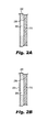
- Figure 2A illustrates a noise attenuating structure in accordance with one or more embodiments of the present disclosure.
- an aperture 204 is illustrated as being formed in a first material 202 and between third material 210 and second material 206.
- This structure acts to form a cavity within the aperture which gives this portion of the device a different set of attenuating characteristics than other portions of the device (e.g., a portion having first, second, and/or third material layers, but no aperture formed therein). As discussed above, this can be a second portion of the device that has different sound attenuating characteristics than a first portion and can include an aperture formed between a foam material and a thin film material.
- Figure 2B illustrates another noise attenuating structure in accordance with one or more embodiments of the present disclosure.
- an aperture 204 is illustrated as being formed in a first material 202 and between third material 210 and second material 206. This structure acts to form a cavity within the aperture which gives this portion of the device a different set of attenuating characteristics than one or more other portions of the device.
- a weight 208 is formed outside of the aperture 204 and defined cavity. However, as discussed above, the weight 208 could be within the aperture and defined cavity, in some embodiments (such as in Figure 1 ).
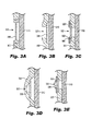
- Figure 3A illustrates another noise attenuating structure in accordance with one or more embodiments of the present disclosure.
- an aperture 322 is illustrated as being formed in a first material 302 and between third material 310 and second material 306. This structure acts to form a cavity within the aperture which gives this portion of the device a different set of attenuating characteristics than one or more other portions of the device.
- the second material 306 is positioned within the aperture that is formed in first material 302.
- the second material can be affixed in any suitable manner, such as, mechanical attachment (as shown in Figure 3A ), and/or adhesive attachment, among other suitable attachment mechanisms.
- the aperture can extend into a third material 310 (if utilized) and the membrane may also be positioned into the third material via the aperture, in some embodiments.
- Figure 3B illustrates another noise attenuating structure in accordance with one or more embodiments of the present disclosure.
- an aperture 322 is illustrated as being formed in a first material 302.
- the second material 306 is positioned over (i.e. extending across) from an inside surface of the first material 302.
- the first material is shaped to form a cavity between third material 310 and second material 306.
- This structure acts to form a cavity, similar in function to that of previous embodiments, which gives this portion of the device a different set of attenuating characteristics than one or more other portions of the device.
- the second material 306 could be positioned over the aperture 322 and attached to the outer surface of the first material 302.
- Figure 3C illustrates another noise attenuating structure in accordance with one or more embodiments of the present disclosure.
- an aperture 322 is illustrated as being formed in a fourth material 320.
- This material can be any suitable material for providing an aperture.
- the second material 306 is positioned over (i.e. extending across) from an inside surface of the fourth material 320. In this embodiment, the second material is positioned between the first material 302 and the fourth material 320, however, the embodiments of the present disclosure are not so limited.
- the first material is shaped to form a cavity between third material 310 and second material 306.
- This structure acts to form a cavity, similar in function to that of previous embodiments, which gives this portion of the device a different set of attenuating characteristics than one or more other portions of the device.
- the second material 306 could be positioned over the aperture 322 and attached to the outer surface of the fourth material 320.
- Figure 3D illustrates another noise attenuating structure in accordance with one or more embodiments of the present disclosure.
- an aperture 322 is illustrated as being formed in a first material 302.
- the second material 306 is positioned over (i.e. extending across) from an inside surface of the first material 302.
- the first material is shaped to form a cavity between third material 310 and second material 306.
- This structure also acts to form two cavities (i.e., a second cavity between first material 302 and second material 306), that are both similar in function to that of previous embodiments, which gives this portion of the device a different set of attenuating characteristics than one or more other portions of the device. Accordingly, it should be understood that multiple cavities may be positioned in a serial arrangement with respect to the sounds entering the device as is illustrated in Figure 3D .
- the second material 306 could be positioned over the aperture 322 and attached to the outer surface of the first material 302.
- Figure 3E illustrates another noise attenuating structure in accordance with one or more embodiments of the present disclosure.
- an aperture 322 is illustrated as being formed in a fourth material 320.
- This material can be any suitable material for providing an aperture.
- the second material 306 is positioned over (i.e. extending across) from an inside surface of the fourth material 320.
- This embodiment provides that, the second material is positioned between the first material 302 and the fourth material 320, however, the embodiments of the present disclosure are not so limited.
- the first material is shaped to form a cavity between third material 310 and second material 306.
- This structure acts to form two cavities, that, as discussed above, are both similar in function to that of previous embodiments, which gives this portion of the device a different set of attenuating characteristics than one or more other portions of the device. Accordingly, it should be understood that multiple cavities may be positioned in a serial arrangement with respect to the sounds entering the device as is illustrated in Figure 3E .
- the second material 306 could be positioned over the aperture 322 and attached to the outer surface of the fourth material 320.
- Figure 4 is a chart illustrating noise attenuation of various structures formed in accordance with one or more embodiments of the present disclosure.
- the chart provides attenuation examples, for devices having no apertures at 418, one aperture at 416, two apertures at 414, and three apertures at 412.
- the more apertures that were provided on the device the generally lower the attenuation of the device at certain sound frequency ranges, such as the 250 to 1300 Hz range, while attenuation at other ranges was not as affected, such as 2300 Hz and higher frequencies.
- the illustrated change at higher frequencies can still be viewed as significant and, in some embodiments, the change at higher frequencies can be even greater than is illustrated in the chart.
- the illustrated embodiments in the chart also provide some sound attenuation at low frequencies which may be an improvement over devices which provide little to no protection at lower frequencies (e.g., up to 500 Hz). Such embodiments can be useful for allowing the user to hear better at some frequency ranges thereby allowing for better overall user safety with hearing protection, in some applications.
Landscapes
- Health & Medical Sciences (AREA)
- Life Sciences & Earth Sciences (AREA)
- Biomedical Technology (AREA)
- Acoustics & Sound (AREA)
- Biophysics (AREA)
- Otolaryngology (AREA)
- Psychology (AREA)
- Engineering & Computer Science (AREA)
- Physics & Mathematics (AREA)
- Heart & Thoracic Surgery (AREA)
- Vascular Medicine (AREA)
- Animal Behavior & Ethology (AREA)
- General Health & Medical Sciences (AREA)
- Public Health (AREA)
- Veterinary Medicine (AREA)
- Soundproofing, Sound Blocking, And Sound Damping (AREA)
Abstract
Description
- The present disclosure relates to hearing protection.
- Changes in legislation, such as arising from European Directive 2003/10/EC, make the use of hearing protection advisory for daily exposures at or above 80 dB, and compulsory where exposures exceed 85 dB. It may be assumed, therefore, that employers may be seeking personal hearing protection for workers in environments where noise levels are in the range 80-90 dB, and that employers are seeking to provide personal hearing protection to workers who have previously not made use of protection.
- Employers should be seeking protection, suited to the work and working environment, but not 'over protecting' (i.e. aiming to avoid protected levels of less than 70 dB).
- When worn in a noise environment of 85 dB, a protector providing attenuation equal to the minimum requirements would produce, according to standard methods and for the majority of the population, protected levels around or below the low to mid 70s (depending on the characteristics of the noise). Protected levels transpose correspondingly to higher or lower ambient levels.
- However, there do not appear to be any devices on the market intended for occupational use, for example, that provide attenuation equal to or close to the minimum requirements described above. As a consequence, the market appears to fail the employer seeking a suitable protector for noise levels in the range 80-90 dB that does not 'overprotect'.
- This overprotection can result in the user being afforded a non-trivial attenuation at low frequencies. Current solutions also may provide underprotection at lower frequencies and overprotection at higher frequencies. For example, some current devices provide almost zero dB attenuation up to 500 HZ and, then, 25 dB attenuation at higher frequencies.
-
-
Figure 1 illustrates a hearing protector in accordance with one or more embodiments of the present disclosure. -
Figure 2A illustrates a noise attenuating structure in accordance with one or more embodiments of the present disclosure. -
Figure 2B illustrates another noise attenuating structure in accordance with one or more embodiments of the present disclosure. -
Figure 3A illustrates another noise attenuating structure in accordance with one or more embodiments of the present disclosure. -
Figure 3B illustrates another noise attenuating structure in accordance with one or more embodiments of the present disclosure. -
Figure 3C illustrates another noise attenuating structure in accordance with one or more embodiments of the present disclosure. -
Figure 3D illustrates another noise attenuating structure in accordance with one or more embodiments of the present disclosure. -
Figure 3E illustrates another noise attenuating structure in accordance with one or more embodiments of the present disclosure. -
Figure 4 illustrates a chart showing the noise attenuation using various embodiments of the present disclosure. - Hearing protection devices are disclosed. For example, one hearing protection device includes a first material, having sound attenuating characteristics, shaped to cover over an ear of a user; at least one aperture formed in the first material; and a second material positioned over the aperture. Such embodiments may provide better protection for the user, for example, by not overprotecting in the 80-90 dB range or underprotecting at lower frequencies (e.g., up to 500 Hz).
- In the following detailed description, reference is made to the accompanying drawings that form a part hereof. The drawings show by way of illustration how one or more embodiments of the disclosure may be practiced. These embodiments are described in sufficient detail to enable those of ordinary skill in the art to practice one or more embodiments of this disclosure. It is to be understood that other embodiments may be utilized and that process, electrical, and/or structural changes may be made without departing from the scope of the present disclosure.
- As will be appreciated, elements shown in the various embodiments herein can be added, exchanged, combined, and/or eliminated so as to provide a number of additional embodiments of the present disclosure. The proportion and the relative scale of the elements provided in the figures are intended to illustrate the embodiments of the present disclosure, and should not be taken in a limiting sense.
- The figures herein follow a numbering convention in which the first digit or digits correspond to the drawing figure number and the remaining digits identify an element or component in the drawing. Similar elements or components between different figures may be identified by the use of similar digits. For example, 104 may reference element "04" in
Figure 1 , and a similar element may be referenced as 204 inFigure 2A . As used herein, "a" or "a number of" something can refer to one or more such things. For example, "a number of apertures" can refer to one or more apertures. -
Figure 1 illustrates a hearing protector in accordance with one or more embodiments of the present disclosure. In the embodiment ofFigure 1 , thedevice 100 includes afirst material 102 having a number ofapertures 104, asecond material 106 wherein a portion of thesecond material 106 is positioned over theapertures 104, athird material 110, and aweight 108. These components will be discussed in more detail below. - In the embodiment of
Figure 1 , thefirst material portion 102 has sound attenuating characteristics and is shaped to cover over an ear of a user. Thethird material portion 110 can be formed from any suitable material. As shown in the embodiment ofFigure 1 , such devices typically include one portion that is shaped to fit over one ear and another portion shaped to fit over the other ear with a strap running between them that fits over a user's head or around the user's neck. However, other suitable structures for attaching hearing protection can be utilized with the embodiments of the present disclosure. - The
device 100 also includes athird material 110 positioned on a first side of thefirst material 102. Thethird material portion 110 can be formed from any suitable material. One example of a suitable material is foam. - However, in some embodiments, the device can have just first and second material portions. As illustrated in the embodiment of
Figure 1 , this first material can be a housing of the hearing protector. For example, the first material can be an ear cover portion of the body of the device. - In embodiments of the present disclosure, the body can have multiple portions that provide different sound attention at different decibel ranges. For example, in some embodiments, a first portion of the body can provide sound attenuation at a first decibel range. A second portion can be designed to provide a sound attenuation at a second decibel range.
- For instance, the first portion may include a first sound attenuating material and, in some embodiments, a second sound attenuating material (e.g., first and
second materials Figure 1 ). In such an embodiment, the first portion may include an aperture. The use of the aperture changes the sound attenuation characteristics of the first portion with respect to the sound attenuation characteristics of the second portion. - One benefit of such an embodiment can be that the device can be designed to attenuate sound that could be harmful to a user, but allow the user to hear other sounds, such as a project manager giving the user instructions. Through use of varied size, shape, and/or depth of the one or more apertures and/or the materials used to construct the portions of the device, the sound attenuation of the device can be tuned (e.g., during and/or after manufacture, in various embodiments) for different applications where the sound environment may be different and need attenuation at different ranges.
- In some embodiments, first and third materials can be directly adjacent to one another or in some embodiments, the materials may have one or more layers provided between them, however, such structures do not affect the scope of the present disclosure.
- The
device 100 includes one ormore apertures 104 formed in thefirst material 102. In the embodiment illustrated inFigure 1 , the device has three apertures, however, embodiments of the present disclosure can have any number of apertures. - Additionally, the apertures can be of any suitable size. In fact, the diameter, interior shape, and/or depth of the aperture are characteristics that can be utilized to change the sound attenuation characteristics of the aperture.
- For example, an aperture of a first diameter may have different attenuation characteristics than one having a second diameter (i.e., larger or smaller). Accordingly, in some embodiments, the device can have multiple apertures and the apertures can be of different sizes, shapes, and/or depths. It should be noted that changes in interior shape can include a change in the shape of any side, top and/or bottom surface of the aperture (i.e., interior cavity formed by the first, second, and/or third materials).
- For example, in some embodiments, the device includes multiple apertures formed in at least the first material and at least two of the apertures have different diameters. Such an embodiment will be discussed in more detail below with regard to
Figures 2A and 2B . - As illustrated in
Figure 1 , and discussed above, the device also includes a second material that is positioned over the apertures 104 (e.g., applied on one side surface of the first material 102). In the embodiment ofFigure 1 , the material is athin film 106 that is applied over the surface of thefirst material 102 and extends over all three apertures provided. - In some embodiments, different materials can be used to cover one or more of the apertures. For example, materials having different attenuation characteristics could be used over different apertures.
- Examples of attenuation characteristics include: type of material, thickness, permeability, and flexibility, uniformity of the thickness across the aperture, among others. Such characteristics can be selected to change the sound attenuation of each aperture and, therefore, the device can be tuned to best attenuate sound in particular applications, in some embodiments.
- In various embodiments, the second material can be integral with the first material. For example the second and first materials could be formed or bonded together.
- In various embodiments, the second material can be removable from the first material and/or replaceable, thereby allowing the sound attenuation characteristics of the device to be changed (or each aperture, in some embodiments) by either removing the material or replacing one piece of material with another piece of material that has one or more different characteristics than the one that was removed.
- In some embodiments, the sound attenuating characteristics of one material can be different from one or more of the other materials. For example, in various embodiments, the second material has sound attenuating characteristics that are different from the sound attenuating characteristics of the first material.
- In embodiments having three materials, the third material can have sound attenuating characteristics that are different from the sound attenuating characteristics of the first material, in some embodiments. And, in various such embodiments, the third material can have sound attenuating characteristics that are different from the sound attenuating characteristics of the second material.
- In some embodiments, such as that illustrated in
Figure 1 , a weight can be used to change the attenuating characteristics of the second material (and, thereby, the aperture). For instance, by attaching a weight to the second material, it changes the material's ability to resonate. The weight can be any suitable shape and can be fabricated from any suitable material. For example, the weight can be fabricated from the same material as the second material (e.g., a polymer material). Further, the weight can be affixed to the surface of the second material that is inside the aperture, or can be positioned on the other side of the second material, such that the weight is outside the aperture. In some embodiments, the weight can be removable and/or replaceable, such that the device can be tuned through removal of the weight or use of weights that are different in size, shape, weight, and/or material type. -
Figure 2A illustrates a noise attenuating structure in accordance with one or more embodiments of the present disclosure. In the embodiment ofFigure 2A , anaperture 204 is illustrated as being formed in afirst material 202 and betweenthird material 210 andsecond material 206. - This structure acts to form a cavity within the aperture which gives this portion of the device a different set of attenuating characteristics than other portions of the device (e.g., a portion having first, second, and/or third material layers, but no aperture formed therein). As discussed above, this can be a second portion of the device that has different sound attenuating characteristics than a first portion and can include an aperture formed between a foam material and a thin film material.
-
Figure 2B illustrates another noise attenuating structure in accordance with one or more embodiments of the present disclosure. In the embodiment ofFigure 2B , anaperture 204 is illustrated as being formed in afirst material 202 and betweenthird material 210 andsecond material 206. This structure acts to form a cavity within the aperture which gives this portion of the device a different set of attenuating characteristics than one or more other portions of the device. - Additionally, a
weight 208 is formed outside of theaperture 204 and defined cavity. However, as discussed above, theweight 208 could be within the aperture and defined cavity, in some embodiments (such as inFigure 1 ). -
Figure 3A illustrates another noise attenuating structure in accordance with one or more embodiments of the present disclosure. In the embodiment ofFigure 3A , anaperture 322 is illustrated as being formed in afirst material 302 and betweenthird material 310 andsecond material 306. This structure acts to form a cavity within the aperture which gives this portion of the device a different set of attenuating characteristics than one or more other portions of the device. - In the embodiment of
Figure 3A , thesecond material 306 is positioned within the aperture that is formed infirst material 302. In such embodiments, the second material can be affixed in any suitable manner, such as, mechanical attachment (as shown inFigure 3A ), and/or adhesive attachment, among other suitable attachment mechanisms. In some embodiments, the aperture can extend into a third material 310 (if utilized) and the membrane may also be positioned into the third material via the aperture, in some embodiments. -
Figure 3B illustrates another noise attenuating structure in accordance with one or more embodiments of the present disclosure. In the embodiment ofFigure 3B , anaperture 322 is illustrated as being formed in afirst material 302. In this embodiment, thesecond material 306 is positioned over (i.e. extending across) from an inside surface of thefirst material 302. The first material is shaped to form a cavity betweenthird material 310 andsecond material 306. - This structure acts to form a cavity, similar in function to that of previous embodiments, which gives this portion of the device a different set of attenuating characteristics than one or more other portions of the device. In some embodiments, the
second material 306 could be positioned over theaperture 322 and attached to the outer surface of thefirst material 302. -
Figure 3C illustrates another noise attenuating structure in accordance with one or more embodiments of the present disclosure. In the embodiment ofFigure 3C , anaperture 322 is illustrated as being formed in afourth material 320. This material can be any suitable material for providing an aperture. - In this embodiment, the
second material 306 is positioned over (i.e. extending across) from an inside surface of thefourth material 320. In this embodiment, the second material is positioned between thefirst material 302 and thefourth material 320, however, the embodiments of the present disclosure are not so limited. - In the embodiment of
Figure 3C , the first material is shaped to form a cavity betweenthird material 310 andsecond material 306. This structure acts to form a cavity, similar in function to that of previous embodiments, which gives this portion of the device a different set of attenuating characteristics than one or more other portions of the device. In some embodiments, thesecond material 306 could be positioned over theaperture 322 and attached to the outer surface of thefourth material 320. -
Figure 3D illustrates another noise attenuating structure in accordance with one or more embodiments of the present disclosure. In the embodiment ofFigure 3D , anaperture 322 is illustrated as being formed in afirst material 302. In this embodiment, thesecond material 306 is positioned over (i.e. extending across) from an inside surface of thefirst material 302. The first material is shaped to form a cavity betweenthird material 310 andsecond material 306. - This structure also acts to form two cavities (i.e., a second cavity between
first material 302 and second material 306), that are both similar in function to that of previous embodiments, which gives this portion of the device a different set of attenuating characteristics than one or more other portions of the device. Accordingly, it should be understood that multiple cavities may be positioned in a serial arrangement with respect to the sounds entering the device as is illustrated inFigure 3D . In some embodiments, thesecond material 306 could be positioned over theaperture 322 and attached to the outer surface of thefirst material 302. -
Figure 3E illustrates another noise attenuating structure in accordance with one or more embodiments of the present disclosure. In the embodiment ofFigure 3E , anaperture 322 is illustrated as being formed in afourth material 320. This material can be any suitable material for providing an aperture. - In this embodiment, the
second material 306 is positioned over (i.e. extending across) from an inside surface of thefourth material 320. This embodiment provides that, the second material is positioned between thefirst material 302 and thefourth material 320, however, the embodiments of the present disclosure are not so limited. - In the embodiment of
Figure 3E , the first material is shaped to form a cavity betweenthird material 310 andsecond material 306. This structure acts to form two cavities, that, as discussed above, are both similar in function to that of previous embodiments, which gives this portion of the device a different set of attenuating characteristics than one or more other portions of the device. Accordingly, it should be understood that multiple cavities may be positioned in a serial arrangement with respect to the sounds entering the device as is illustrated inFigure 3E . In some embodiments, thesecond material 306 could be positioned over theaperture 322 and attached to the outer surface of thefourth material 320. -
Figure 4 is a chart illustrating noise attenuation of various structures formed in accordance with one or more embodiments of the present disclosure. In this figure, the chart provides attenuation examples, for devices having no apertures at 418, one aperture at 416, two apertures at 414, and three apertures at 412. - As can be seen from this set of examples, the more apertures that were provided on the device, the generally lower the attenuation of the device at certain sound frequency ranges, such as the 250 to 1300 Hz range, while attenuation at other ranges was not as affected, such as 2300 Hz and higher frequencies. In some applications, the illustrated change at higher frequencies can still be viewed as significant and, in some embodiments, the change at higher frequencies can be even greater than is illustrated in the chart.
- The illustrated embodiments in the chart also provide some sound attenuation at low frequencies which may be an improvement over devices which provide little to no protection at lower frequencies (e.g., up to 500 Hz). Such embodiments can be useful for allowing the user to hear better at some frequency ranges thereby allowing for better overall user safety with hearing protection, in some applications.
- Although specific embodiments have been illustrated and described herein, those of ordinary skill in the art will appreciate that any arrangement calculated to achieve the same techniques can be substituted for the specific embodiments shown. This disclosure is intended to cover any and all adaptations or variations of various embodiments of the disclosure.
- It is to be understood that the above description has been made in an illustrative fashion, and not a restrictive one. Combination of the above embodiments, and other embodiments not specifically described herein will be apparent to those of skill in the art upon reviewing the above description.
- The scope of the various embodiments of the disclosure includes any other applications in which the above structures and methods are used. Therefore, the scope of various embodiments of the disclosure should be determined with reference to the appended claims, along with the full range of equivalents to which such claims are entitled.
- In the foregoing Detailed Description, various features are grouped together in example embodiments illustrated in the figures for the purpose of streamlining the disclosure. This method of disclosure is not to be interpreted as reflecting an intention that the embodiments of the disclosure require more features than are expressly recited in each claim.
- Rather, as the following claims reflect, inventive subject matter lies in less than all features of a single disclosed embodiment. Thus, the following claims are hereby incorporated into the Detailed Description, with each claim standing on its own as a separate embodiment.
Claims (15)
- A hearing protection device (100), comprising:a first material (102), having sound attenuating characteristics, and shaped, on a first side, to cover over an ear of a user;at least one aperture (104) formed in the first material (102);a second material (106), having sound attenuating characteristics, positioned over the aperture (104); anda third material (110), having sound attenuating characteristics, positioned on a first side of the first material (102).
- The device (100) of claim 1, wherein the device (100) includes a weight (208) attached to the second material (106) and positioned over the aperture (104).
- The device (100) of claim 1, wherein the device (100) includes a weight (208) attached to the second material (106) and positioned between the third material (110) and the second material (106).
- The device (100) of claim 1, wherein the weight (208) is removable from the second material (106).
- The device (100) of claim 1, wherein the device (100) includes multiple apertures (104) formed in the first material (102) and wherein at least two of the apertures (104) have different diameters.
- The device (100) of claim 1, wherein the device (100) includes multiple apertures (104) formed in the first material (102) and wherein the apertures (104) are formed between the second material (106) and another material.
- The device (100) of claim 6, wherein the other material is the third material (110).
- A hearing protection device (100), comprising:an ear covering body, shaped on a first side, to cover over an ear of a user;the body having a first portion providing sound attenuation at a first decibel range;a second portion providing a sound attenuation at a second decibel range; anda third sound attenuating material (110).
- The device (100) of claim 8, wherein the second portion includes an aperture (104) formed between two different materials.
- The device (100) of claim 8, wherein the second portion includes an aperture (104) formed between a foam material and a thin film material.
- The device (100) of claim 8, wherein the second portion includes a first sound attenuating material (102), an aperture (104) formed in a second sound attenuating material (106) and third sound attenuating material (110).
- The device (100) of claim 8, wherein the first portion includes a first sound attenuating material (102) and a second sound attenuating material (106).
- A hearing protection device (100), comprising:a first material (102), having sound attenuating characteristics, shaped to cover over an ear of a user;at least one aperture (104) formed in the first material (102); anda second material (106) positioned over the aperture (104),
wherein said sound attenuating characteristics are different from the sound attenuating characteristics of the first material (102). - The device (100) of claim 13, wherein the second material (106) is applied over a side of the first material (102).
- The device (100) of claim 13, wherein the second material (106) is a thin film material or membrane.
Applications Claiming Priority (1)
| Application Number | Priority Date | Filing Date | Title |
|---|---|---|---|
| US13/488,565 US8651229B2 (en) | 2012-06-05 | 2012-06-05 | Hearing protection |
Publications (2)
| Publication Number | Publication Date |
|---|---|
| EP2671547A1 true EP2671547A1 (en) | 2013-12-11 |
| EP2671547B1 EP2671547B1 (en) | 2022-05-11 |
Family
ID=48577511
Family Applications (1)
| Application Number | Title | Priority Date | Filing Date |
|---|---|---|---|
| EP13169778.1A Active EP2671547B1 (en) | 2012-06-05 | 2013-05-29 | Hearing protection |
Country Status (2)
| Country | Link |
|---|---|
| US (1) | US8651229B2 (en) |
| EP (1) | EP2671547B1 (en) |
Cited By (3)
| Publication number | Priority date | Publication date | Assignee | Title |
|---|---|---|---|---|
| CN108778202A (en) * | 2016-03-29 | 2018-11-09 | 富士胶片株式会社 | Earmuff |
| WO2019111214A1 (en) * | 2017-12-08 | 2019-06-13 | 3M Innovative Properties Company | A hearing protector having a unidirectional sound inlet |
| WO2019179941A1 (en) * | 2018-03-19 | 2019-09-26 | Happy Ears Ab | Hearing protection ear cup assembly |
Families Citing this family (12)
| Publication number | Priority date | Publication date | Assignee | Title |
|---|---|---|---|---|
| US8857563B1 (en) | 2013-07-29 | 2014-10-14 | The Boeing Company | Hybrid acoustic barrier and absorber |
| US8869933B1 (en) | 2013-07-29 | 2014-10-28 | The Boeing Company | Acoustic barrier support structure |
| US9089761B2 (en) * | 2013-09-03 | 2015-07-28 | Matmusic Llc | Wrestling headgear with integrated headphones |
| DE102014207705A1 (en) * | 2014-04-24 | 2015-10-29 | Siemens Aktiengesellschaft | Hearing protection device and a magnetic resonance device with the hearing protection device |
| USD752017S1 (en) * | 2015-01-15 | 2016-03-22 | Isaac Daniel Group, Inc. | Convertible smart headphones with speakers and mood sensors |
| USD840977S1 (en) * | 2017-05-12 | 2019-02-19 | Guizhou Laccess Technology Industry Ltd. | Headset |
| USD857656S1 (en) * | 2017-08-29 | 2019-08-27 | Sennheiser Communications A/S | Headset with adjustable contact pressure (ACP) including a spring system |
| USD890129S1 (en) * | 2018-08-01 | 2020-07-14 | Suyun Liu | Headphone |
| USD854514S1 (en) * | 2019-01-31 | 2019-07-23 | Shenzhen Qianhai Patuoxun Network And Technology Co., Ltd | Headphone |
| US12403034B2 (en) | 2019-01-31 | 2025-09-02 | Flotherm, Inc. | Sleeve-based body temperature regulation |
| CN112887859A (en) * | 2019-11-30 | 2021-06-01 | 华为技术有限公司 | Ear pad, ear muff part and earphone |
| US12502308B2 (en) | 2021-07-01 | 2025-12-23 | Flotherm, Inc. | Flexible heating pads |
Citations (2)
| Publication number | Priority date | Publication date | Assignee | Title |
|---|---|---|---|---|
| GB1276498A (en) * | 1968-08-01 | 1972-06-01 | Amplivox Ltd | Improvements in and relating to ear defenders |
| DE3119260A1 (en) * | 1980-05-14 | 1982-06-09 | Racal Acoustics Ltd., London | Ear protection |
Family Cites Families (38)
| Publication number | Priority date | Publication date | Assignee | Title |
|---|---|---|---|---|
| US2672864A (en) * | 1951-07-18 | 1954-03-23 | Makara Frank | Audio mask |
| US2782423A (en) * | 1954-01-18 | 1957-02-26 | Lockheed Aircraft Corp | Noise attenuating ear protectors |
| US3117575A (en) * | 1961-08-22 | 1964-01-14 | Ross M Carrell | Ear protector |
| US3506981A (en) * | 1968-05-29 | 1970-04-21 | Kenneth C Stewart | Noise absorbing earmuffs |
| US3602329A (en) * | 1970-01-07 | 1971-08-31 | Columbia Broadcasting Systems | Conformal ear enclosure |
| US3842829A (en) * | 1971-11-18 | 1974-10-22 | C Ellis | Ear protective device |
| US3795014A (en) * | 1972-05-04 | 1974-03-05 | Fibre Metal Prod Co | Ear protector |
| SE372704B (en) * | 1973-05-16 | 1975-01-13 | Gullfiber Ab | |
| SE389604B (en) * | 1973-12-21 | 1976-11-15 | Gullfiber Ab | COMFORT COLLAR FOR ORONKAPOR |
| US3944018A (en) * | 1974-08-01 | 1976-03-16 | Rodney Jene Satory | Acoustical seal |
| JPS51129217A (en) * | 1975-05-06 | 1976-11-10 | Victor Co Of Japan Ltd | Headphone |
| US4037273A (en) * | 1975-06-20 | 1977-07-26 | Labaire Wallace F | Ear protector |
| US4103359A (en) * | 1977-02-28 | 1978-08-01 | Arcair Company | Noise suppressing welding helmet |
| AT348051B (en) * | 1977-04-15 | 1979-01-25 | Akg Akustische Kino Geraete | CLOSED HEADPHONES |
| GB2075849B (en) * | 1980-05-14 | 1984-03-28 | Racal Acoustics Ltd | Improvements in or relating to hearing protectors |
| GB8308484D0 (en) * | 1983-03-28 | 1983-05-05 | Racal Safety Ltd | Hearing protectors |
| SE450337B (en) * | 1985-03-25 | 1987-06-22 | Bilsom Ab | ORONKAPA INCLUDING SEALING RINGS WITH LIQUID LAYERS |
| AT383930B (en) * | 1985-11-18 | 1987-09-10 | Akg Akustische Kino Geraete | EAR PADS FOR HEADPHONES |
| US4670911A (en) * | 1986-09-26 | 1987-06-09 | Skiears, Inc. | Attachable ear covering for sport activities |
| US4924502A (en) * | 1987-05-08 | 1990-05-08 | Allen Clayton H | Means for stabilizing sound pressure produced at the eardrum under an earpad |
| US4807612A (en) * | 1987-11-09 | 1989-02-28 | Industrial Research Products, Inc. | Passive ear protector |
| SE500417C2 (en) * | 1990-11-02 | 1994-06-20 | Peltor Ab | Ear cover for ear protectors or headphones |
| JP3154214B2 (en) * | 1992-09-25 | 2001-04-09 | ソニー株式会社 | headphone |
| SE505203C2 (en) | 1995-02-01 | 1997-07-14 | Bilsom Ab | A method for changing the sound attenuation of an earmuff as well as the earmuff according to the method |
| CN1190993C (en) * | 1997-04-17 | 2005-02-23 | 伯斯有限公司 | Acoustic noise reducing |
| US5996123A (en) * | 1998-10-16 | 1999-12-07 | Bacon Usa Safety, Inc. | Earmuff for noise blocking |
| US6353938B1 (en) * | 2001-05-10 | 2002-03-12 | Moldex-Metric, Inc. | Sound attenuating earmuff |
| US20050126845A1 (en) | 2003-12-10 | 2005-06-16 | Vaudrey Michael A. | Attenuating foam insert and method for manufacture |
| US7395898B2 (en) * | 2004-03-05 | 2008-07-08 | Rsm Technologies Limited | Sound attenuating structures |
| US7245735B2 (en) * | 2004-04-02 | 2007-07-17 | David Han | Earmuff structure for headset or ear protector |
| SE528345C2 (en) * | 2004-06-16 | 2006-10-24 | Howard Leight Ind Llc | Cover intended to be used as a hearing protector, ways of producing the same and use of such a cover |
| US7240765B2 (en) * | 2004-08-25 | 2007-07-10 | Phonak Ag | Customized hearing protection earplug with an acoustic filter and method for manufacturing the same |
| JP2008025472A (en) * | 2006-07-21 | 2008-02-07 | Denso Corp | Noise reduction device |
| EP2127469A2 (en) * | 2006-12-04 | 2009-12-02 | Adaptive Technologies, Inc. | Sound-attenuating earmuff having isolated double-shell structure |
| US7717226B2 (en) * | 2008-02-20 | 2010-05-18 | Kimberly-Clark Worldwide, Inc. | Hearing protection cap |
| US20090223738A1 (en) * | 2008-02-22 | 2009-09-10 | Yamaha Corporation | Sound absorbing structure and vehicle component having sound absorption property |
| US8249285B2 (en) * | 2009-06-26 | 2012-08-21 | Etymotic Research Inc. | Method and apparatus for producing non linear sound attenuation |
| TW201133468A (en) * | 2010-03-31 | 2011-10-01 | Ind Tech Res Inst | An unit with sound isolation/shock isolation structure, array employing the same, and method for fabricating the same |
-
2012
- 2012-06-05 US US13/488,565 patent/US8651229B2/en active Active
-
2013
- 2013-05-29 EP EP13169778.1A patent/EP2671547B1/en active Active
Patent Citations (2)
| Publication number | Priority date | Publication date | Assignee | Title |
|---|---|---|---|---|
| GB1276498A (en) * | 1968-08-01 | 1972-06-01 | Amplivox Ltd | Improvements in and relating to ear defenders |
| DE3119260A1 (en) * | 1980-05-14 | 1982-06-09 | Racal Acoustics Ltd., London | Ear protection |
Cited By (5)
| Publication number | Priority date | Publication date | Assignee | Title |
|---|---|---|---|---|
| CN108778202A (en) * | 2016-03-29 | 2018-11-09 | 富士胶片株式会社 | Earmuff |
| EP3437595A4 (en) * | 2016-03-29 | 2019-04-10 | FUJIFILM Corporation | Earmuff |
| WO2019111214A1 (en) * | 2017-12-08 | 2019-06-13 | 3M Innovative Properties Company | A hearing protector having a unidirectional sound inlet |
| US11744738B2 (en) | 2017-12-08 | 2023-09-05 | 3M Innovative Properties Company | Hearing protector having a unidirectional sound inlet |
| WO2019179941A1 (en) * | 2018-03-19 | 2019-09-26 | Happy Ears Ab | Hearing protection ear cup assembly |
Also Published As
| Publication number | Publication date |
|---|---|
| US8651229B2 (en) | 2014-02-18 |
| US20130319788A1 (en) | 2013-12-05 |
| EP2671547B1 (en) | 2022-05-11 |
Similar Documents
| Publication | Publication Date | Title |
|---|---|---|
| US8651229B2 (en) | Hearing protection | |
| EP0092362B1 (en) | Nonlinear passive acoustic filtering | |
| EP2843915B1 (en) | Headset communication method under loud-noise environment and headset | |
| US7717226B2 (en) | Hearing protection cap | |
| US3728741A (en) | Noise protective device | |
| US12302860B2 (en) | Hearing protection devices and methods for animals | |
| SE0401536D0 (en) | Cover intended to be used as a hearing protector as well as ways of producing the same | |
| US20160198781A1 (en) | Garment With Sound Absorbing Layer | |
| US20190014842A1 (en) | Garment With Sound Absorbing Layer | |
| US11019420B2 (en) | Device and method for sound intensity regulation in earmuffs using a potentiometer within a hollow wheel | |
| Müller et al. | Noise exposure and auditory thresholds of German airline pilots: a cross-sectional study | |
| JP2008076380A (en) | clock | |
| Gerges et al. | Hearing protectors | |
| Casali et al. | Protection and enhancement of hearing in noise | |
| WO2006128956A1 (en) | Waterproof microphone membrane | |
| DE10117704A1 (en) | Ear defenders with pump effect compensation, have active compensation system for reducing sound pressure caused by acceleration against user's head | |
| FI94287C (en) | Method for noise attenuation and encoder construction for measuring a signal on the surface of solid material | |
| AU2021218779B2 (en) | Vocal acoustic attenuation | |
| AU2018378444B2 (en) | A hearing protector having a unidirectional sound inlet | |
| JPS59110299A (en) | Acoustic transducer | |
| KR20190142028A (en) | Dial type hearing protection device | |
| TW200940037A (en) | Hearing protector | |
| Lichtenwalner et al. | Occupational noise exposure and hearing conservation | |
| Giguere et al. | Advanced hearing protection and auditory awareness in individuals with hearing loss | |
| CN211111828U (en) | protective film |
Legal Events
| Date | Code | Title | Description |
|---|---|---|---|
| PUAI | Public reference made under article 153(3) epc to a published international application that has entered the european phase |
Free format text: ORIGINAL CODE: 0009012 |
|
| 17P | Request for examination filed |
Effective date: 20130529 |
|
| AK | Designated contracting states |
Kind code of ref document: A1 Designated state(s): AL AT BE BG CH CY CZ DE DK EE ES FI FR GB GR HR HU IE IS IT LI LT LU LV MC MK MT NL NO PL PT RO RS SE SI SK SM TR |
|
| AX | Request for extension of the european patent |
Extension state: BA ME |
|
| RAP1 | Party data changed (applicant data changed or rights of an application transferred) |
Owner name: HONEYWELL INTERNATIONAL INC. |
|
| STAA | Information on the status of an ep patent application or granted ep patent |
Free format text: STATUS: EXAMINATION IS IN PROGRESS |
|
| GRAP | Despatch of communication of intention to grant a patent |
Free format text: ORIGINAL CODE: EPIDOSNIGR1 |
|
| STAA | Information on the status of an ep patent application or granted ep patent |
Free format text: STATUS: GRANT OF PATENT IS INTENDED |
|
| INTG | Intention to grant announced |
Effective date: 20211220 |
|
| RIN1 | Information on inventor provided before grant (corrected) |
Inventor name: FRANZEN, LARS PETER |
|
| GRAS | Grant fee paid |
Free format text: ORIGINAL CODE: EPIDOSNIGR3 |
|
| GRAA | (expected) grant |
Free format text: ORIGINAL CODE: 0009210 |
|
| STAA | Information on the status of an ep patent application or granted ep patent |
Free format text: STATUS: THE PATENT HAS BEEN GRANTED |
|
| AK | Designated contracting states |
Kind code of ref document: B1 Designated state(s): AL AT BE BG CH CY CZ DE DK EE ES FI FR GB GR HR HU IE IS IT LI LT LU LV MC MK MT NL NO PL PT RO RS SE SI SK SM TR |
|
| REG | Reference to a national code |
Ref country code: GB Ref legal event code: FG4D |
|
| REG | Reference to a national code |
Ref country code: CH Ref legal event code: EP |
|
| REG | Reference to a national code |
Ref country code: AT Ref legal event code: REF Ref document number: 1490782 Country of ref document: AT Kind code of ref document: T Effective date: 20220515 |
|
| REG | Reference to a national code |
Ref country code: DE Ref legal event code: R096 Ref document number: 602013081625 Country of ref document: DE |
|
| REG | Reference to a national code |
Ref country code: IE Ref legal event code: FG4D |
|
| REG | Reference to a national code |
Ref country code: LT Ref legal event code: MG9D |
|
| REG | Reference to a national code |
Ref country code: NL Ref legal event code: MP Effective date: 20220511 |
|
| REG | Reference to a national code |
Ref country code: AT Ref legal event code: MK05 Ref document number: 1490782 Country of ref document: AT Kind code of ref document: T Effective date: 20220511 |
|
| PG25 | Lapsed in a contracting state [announced via postgrant information from national office to epo] |
Ref country code: SE Free format text: LAPSE BECAUSE OF FAILURE TO SUBMIT A TRANSLATION OF THE DESCRIPTION OR TO PAY THE FEE WITHIN THE PRESCRIBED TIME-LIMIT Effective date: 20220511 Ref country code: PT Free format text: LAPSE BECAUSE OF FAILURE TO SUBMIT A TRANSLATION OF THE DESCRIPTION OR TO PAY THE FEE WITHIN THE PRESCRIBED TIME-LIMIT Effective date: 20220912 Ref country code: NO Free format text: LAPSE BECAUSE OF FAILURE TO SUBMIT A TRANSLATION OF THE DESCRIPTION OR TO PAY THE FEE WITHIN THE PRESCRIBED TIME-LIMIT Effective date: 20220811 Ref country code: NL Free format text: LAPSE BECAUSE OF FAILURE TO SUBMIT A TRANSLATION OF THE DESCRIPTION OR TO PAY THE FEE WITHIN THE PRESCRIBED TIME-LIMIT Effective date: 20220511 Ref country code: LT Free format text: LAPSE BECAUSE OF FAILURE TO SUBMIT A TRANSLATION OF THE DESCRIPTION OR TO PAY THE FEE WITHIN THE PRESCRIBED TIME-LIMIT Effective date: 20220511 Ref country code: HR Free format text: LAPSE BECAUSE OF FAILURE TO SUBMIT A TRANSLATION OF THE DESCRIPTION OR TO PAY THE FEE WITHIN THE PRESCRIBED TIME-LIMIT Effective date: 20220511 Ref country code: GR Free format text: LAPSE BECAUSE OF FAILURE TO SUBMIT A TRANSLATION OF THE DESCRIPTION OR TO PAY THE FEE WITHIN THE PRESCRIBED TIME-LIMIT Effective date: 20220812 Ref country code: FI Free format text: LAPSE BECAUSE OF FAILURE TO SUBMIT A TRANSLATION OF THE DESCRIPTION OR TO PAY THE FEE WITHIN THE PRESCRIBED TIME-LIMIT Effective date: 20220511 Ref country code: ES Free format text: LAPSE BECAUSE OF FAILURE TO SUBMIT A TRANSLATION OF THE DESCRIPTION OR TO PAY THE FEE WITHIN THE PRESCRIBED TIME-LIMIT Effective date: 20220511 Ref country code: BG Free format text: LAPSE BECAUSE OF FAILURE TO SUBMIT A TRANSLATION OF THE DESCRIPTION OR TO PAY THE FEE WITHIN THE PRESCRIBED TIME-LIMIT Effective date: 20220811 Ref country code: AT Free format text: LAPSE BECAUSE OF FAILURE TO SUBMIT A TRANSLATION OF THE DESCRIPTION OR TO PAY THE FEE WITHIN THE PRESCRIBED TIME-LIMIT Effective date: 20220511 |
|
| PG25 | Lapsed in a contracting state [announced via postgrant information from national office to epo] |
Ref country code: RS Free format text: LAPSE BECAUSE OF FAILURE TO SUBMIT A TRANSLATION OF THE DESCRIPTION OR TO PAY THE FEE WITHIN THE PRESCRIBED TIME-LIMIT Effective date: 20220511 Ref country code: PL Free format text: LAPSE BECAUSE OF FAILURE TO SUBMIT A TRANSLATION OF THE DESCRIPTION OR TO PAY THE FEE WITHIN THE PRESCRIBED TIME-LIMIT Effective date: 20220511 Ref country code: LV Free format text: LAPSE BECAUSE OF FAILURE TO SUBMIT A TRANSLATION OF THE DESCRIPTION OR TO PAY THE FEE WITHIN THE PRESCRIBED TIME-LIMIT Effective date: 20220511 Ref country code: IS Free format text: LAPSE BECAUSE OF FAILURE TO SUBMIT A TRANSLATION OF THE DESCRIPTION OR TO PAY THE FEE WITHIN THE PRESCRIBED TIME-LIMIT Effective date: 20220911 |
|
| REG | Reference to a national code |
Ref country code: CH Ref legal event code: PL |
|
| REG | Reference to a national code |
Ref country code: BE Ref legal event code: MM Effective date: 20220531 |
|
| PG25 | Lapsed in a contracting state [announced via postgrant information from national office to epo] |
Ref country code: SM Free format text: LAPSE BECAUSE OF FAILURE TO SUBMIT A TRANSLATION OF THE DESCRIPTION OR TO PAY THE FEE WITHIN THE PRESCRIBED TIME-LIMIT Effective date: 20220511 Ref country code: SK Free format text: LAPSE BECAUSE OF FAILURE TO SUBMIT A TRANSLATION OF THE DESCRIPTION OR TO PAY THE FEE WITHIN THE PRESCRIBED TIME-LIMIT Effective date: 20220511 Ref country code: RO Free format text: LAPSE BECAUSE OF FAILURE TO SUBMIT A TRANSLATION OF THE DESCRIPTION OR TO PAY THE FEE WITHIN THE PRESCRIBED TIME-LIMIT Effective date: 20220511 Ref country code: LU Free format text: LAPSE BECAUSE OF NON-PAYMENT OF DUE FEES Effective date: 20220529 Ref country code: LI Free format text: LAPSE BECAUSE OF NON-PAYMENT OF DUE FEES Effective date: 20220531 Ref country code: EE Free format text: LAPSE BECAUSE OF FAILURE TO SUBMIT A TRANSLATION OF THE DESCRIPTION OR TO PAY THE FEE WITHIN THE PRESCRIBED TIME-LIMIT Effective date: 20220511 Ref country code: DK Free format text: LAPSE BECAUSE OF FAILURE TO SUBMIT A TRANSLATION OF THE DESCRIPTION OR TO PAY THE FEE WITHIN THE PRESCRIBED TIME-LIMIT Effective date: 20220511 Ref country code: CZ Free format text: LAPSE BECAUSE OF FAILURE TO SUBMIT A TRANSLATION OF THE DESCRIPTION OR TO PAY THE FEE WITHIN THE PRESCRIBED TIME-LIMIT Effective date: 20220511 Ref country code: CH Free format text: LAPSE BECAUSE OF NON-PAYMENT OF DUE FEES Effective date: 20220531 |
|
| REG | Reference to a national code |
Ref country code: DE Ref legal event code: R097 Ref document number: 602013081625 Country of ref document: DE |
|
| PG25 | Lapsed in a contracting state [announced via postgrant information from national office to epo] |
Ref country code: MC Free format text: LAPSE BECAUSE OF FAILURE TO SUBMIT A TRANSLATION OF THE DESCRIPTION OR TO PAY THE FEE WITHIN THE PRESCRIBED TIME-LIMIT Effective date: 20220511 |
|
| PLBE | No opposition filed within time limit |
Free format text: ORIGINAL CODE: 0009261 |
|
| STAA | Information on the status of an ep patent application or granted ep patent |
Free format text: STATUS: NO OPPOSITION FILED WITHIN TIME LIMIT |
|
| PG25 | Lapsed in a contracting state [announced via postgrant information from national office to epo] |
Ref country code: AL Free format text: LAPSE BECAUSE OF FAILURE TO SUBMIT A TRANSLATION OF THE DESCRIPTION OR TO PAY THE FEE WITHIN THE PRESCRIBED TIME-LIMIT Effective date: 20220511 |
|
| 26N | No opposition filed |
Effective date: 20230214 |
|
| PG25 | Lapsed in a contracting state [announced via postgrant information from national office to epo] |
Ref country code: IE Free format text: LAPSE BECAUSE OF NON-PAYMENT OF DUE FEES Effective date: 20220529 |
|
| PG25 | Lapsed in a contracting state [announced via postgrant information from national office to epo] |
Ref country code: SI Free format text: LAPSE BECAUSE OF FAILURE TO SUBMIT A TRANSLATION OF THE DESCRIPTION OR TO PAY THE FEE WITHIN THE PRESCRIBED TIME-LIMIT Effective date: 20220511 Ref country code: BE Free format text: LAPSE BECAUSE OF NON-PAYMENT OF DUE FEES Effective date: 20220531 |
|
| PG25 | Lapsed in a contracting state [announced via postgrant information from national office to epo] |
Ref country code: IT Free format text: LAPSE BECAUSE OF FAILURE TO SUBMIT A TRANSLATION OF THE DESCRIPTION OR TO PAY THE FEE WITHIN THE PRESCRIBED TIME-LIMIT Effective date: 20220511 |
|
| PG25 | Lapsed in a contracting state [announced via postgrant information from national office to epo] |
Ref country code: HU Free format text: LAPSE BECAUSE OF FAILURE TO SUBMIT A TRANSLATION OF THE DESCRIPTION OR TO PAY THE FEE WITHIN THE PRESCRIBED TIME-LIMIT; INVALID AB INITIO Effective date: 20130529 |
|
| PG25 | Lapsed in a contracting state [announced via postgrant information from national office to epo] |
Ref country code: MK Free format text: LAPSE BECAUSE OF FAILURE TO SUBMIT A TRANSLATION OF THE DESCRIPTION OR TO PAY THE FEE WITHIN THE PRESCRIBED TIME-LIMIT Effective date: 20220511 Ref country code: CY Free format text: LAPSE BECAUSE OF FAILURE TO SUBMIT A TRANSLATION OF THE DESCRIPTION OR TO PAY THE FEE WITHIN THE PRESCRIBED TIME-LIMIT Effective date: 20220511 |
|
| PG25 | Lapsed in a contracting state [announced via postgrant information from national office to epo] |
Ref country code: TR Free format text: LAPSE BECAUSE OF FAILURE TO SUBMIT A TRANSLATION OF THE DESCRIPTION OR TO PAY THE FEE WITHIN THE PRESCRIBED TIME-LIMIT Effective date: 20220511 |
|
| PG25 | Lapsed in a contracting state [announced via postgrant information from national office to epo] |
Ref country code: MT Free format text: LAPSE BECAUSE OF FAILURE TO SUBMIT A TRANSLATION OF THE DESCRIPTION OR TO PAY THE FEE WITHIN THE PRESCRIBED TIME-LIMIT Effective date: 20220511 |
|
| PG25 | Lapsed in a contracting state [announced via postgrant information from national office to epo] |
Ref country code: BG Free format text: LAPSE BECAUSE OF FAILURE TO SUBMIT A TRANSLATION OF THE DESCRIPTION OR TO PAY THE FEE WITHIN THE PRESCRIBED TIME-LIMIT Effective date: 20220511 |
|
| PG25 | Lapsed in a contracting state [announced via postgrant information from national office to epo] |
Ref country code: BG Free format text: LAPSE BECAUSE OF FAILURE TO SUBMIT A TRANSLATION OF THE DESCRIPTION OR TO PAY THE FEE WITHIN THE PRESCRIBED TIME-LIMIT Effective date: 20220511 |
|
| REG | Reference to a national code |
Ref country code: DE Ref legal event code: R081 Ref document number: 602013081625 Country of ref document: DE Owner name: HONEYWELL SAFETY PRODUCTS USA, INC., WILMINGTO, US Free format text: FORMER OWNER: HONEYWELL INTERNATIONAL INC., MORRIS PLAINS, NJ, US |
|
| REG | Reference to a national code |
Ref country code: GB Ref legal event code: 732E Free format text: REGISTERED BETWEEN 20250515 AND 20250521 |
|
| PGFP | Annual fee paid to national office [announced via postgrant information from national office to epo] |
Ref country code: DE Payment date: 20250528 Year of fee payment: 13 |
|
| PGFP | Annual fee paid to national office [announced via postgrant information from national office to epo] |
Ref country code: GB Payment date: 20250520 Year of fee payment: 13 |
|
| PGFP | Annual fee paid to national office [announced via postgrant information from national office to epo] |
Ref country code: FR Payment date: 20250526 Year of fee payment: 13 |