EP2671543B1 - Composant fémoral de prothèse de genou, méthode de fabrication d'un tel composant et prothèse comprenant un tel composant - Google Patents
Composant fémoral de prothèse de genou, méthode de fabrication d'un tel composant et prothèse comprenant un tel composant Download PDFInfo
- Publication number
- EP2671543B1 EP2671543B1 EP13171046.9A EP13171046A EP2671543B1 EP 2671543 B1 EP2671543 B1 EP 2671543B1 EP 13171046 A EP13171046 A EP 13171046A EP 2671543 B1 EP2671543 B1 EP 2671543B1
- Authority
- EP
- European Patent Office
- Prior art keywords
- component
- coating layer
- cage
- internal
- intercondylar
- Prior art date
- Legal status (The legal status is an assumption and is not a legal conclusion. Google has not performed a legal analysis and makes no representation as to the accuracy of the status listed.)
- Not-in-force
Links
Images

Classifications
-
- A—HUMAN NECESSITIES
- A61—MEDICAL OR VETERINARY SCIENCE; HYGIENE
- A61F—FILTERS IMPLANTABLE INTO BLOOD VESSELS; PROSTHESES; DEVICES PROVIDING PATENCY TO, OR PREVENTING COLLAPSING OF, TUBULAR STRUCTURES OF THE BODY, e.g. STENTS; ORTHOPAEDIC, NURSING OR CONTRACEPTIVE DEVICES; FOMENTATION; TREATMENT OR PROTECTION OF EYES OR EARS; BANDAGES, DRESSINGS OR ABSORBENT PADS; FIRST-AID KITS
- A61F2/00—Filters implantable into blood vessels; Prostheses, i.e. artificial substitutes or replacements for parts of the body; Appliances for connecting them with the body; Devices providing patency to, or preventing collapsing of, tubular structures of the body, e.g. stents
- A61F2/02—Prostheses implantable into the body
- A61F2/30—Joints
- A61F2/38—Joints for elbows or knees
- A61F2/3859—Femoral components
-
- A—HUMAN NECESSITIES
- A61—MEDICAL OR VETERINARY SCIENCE; HYGIENE
- A61F—FILTERS IMPLANTABLE INTO BLOOD VESSELS; PROSTHESES; DEVICES PROVIDING PATENCY TO, OR PREVENTING COLLAPSING OF, TUBULAR STRUCTURES OF THE BODY, e.g. STENTS; ORTHOPAEDIC, NURSING OR CONTRACEPTIVE DEVICES; FOMENTATION; TREATMENT OR PROTECTION OF EYES OR EARS; BANDAGES, DRESSINGS OR ABSORBENT PADS; FIRST-AID KITS
- A61F2/00—Filters implantable into blood vessels; Prostheses, i.e. artificial substitutes or replacements for parts of the body; Appliances for connecting them with the body; Devices providing patency to, or preventing collapsing of, tubular structures of the body, e.g. stents
- A61F2/02—Prostheses implantable into the body
- A61F2/30—Joints
- A61F2/30767—Special external or bone-contacting surface, e.g. coating for improving bone ingrowth
-
- A—HUMAN NECESSITIES
- A61—MEDICAL OR VETERINARY SCIENCE; HYGIENE
- A61F—FILTERS IMPLANTABLE INTO BLOOD VESSELS; PROSTHESES; DEVICES PROVIDING PATENCY TO, OR PREVENTING COLLAPSING OF, TUBULAR STRUCTURES OF THE BODY, e.g. STENTS; ORTHOPAEDIC, NURSING OR CONTRACEPTIVE DEVICES; FOMENTATION; TREATMENT OR PROTECTION OF EYES OR EARS; BANDAGES, DRESSINGS OR ABSORBENT PADS; FIRST-AID KITS
- A61F2/00—Filters implantable into blood vessels; Prostheses, i.e. artificial substitutes or replacements for parts of the body; Appliances for connecting them with the body; Devices providing patency to, or preventing collapsing of, tubular structures of the body, e.g. stents
- A61F2/02—Prostheses implantable into the body
- A61F2/30—Joints
- A61F2/30767—Special external or bone-contacting surface, e.g. coating for improving bone ingrowth
- A61F2/30771—Special external or bone-contacting surface, e.g. coating for improving bone ingrowth applied in original prostheses, e.g. holes or grooves
-
- A—HUMAN NECESSITIES
- A61—MEDICAL OR VETERINARY SCIENCE; HYGIENE
- A61F—FILTERS IMPLANTABLE INTO BLOOD VESSELS; PROSTHESES; DEVICES PROVIDING PATENCY TO, OR PREVENTING COLLAPSING OF, TUBULAR STRUCTURES OF THE BODY, e.g. STENTS; ORTHOPAEDIC, NURSING OR CONTRACEPTIVE DEVICES; FOMENTATION; TREATMENT OR PROTECTION OF EYES OR EARS; BANDAGES, DRESSINGS OR ABSORBENT PADS; FIRST-AID KITS
- A61F2/00—Filters implantable into blood vessels; Prostheses, i.e. artificial substitutes or replacements for parts of the body; Appliances for connecting them with the body; Devices providing patency to, or preventing collapsing of, tubular structures of the body, e.g. stents
- A61F2/02—Prostheses implantable into the body
- A61F2/30—Joints
- A61F2/3094—Designing or manufacturing processes
-
- A—HUMAN NECESSITIES
- A61—MEDICAL OR VETERINARY SCIENCE; HYGIENE
- A61F—FILTERS IMPLANTABLE INTO BLOOD VESSELS; PROSTHESES; DEVICES PROVIDING PATENCY TO, OR PREVENTING COLLAPSING OF, TUBULAR STRUCTURES OF THE BODY, e.g. STENTS; ORTHOPAEDIC, NURSING OR CONTRACEPTIVE DEVICES; FOMENTATION; TREATMENT OR PROTECTION OF EYES OR EARS; BANDAGES, DRESSINGS OR ABSORBENT PADS; FIRST-AID KITS
- A61F2/00—Filters implantable into blood vessels; Prostheses, i.e. artificial substitutes or replacements for parts of the body; Appliances for connecting them with the body; Devices providing patency to, or preventing collapsing of, tubular structures of the body, e.g. stents
- A61F2/02—Prostheses implantable into the body
- A61F2/30—Joints
- A61F2/38—Joints for elbows or knees
- A61F2/3886—Joints for elbows or knees for stabilising knees against anterior or lateral dislocations
-
- A—HUMAN NECESSITIES
- A61—MEDICAL OR VETERINARY SCIENCE; HYGIENE
- A61F—FILTERS IMPLANTABLE INTO BLOOD VESSELS; PROSTHESES; DEVICES PROVIDING PATENCY TO, OR PREVENTING COLLAPSING OF, TUBULAR STRUCTURES OF THE BODY, e.g. STENTS; ORTHOPAEDIC, NURSING OR CONTRACEPTIVE DEVICES; FOMENTATION; TREATMENT OR PROTECTION OF EYES OR EARS; BANDAGES, DRESSINGS OR ABSORBENT PADS; FIRST-AID KITS
- A61F2/00—Filters implantable into blood vessels; Prostheses, i.e. artificial substitutes or replacements for parts of the body; Appliances for connecting them with the body; Devices providing patency to, or preventing collapsing of, tubular structures of the body, e.g. stents
- A61F2/02—Prostheses implantable into the body
- A61F2/30—Joints
- A61F2002/30001—Additional features of subject-matter classified in A61F2/28, A61F2/30 and subgroups thereof
- A61F2002/30003—Material related properties of the prosthesis or of a coating on the prosthesis
- A61F2002/30004—Material related properties of the prosthesis or of a coating on the prosthesis the prosthesis being made from materials having different values of a given property at different locations within the same prosthesis
- A61F2002/30028—Material related properties of the prosthesis or of a coating on the prosthesis the prosthesis being made from materials having different values of a given property at different locations within the same prosthesis differing in tissue ingrowth capacity, e.g. made from both ingrowth-promoting and ingrowth-preventing parts
Definitions
- the invention relates to a femoral component of a knee prosthesis, as used in a total or partial knee prosthesis.
- various techniques are used to immobilize a prosthetic component on a bone. It is possible to use fixing screws or an orthopedic cement, these materials requiring specific installation steps and being able to induce loosening or allergic reactions in the case of cement. It is also known to use a so-called “biological” fixation in which a coating is applied to the parts of a prosthetic component intended to bear against a resected part of a bone in order to promote bone regrowth and ensure lasting anchoring. of the prosthetic component.
- the coatings used for this purpose are, for example, titanium plasmas spray coated or not with hydroxyapatite, coatings by sintering of powder, beads or fibers.
- WO-A-99/58167 teaches equipping a femoral component of a knee prosthesis with a fixation surface which extends, inter alia, over an intercondylar cage.
- EP-A-2 486 341 teaches the use of porous regions in surfaces of a femoral component of a shoulder prosthesis intended to interact with bone.
- cavities for receiving a cement are provided on the fixing surfaces.
- osteotome is sometimes used to cut bone bridges that result from bone growth at the interface between the femur and the component surfaces coated with the bone regrowth coating. If the component is fitted with an intercondylar cage, that is to say a part intended to be engaged between the two condyles of the femur, this intercondylar cage is not directly accessible from the outside when the femoral component is in place on the lower (distal) end of the femur.
- the invention more particularly intends to remedy by proposing a new femoral component of a knee prosthesis whose anchoring on the lower end of a femur is permanent and which can, if necessary, be removed without generating significant bone trauma.
- the invention relates to a femoral component of a knee prosthesis comprising a convex external portion as well as an intercondylar cage which comprises an upper internal surface and two lateral internal surfaces, this component being coated, on at least one internal surface intended for to be supported against a resected part of a femur, with a coating layer promoting bone growth.
- this coating layer is applied exclusively to internal surfaces of the component which are not part of the intercondylar cage.
- bone regrowth is not promoted on the intercondylar cage and the intimate connection between the bone and the femoral component is limited to surfaces accessible to an osteotome in the event of removal of the femoral component.
- the invention also relates to a method of manufacturing a femoral component of a prosthesis as mentioned above and, more precisely, a method of manufacturing a femoral component of a knee prosthesis, this component comprising a convex portion intended to be resting against a tibial plateau, as well as an intercondylar cage.
- this method also comprises at least one step consisting in applying, to at least one internal surface of the component intended to be supported against a resected part of a femur and excluding an internal surface of the femur. the intercondylar cage, a coating layer that promotes bone growth.
- the invention relates to a knee prosthesis comprising a femoral component as mentioned above or manufactured with the method mentioned above.
- the invention relates to a method of removing, using a cutting tool, such as an osteotome, a femoral component as mentioned above in which the cutting tool is used to sever the bone regrowth. only facing the surfaces coated with the coating layer promoting bone response, without acting with this tool on the internal surfaces of the intercondylar cage.
- a cutting tool such as an osteotome
- the femoral prosthetic component 2 visible at figures 1 to 5 is made of a metal alloy, for example an alloy based on Chromium-Cobalt or Titanium or ceramic, for example based on alumina ceramic.
- the component is described in a mounted position when the patient is standing.
- a lower or distal part of the component is oriented towards the tibia and a front-to-rear or antero-posterior direction is perpendicular to the axis of the knee joint and substantially horizontal.
- This component comprises a convex external portion 4 which defines two condyles 42 and 44 provided to bear on a polyethylene insert fixed on a tibial component of a knee prosthesis.
- X2 denotes a longitudinal axis of component 2 which extends in an antero-posterior direction, between a front partition 5 and a rear partition 6.
- the external surface 45, respectively 46, of a partition 5 or 6 constitutes a front surface or anterior, rear or posterior respectively, of the external portion 4.
- Component 2 defines a volume V 2 for receiving the lower or distal end of the femur of a patient, after resection of this end.
- This volume is delimited at the front by the partition 5, at the rear by the partition 6 and downwards by a bottom 7 which is generally parallel to the axis X2 and connects the partitions 5 and 6.
- component 2 has a general U-shape with a flat internal bottom.
- Component 2 also comprises an intercondylar cage 8 which is intended to be inserted into the patient's femur, between the natural condyles.
- This cage 8 extends generally along the axis X2, in elevation relative to the bottom 7. It has, in section in a plane perpendicular to the axis X2, a generally rectangular shape with truncated corners.
- the surfaces of the intercondylar cage 8 oriented towards the volume V2 are considered to be internal surfaces of this cage.
- This cage therefore comprises an upper internal surface 82 parallel to the internal surfaces of the bottom 7 and two internal lateral surfaces left 84 and right 86.
- Chamfers connect the surfaces 82 and 84, on the one hand, 82 and 86, on the other hand.
- the surfaces 52, 62, 74 and 76 are flat.
- the surface 62 is perpendicular to the axis X2.
- the surfaces 52 and 62 diverge or move away from the bottom 7, with an angle of divergence equal to 5.5 °. In practice, this angle is between 1 and 10 °, preferably between 5 and 6 °.
- the almost parallel and divergent nature of the surfaces 52 and 62 ensures a “pressurizing” effect on the resected end of the femur during the placement of component 2.
- a layer 100 of a material promoting bone regrowth is deposited on the surfaces 52, 54, 56, 62, 64, 66, 74 and 76 without covering the surfaces 82, 84 and 86.
- the coating promoting bone growth is deposited on internal surfaces of component 2 which are accessible from the left and right sides of the component, in the direction of arrows F1 and F2 at the bottom.
- figure 1 that is to say perpendicular to the axis X2, when component 2 is immobilized on the resected end of the femur of a patient.
- the product used as a coating promoting bone regrowth may be a titanium plasma spray coated or not with hydroxyapatite, a coating obtained by sintering powder, beads or fibers.
- the layer 100 of material promoting bone regrowth comprises two lateral bands 174 and 176 respectively affixed to the surfaces 74 and 76 and which extend on either side of the intercondylar cage 8 parallel to the axis X2, i.e. that is to say in a forward / backward direction.
- Layer 100 also includes two bands 164 and 166 affixed to surfaces 64 and 66 as well as a band 162 affixed to surface 62. Tapes 162, 164 and 166 together constitute a portion of layer 100 which connects bands 174 and 176.
- a strip 154 of the layer 100 is affixed to the surface 54, while another strip 156 of the layer 100 is affixed to the surface 56.
- a strip 152 of the layer 100 is affixed to the surface 52.
- the strip 156 joins together the strips 176 and 152.
- the strips 156 and 152 together constitute a portion of the layer 100 which extends the strip 176 in the direction of the strip 174, on the inside of the front wall 5.
- the bands 152 and 154 are not contiguous, so that there remains a part 52A of the surface 52 which is not coated with the layer 100. As a variant, the bands 152 and 154 could be contiguous and the surface 52 would then be almost completely coated with the layer 100. The layer 100 would then be in the form of a closed loop surrounding the cage 8
- Layer 100 which is made up of bands 152, 154, 156, 162, 164, 166, 174 and 176 is integral. It is left since it extends over internal surfaces of component 2 which are contiguous without being coplanar.
- the component When installing component 2, after resection of the lower end of the femur, the component is placed by engaging the intercondylar cage 8 in the clearance provided for this purpose in the femur, the condyles 42 and 44 coming approximately to the place natural condyles.
- osteotome or any other cutting tool in the direction of the arrows F1 and F2 on the figure 1 , to cut the bone which has grown back, by cutting the bone bridges between the prosthesis and the bone, by making the osteotome or the tool cutting the surfaces 52, 54, 56, 62, 64, 66, lengthen, 74 and 76.
- the surface state of its surfaces 82, 84 and 86 may be of a type which does not facilitate this attachment, for example of the “mirror polished” type.
Landscapes
- Health & Medical Sciences (AREA)
- Orthopedic Medicine & Surgery (AREA)
- Physical Education & Sports Medicine (AREA)
- Cardiology (AREA)
- Oral & Maxillofacial Surgery (AREA)
- Transplantation (AREA)
- Engineering & Computer Science (AREA)
- Biomedical Technology (AREA)
- Heart & Thoracic Surgery (AREA)
- Vascular Medicine (AREA)
- Life Sciences & Earth Sciences (AREA)
- Animal Behavior & Ethology (AREA)
- General Health & Medical Sciences (AREA)
- Public Health (AREA)
- Veterinary Medicine (AREA)
- Prostheses (AREA)
Description
- L'invention a trait à un composant fémoral de prothèse de genou, tel qu'utilisé dans une prothèse totale ou partielle du genou.
- Dans le domaine des prothèses en général, et tout particulièrement dans le domaine des prothèses de genou, divers techniques sont utilisés pour immobiliser un composant prothétique sur un os. On peut utiliser des vis de fixation ou un ciment orthopédique, ces matériels nécessitant des étapes de poses spécifiques et pouvant induire un descellement ou des réactions allergiques dans le cas du ciment. Il est également connu d'utiliser une fixation dite « biologique » dans laquelle un revêtement est appliqué sur les parties d'un composant prothétique destinées à être en appui contre une partie reséquée d'un os pour favoriser la repousse osseuse et assurer un ancrage pérenne du composant prothétique. Les revêtements utilisés à cette fin sont, par exemple, des plasmas spray Titane revêtus ou non d'Hydroxyapatite, des revêtements par frittage de poudre, de billes ou de fibres.
- Il est ainsi connu de
FR A 2 934 770 - Il est par ailleurs connu de
US A 2007/015 0067 d'utiliser des structures de surface différentes sur différentes parties d'un composant prothétique fémoral, afin d'obtenir des propriétés d'adhérence distinctes, notamment pour recevoir un ciment ou faciliter la repousse osseuse. Ainsi, toutes les surfaces internes du composant fémoral sont sensées être fermement attachées à l'os. - D'autre part,
WO-A-99/58167 - Enfin,
EP-A-2 486 341 enseigne d'utiliser des régions poreuses dans des surfaces d'un composant fémoral de prothèse d'épaule destinées à interagir avec l'os. D'autre part, des cavités de réception d'un ciment sont prévues sur des surfaces de fixation. - Or, il est parfois nécessaire de procéder au retrait d'un composant fémoral de prothèse de genou, notamment dans des cas de révisions pour descellement, malposition ou douleur chez le patient. Un ostéotome est parfois utilisé pour couper les ponts d'os qui résultent de la croissance osseuse à l'interface entre le fémur et les surfaces du composant revêtues du revêtement favorisant la repousse osseuse. Dans le cas où le composant est équipé d'une cage intercondylienne, c'est-à-dire d'une partie destinée à être engagée entre les deux condyles du fémur, cette cage intercondylienne n'est pas directement accessible depuis l'extérieur lorsque le composant fémoral est en place sur l'extrémité inférieure (distale) du fémur. Il n'est donc pas possible d'agir avec un ostéotome pour couper l'os sur les surfaces internes de la cage intercondylienne, c'est-à-dire les surfaces tournées vers le fémur. Dans ce cas, le composant fémoral de prothèse doit être retiré en force, avec un risque d'arrachement d'un volume important d'os autour de la cage intercondylienne.
- C'est à ces inconvénients qu'entend plus particulièrement remédier l'invention en proposant un nouveau composant fémoral de prothèse de genou dont l'ancrage sur l'extrémité inférieure d'un fémur est pérenne et qui peut, en cas de besoin, être retiré sans générer de traumatisme osseux important.
- A cet effet, l'invention concerne un composant fémoral de prothèse de genou comprenant une portion externe convexe ainsi qu'une cage intercondylienne qui comprend une surface interne supérieure et deux surfaces internes latérales, ce composant étant revêtu, sur au moins une surface interne destinée à être en appui contre une partie reséquée d'un fémur, d'une couche de revêtement favorisant la repousse osseuse. Conformément à l'invention, cette couche de revêtement est apposée exclusivement sur des surfaces internes du composant qui ne font pas partie de la cage intercondylienne.
- Grâce à l'invention, la repousse osseuse n'est pas favorisée sur la cage intercondylienne et la liaison intime entre l'os et le composant fémoral est limitée à des surfaces accessibles à un ostéotome en cas de retrait du composant fémoral.
- Selon des aspects avantageux mais non obligatoires de l'invention, un tel composant peut incorporer une ou plusieurs des caractéristiques suivantes prises dans toute combinaison techniquement admissible :
- La couche de revêtement s'étend continûment sur au moins deux surfaces planes internes contigües du composant qui ne sont pas coplanaires.
- La couche de revêtement est d'un seul tenant.
- La couche de revêtement comprend deux bandes latérales disposées de part et d'autre de la cage intercondylienne et qui s'étendent selon une direction antéro-postérieure du composant.
- La couche de revêtement comprend au moins une portion de jonction entre les bandes latérales.
- Cette portion de jonction s'étend sur une partie postérieure du composant, en arrière de la cage intercondylienne.
- La couche de revêtement comprend une portion qui prolonge une première bande latérale en direction de la deuxième bande latérale, en contournant la cage intercondylienne et en rejoignant ou non la deuxième bande latérale.
- La portion qui prolonge la première bande latérale s'étend, par rapport à la cage intercondylienne, à l'opposé de la portion de jonction.
- L'invention concerne également une méthode de fabrication d'un composant fémoral de prothèse tel que mentionné ci-dessus et, plus précisément, une méthode de fabrication d'un composant fémoral de prothèse de genou, ce composant comprenant une portion convexe destinée à être en appui contre un plateau tibial, ainsi qu'une cage intercondylienne. Conformément à l'invention, cette méthode comprend également au moins une étape consistant à appliquer, sur au moins une surface interne du composant destinée à être en appui contre une partie reséquée d'un fémur et à l'exclusion d'une surface interne de la cage intercondylienne, une couche de revêtement favorisant la repousse osseuse.
- En outre, l'invention concerne une prothèse de genou comprenant un composant fémoral tel que mentionné ci-dessus ou fabriqué avec la méthode mentionnée ci dessus.
- Enfin, l'invention concerne un procédé de retrait, à l'aide d'un outil coupant, tel qu'un ostéotome, d'un composant fémoral tel que mentionné ci dessus dans lequel on utilise l'outil coupant pour sectionner la repousse osseuse uniquement en regard des surfaces revêtues de la couche de revêtement favorisant la réponse osseuse, sans agir avec cet outil au niveau des surfaces internes de la cage intercondylienne.
- L'invention sera mieux comprise et d'autres avantages de celle-ci apparaîtront plus clairement à la lumière de la description qui va suivre d'un mode de réalisation d'un composant fémoral de prothèse de genou conforme en son principe et d'une méthode de fabrication de ce composant, donnée uniquement à titre d'exemple et faite en référence aux dessins annexés dans lesquels :
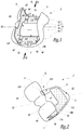
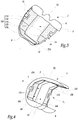
- la
figure 1 est une vue en perspective d'un composant fémoral conforme à l'invention, - les
figures 2 à 4 sont des vues en perspective analogues à lafigure 1 , selon d'autres angles et - la
figure 5 et une vue de dessus du composant desfigures 1 à 4 . - Le composant prothétique fémoral 2 visible aux
figures 1 à 5 est réalisé en alliage métallique, par exemple en alliage à base de Chrome-Cobalt ou Titane ou en céramique, par exemple à base de céramique d'alumine. - Dans ce qui suit, le composant est décrit dans une position montée lorsque le patient se tient debout. Ainsi, une partie inférieure ou distale du composant est orientée vers le tibia et une direction avant-arrière ou antéro-postérieure est perpendiculaire à l'axe de l'articulation du genou et sensiblement horizontale.
- Ce composant comprend une portion externe convexe 4 qui définit deux condyles 42 et 44 prévus pour venir en appui sur un insert en polyéthylène fixé sur un composant tibial d'une prothèse de genou.
- On note X2 un axe longitudinal du composant 2 qui s'étend selon une direction antéro-postérieure, entre une cloison avant 5 et une cloison arrière 6. La surface externe 45, respectivement 46, d'une cloison 5 ou 6 constitue une surface avant ou antérieure, respectivement arrière ou postérieure, de la portion externe 4.
- Le composant 2 défini un volume V2 de réception de l'extrémité inférieure ou distale du fémur d'un patient, après résection de cette extrémité. Ce volume est délimité à l'avant par la cloison 5, à l'arrière par la cloison 6 et vers le bas par un fond 7 qui est globalement parallèle à l'axe X2 et relie les cloisons 5 et 6.
- Ainsi, en vu de côté, le composant 2 présente une forme générale en U à fond interne plat.
- Le composant 2 comprend également une cage intercondylienne 8 qui est destiné à s'insérer dans le fémur du patient, entre les condyles naturels. Cette cage 8 s'étend globalement selon l'axe X2, en surélévation par rapport au fond 7. Elle a, en section dans un plan perpendiculaire à l'axe X2, une forme globalement rectangulaire à coins tronqués.
- On considère les surfaces de la cage intercondylienne 8 orientées vers le volume V2 comme des surfaces internes de cette cage. Cette cage comprend donc une surface interne supérieure 82 parallèle aux surfaces internes du fond 7 et deux surfaces internes latérales gauche 84 et droite 86. Des chanfreins relient les surfaces 82 et 84, d'une part, 82 et 86, d'autre part.
- On note respectivement 74 et 76 les surfaces internes supérieures du fond 7 qui sont disposées à gauche et à droite de la cage 8. Ces surfaces sont parallèles à la surface 82.
- On note 52 la surface interne de la cloison 5, c'est-à-dire la surface de cette cloison tournée vers la cloison 6. On note 62 la surface interne de la cloison 6, c'est-à-dire la surface de cette cloison tournée vers la cloison 5.
- Les surfaces 52, 62, 74 et 76 sont planes. La surface 62 est perpendiculaire à l'axe X2. Les surfaces 52 et 62 divergent ou s'éloignent du fond 7, avec un angle de divergence égal à 5,5°. En pratique, cet angle est compris entre 1 et 10°, de préférence entre 5 et 6°. Le caractère quasi parallèle et divergeant des surfaces 52 et 62 assure un effet de « mise en pression » de l'extrémité réséquée du fémur lors de la pose du composant 2.
- On note 54 une surface interne de la cloison 5 qui est plane et relie les surfaces 74 et 52. On note 56 une surface interne de la cloison 5 qui est plane et relie les surfaces 76 et 52. De la même façon, on note 64 et 66 des surfaces internes de la cloison 6 qui relient les surfaces 74 et 76 à la surface 62. Les surfaces 54, 56, 64 et 66 sont inclinées à environ 45° par rapport à l'axe X2.
- Conformément à l'invention, une couche 100 d'un matériau favorisant la repousse osseuse est déposée sur les surfaces 52, 54, 56, 62, 64, 66, 74 et 76 sans recouvrir les surfaces 82, 84 et 86.
- En d'autres termes, le revêtement favorisant la repousse osseuse est déposé sur des surfaces internes du composant 2 qui sont accessibles par les côtés gauche et droit du composant, dans le sens des flèches F1 et F2 à la
figure 1 , c'est-à-dire perpendiculairement à l'axe X2, lorsque le composant 2 est immobilisé sur l'extrémité reséquée du fémur d'un patient. - Le produit utilisé comme revêtement favorisant la repousse osseuse peut être un plasma spray Titane revêtu ou non d'Hydroxyapatite, un revêtement obtenu par frittage de poudre, de billes ou de fibres.
- La couche 100 de matériau favorisant la repousse osseuse comprend deux bandes latérales 174 et 176 respectivement apposées sur les surfaces 74 et 76 et qui s'étendent de part et d'autre de la cage intercondylienne 8 parallèlement à l'axe X2, c'est-à-dire selon une direction avant/arrière.
- La couche 100 comprend également deux bandes 164 et 166 apposées sur les surfaces 64 et 66 ainsi qu'une bande 162 apposée sur la surface 62. Les bandes 162, 164 et 166 constituent ensemble une portion de la couche 100 qui relie les bandes 174 et 176.
- Par ailleurs, une bande 154 de la couche 100 est apposée sur la surface 54, alors qu'une autre bande 156 de la couche 100 est apposée sur la surface 56. Enfin, une bande 152 de la couche 100 est apposée sur la surface 52. La bande 156 relie ensemble les bandes 176 et 152. Ainsi, les bandes 156 et 152 constituent ensemble une portion de la couche 100 qui prolonge la bande 176 en direction de la bande 174, sur l'intérieur de la cloison avant 5.
- On relève que les bandes 152 et 154 ne sont pas jointives, de sorte qu'il demeure une partie 52A de la surface 52 qui n'est pas revêtue de la couche 100. En variante, les bandes 152 et 154 pourraient être jointives et la surface 52 serait alors presque complètement revêtue de la couche 100. La couche 100 serait alors en forme de boucle fermée entourant la cage 8
- La couche 100, qui est constituée des bandes 152, 154, 156, 162, 164, 166, 174 et 176 est d'un seul tenant. Elle est gauche puisqu'elle s'étend sur des surfaces internes du composant 2 qui sont contigües sans être coplanaires.
- Lors de la pose du composant 2, après résection de l'extrémité inférieure du fémur, le composant est mis en place en engageant la cage intercondylienne 8 dans le dégagement ménagé à cet effet dans le fémur, les condyles 42 et 44 venant approximativement à la place des condyles naturels.
- S'il s'avère ultérieurement nécessaire de retirer le composant 2, il est possible d'agir avec un ostéotome ou tout autre outil coupant dans le sens des flèches F1 et F2 sur la
figure 1 , pour sectionner l'os qui a repoussé, en coupant les ponts osseux entre la prothèse et l'os, en faisant longer à l'ostéotome ou à l'outil coupant les surfaces 52, 54, 56, 62, 64, 66, 74 et 76. - Il n'est pas nécessaire d'utiliser l'ostéotome au niveau des surfaces 82, 84 et 86 puisque celles-ci ne sont pas revêtues de la couche 100, de sorte que la repousse osseuse au niveau de ses surfaces est peu marquée.
- Selon une variante non représentée de l'invention, on peut prévoir d'apposer sur les surfaces 82, 84 et 86 un revêtement empêchant la repousse osseuse, ou plus précisément un revêtement empêchant l'accrochage de l'os sur ses surfaces. En variante, l'état de surface de ses surfaces 82, 84 et 86 peut être d'un type qui ne facilite pas cet accrochage, par exemple de type « poli miroir ».
Claims (10)
- Composant fémoral (2) de prothèse de genou comprenant une portion externe convexe (4) et une cage intercondylienne (8) qui comprend une surface interne supérieure (82) parallèle aux surfaces internes du fond du composant et deux surfaces internes latérales (84), ledit composant ayant une forme générale en U à fond interne plat et étant revêtu, sur au moins une surface interne (52, 54, 56, 62, 64, 66, 74, 76) destinée à être en appui contre une partie reséquée d'un fémur, d'une couche (100) de revêtement favorisant la repousse osseuse, caractérisé en ce que la surface interne supérieure (82) est fermée et en ce que la couche (100) de revêtement est apposée exclusivement sur des surfaces internes (52, 54, 56, 62, 64, 66, 74, 76) du composant (2) qui ne font pas partie de la cage intercondylienne (8).
- Composant selon la revendication 1, caractérisé en ce que la couche (100) de revêtement s'étend continûment sur au moins deux surfaces planes internes (52, 54, 56, 62, 64, 66, 74, 76) contigües du composant qui ne sont pas coplanaires.
- Composant selon la revendication 2, caractérisé en ce que la couche (100) de revêtement est d'un seul tenant.
- Composant selon l'une des revendications précédentes, caractérisé en ce que la couche (100) de revêtement comprend deux bandes latérales (174, 176) disposées de part et d'autre de la cage intercondylienne (8) et qui s'étendent selon une direction antero-postérieure du composant.
- Composant selon la revendication 4, caractérisé en ce que la couche (100) de revêtement comprend au moins une portion (162, 164, 166) de jonction entre les bandes latérales (174, 176).
- Composant selon la revendication 5, caractérisé en ce que la portion de jonction (162, 164, 166) s'étend sur une partie postérieure (6) du composant, en arrière de la cage intercondylienne (8).
- Composant selon l'une des revendications 4 à 6, caractérisé en ce que la couche (100) de revêtement comprend un portion (152, 156) qui prolonge une première bande latérale (176) en direction de la deuxième bande latérale (174), en contournant la cage intercondylienne (8) et en rejoignant ou non la deuxième bande latérale.
- Composant selon les revendications 4 et 7, caractérisé en ce que la portion (152, 156) qui prolonge la première bande latérale (176) s'étend, par rapport à la cage intercondylienne (8), à l'opposé de la portion de jonction (162, 164, 166).
- Méthode de fabrication d'un composant fémoral (2) de prothèse de genou, ce composant ayant une forme générale en U à fond interne plat et comprenant une portion convexe (4) et une cage intercondylienne (8) comprenant une surface interne supérieure (82) fermée, ladite méthode comprenant au moins une étape consistant à appliquer, sur au moins une surface interne (52, 54, 56, 62, 64, 66, 74, 76) parallèle aux surfaces internes du fond du composant destinée à être en appui contre une partie reséquée d'un fémur et à l'exclusion d'une surface interne (82, 84, 86) de la cage intercondylienne (8), une couche (100) de revêtement favorisant la repousse osseuse.
- Prothèse de genou comprenant un composant fémoral (2) selon l'une des revendications 1 à 8 ou fabriqué avec la méthode de la revendication 9.
Applications Claiming Priority (1)
| Application Number | Priority Date | Filing Date | Title |
|---|---|---|---|
| FR1255377A FR2991573A1 (fr) | 2012-06-08 | 2012-06-08 | Composant femoral de prothese de genou, methode de fabrication d'un tel composant et prothese comprenant un tel composant |
Publications (2)
| Publication Number | Publication Date |
|---|---|
| EP2671543A1 EP2671543A1 (fr) | 2013-12-11 |
| EP2671543B1 true EP2671543B1 (fr) | 2020-08-05 |
Family
ID=48537905
Family Applications (1)
| Application Number | Title | Priority Date | Filing Date |
|---|---|---|---|
| EP13171046.9A Not-in-force EP2671543B1 (fr) | 2012-06-08 | 2013-06-07 | Composant fémoral de prothèse de genou, méthode de fabrication d'un tel composant et prothèse comprenant un tel composant |
Country Status (2)
| Country | Link |
|---|---|
| EP (1) | EP2671543B1 (fr) |
| FR (1) | FR2991573A1 (fr) |
Citations (1)
| Publication number | Priority date | Publication date | Assignee | Title |
|---|---|---|---|---|
| US20110230973A1 (en) * | 2007-10-10 | 2011-09-22 | Zimmer, Inc. | Method for bonding a tantalum structure to a cobalt-alloy substrate |
Family Cites Families (6)
| Publication number | Priority date | Publication date | Assignee | Title |
|---|---|---|---|---|
| US6261322B1 (en) * | 1998-05-14 | 2001-07-17 | Hayes Medical, Inc. | Implant with composite coating |
| ES2278716T3 (es) * | 2001-03-26 | 2007-08-16 | Zimmer Gmbh | Protesis de rodilla. |
| US8070821B2 (en) * | 2005-12-27 | 2011-12-06 | Howmedica Osteonics Corp. | Hybrid femoral implant |
| FR2934770B1 (fr) | 2008-08-07 | 2013-03-08 | Fournitures Hospitalieres Ind | Composant femoral prothetique pour prothese de genou a fixation biologique. |
| US8496666B2 (en) * | 2009-08-11 | 2013-07-30 | Imds Corporation | Instrumentation for mobile bearing prosthetics |
| US8287601B2 (en) * | 2010-09-30 | 2012-10-16 | Depuy Products, Inc. | Femoral component of a knee prosthesis having an angled cement pocket |
-
2012
- 2012-06-08 FR FR1255377A patent/FR2991573A1/fr active Pending
-
2013
- 2013-06-07 EP EP13171046.9A patent/EP2671543B1/fr not_active Not-in-force
Patent Citations (1)
| Publication number | Priority date | Publication date | Assignee | Title |
|---|---|---|---|---|
| US20110230973A1 (en) * | 2007-10-10 | 2011-09-22 | Zimmer, Inc. | Method for bonding a tantalum structure to a cobalt-alloy substrate |
Also Published As
| Publication number | Publication date |
|---|---|
| EP2671543A1 (fr) | 2013-12-11 |
| FR2991573A1 (fr) | 2013-12-13 |
Similar Documents
| Publication | Publication Date | Title |
|---|---|---|
| EP3449876B1 (fr) | Prothèse de cheville améliorée | |
| EP3687455B1 (fr) | Prothèse de cheville comportant un implant talien, un implant tibial et un insert, et kit incluant au moins une telle prothèse | |
| EP1510190B1 (fr) | Composant glénoidien de prothèse d'épaule et prothèse totale d'épaule incorporant un tel composant | |
| EP1025819B1 (fr) | Prothese totale du genou à insert mobile par rapport à un tenon | |
| EP2547291B1 (fr) | Prothese du genou avec plaque meniscale mixte | |
| FR2896404A1 (fr) | Ensemble d'instrumentation chirurgicale pour poser une prothese de cheville | |
| FR2926719A1 (fr) | Ensemble compose d'une embase tibiale et d'un insert tibial et prothese comprenant un tel ensemble | |
| EP1308142A2 (fr) | Implant rotulien et prothèse de genou incorporant un tel implant | |
| FR2854792A1 (fr) | Jeu d'elements prothetiques pour un ensemble prothetique tibial | |
| FR2634373A1 (fr) | Prothese totale du genou | |
| FR2905590A1 (fr) | Plaque d'arthrodese d'une articulation metatarso- phalangienne. | |
| EP2676637B1 (fr) | Ensemble d'implants fémoraux pour une prothèse du genou | |
| FR2780636A1 (fr) | Prothese de genou modulable | |
| FR3065368A1 (fr) | Implant d'arthrodese et kit chirurgical comprenant un tel implant | |
| FR3019032A1 (fr) | Implant femoral comportant une portion de reception avec des picots d’ancrage et prothese totale de genou comprenant un tel implant femoral | |
| EP2671543A1 (fr) | Composant fémoral de prothèse de genou, méthode de fabrication d'un tel composant et prothèse comprenant un tel composant | |
| FR2684291A1 (fr) | Prothese de cheville. | |
| FR2630639A1 (fr) | Dispositif de prothese partielle du genou | |
| FR2844994A1 (fr) | Implant femoral anatomique pour prothese de hanche | |
| EP3498231B1 (fr) | Gamme d'implants fémoraux et prothèse totale de genou comprenant un implant fémoral sélectionné dans une telle gamme d'implants fémoraux | |
| FR3055538A1 (fr) | Implant tibial autobloquant | |
| WO2021089932A1 (fr) | Coque d'habillage de prothèse de membre inférieur | |
| EP1728490A1 (fr) | Pièce prothétique constitutive d'une prothèse de remplacement d'une articulation entre deux os d'un étre humain ou analogue | |
| EP1693026A1 (fr) | Implant tibial et prothèse de genou unicondylienne le comportant | |
| EP2491893B1 (fr) | Implant de reprise fémorale et ancillaire de mise en oeuvre chirurgicale |
Legal Events
| Date | Code | Title | Description |
|---|---|---|---|
| PUAI | Public reference made under article 153(3) epc to a published international application that has entered the european phase |
Free format text: ORIGINAL CODE: 0009012 |
|
| AK | Designated contracting states |
Kind code of ref document: A1 Designated state(s): AL AT BE BG CH CY CZ DE DK EE ES FI FR GB GR HR HU IE IS IT LI LT LU LV MC MK MT NL NO PL PT RO RS SE SI SK SM TR |
|
| AX | Request for extension of the european patent |
Extension state: BA ME |
|
| RIN1 | Information on inventor provided before grant (corrected) |
Inventor name: VIEIRA DA SILVA, MANUEL Inventor name: COURAGE, OLIVIER Inventor name: GOUBET, NICOLAS Inventor name: FAURE, ERIC Inventor name: LEONARDI, FRANCESCO Inventor name: FORTI, MAURIZIO Inventor name: DARMAN, ZULGAEL |
|
| 17P | Request for examination filed |
Effective date: 20140602 |
|
| RBV | Designated contracting states (corrected) |
Designated state(s): AL AT BE BG CH CY CZ DE DK EE ES FI FR GB GR HR HU IE IS IT LI LT LU LV MC MK MT NL NO PL PT RO RS SE SI SK SM TR |
|
| 17Q | First examination report despatched |
Effective date: 20160404 |
|
| RAP1 | Party data changed (applicant data changed or rights of an application transferred) |
Owner name: CORIN LIMITED |
|
| STAA | Information on the status of an ep patent application or granted ep patent |
Free format text: STATUS: EXAMINATION IS IN PROGRESS |
|
| RIC1 | Information provided on ipc code assigned before grant |
Ipc: A61F 2/38 20060101AFI20191218BHEP Ipc: A61F 2/30 20060101ALN20191218BHEP |
|
| GRAP | Despatch of communication of intention to grant a patent |
Free format text: ORIGINAL CODE: EPIDOSNIGR1 |
|
| STAA | Information on the status of an ep patent application or granted ep patent |
Free format text: STATUS: GRANT OF PATENT IS INTENDED |
|
| INTG | Intention to grant announced |
Effective date: 20200129 |
|
| GRAS | Grant fee paid |
Free format text: ORIGINAL CODE: EPIDOSNIGR3 |
|
| GRAA | (expected) grant |
Free format text: ORIGINAL CODE: 0009210 |
|
| STAA | Information on the status of an ep patent application or granted ep patent |
Free format text: STATUS: THE PATENT HAS BEEN GRANTED |
|
| AK | Designated contracting states |
Kind code of ref document: B1 Designated state(s): AL AT BE BG CH CY CZ DE DK EE ES FI FR GB GR HR HU IE IS IT LI LT LU LV MC MK MT NL NO PL PT RO RS SE SI SK SM TR |
|
| REG | Reference to a national code |
Ref country code: GB Ref legal event code: FG4D Free format text: NOT ENGLISH |
|
| REG | Reference to a national code |
Ref country code: CH Ref legal event code: EP |
|
| REG | Reference to a national code |
Ref country code: AT Ref legal event code: REF Ref document number: 1297661 Country of ref document: AT Kind code of ref document: T Effective date: 20200815 |
|
| REG | Reference to a national code |
Ref country code: DE Ref legal event code: R096 Ref document number: 602013071261 Country of ref document: DE |
|
| REG | Reference to a national code |
Ref country code: IE Ref legal event code: FG4D Free format text: LANGUAGE OF EP DOCUMENT: FRENCH |
|
| REG | Reference to a national code |
Ref country code: LT Ref legal event code: MG4D |
|
| REG | Reference to a national code |
Ref country code: NL Ref legal event code: MP Effective date: 20200805 |
|
| REG | Reference to a national code |
Ref country code: AT Ref legal event code: MK05 Ref document number: 1297661 Country of ref document: AT Kind code of ref document: T Effective date: 20200805 |
|
| PG25 | Lapsed in a contracting state [announced via postgrant information from national office to epo] |
Ref country code: LT Free format text: LAPSE BECAUSE OF FAILURE TO SUBMIT A TRANSLATION OF THE DESCRIPTION OR TO PAY THE FEE WITHIN THE PRESCRIBED TIME-LIMIT Effective date: 20200805 Ref country code: HR Free format text: LAPSE BECAUSE OF FAILURE TO SUBMIT A TRANSLATION OF THE DESCRIPTION OR TO PAY THE FEE WITHIN THE PRESCRIBED TIME-LIMIT Effective date: 20200805 Ref country code: SE Free format text: LAPSE BECAUSE OF FAILURE TO SUBMIT A TRANSLATION OF THE DESCRIPTION OR TO PAY THE FEE WITHIN THE PRESCRIBED TIME-LIMIT Effective date: 20200805 Ref country code: NO Free format text: LAPSE BECAUSE OF FAILURE TO SUBMIT A TRANSLATION OF THE DESCRIPTION OR TO PAY THE FEE WITHIN THE PRESCRIBED TIME-LIMIT Effective date: 20201105 Ref country code: AT Free format text: LAPSE BECAUSE OF FAILURE TO SUBMIT A TRANSLATION OF THE DESCRIPTION OR TO PAY THE FEE WITHIN THE PRESCRIBED TIME-LIMIT Effective date: 20200805 Ref country code: FI Free format text: LAPSE BECAUSE OF FAILURE TO SUBMIT A TRANSLATION OF THE DESCRIPTION OR TO PAY THE FEE WITHIN THE PRESCRIBED TIME-LIMIT Effective date: 20200805 Ref country code: GR Free format text: LAPSE BECAUSE OF FAILURE TO SUBMIT A TRANSLATION OF THE DESCRIPTION OR TO PAY THE FEE WITHIN THE PRESCRIBED TIME-LIMIT Effective date: 20201106 Ref country code: PT Free format text: LAPSE BECAUSE OF FAILURE TO SUBMIT A TRANSLATION OF THE DESCRIPTION OR TO PAY THE FEE WITHIN THE PRESCRIBED TIME-LIMIT Effective date: 20201207 Ref country code: BG Free format text: LAPSE BECAUSE OF FAILURE TO SUBMIT A TRANSLATION OF THE DESCRIPTION OR TO PAY THE FEE WITHIN THE PRESCRIBED TIME-LIMIT Effective date: 20201105 Ref country code: ES Free format text: LAPSE BECAUSE OF FAILURE TO SUBMIT A TRANSLATION OF THE DESCRIPTION OR TO PAY THE FEE WITHIN THE PRESCRIBED TIME-LIMIT Effective date: 20200805 |
|
| PG25 | Lapsed in a contracting state [announced via postgrant information from national office to epo] |
Ref country code: RS Free format text: LAPSE BECAUSE OF FAILURE TO SUBMIT A TRANSLATION OF THE DESCRIPTION OR TO PAY THE FEE WITHIN THE PRESCRIBED TIME-LIMIT Effective date: 20200805 Ref country code: LV Free format text: LAPSE BECAUSE OF FAILURE TO SUBMIT A TRANSLATION OF THE DESCRIPTION OR TO PAY THE FEE WITHIN THE PRESCRIBED TIME-LIMIT Effective date: 20200805 Ref country code: NL Free format text: LAPSE BECAUSE OF FAILURE TO SUBMIT A TRANSLATION OF THE DESCRIPTION OR TO PAY THE FEE WITHIN THE PRESCRIBED TIME-LIMIT Effective date: 20200805 Ref country code: PL Free format text: LAPSE BECAUSE OF FAILURE TO SUBMIT A TRANSLATION OF THE DESCRIPTION OR TO PAY THE FEE WITHIN THE PRESCRIBED TIME-LIMIT Effective date: 20200805 Ref country code: IS Free format text: LAPSE BECAUSE OF FAILURE TO SUBMIT A TRANSLATION OF THE DESCRIPTION OR TO PAY THE FEE WITHIN THE PRESCRIBED TIME-LIMIT Effective date: 20201205 |
|
| PG25 | Lapsed in a contracting state [announced via postgrant information from national office to epo] |
Ref country code: SM Free format text: LAPSE BECAUSE OF FAILURE TO SUBMIT A TRANSLATION OF THE DESCRIPTION OR TO PAY THE FEE WITHIN THE PRESCRIBED TIME-LIMIT Effective date: 20200805 Ref country code: RO Free format text: LAPSE BECAUSE OF FAILURE TO SUBMIT A TRANSLATION OF THE DESCRIPTION OR TO PAY THE FEE WITHIN THE PRESCRIBED TIME-LIMIT Effective date: 20200805 Ref country code: DK Free format text: LAPSE BECAUSE OF FAILURE TO SUBMIT A TRANSLATION OF THE DESCRIPTION OR TO PAY THE FEE WITHIN THE PRESCRIBED TIME-LIMIT Effective date: 20200805 Ref country code: CZ Free format text: LAPSE BECAUSE OF FAILURE TO SUBMIT A TRANSLATION OF THE DESCRIPTION OR TO PAY THE FEE WITHIN THE PRESCRIBED TIME-LIMIT Effective date: 20200805 Ref country code: EE Free format text: LAPSE BECAUSE OF FAILURE TO SUBMIT A TRANSLATION OF THE DESCRIPTION OR TO PAY THE FEE WITHIN THE PRESCRIBED TIME-LIMIT Effective date: 20200805 |
|
| REG | Reference to a national code |
Ref country code: DE Ref legal event code: R097 Ref document number: 602013071261 Country of ref document: DE |
|
| PG25 | Lapsed in a contracting state [announced via postgrant information from national office to epo] |
Ref country code: AL Free format text: LAPSE BECAUSE OF FAILURE TO SUBMIT A TRANSLATION OF THE DESCRIPTION OR TO PAY THE FEE WITHIN THE PRESCRIBED TIME-LIMIT Effective date: 20200805 |
|
| PLBE | No opposition filed within time limit |
Free format text: ORIGINAL CODE: 0009261 |
|
| STAA | Information on the status of an ep patent application or granted ep patent |
Free format text: STATUS: NO OPPOSITION FILED WITHIN TIME LIMIT |
|
| PG25 | Lapsed in a contracting state [announced via postgrant information from national office to epo] |
Ref country code: SK Free format text: LAPSE BECAUSE OF FAILURE TO SUBMIT A TRANSLATION OF THE DESCRIPTION OR TO PAY THE FEE WITHIN THE PRESCRIBED TIME-LIMIT Effective date: 20200805 |
|
| 26N | No opposition filed |
Effective date: 20210507 |
|
| PG25 | Lapsed in a contracting state [announced via postgrant information from national office to epo] |
Ref country code: IT Free format text: LAPSE BECAUSE OF FAILURE TO SUBMIT A TRANSLATION OF THE DESCRIPTION OR TO PAY THE FEE WITHIN THE PRESCRIBED TIME-LIMIT Effective date: 20200805 |
|
| PG25 | Lapsed in a contracting state [announced via postgrant information from national office to epo] |
Ref country code: SI Free format text: LAPSE BECAUSE OF FAILURE TO SUBMIT A TRANSLATION OF THE DESCRIPTION OR TO PAY THE FEE WITHIN THE PRESCRIBED TIME-LIMIT Effective date: 20200805 |
|
| REG | Reference to a national code |
Ref country code: DE Ref legal event code: R119 Ref document number: 602013071261 Country of ref document: DE |
|
| PG25 | Lapsed in a contracting state [announced via postgrant information from national office to epo] |
Ref country code: MC Free format text: LAPSE BECAUSE OF FAILURE TO SUBMIT A TRANSLATION OF THE DESCRIPTION OR TO PAY THE FEE WITHIN THE PRESCRIBED TIME-LIMIT Effective date: 20200805 |
|
| REG | Reference to a national code |
Ref country code: CH Ref legal event code: PL |
|
| GBPC | Gb: european patent ceased through non-payment of renewal fee |
Effective date: 20210607 |
|
| REG | Reference to a national code |
Ref country code: BE Ref legal event code: MM Effective date: 20210630 |
|
| PG25 | Lapsed in a contracting state [announced via postgrant information from national office to epo] |
Ref country code: LU Free format text: LAPSE BECAUSE OF NON-PAYMENT OF DUE FEES Effective date: 20210607 |
|
| PG25 | Lapsed in a contracting state [announced via postgrant information from national office to epo] |
Ref country code: LI Free format text: LAPSE BECAUSE OF NON-PAYMENT OF DUE FEES Effective date: 20210630 Ref country code: IE Free format text: LAPSE BECAUSE OF NON-PAYMENT OF DUE FEES Effective date: 20210607 Ref country code: GB Free format text: LAPSE BECAUSE OF NON-PAYMENT OF DUE FEES Effective date: 20210607 Ref country code: DE Free format text: LAPSE BECAUSE OF NON-PAYMENT OF DUE FEES Effective date: 20220101 Ref country code: CH Free format text: LAPSE BECAUSE OF NON-PAYMENT OF DUE FEES Effective date: 20210630 |
|
| PG25 | Lapsed in a contracting state [announced via postgrant information from national office to epo] |
Ref country code: FR Free format text: LAPSE BECAUSE OF NON-PAYMENT OF DUE FEES Effective date: 20210630 |
|
| PG25 | Lapsed in a contracting state [announced via postgrant information from national office to epo] |
Ref country code: BE Free format text: LAPSE BECAUSE OF NON-PAYMENT OF DUE FEES Effective date: 20210630 |
|
| PG25 | Lapsed in a contracting state [announced via postgrant information from national office to epo] |
Ref country code: HU Free format text: LAPSE BECAUSE OF FAILURE TO SUBMIT A TRANSLATION OF THE DESCRIPTION OR TO PAY THE FEE WITHIN THE PRESCRIBED TIME-LIMIT; INVALID AB INITIO Effective date: 20130607 |
|
| PG25 | Lapsed in a contracting state [announced via postgrant information from national office to epo] |
Ref country code: CY Free format text: LAPSE BECAUSE OF FAILURE TO SUBMIT A TRANSLATION OF THE DESCRIPTION OR TO PAY THE FEE WITHIN THE PRESCRIBED TIME-LIMIT Effective date: 20200805 |
|
| PG25 | Lapsed in a contracting state [announced via postgrant information from national office to epo] |
Ref country code: MK Free format text: LAPSE BECAUSE OF FAILURE TO SUBMIT A TRANSLATION OF THE DESCRIPTION OR TO PAY THE FEE WITHIN THE PRESCRIBED TIME-LIMIT Effective date: 20200805 |
|
| PG25 | Lapsed in a contracting state [announced via postgrant information from national office to epo] |
Ref country code: MT Free format text: LAPSE BECAUSE OF FAILURE TO SUBMIT A TRANSLATION OF THE DESCRIPTION OR TO PAY THE FEE WITHIN THE PRESCRIBED TIME-LIMIT Effective date: 20200805 |
|
| PG25 | Lapsed in a contracting state [announced via postgrant information from national office to epo] |
Ref country code: TR Free format text: LAPSE BECAUSE OF FAILURE TO SUBMIT A TRANSLATION OF THE DESCRIPTION OR TO PAY THE FEE WITHIN THE PRESCRIBED TIME-LIMIT Effective date: 20200805 |