EP2671491B1 - Urine Stowage System for Spacecraft - Google Patents
Urine Stowage System for Spacecraft Download PDFInfo
- Publication number
- EP2671491B1 EP2671491B1 EP13170010.6A EP13170010A EP2671491B1 EP 2671491 B1 EP2671491 B1 EP 2671491B1 EP 13170010 A EP13170010 A EP 13170010A EP 2671491 B1 EP2671491 B1 EP 2671491B1
- Authority
- EP
- European Patent Office
- Prior art keywords
- bag
- urine
- urinal
- pressure
- urine storage
- Prior art date
- Legal status (The legal status is an assumption and is not a legal conclusion. Google has not performed a legal analysis and makes no representation as to the accuracy of the status listed.)
- Active
Links
Images
Classifications
-
- B—PERFORMING OPERATIONS; TRANSPORTING
- B64—AIRCRAFT; AVIATION; COSMONAUTICS
- B64G—COSMONAUTICS; VEHICLES OR EQUIPMENT THEREFOR
- B64G1/00—Cosmonautic vehicles
- B64G1/22—Parts of, or equipment specially adapted for fitting in or to, cosmonautic vehicles
- B64G1/60—Crew or passenger accommodations
-
- E—FIXED CONSTRUCTIONS
- E03—WATER SUPPLY; SEWERAGE
- E03D—WATER-CLOSETS OR URINALS WITH FLUSHING DEVICES; FLUSHING VALVES THEREFOR
- E03D13/00—Urinals ; Means for connecting the urinal to the flushing pipe and the wastepipe; Splashing shields for urinals
- E03D13/007—Waterless or low-flush urinals; Accessories therefor
Definitions
- This disclosure relates to a waste handling system, such as a urine stowage system for a spacecraft.
- the first solution is to vent the urine overboard, which has been employed on the Shuttle Orbiter and other prior United States spaceships.
- the second solution is to stow the urine on board, which has been employed in the Soviet/Russian Soyuz spaceship and the International Space Station. Stowing urine on board has become the desired approach for new spacecraft.
- urine is absorbed by a product placed inside of a canister.
- the canister is emptied after return to Earth, limiting urine stowage to the volume of the canister.
- the urine is pumped directly to a urine processor, where urine is processed and plumbed to the water processor for further processing to produce potable water.
- US-A-6258215 discloses a waste handling system having the features of the preamble of claim 1.
- the invention provides a waste handling system as set forth in claim 1.
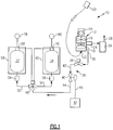
- a waste handling system 10 is schematically illustrated in Figure 1 .
- the system 10 includes a waste processing unit 12 having a motor 14 that rotationally drives a fan 16 and a pumping element, such as a urine separator 18.
- a urinal 20 is fluidly connected to a urinal inlet 22 of the unit 12.
- the separator 18 receives urine from the urinal 20, which is a mixture of urine and air.
- the separator 18 separates the urine and air from one another.
- the air is expelled from the unit 12 through an air outlet 24 that provides the air to a filter 26.
- the filter 26 neutralizes odor and bacteria and vents the filtered air through a vent 28, which may be provided back to a cabin, for example.
- the separated urine is expelled through a urine outlet 30 of the unit 12.
- the urine is provided to first and second urine bags 32, 34 through a distribution system 36.
- the distribution system 36 includes a shut-off valve 38 that can be moved mechanically or electrically between opened and closed positions to selectively connect the unit 12 to the first and second urine bags 32, 34, for example, to service or replace the unit 12.
- a differential pressure valve 40 is provided downstream from the shut-off valve 38.
- the differential pressure valve 40 is fluidly connected to an upstream separator line 42 and a downstream main bag line 44.
- the differential pressure valve 40 is configured to automatically open in response to a selected differential pressure provided, in part, by pressurized urine provided from the separator line 42.
- the differential pressure is about 20 psi (137.9 kPa).
- the differential pressure valve 40 uses a reference pressure that may remain generally constant.
- the differential pressure valve may be in fluid communication with a cabin 47 and its associated cabin pressure through a cabin line 46. Such a configuration ensures that the differential pressure across the differential pressure valve 40 will not vary based upon the pressure within the first and second urine bags 32, 34. It should be understood that a reference pressure other than cabin pressure may be used.
- the main bag line 44 is in fluid communication with a flow diverter valve 48, which is fluidly connected to first and second bag lines 50, 52 on a downstream side of the flow diverter valve 48.
- the first and second bag lines 50, 52 are respectively fluidly connected to the first and second urine bags 32, 34.
- First and second quick disconnects 54, 56 may be provided between the first and second bag lines 50, 52 and the first and second urine bags 32, 34, respectively, to facilitate a quick and easy change of a full urine bag with a new, empty urine bag.
- the first and second urine bags 32, 34 are flexible containers that expand as urine fills the bags.
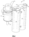
- Each of the first and second urine bags 32, 34 are respectively housed within rigid first and second containers 58, 60, which are shown in more detail in Figure 2 .
- the containers are provided by cylindrical bodies, although it may be desirable to include a taper such that the base diameter is less than the open end diameter where the bag is intended to be removed. This would allow the bags to be removed more easily from the first and second containers 58, 60.
- Each of the first and second containers 58, 60 includes a lid 64 pivotally attached to the container housing by a hinge 66, as shown in Figure 2 .
- a double latch 62 may be used to maintain the lid 64 in a closed condition.
- Initial release of the latch 62 permits the lid 64 to open a fixed distance relative to the container body, which ensures that the urine bag does not unexpectedly rupture under pressure with the lid fully open, or release more energy than the operator should be exposed to.
- the latch 62 may then be fully released to fully open the lid 64 and permit removal of the bag.
- An alternate safety mechanism may be included to expand the internal volume prior to opening the access door, for example, a cam that the operator actuates to move an internal pressure plate.
- the flow diverter valve 48 automatically switches between the first and second urine bags 32, 34 in response to an input, which may be based upon the condition of the urine bag within its respective container.
- the input may be provided by a command signal from a switching system.
- the flow diverter valve 48 is commanded to automatically block flow to the filled bag and to permit flow to the other urine bag, which is empty, enabling the full urine bag to be changed.
- the first and second containers 58, 60 respectively include first and second switches 68, 70 in communication with the flow diverter valve 48. Each switch communicates with its respective bag and provides the command signal when the bag is full.
- the switching system may also include first and second indicators 78, 80, such as lights, which provides a visual indication when the bag is full. Other non-electrical visual indicators maybe used to simplify the system, a color coded wheel may turn as the bag reaches capacity, for instance.
- the bag changes volume within the storage container as the bag transitions from empty to full.
- the switch 68 includes first and second contacts 72, 74 that are spaced apart from one another when the urine bag is not full.
- a biasing member 76 maintains separation between the first and second contacts 72, 74.
- the second contact 74 is moved into engagement with the first contact 72, closing the circuit between a power source 82 and the first indicator 78.
- the closed circuit may also provide the command signal to the flow diverter valve, as described above.
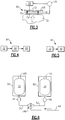
- the "bagged” urine may be recycled according to the system 84 schematically illustrated in Figure 4 .
- the urine which accounts for three quarters of consumed potable water, will replace the volume that was filled with potable water during launch.
- the bag 32 from one spacecraft may be brought to a remote water processing unit 84, for example, at the International Space Station, to produce potable water 88. This can add to the station's water production and lighten the transport spaceship prior to re-entry.
- the urine may be pumped from the separator directly to a tank that may be part of this system, or reside elsewhere in the ship.
- the urine may be pumped from the urine separator directly to a single bag. The operator would be alerted, using the methods described above, when the bag has reached its predetermined or selected volume limit.
- the volume limit would, for example, include adequate empty volume to accommodate the last user.
- the bag 32 may be stowed in a system 92 shown in Figure 5 .
- the full bag 32 is placed in a storage container 90.
- the storage container 90 is capable of protecting the bag 32 from vacuum environment.
- the first and second containers 58, 60 house first and second bags 32, 34.
- the main bag line 44 provides urine to the first and second bags 32, 34 through a mechanical flow diverter valve 148 that selectively supplies urine to the first and second bags 32, 34 via first and second bag lines 50, 52 and first and second quick connects 54, 56.
- Each of the first and second containers 58, 60 include a mechanical device 168, 170 that is configured to provide a visual indicator of the bag being full when the first and second bags 32, 34 become full at a second volume.
- the full bag cooperates with the mechanical device to provide a colored visual indication that the bag is full by positioning a color indicator in a window on the lid, for example.
- a member of the crew upon seeing the visual indication of the bag being full may manually actuate the flow diverter valve 142 to switch the flow or urine from the main bag line 44 to the other bag.
Landscapes
- Engineering & Computer Science (AREA)
- Remote Sensing (AREA)
- Aviation & Aerospace Engineering (AREA)
- Health & Medical Sciences (AREA)
- Public Health (AREA)
- Life Sciences & Earth Sciences (AREA)
- Hydrology & Water Resources (AREA)
- Water Supply & Treatment (AREA)
- Non-Flushing Toilets (AREA)
- Vehicle Waterproofing, Decoration, And Sanitation Devices (AREA)
Description
- This disclosure relates to a waste handling system, such as a urine stowage system for a spacecraft.
- Excluding diapers, there are currently two solutions regarding urine management in orbit. The first solution is to vent the urine overboard, which has been employed on the Shuttle Orbiter and other prior United States spaceships. The second solution is to stow the urine on board, which has been employed in the Soviet/Russian Soyuz spaceship and the International Space Station. Stowing urine on board has become the desired approach for new spacecraft.
- On the Soyuz spaceship, urine is absorbed by a product placed inside of a canister. The canister is emptied after return to Earth, limiting urine stowage to the volume of the canister. In the International Space Station, the urine is pumped directly to a urine processor, where urine is processed and plumbed to the water processor for further processing to produce potable water.
-
US-A-6258215 discloses a waste handling system having the features of the preamble of claim 1. - The invention provides a waste handling system as set forth in claim 1.
- Features of embodiments of the invention are set forth in the dependent claims.
- The disclosure can be further understood by reference to the following detailed description when considered in connection with the accompanying drawings wherein:
-
Figure 1 is a highly schematic view of a waste handling system. -
Figure 2 is a schematic perspective view of a waste processing unit and urine storage containers. -
Figure 3 is a schematic view of an example switch configured to indicate when a urine bag is full. -
Figure 4 is a schematic view of a urine stowage system in which a urine container is further processed to provide potable water. -
Figure 5 is a schematic view of a urine stowage system in which the urine container is stored subsequent to replacement. -
Figure 6 is a schematic view of a portion of another example waste handling system. - A
waste handling system 10 is schematically illustrated inFigure 1 . Thesystem 10 includes awaste processing unit 12 having amotor 14 that rotationally drives afan 16 and a pumping element, such as aurine separator 18. A urinal 20 is fluidly connected to aurinal inlet 22 of theunit 12. Theseparator 18 receives urine from the urinal 20, which is a mixture of urine and air. Theseparator 18 separates the urine and air from one another. The air is expelled from theunit 12 through anair outlet 24 that provides the air to afilter 26. Thefilter 26 neutralizes odor and bacteria and vents the filtered air through avent 28, which may be provided back to a cabin, for example. - The separated urine is expelled through a
urine outlet 30 of theunit 12. The urine is provided to first andsecond urine bags distribution system 36. In one example, thedistribution system 36 includes a shut-offvalve 38 that can be moved mechanically or electrically between opened and closed positions to selectively connect theunit 12 to the first andsecond urine bags unit 12. Adifferential pressure valve 40 is provided downstream from the shut-offvalve 38. Thedifferential pressure valve 40 is fluidly connected to anupstream separator line 42 and a downstreammain bag line 44. Thedifferential pressure valve 40 is configured to automatically open in response to a selected differential pressure provided, in part, by pressurized urine provided from theseparator line 42. In one example, the differential pressure is about 20 psi (137.9 kPa). - The
differential pressure valve 40 uses a reference pressure that may remain generally constant. For example, the differential pressure valve may be in fluid communication with acabin 47 and its associated cabin pressure through acabin line 46. Such a configuration ensures that the differential pressure across thedifferential pressure valve 40 will not vary based upon the pressure within the first andsecond urine bags - The
main bag line 44 is in fluid communication with aflow diverter valve 48, which is fluidly connected to first andsecond bag lines flow diverter valve 48. The first andsecond bag lines second urine bags quick disconnects second bag lines second urine bags - In the example, the first and
second urine bags second urine bags second containers Figure 2 . In the example, the containers are provided by cylindrical bodies, although it may be desirable to include a taper such that the base diameter is less than the open end diameter where the bag is intended to be removed. This would allow the bags to be removed more easily from the first andsecond containers second containers lid 64 pivotally attached to the container housing by ahinge 66, as shown inFigure 2 . Adouble latch 62 may be used to maintain thelid 64 in a closed condition. Initial release of thelatch 62 permits thelid 64 to open a fixed distance relative to the container body, which ensures that the urine bag does not unexpectedly rupture under pressure with the lid fully open, or release more energy than the operator should be exposed to. Thelatch 62 may then be fully released to fully open thelid 64 and permit removal of the bag. An alternate safety mechanism may be included to expand the internal volume prior to opening the access door, for example, a cam that the operator actuates to move an internal pressure plate. - In one example, the
flow diverter valve 48 automatically switches between the first andsecond urine bags flow diverter valve 48 is commanded to automatically block flow to the filled bag and to permit flow to the other urine bag, which is empty, enabling the full urine bag to be changed. - The first and
second containers second switches flow diverter valve 48. Each switch communicates with its respective bag and provides the command signal when the bag is full. The switching system may also include first andsecond indicators - One example switch configuration is schematically illustrated in
Figure 3 . The bag changes volume within the storage container as the bag transitions from empty to full. Theswitch 68 includes first andsecond contacts biasing member 76 maintains separation between the first andsecond contacts urine bag 32 fills, thesecond contact 74 is moved into engagement with thefirst contact 72, closing the circuit between apower source 82 and thefirst indicator 78. The closed circuit may also provide the command signal to the flow diverter valve, as described above. - The "bagged" urine may be recycled according to the
system 84 schematically illustrated inFigure 4 . The urine, which accounts for three quarters of consumed potable water, will replace the volume that was filled with potable water during launch. Thebag 32 from one spacecraft may be brought to a remotewater processing unit 84, for example, at the International Space Station, to producepotable water 88. This can add to the station's water production and lighten the transport spaceship prior to re-entry. - As an alternative, the urine may be pumped from the separator directly to a tank that may be part of this system, or reside elsewhere in the ship. As another alternative, the urine may be pumped from the urine separator directly to a single bag. The operator would be alerted, using the methods described above, when the bag has reached its predetermined or selected volume limit. The volume limit would, for example, include adequate empty volume to accommodate the last user.
- The
bag 32 may be stowed in asystem 92 shown inFigure 5 . Thefull bag 32 is placed in astorage container 90. In one example, thestorage container 90 is capable of protecting thebag 32 from vacuum environment. - Another example waste handling system is shown in
Figure 6 for switching between multiple bags. The first andsecond containers second bags main bag line 44 provides urine to the first andsecond bags flow diverter valve 148 that selectively supplies urine to the first andsecond bags second bag lines - Each of the first and
second containers mechanical device second bags main bag line 44 to the other bag. - Although an example embodiment has been disclosed, a worker of ordinary skill in this art would recognize that certain modifications would come within the scope of the claims. For that reason, the following claims should be studied to determine their true scope and content.
Claims (15)
- A waste handling system comprising:a urinal (20);first and second urine storage containers (58, 60); and a distribution system (36) fluidly interconnecting the urinal (20) to the first and second urine storage containers (58, 60), the distribution system (36) including a switching system selectively fluidly connecting the urinal (20) to at least one of the first and second urinal storage containers (58, 60) in response to an input and characterized by further comprising;a waste processing unit (12) including a urinal inlet (22) configured to receive urine, a urinal outlet (30), and a pumping element (18) fluidly connected between the urinal inlet (12) and the urinal outlet (30); anda differential pressure valve (40) selectively fluidly connecting the urinal outlet (30) to the urine storage containers (58, 60), the differential pressure valve (40) including first, second and third pressure inputs, the first pressure input corresponding to a pressure from the urinal outlet (30), the second pressure input corresponding to a pressure from the urine storage container (58, 60), and the third pressure input corresponding to a reference pressure, the differential pressure valve (40) configured to open and close in response to a differential pressure between the first and third pressures.
- The system according to claim 1, wherein the urine storage container (58, 60) includes a cavity having a bag (32, 34), the bag movable within the cavity between first and second volumes.
- The system according to claim 2, wherein the bag (32, 34) includes a quick disconnect (54, 56) removably coupled to the distribution system (36).
- The system according to claim 3, comprising a water processing unit (84) configured to produce potable water, the bag (32, 34) configured to be coupled to the water processing unit (84) by the quick disconnect (54, 56) to generate potable water from the urine.
- The system according to claim 3, comprising a storage container (90) and a new bag (32), the storage container (90) configured to receive a full bag (32) from one of the first and second storage containers, and the new bag (32) configured to replace the full bag (32) and connect to the distribution system at the quick disconnect (54, 56).
- The system according to any of claims 2 to 5 and comprising;
a mechanical device (168, 170) configured to be actuated in response to the bag (32, 34) changing from the first volume to the second volume, the mechanical device (168, 170) providing a visual indicator of the bag being full at the second volume. - The system according to claim 6, comprising a manual flow diverter valve (142) configured to be manually change between first and second positions corresponding respectively to a fluid connection between one urine storage container (58, 60) and the other urine storage container (58, 60).
- The system according to any preceding claim, wherein the switching system includes a flow diverter valve (48), and the input corresponds to a command signal to the flow diverter valve (48), the command signal commanding the flow diverter valve (48) between first and second positions respectively corresponding to a fluid connection between the first and second urine storage containers (58, 60) and the urinal (20) and a fluid disconnect between the other of the first and second urine storage containers (58, 60) and the urinal (20).
- The system according to claim 8, wherein the switching system includes a switch (68, 70) configured to provide the command signal.
- The system according to claim 9, comprising a light (78, 80) electrically connected to the switch, the light configured to illuminate during a full bag condition.
- The system according to any of claims 8 to 10, wherein the flow diverter valve (48) automatically switches between the first and second urine storage bags (32, 34) in response to the command signal.
- The system according to any of claims 8 to 10, wherein a switch (68, 70) is arranged in each of the first and second urine storage containers (58, 60), each switch including first and second contact elements (72, 74) biased apart from one another in a first condition corresponding to a first volume, and electrically engaging one another in a second condition corresponding to the second volume.
- The system according to any preceding claim, wherein the differential pressure valve (40) is configured to automatically open at a selected pressure differential.
- The system according to claim 13, wherein the reference pressure, for example corresponding to a cabin pressure, is generally constant and the second pressure increases as the urine storage container (58, 60) transitions from an empty condition to a full condition.
- The system according to any preceding claim, comprising a shut-off valve (38) fluidly arranged between the urinal outlet (30) and the differential pressure valve (40).
Priority Applications (1)
| Application Number | Priority Date | Filing Date | Title |
|---|---|---|---|
| EP18189696.0A EP3420870B1 (en) | 2012-06-05 | 2013-05-31 | Urine stowage system for spacecraft |
Applications Claiming Priority (1)
| Application Number | Priority Date | Filing Date | Title |
|---|---|---|---|
| US13/488,570 US9352857B2 (en) | 2012-06-05 | 2012-06-05 | Urine stowage system for spacecraft |
Related Child Applications (1)
| Application Number | Title | Priority Date | Filing Date |
|---|---|---|---|
| EP18189696.0A Division EP3420870B1 (en) | 2012-06-05 | 2013-05-31 | Urine stowage system for spacecraft |
Publications (3)
| Publication Number | Publication Date |
|---|---|
| EP2671491A2 EP2671491A2 (en) | 2013-12-11 |
| EP2671491A3 EP2671491A3 (en) | 2016-12-14 |
| EP2671491B1 true EP2671491B1 (en) | 2018-09-05 |
Family
ID=48625747
Family Applications (2)
| Application Number | Title | Priority Date | Filing Date |
|---|---|---|---|
| EP13170010.6A Active EP2671491B1 (en) | 2012-06-05 | 2013-05-31 | Urine Stowage System for Spacecraft |
| EP18189696.0A Active EP3420870B1 (en) | 2012-06-05 | 2013-05-31 | Urine stowage system for spacecraft |
Family Applications After (1)
| Application Number | Title | Priority Date | Filing Date |
|---|---|---|---|
| EP18189696.0A Active EP3420870B1 (en) | 2012-06-05 | 2013-05-31 | Urine stowage system for spacecraft |
Country Status (2)
| Country | Link |
|---|---|
| US (3) | US9352857B2 (en) |
| EP (2) | EP2671491B1 (en) |
Families Citing this family (11)
| Publication number | Priority date | Publication date | Assignee | Title |
|---|---|---|---|---|
| US9352857B2 (en) | 2012-06-05 | 2016-05-31 | Hamilton Sundstrand Space Systems International, Inc. | Urine stowage system for spacecraft |
| US9586843B2 (en) | 2014-10-27 | 2017-03-07 | Hamilton Sundstrand Space System International, Inc. | System and method for the treatment of liquid waste in zero gravity |
| US10859070B2 (en) | 2015-01-16 | 2020-12-08 | Hamilton Sundstrand Corporation | Dosing pump |
| CN107138506B (en) * | 2017-06-01 | 2019-05-24 | 西北工业大学 | Space Station Domestic Garbage, Excrement Collection and Treatment System |
| CN107860517B (en) * | 2017-09-27 | 2019-09-06 | 北京航天时代光电科技有限公司 | A kind of experimental rig for shunt assembly performance test |
| EP3982823A4 (en) | 2019-06-13 | 2022-08-10 | Tessefi Innovations, Inc. | AUTOMATED CATHETER AND CHEST DRAIN DEVICES AND ASSOCIATED SYSTEMS |
| WO2023107528A1 (en) * | 2021-12-07 | 2023-06-15 | Tessefi Innovations, Inc. | Automated catheter and chest tube devices and related systems |
| US20240261707A1 (en) * | 2023-02-07 | 2024-08-08 | Hamilton Sundstrand Corporation | Universal commode system |
| US20250041098A1 (en) * | 2023-08-02 | 2025-02-06 | Hamilton Sundstrand Space Systems International, Inc. | Receptacle and systems for human waste collection and containment |
| EP4784267A1 (en) * | 2023-09-27 | 2026-08-05 | Oceaneering International, Inc. | Gas/liquid separator and method of use |
| CN119460184B (en) * | 2024-11-11 | 2025-05-16 | 南京理工大学 | Cable net launching cabin capable of automatically closing cabin cover |
Family Cites Families (26)
| Publication number | Priority date | Publication date | Assignee | Title |
|---|---|---|---|---|
| US409339A (en) * | 1889-08-20 | Indicator to prevent overflow of liquids in closed vessels | ||
| US580674A (en) * | 1897-04-13 | Syringe | ||
| US2067958A (en) * | 1935-09-21 | 1937-01-19 | Oscar R Wallace | Sanitary toilet appliance |
| US3083943A (en) | 1959-07-06 | 1963-04-02 | Anbrey P Stewart Jr | Diaphragm-type valve |
| US3246757A (en) * | 1962-01-30 | 1966-04-19 | John S Martin | Separator and warning system therefor |
| IL23141A (en) * | 1964-03-16 | 1968-09-26 | Liljendahl S | Discharge valve,particularly for water closets |
| US3329974A (en) * | 1964-08-06 | 1967-07-11 | Gen Electric | Flush toilet for zero gravity environments |
| US3995328A (en) * | 1974-12-13 | 1976-12-07 | The Boeing Company | Vacuum toilet system |
| US4121306A (en) * | 1977-04-15 | 1978-10-24 | Bringman Bernard B | Urinal |
| US4275470A (en) * | 1979-07-18 | 1981-06-30 | Rogerson Aircraft Controls | Vacuum-flush toilet arrangement for aircraft |
| US4312085A (en) * | 1980-01-18 | 1982-01-26 | Potter Bronson M | Sanitary waste disposal packets |
| US4937891A (en) | 1987-04-07 | 1990-07-03 | The United States Of America As Represented By The Administrator Of The National Aeronautics And Space Administration | Valve for waste collection and storage |
| US5005457A (en) | 1987-04-07 | 1991-04-09 | The United States Of America As Represented By The United States National Aeronautics And Space Administration | Method and apparatus for waste collection and storage |
| US4870709A (en) | 1987-04-07 | 1989-10-03 | The United States Of America As Represented By The Administrator Of The National Aeronautics And Space Administration | Apparatus for waste collection and storage |
| SE469832B (en) * | 1992-02-05 | 1993-09-27 | Evac Ab | Vacuum toilet system with odor filter |
| US5484521A (en) | 1994-03-29 | 1996-01-16 | United Technologies Corporation | Rotary drum fluid/liquid separator with energy recovery means |
| US5894608A (en) | 1996-02-13 | 1999-04-20 | Birbara; Philip J. | Portable system for the collection of urine |
| US6093387A (en) | 1997-04-29 | 2000-07-25 | United Technologies Corporation | Extended-release chemical formulation in tablet form for urine pretreatment |
| RU2127627C1 (en) * | 1998-07-21 | 1999-03-20 | Открытое акционерное общество "Научно-исследовательский и конструкторский институт химического машиностроения" | System and vacuum centrifugal distiller for regeneration of water from urine on spacecraft board |
| AU1333600A (en) * | 1998-10-29 | 2000-05-22 | John P. Hammond | Mobile urinal with inline pump |
| US7169197B2 (en) | 2000-07-10 | 2007-01-30 | Advanced Fuel Research, Inc. | Pyrolysis processing for solid waste resource recovery |
| WO2002094126A1 (en) * | 2001-05-22 | 2002-11-28 | Marius Jordaan | Drainage bag |
| US20030140409A1 (en) * | 2002-01-25 | 2003-07-31 | Johnson Jesse C. | Truck mounted urinal system |
| US7410588B2 (en) | 2006-09-22 | 2008-08-12 | John Klemic | Aqueous waste processing method |
| EP2331758B1 (en) * | 2008-10-03 | 2017-03-08 | B/E Aerospace, Inc. | Rinse valve for vacuum waste system |
| US9352857B2 (en) | 2012-06-05 | 2016-05-31 | Hamilton Sundstrand Space Systems International, Inc. | Urine stowage system for spacecraft |
-
2012
- 2012-06-05 US US13/488,570 patent/US9352857B2/en active Active
-
2013
- 2013-05-31 EP EP13170010.6A patent/EP2671491B1/en active Active
- 2013-05-31 EP EP18189696.0A patent/EP3420870B1/en active Active
-
2016
- 2016-04-28 US US15/140,932 patent/US10173793B2/en active Active
-
2018
- 2018-11-14 US US16/190,351 patent/US10994869B2/en active Active
Non-Patent Citations (1)
| Title |
|---|
| None * |
Also Published As
| Publication number | Publication date |
|---|---|
| US20160236802A1 (en) | 2016-08-18 |
| US10994869B2 (en) | 2021-05-04 |
| EP3420870A1 (en) | 2019-01-02 |
| US20190084697A1 (en) | 2019-03-21 |
| EP3420870B1 (en) | 2022-10-12 |
| US9352857B2 (en) | 2016-05-31 |
| US10173793B2 (en) | 2019-01-08 |
| US20130318701A1 (en) | 2013-12-05 |
| EP2671491A3 (en) | 2016-12-14 |
| EP2671491A2 (en) | 2013-12-11 |
Similar Documents
| Publication | Publication Date | Title |
|---|---|---|
| US10994869B2 (en) | Urine stowage system for spacecraft | |
| EP3219613B1 (en) | Pressurized potable water system with conformal shape water storage tank | |
| US3780757A (en) | Waste disposal system and method | |
| EP2825455B1 (en) | Autonomous trolley system | |
| CA2888578C (en) | Energy unit, cabin monument and vehicle, as well as a method for supplying the cabin of a vehicle with a process material | |
| EP2892804B1 (en) | Aircraft galley plumbing system | |
| US4444099A (en) | Airborne refuse compactor | |
| AU2007307844B2 (en) | Drinking vessel dry ice filling apparatus and method | |
| US20110036428A1 (en) | Liquid distribution system | |
| JP2009513904A (en) | Device for controlling filling and / or withdrawal of fluid and tank containing such device | |
| US4709734A (en) | Method and system for filling packages with a carbonated beverage pre-mix under micro-gravity conditions | |
| US7784462B2 (en) | Oxygen supply and distribution system for a passenger aircraft | |
| US20190308703A1 (en) | Water rescue system | |
| CN113348297B (en) | Oil storage and filtration system | |
| US4244403A (en) | Apparatus for transferring liquid between a reservoir and a mobile tank truck | |
| US20190195250A1 (en) | Method And Apparatus For Cleaning And/Or Replacing Hydraulic Oil In Hydraulic Drives | |
| JP2011020683A (en) | Oil supply unit | |
| Peschka et al. | Cryogenic hydrogen storage and refueling for automobiles | |
| KR20230036963A (en) | Refueling adapter for alternative fuel vehicle and method for refueling | |
| CN219995081U (en) | Pressure supply equipment for aircraft lifesaving system test | |
| EP2122071B1 (en) | Fluid transport apparatus | |
| RU2817599C2 (en) | Replaceable cartridge, system of cartridges and method for connection of cartridges | |
| RU2175624C1 (en) | Flying vehicle ramp control system | |
| Andreychuk et al. | ASU SPK-U Toilet System Development and Operation Review and Its Upgrading Plans | |
| CA2692192C (en) | System for airborne transport of flammable liquids |
Legal Events
| Date | Code | Title | Description |
|---|---|---|---|
| PUAI | Public reference made under article 153(3) epc to a published international application that has entered the european phase |
Free format text: ORIGINAL CODE: 0009012 |
|
| AK | Designated contracting states |
Kind code of ref document: A2 Designated state(s): AL AT BE BG CH CY CZ DE DK EE ES FI FR GB GR HR HU IE IS IT LI LT LU LV MC MK MT NL NO PL PT RO RS SE SI SK SM TR |
|
| AX | Request for extension of the european patent |
Extension state: BA ME |
|
| PUAL | Search report despatched |
Free format text: ORIGINAL CODE: 0009013 |
|
| AK | Designated contracting states |
Kind code of ref document: A3 Designated state(s): AL AT BE BG CH CY CZ DE DK EE ES FI FR GB GR HR HU IE IS IT LI LT LU LV MC MK MT NL NO PL PT RO RS SE SI SK SM TR |
|
| AX | Request for extension of the european patent |
Extension state: BA ME |
|
| RIC1 | Information provided on ipc code assigned before grant |
Ipc: E03D 13/00 20060101ALI20161104BHEP Ipc: A47K 11/12 20060101AFI20161104BHEP |
|
| STAA | Information on the status of an ep patent application or granted ep patent |
Free format text: STATUS: REQUEST FOR EXAMINATION WAS MADE |
|
| 17P | Request for examination filed |
Effective date: 20170613 |
|
| RBV | Designated contracting states (corrected) |
Designated state(s): AL AT BE BG CH CY CZ DE DK EE ES FI FR GB GR HR HU IE IS IT LI LT LU LV MC MK MT NL NO PL PT RO RS SE SI SK SM TR |
|
| GRAP | Despatch of communication of intention to grant a patent |
Free format text: ORIGINAL CODE: EPIDOSNIGR1 |
|
| STAA | Information on the status of an ep patent application or granted ep patent |
Free format text: STATUS: GRANT OF PATENT IS INTENDED |
|
| INTG | Intention to grant announced |
Effective date: 20180320 |
|
| GRAS | Grant fee paid |
Free format text: ORIGINAL CODE: EPIDOSNIGR3 |
|
| GRAA | (expected) grant |
Free format text: ORIGINAL CODE: 0009210 |
|
| STAA | Information on the status of an ep patent application or granted ep patent |
Free format text: STATUS: THE PATENT HAS BEEN GRANTED |
|
| AK | Designated contracting states |
Kind code of ref document: B1 Designated state(s): AL AT BE BG CH CY CZ DE DK EE ES FI FR GB GR HR HU IE IS IT LI LT LU LV MC MK MT NL NO PL PT RO RS SE SI SK SM TR |
|
| REG | Reference to a national code |
Ref country code: GB Ref legal event code: FG4D |
|
| REG | Reference to a national code |
Ref country code: CH Ref legal event code: EP |
|
| REG | Reference to a national code |
Ref country code: AT Ref legal event code: REF Ref document number: 1036842 Country of ref document: AT Kind code of ref document: T Effective date: 20180915 |
|
| REG | Reference to a national code |
Ref country code: IE Ref legal event code: FG4D |
|
| REG | Reference to a national code |
Ref country code: DE Ref legal event code: R096 Ref document number: 602013043003 Country of ref document: DE |
|
| REG | Reference to a national code |
Ref country code: NL Ref legal event code: MP Effective date: 20180905 |
|
| REG | Reference to a national code |
Ref country code: LT Ref legal event code: MG4D |
|
| PG25 | Lapsed in a contracting state [announced via postgrant information from national office to epo] |
Ref country code: GR Free format text: LAPSE BECAUSE OF FAILURE TO SUBMIT A TRANSLATION OF THE DESCRIPTION OR TO PAY THE FEE WITHIN THE PRESCRIBED TIME-LIMIT Effective date: 20181206 Ref country code: FI Free format text: LAPSE BECAUSE OF FAILURE TO SUBMIT A TRANSLATION OF THE DESCRIPTION OR TO PAY THE FEE WITHIN THE PRESCRIBED TIME-LIMIT Effective date: 20180905 Ref country code: SE Free format text: LAPSE BECAUSE OF FAILURE TO SUBMIT A TRANSLATION OF THE DESCRIPTION OR TO PAY THE FEE WITHIN THE PRESCRIBED TIME-LIMIT Effective date: 20180905 Ref country code: LT Free format text: LAPSE BECAUSE OF FAILURE TO SUBMIT A TRANSLATION OF THE DESCRIPTION OR TO PAY THE FEE WITHIN THE PRESCRIBED TIME-LIMIT Effective date: 20180905 Ref country code: RS Free format text: LAPSE BECAUSE OF FAILURE TO SUBMIT A TRANSLATION OF THE DESCRIPTION OR TO PAY THE FEE WITHIN THE PRESCRIBED TIME-LIMIT Effective date: 20180905 Ref country code: NO Free format text: LAPSE BECAUSE OF FAILURE TO SUBMIT A TRANSLATION OF THE DESCRIPTION OR TO PAY THE FEE WITHIN THE PRESCRIBED TIME-LIMIT Effective date: 20181205 Ref country code: BG Free format text: LAPSE BECAUSE OF FAILURE TO SUBMIT A TRANSLATION OF THE DESCRIPTION OR TO PAY THE FEE WITHIN THE PRESCRIBED TIME-LIMIT Effective date: 20181205 |
|
| REG | Reference to a national code |
Ref country code: AT Ref legal event code: MK05 Ref document number: 1036842 Country of ref document: AT Kind code of ref document: T Effective date: 20180905 |
|
| PG25 | Lapsed in a contracting state [announced via postgrant information from national office to epo] |
Ref country code: AL Free format text: LAPSE BECAUSE OF FAILURE TO SUBMIT A TRANSLATION OF THE DESCRIPTION OR TO PAY THE FEE WITHIN THE PRESCRIBED TIME-LIMIT Effective date: 20180905 Ref country code: HR Free format text: LAPSE BECAUSE OF FAILURE TO SUBMIT A TRANSLATION OF THE DESCRIPTION OR TO PAY THE FEE WITHIN THE PRESCRIBED TIME-LIMIT Effective date: 20180905 Ref country code: LV Free format text: LAPSE BECAUSE OF FAILURE TO SUBMIT A TRANSLATION OF THE DESCRIPTION OR TO PAY THE FEE WITHIN THE PRESCRIBED TIME-LIMIT Effective date: 20180905 |
|
| PG25 | Lapsed in a contracting state [announced via postgrant information from national office to epo] |
Ref country code: NL Free format text: LAPSE BECAUSE OF FAILURE TO SUBMIT A TRANSLATION OF THE DESCRIPTION OR TO PAY THE FEE WITHIN THE PRESCRIBED TIME-LIMIT Effective date: 20180905 Ref country code: AT Free format text: LAPSE BECAUSE OF FAILURE TO SUBMIT A TRANSLATION OF THE DESCRIPTION OR TO PAY THE FEE WITHIN THE PRESCRIBED TIME-LIMIT Effective date: 20180905 Ref country code: IS Free format text: LAPSE BECAUSE OF FAILURE TO SUBMIT A TRANSLATION OF THE DESCRIPTION OR TO PAY THE FEE WITHIN THE PRESCRIBED TIME-LIMIT Effective date: 20190105 Ref country code: EE Free format text: LAPSE BECAUSE OF FAILURE TO SUBMIT A TRANSLATION OF THE DESCRIPTION OR TO PAY THE FEE WITHIN THE PRESCRIBED TIME-LIMIT Effective date: 20180905 Ref country code: PL Free format text: LAPSE BECAUSE OF FAILURE TO SUBMIT A TRANSLATION OF THE DESCRIPTION OR TO PAY THE FEE WITHIN THE PRESCRIBED TIME-LIMIT Effective date: 20180905 Ref country code: ES Free format text: LAPSE BECAUSE OF FAILURE TO SUBMIT A TRANSLATION OF THE DESCRIPTION OR TO PAY THE FEE WITHIN THE PRESCRIBED TIME-LIMIT Effective date: 20180905 Ref country code: RO Free format text: LAPSE BECAUSE OF FAILURE TO SUBMIT A TRANSLATION OF THE DESCRIPTION OR TO PAY THE FEE WITHIN THE PRESCRIBED TIME-LIMIT Effective date: 20180905 Ref country code: CZ Free format text: LAPSE BECAUSE OF FAILURE TO SUBMIT A TRANSLATION OF THE DESCRIPTION OR TO PAY THE FEE WITHIN THE PRESCRIBED TIME-LIMIT Effective date: 20180905 Ref country code: IT Free format text: LAPSE BECAUSE OF FAILURE TO SUBMIT A TRANSLATION OF THE DESCRIPTION OR TO PAY THE FEE WITHIN THE PRESCRIBED TIME-LIMIT Effective date: 20180905 |
|
| PG25 | Lapsed in a contracting state [announced via postgrant information from national office to epo] |
Ref country code: PT Free format text: LAPSE BECAUSE OF FAILURE TO SUBMIT A TRANSLATION OF THE DESCRIPTION OR TO PAY THE FEE WITHIN THE PRESCRIBED TIME-LIMIT Effective date: 20190105 Ref country code: SM Free format text: LAPSE BECAUSE OF FAILURE TO SUBMIT A TRANSLATION OF THE DESCRIPTION OR TO PAY THE FEE WITHIN THE PRESCRIBED TIME-LIMIT Effective date: 20180905 Ref country code: SK Free format text: LAPSE BECAUSE OF FAILURE TO SUBMIT A TRANSLATION OF THE DESCRIPTION OR TO PAY THE FEE WITHIN THE PRESCRIBED TIME-LIMIT Effective date: 20180905 |
|
| REG | Reference to a national code |
Ref country code: DE Ref legal event code: R097 Ref document number: 602013043003 Country of ref document: DE |
|
| PLBE | No opposition filed within time limit |
Free format text: ORIGINAL CODE: 0009261 |
|
| STAA | Information on the status of an ep patent application or granted ep patent |
Free format text: STATUS: NO OPPOSITION FILED WITHIN TIME LIMIT |
|
| PG25 | Lapsed in a contracting state [announced via postgrant information from national office to epo] |
Ref country code: DK Free format text: LAPSE BECAUSE OF FAILURE TO SUBMIT A TRANSLATION OF THE DESCRIPTION OR TO PAY THE FEE WITHIN THE PRESCRIBED TIME-LIMIT Effective date: 20180905 |
|
| 26N | No opposition filed |
Effective date: 20190606 |
|
| PG25 | Lapsed in a contracting state [announced via postgrant information from national office to epo] |
Ref country code: SI Free format text: LAPSE BECAUSE OF FAILURE TO SUBMIT A TRANSLATION OF THE DESCRIPTION OR TO PAY THE FEE WITHIN THE PRESCRIBED TIME-LIMIT Effective date: 20180905 |
|
| REG | Reference to a national code |
Ref country code: CH Ref legal event code: PL |
|
| GBPC | Gb: european patent ceased through non-payment of renewal fee |
Effective date: 20190531 |
|
| PG25 | Lapsed in a contracting state [announced via postgrant information from national office to epo] |
Ref country code: MC Free format text: LAPSE BECAUSE OF FAILURE TO SUBMIT A TRANSLATION OF THE DESCRIPTION OR TO PAY THE FEE WITHIN THE PRESCRIBED TIME-LIMIT Effective date: 20180905 Ref country code: LI Free format text: LAPSE BECAUSE OF NON-PAYMENT OF DUE FEES Effective date: 20190531 Ref country code: CH Free format text: LAPSE BECAUSE OF NON-PAYMENT OF DUE FEES Effective date: 20190531 |
|
| REG | Reference to a national code |
Ref country code: BE Ref legal event code: MM Effective date: 20190531 |
|
| PG25 | Lapsed in a contracting state [announced via postgrant information from national office to epo] |
Ref country code: LU Free format text: LAPSE BECAUSE OF NON-PAYMENT OF DUE FEES Effective date: 20190531 |
|
| PG25 | Lapsed in a contracting state [announced via postgrant information from national office to epo] |
Ref country code: TR Free format text: LAPSE BECAUSE OF FAILURE TO SUBMIT A TRANSLATION OF THE DESCRIPTION OR TO PAY THE FEE WITHIN THE PRESCRIBED TIME-LIMIT Effective date: 20180905 |
|
| PG25 | Lapsed in a contracting state [announced via postgrant information from national office to epo] |
Ref country code: IE Free format text: LAPSE BECAUSE OF NON-PAYMENT OF DUE FEES Effective date: 20190531 Ref country code: GB Free format text: LAPSE BECAUSE OF NON-PAYMENT OF DUE FEES Effective date: 20190531 |
|
| PG25 | Lapsed in a contracting state [announced via postgrant information from national office to epo] |
Ref country code: BE Free format text: LAPSE BECAUSE OF NON-PAYMENT OF DUE FEES Effective date: 20190531 |
|
| PG25 | Lapsed in a contracting state [announced via postgrant information from national office to epo] |
Ref country code: CY Free format text: LAPSE BECAUSE OF FAILURE TO SUBMIT A TRANSLATION OF THE DESCRIPTION OR TO PAY THE FEE WITHIN THE PRESCRIBED TIME-LIMIT Effective date: 20180905 |
|
| PG25 | Lapsed in a contracting state [announced via postgrant information from national office to epo] |
Ref country code: HU Free format text: LAPSE BECAUSE OF FAILURE TO SUBMIT A TRANSLATION OF THE DESCRIPTION OR TO PAY THE FEE WITHIN THE PRESCRIBED TIME-LIMIT; INVALID AB INITIO Effective date: 20130531 Ref country code: MT Free format text: LAPSE BECAUSE OF FAILURE TO SUBMIT A TRANSLATION OF THE DESCRIPTION OR TO PAY THE FEE WITHIN THE PRESCRIBED TIME-LIMIT Effective date: 20180905 |
|
| PG25 | Lapsed in a contracting state [announced via postgrant information from national office to epo] |
Ref country code: MK Free format text: LAPSE BECAUSE OF FAILURE TO SUBMIT A TRANSLATION OF THE DESCRIPTION OR TO PAY THE FEE WITHIN THE PRESCRIBED TIME-LIMIT Effective date: 20180905 |
|
| P01 | Opt-out of the competence of the unified patent court (upc) registered |
Free format text: CASE NUMBER: UPC_APP_0016654_2671491/2025 Effective date: 20251210 |
|
| PGFP | Annual fee paid to national office [announced via postgrant information from national office to epo] |
Ref country code: DE Payment date: 20260421 Year of fee payment: 14 |
|
| PGFP | Annual fee paid to national office [announced via postgrant information from national office to epo] |
Ref country code: FR Payment date: 20260422 Year of fee payment: 14 |