EP2671446A1 - Spinning reel and spinning-reel unit - Google Patents
Spinning reel and spinning-reel unit Download PDFInfo
- Publication number
- EP2671446A1 EP2671446A1 EP13169800.3A EP13169800A EP2671446A1 EP 2671446 A1 EP2671446 A1 EP 2671446A1 EP 13169800 A EP13169800 A EP 13169800A EP 2671446 A1 EP2671446 A1 EP 2671446A1
- Authority
- EP
- European Patent Office
- Prior art keywords
- opening
- chassis
- hole
- reel unit
- tubular part
- Prior art date
- Legal status (The legal status is an assumption and is not a legal conclusion. Google has not performed a legal analysis and makes no representation as to the accuracy of the status listed.)
- Granted
Links
Images




Classifications
-
- A—HUMAN NECESSITIES
- A01—AGRICULTURE; FORESTRY; ANIMAL HUSBANDRY; HUNTING; TRAPPING; FISHING
- A01K—ANIMAL HUSBANDRY; AVICULTURE; APICULTURE; PISCICULTURE; FISHING; REARING OR BREEDING ANIMALS, NOT OTHERWISE PROVIDED FOR; NEW BREEDS OF ANIMALS
- A01K89/00—Reels
-
- A—HUMAN NECESSITIES
- A01—AGRICULTURE; FORESTRY; ANIMAL HUSBANDRY; HUNTING; TRAPPING; FISHING
- A01K—ANIMAL HUSBANDRY; AVICULTURE; APICULTURE; PISCICULTURE; FISHING; REARING OR BREEDING ANIMALS, NOT OTHERWISE PROVIDED FOR; NEW BREEDS OF ANIMALS
- A01K89/00—Reels
- A01K89/01—Reels with pick-up, i.e. with the guiding member rotating and the spool not rotating during normal retrieval of the line
Definitions
- the present invention relates to a spinning reel that is attachable to a fishing rod and is configured to forwardly release a fishing line, and relates to a spinning-reel reel unit.
- a reel unit of a spinning reel includes a chassis, a lid member, and a guard member.
- the chassis has an opening.
- the lid member is fixed to the chassis for closing the opening.
- a mechanism attachment space can be formed between the lid member and the chassis.
- the guard member covers the rear part of the chassis and that of the lid member.
- the guard member is screwed to the chassis.
- a well-known type of reel unit has a structure in which the guard member is provided with a forwardly protruding boss so as to be screwed to the chassis (e.g., see specification of Japan Patent No. 4804330 ).
- the front part of the chassis has a through hole and an intermediate member is disposed between the through hole and the boss.
- the rear part of the intermediate member is fixed to the boss by a first screw member, while the front part thereof is fixed to the through hole by a second screw member.
- the through hole is closed with a cap after fixation by the second screw member. Accordingly, the guard member can be easily fixed to the chassis without exposing the screw members for fixation of the guard member to the rear side of the reel unit.
- the screw members for fixation of the guard member are not exposed to the rear side of the reel unit.
- two screw members are required for fixation of the guard member.
- a fixation work for the guard member will be complicated.
- the cap member is attached to the through hole. However, chances are that liquid enters the mechanism attachment space through a clearance between the chassis and the boss.
- a reel unit for a spinning reel is provided.
- the spinning reel is attachable to a fishing rod.
- the spinning reel is configured to forwardly release a fishing line from a front side of the spinning reel.
- the reel unit includes a chassis, a lid member, a guard member, a tubular part, and a screw member.
- the chassis includes a mechanism attachment space at a lateral side thereof, a first opening extending through a front edge of the chassis, and a second opening extending through a rear edge of the chassis. The second opening is disposed on an opposite side of the first opening.
- the lid member is detachably attached to the chassis to close the mechanism attachment space.
- the guard member includes a boss being inserted into the second opening from the rear edge of the chassis.
- the guard member is attached to the chassis and the lid member from behind to cover the chassis and the lid member.
- the tubular part is disposed between the first opening and the second opening within the mechanism attachment space and arranged to be liquid-tight.
- the screw member passes through the first opening and being screwed into the boss.
- the screw member having a head being held inside the tubular part.
- the guard member is fixed to the chassis by means of the single screw member that the head thereof is held by the tubular part.
- the tubular part is disposed between the first opening and the second opening within the mechanism attachment space so as to be liquid-tight with respect to the mechanism attachment space. Therefore, liquid is prevented from entering the mechanism attachment space from the inside of the tubular part.
- the guard member can be fixed to the chassis by means of the single screw member. With the structure, liquid can be inhibited from entering the mechanism attachment space, while the guard member can be easily fixed without exposing the screw member to the rear side.
- the first opening and the second opening may continue to the mechanism attachment space. At least a part of the tubular part is disposed between the first opening and the second opening within the mechanism attachment space.
- the reel unit further includes a first seal member and a second seal member. The first seal member is configured to seal a clearance between the tubular part and the first opening. The second seal member is configured to seal a clearance between the tubular part and the second opening.
- the clearance between the tubular part and the first opening is sealed by means of the first seal member, while the clearance between the tubular part and the second opening is sealed by means of the second seal member. Therefore, liquid is prevented from entering the mechanism attachment space from the inside of the tubular part.
- the second opening may include a first hole portion, a second hole portion and a wall portion.
- the first hole portion is extending through the rear edge of the chassis.
- the first hole portion allows the boss to be inserted therein.
- the second hole portion is formed from the first hole portion towards the front edge of the chassis.
- the second hole portion allows a threaded shaft of the screw member to pass therethrough.
- the second hole portion has a diameter less than that of the first hole portion.
- the wall portion has the second hole portion opened therethrough.
- the wall portion includes a surface disposed perpendicular to the second hole portion.
- the tubular part is disposed within the mechanism attachment space.
- the tubular part includes a tube portion and a bottom portion. The tube portion is disposed in opposition to the first opening.
- the tube portion allows the head of the screw member to be inserted therein.
- the bottom portion is disposed in opposition to the wall portion.
- the bottom portion has a through hole allowing the threaded shaft of the screw member to pass therethrough.
- the bottom portion allows the head of the screw member to be held thereon.
- the first seal member is fitted to the first opening and the tubular part.
- the tubular part is disposed in the mechanism attachment space. Therefore, the tubular part can be disposed within the mechanism attachment space before the lid member is fixed to the chassis Further, the first seal member is fitted to the first opening and the tube portion Therefore, the tubular part can be supported by the first seal member.
- the first seal member may be a truncated cone member made of an elastic material.
- the first seal member has one end fitted to the first opening and the other end fitted to the tube portion.
- the one end has a diameter greater than that of the other end.
- the first seal member, attached to the tube portion through the first opening is formed in a tapered shape. Therefore, the first seal member can be easily attached to the tube portion.
- the second seal member may disposed between the wall portion and the bottom portion.
- the tubular part has a seal attachment portion circularly protruded from the bottom portion towards the wall portion.
- the second seal member is attached onto an outer peripheral surface of the seal attachment portion.
- the second seal member disposed between the wall portion and the bottom portion, is attached to the seal attachment portion. Therefore, the second seal member can be reliably attached thereto.
- the second seal member may be an O-ring attachable to the seal attachment portion.
- the clearance between the tubular part and the second opening can be sealed by means of a commercially available seal member.
- the tubular part may be detachably attached to the first opening and the second opening.
- the tubular part is detachably attached to the first opening and the second opening. Therefore, the tubular part can be easily attached thereto.
- the tubular part may include a penetrating part.
- the penetrating part is sealed to be liquid-tight with respect to the mechanism attachment space.
- the penetrating part has a through hole. The through hole penetrates through the mechanism attachment space in a back-and-forth direction, while being communicated with the first opening and the second opening.
- the boss of the guard member is inserted into the through hole from the rear side when the guard member is fixed to the chassis.
- the screw member is inserted into the through hole from the front side and is screwed into the boss. Accordingly, the guard member is fixed to the chassis.
- the penetrating part is sealed to be liquid-tight with respect to the mechanism attachment space. Therefore, liquid is prevented from entering the mechanism attachment space from the penetrating part.
- the guard member is herein fixed to the chassis by screwing the single screw member inserted from the front side into the boss inserted from the rear side, within the through hole of the penetrating part sealed to be liquid-tight with respect to the mechanism attachment space. Therefore, liquid can be inhibited from entering the mechanism attachment space, while the guard member can be easily fixed without exposing the screw member to the rear side.
- the penetrating part may be only provided for the chassis.
- the penetrating part is only provided for the chassis without being provided for the lid member. Therefore, it is not required to form a structure for sealing the penetrating part to be liquid-tight with respect to the mechanism attachment space by means of another seal member. Therefore, the guard member can be further easily fixed.
- the chassis may have a protruded part protruded from an inner lateral surface of the chassis towards the lid member.
- the protruded part is extended along the back-and-forth direction while connecting the front edge and the rear edge of the chassis.
- the through hole is disposed within the protruded part along the back-and-forth direction while penetrating through the front edge and the rear edge of the chassis.
- the protruded part is disposed within the chassis while being protruded towards the lid member. Further, the through hole is disposed within the protruded part while penetrating through the front edge and the rear edge of the chassis.
- the chassis when being fabricated by means of die forming, can be fabricated using a simple die configured to be split in the right-and-left direction (i.e., a drive shaft direction) even when the chassis is designed to include the protruded part.
- the through hole may have a first portion, a second portion and a third portion.
- the first portion is disposed in a front part of the through hole, and allows the head of the screw member to be inserted therein.
- the second portion is disposed in a rear part of the through hole, and allows the boss to be inserted therein.
- the third portion is disposed between the first portion and the second portion. The third portion allows the shaft of the screw member to be inserted therein.
- the third portion has a diameter less than that of the first portion.
- the head of the screw member is inserted into the first portion, while being held by a step produced between the first portion and the third portion. Further, the boss is inserted into the second portion.
- the length of the boss is preferably set for producing a clearance between the tip of the boss and a step produced between the second portion and the third portion.
- the penetrating part may be detachably attached to the first opening and the second opening. In this case, attaching of the penetrating part can be easily done due to the structure that the penetrating part is attached to the first opening and the second opening.
- the spinning reel includes a spool, a rotor configured to wind the fishing line onto the spool, and a drive gear configured to drive the rotor.
- the tubular part may be positioned in opposition to the drive gear in an axial direction of the drive gear.
- the tubular part and the drive gear can be axially disposed in alignment. Therefore, the tubular part does not spatially interfere with the drive gear. Accordingly, increase in diameter of the drive gear can be achieved even when the tubular part is provided.
- the chassis may have a fishing rod attachment portion attachable to the fishing rod.
- the chassis having relatively high stiffness is provided with the fishing rod attachment portion to which force is applied from the fishing rod during fishing. Therefore, it is easy to reliably achieve such strength as to be required for the fishing rod attached portion.
- a spinning reel may include the aforementioned reel unit, a spool, a rotor and a drive gear.
- the spool is attached to the reel unit while being allowed to be reciprocated back and forth.
- the rotor is rotatably supported by the reel unit for winding the fishing line onto the spool.
- the drive gear is configured to drive the rotor.
- the present spinning reel can implement a spinning reel for achieving the aforementioned advantages effects.
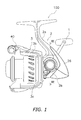
- FIG. 1 is a side view of a spinning reel according to a first exemplary embodiment of the present invention
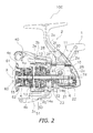
- FIG. 2 is a cross-sectional side view of the spinning reel
- FIG. 3 is a cross-sectional view of the spinning reel taken along a cutting line III-III in FIG. 1 ;
- FIG. 4 is an enlarged perspective view of a chassis
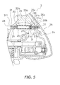
- FIG. 5 is an enlarged cross-sectional side view of a rear part of a reel unit
- FIG. 6 is a diagram corresponding to FIG. 5 and illustrates an enlarged cross-sectional side view of a rear part of a reel unit according to a modification of the first exemplary embodiment
- FIG. 7 is a diagram corresponding to FIG. 3 and illustrates a cross-sectional view of a spinning reel according to a second exemplary embodiment
- FIG. 8 is a diagram corresponding to FIG. 4 and illustrates an enlarged perspective view of a chassis according to the second exemplary embodiment
- FIG. 9 is a diagram corresponding to FIG. 5 and illustrates an enlarged cross-sectional side view of a rear part of a reel unit according to the second exemplary embodiment.
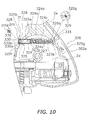
- FIG. 10 is a diagram corresponding to FIG. 5 and illustrates an enlarged cross-sectional side view of a rear part of a reel unit according to a third exemplary embodiment.
- a spinning reel 100 is a reel enabled to forwardly release a fishing line.
- the spinning reel 100 includes a handle 1, a reel unit 2 supporting the handle 1 in a rotatable state, a rotor 3, and a spool 4.
- the rotor 3 is rotatably supported at the front of the reel unit 2.
- the spool 4 is configured to wind the fishing line onto the outer peripheral surface thereof.
- the spool 4 is disposed at the front of the rotor 3 while being movable back and forth. It should be noted that the handle 1 is attachable to either of the right and left sides of the reel unit 2.
- the reel unit 2 includes a laterally opened chassis 2a with a mechanism attachment space 2d, a lid member 2b (see FIG. 3 ), a tubular part 25, a guard member 26 with a boss 26a, a screw member 27, a first seal member 28, and a second seal member 29.
- the chassis 2a has a first opening 30 and a second opening 31.
- the first opening 30 is opened through the front edge of the chassis 2a, while being continuing to the mechanism attachment space 2d.
- the second opening 31 is disposed oppositely to the first opening 30. The second opening 31 exteds through the rear edge of the chassis 2a, while being continuing to the mechanism attachment space 2d.
- the chassis 2a is made of light metal alloy such as magnesium alloy or aluminum alloy.
- a fishing rod attachment portion 2e is integrally formed with the upper part of the chassis 2a, while being extending back and forth in a T-shape.
- the chassis 2a accommodates a rotor drive mechanism 5 and an oscillating mechanism 6 within the mechanism attachment space 2d.
- the chassis 2a has a first flange 2f1 and a cylindrical portion 2g (see FIG. 4 ) on the front end thereof.
- the first flange 2f1 is a roughly semicircular portion forming a part of a circular flange 2f.
- the cylindrical portion 2g extends at its tip and has a diameter less than that of the flange 2f.
- the first opening 30 extends through the first flange 2f1.
- the first opening 30 is formed by a round hole with an inner diameter through which the screw member 27 passes.
- the first opening 30 is formed in a first protruding portion 2h protruding towards the second opening 31 from the first flange 2f as the front edge of the chassis 2a.
- the first opening 30 is closed with the first seal member 28 after attaching of the guard member 26 by the screw member 27.
- the second opening 31 is circularly formed in a second protruding portion 2i.
- the second protruding portion 2i is protruding towards the first opening 30 from the rear edge of the chassis 2a.
- the second opening 31 has a first hole portion 31a, a second hole portion 31b, and a wall portion 31c.
- the first hole portion 31a has a circular shape and extends through the rear edge of the chassis 2a.
- the second hole portion 31b is circularly formed from the first hole portion 31a towards the front edge of the chassis 2a.
- the wall portion 31c is a portion through which the second hole portion 31b extends.
- the boss 26a of the guard member 26 can be inserted into the first hole portion 31a.
- the second hole portion 31b has a diameter less than that of the first hole portion 31a.
- a threaded shaft 27b of the screw member 27 to be described can be inserted through the second hole portion 31b.
- the wall portion 31c is formed by a surface arranged perpendicular to
- the lid member 2b is detachably attached to the chassis 2a in order to close the mechanism attachment space 2d.
- the lid member 2b is made of, for instance, light metal alloy such as magnesium alloy or aluminum alloy.
- the lid member 2b is fixed to the chassis 2a by, for instance, two fixation bolts (not illustrated in the figures) at two front-side positions hidden by the rotor 3.
- the two fixation bolts on the front side are screwed into two threaded holes 18 (see FIG. 4 ) formed in the front part of the chassis 2a.
- the lid member 2b is fixed to the chassis 2a by a fixation bolt (not illustrated in the figures) at a rear-side position away from the rotor 3.
- the fixation bolt on the rear side is screwed into a threaded hole 19 formed in the rear part of the chassis 2a.
- the two fixation bolts on the front side are hidden by the rotor 3, whereas the fixation bolt on the rear side is covered with the guard member 26. Therefore, the fixation bolts for fixing the lid member 2b are not exposed to the outside of the reel unit 2.
- the lid member 2b has a second flange 2f2 on the front end thereof.
- the second flange 2f2 forms the flange 2f together with the first flange 2f1.
- the tubular part 25 is at least partially disposed between the first opening 30 and the second opening 31 within the mechanism attachment space 2d.
- the tubular part 25 is disposed within the mechanism attachment space 2d so as to be liquid-tight with respect to the mechanism attachment space 2d.
- the tubular part 25 is a member provided separately from the chassis 2a and is made of, for instance, synthetic resin such as polyamide resin or polyacetal resin.
- the tubular part 25 is disposed in the mechanism attachment space 2d of the chassis 2a.
- the tubular part 25 is disposed between the first opening 30 and the second opening 31.
- the tubular part 25 has a tube portion 25a, a bottom portion 25b, and a seal attachment portion 25c.
- the tube portion 25a is disposed in opposition to the first opening 30.
- a head 27a of the screw member 27 can be inserted in the tube portion 25a.
- the tube portion 25a has a hole with a diameter substantially the same as that of the first opening 30.
- the bottom portion 25b is disposed in opposition to the wall portion 31c.
- the bottom portion 25b has a through hole 25d.
- the threaded shaft 27b of the screw member 27 can pass through the through hole 25d.
- the bottom portion 25b can hold the head 27a of the screw member 27.
- the seal attachment portion 25c is protruding in a tubular shape towards the wall portion 31c from the bottom portion 25b.
- the seal attachment portion 25c is disposed while the tip thereof makes contact with the wall portion 31c.
- the through hole 25d is a hole with a diameter substantially the same as that of the second hole portion 31b of the second opening 31.
- the guard member 26 is a member attached to the chassis 2a and the lid member 2b from behind for covering the chassis 2a and the lid member 2b.
- the guard member 26 defines the outer contour of the rear part of the reel unit 2.
- the guard member 26 is attached to the lid member 2b and the chassis 2a including the fishing rod attached portion 2e through a packing (not illustrated in the figures) for shape alignment.
- the boss 26a of the guard member 26 is formed in a rod shape such that the screw member 27 is screwed into the center thereof.
- the boss 26a is formed in a forwardly protruding shape and can be inserted into the second opening 31 from the rear edge of the chassis 2a.
- the boss 26a can be inserted into the first hole portion 31a of the second opening 31.
- the boss 26a has a female threaded portion 26b in the center thereof.
- the screw member 27 is screwed into the female threaded portion 26b.
- the female threaded portion 26b is extending to an axially intermediate position in the boss 26a.
- the boss 26a has a length enabled to produce a clearance between the tip thereof and a step produced between the first hole portion 31a and the second hole portion 31b when the guard member 26 is fixed.
- the screw member 27 is a member having the head 27a and the threaded shaft 27b.
- the threaded shaft 27b has a diameter less than that of the head 27a and has a male threaded portion on the outer periphery thereof.
- the screw member 27 is a bolt member to be screwed into the female threaded portion 26b formed in the boss 26a.
- the screw member can be a self-tapping screw enabled to create a female threaded portion within the boss 26a.
- the screw member 27 is attached to the tubular part 25 before the spinning reel 100 is assembled.
- a tightening tool e.g., a screwdriver
- the tip of a tightening tool is inserted into the tubular part 25 via the first opening 30, and the screw member 27 is turned by the tightening tool.
- the screw member 27 is accordingly crewed into the boss 26a of the guard member 26. Consequently, the guard member 26 and the tubular part 25 are fixed to the chassis 2a.
- the first seal member 28 seals the clearance between the tubular part 25 and the first opening 30.
- the first seal member 28 is fitted to the inner peripheral surface of the first opening 30 and that of the tube portion 25a of the tubular part 25.
- the first seal member 28 is an elastic member made of synthetic rubber or the like.
- the first seal member 28 is a truncated cone member having a first end 28a and a second end 28b. The first end 28a is fitted into the first opening 30, while the second end 28b is fitted into the tube portion 25a of the tubular part 25.
- the first end 28a has an outer diameter greater than that of the second end 28b.
- the outer diameter of the first end 28a of the first seal member 28 is greater than the inner diameter of the first opening 30, whereas the outer diameter of the second end 28b is slightly less than the inner diameter of the tube portion 25a of the tubular part 25.
- the first seal member 28 is tapered and can be easily attached to the tubular part 25 via the first opening 30. With thus structured first seal member 28, liquid can be prevented from entering the mechanism attachment space 2d both from the inside of the tubular part 25 and from the first opening 30.
- the second seal member 29 seals the clearance between the tubular part 25 and the second opening 31.
- the second seal member 29 is an O-ring to be attached onto the seal attachment portion 25c.
- the wire diameter of the O-ring is greater than the protruding length of the seal attachment portion 25c.
- the screw member 27 for attaching the guard member 26 is covered with the first seal member 28. Therefore, a simple appearance can be obtained without exposing the screw member 27 to the outside. Further, the clearance between the first opening 30 and the tubular part 25 is sealed by the first seal member 28, whereas the clearance between the second opening 31 and the tubular part 25 is sealed by the second seal member 29. Therefore, liquid can be inhibited from entering the mechanism attachment space 2d, while the guard member 26 can be easily fixed without exposing the screw member 27 to the rear side. Further, the screw members for fixing the lid member 2b to the chassis 2a are also hidden by the rotor 3 and the guard member 26. Thus, such fixation bolts are not exposed to the outside.
- the rotor drive mechanism 5 includes a drive shaft 10, a drive gear 11, and a pinion gear 12.
- the drive shaft 10 is a member to which the handle 1 is fixed.
- the drive gear 11 is of a face gear type provided integrally with or separately from the drive shaft 10.
- the pinion gear 12 is meshed with the drive gear 11.
- the drive shaft 10 is rotatably supported by the reel unit 2 through a first bearing 16a and a second bearing 16b.
- the first bearing 16a is attached into a first boss 17a disposed inside the chassis 2a.
- the second bearing 16b is attached into a second boss 17b disposed inside the lid member 2b.
- the drive gear 11 is disposed while the outer peripheral part thereof is opposed to the tubular part 25 disposed inside the chassis 2a in the axial direction of the drive shaft 10.
- the tubular part 25 is disposed in avoidance of contact with the drive gear 11.
- the drive gear 11 of the present exemplary embodiment has a larger diameter and a greater number of teeth than a well-known drive gear.
- the pinion gear 12 is formed in a tubular shape, and the front part thereof is fixed to the rotor 3 by a nut 13 while penetrating through the center part of the rotor 3. Further, the axially intermediate part and the axially rear end of the pinion gear 12 are rotatably supported by the reel unit 2 through a bearing 14a and a bearing 14b, respectively.
- the oscillating mechanism 6 is a mechanism configured to move a spool shaft 15 coupled to the center part of the spool 4 through a drag mechanism 60 in a back-and-forth direction and thereby move the spool 4 in the same direction as the spool shaft 15.
- the oscillating mechanism 6 includes a traverse cam shaft 21, a slider 22, and an intermediate gear 23.
- the traverse cam shaft 21 is disposed below and in parallel to the spool shaft 15.
- the slider 22 is configured to move along the traverse cam shaft 21 in the back-and-forth direction.
- the intermediate gear 23 is fixed to the tip of the traverse cam shaft 21.
- the rear end of the spool shaft 15 is fixed to the slider 22 while being non-rotatable.
- the intermediate gear 23 is meshed with the pinion gear 12.
- the rotor 3 is rotatable with respect to the reel unit 2 about a first axis X arranged in the back-and-forth direction.
- the rotor 3 is coupled to the pinion gear 12 while being unitarily rotatable therewith.
- the rotor 3 includes a rotor body 3a, a first rotor arm 3b, and a second rotor arm 3c.
- the rotor body 3a is formed in a roughly tubular shape and is coupled to the pinion gear 12.
- the first and second rotor arms 3b and 3c are extending from the both lateral sides of the rotor body 3a.
- the rotor 3 includes a bail arm 40 pivotably coupled to the first and second rotor arms 3b and 3c.
- the bail arm 40 is disposed for winding the fishing line onto the spool 4.
- the rotor 3 is configured to be switchable between a reverse rotation prevention state and a reverse rotation permission state by an anti-reverse mechanism 50 including a roller-type one-way clutch 51.
- the switching operation can be executed by a switch lever 52 disposed in the lower part of the reel unit 2.
- the spool 4 is disposed between the first and second rotor arms 3b and 3c of the rotor 3.
- the spool 4 is mounted to the tip of the spool shaft 15 through the drag mechanism 60.
- the spool 4 has a bobbin trunk 4a, a skirt 4b, and a flange 4c.
- the bobbin trunk 4a is a portion that the fishing line is wound about the outer periphery thereof.
- the skirt 4b is a tubular portion integrally formed with the rear end of the bobbin trunk 4a.
- the flange 4c is a large-diameter portion disposed on the front end of the bobbin trunk 4a.
- the drag mechanism 60 is configured to brake rotation of the spool 4.
- the drag mechanism 60 includes a drag regulation knob 61 and a braking part 62.
- the drag regulation knob 61 is screwed onto the tip of the spool shaft 15.
- the braking part 62 is configured to brake the spool 4 while being pressed by the drag regulation knob 61.
- the rotor drive mechanism 5 and the oscillating mechanism 6 are attached to the inside of the reel unit 2, while the anti-reverse mechanism 50 is attached to the inside of the cylindrical portion 2g.
- the screw member 27 and the second seal member 29 are attached to the tubular part 25, and the tubular part 25 is temporarily disposed within the mechanism attachment space 2d of the chassis 2a by the screw member 27.
- the chassis 2a is covered with the lid member 2b.
- the lid member 2b is then fixed to the chassis 2a by the fixation bolts (not illustrated in the figures).
- the guard member 26 is attached to the chassis 2a and the lid member 2b from behind. At this time, the boss 26a of the guard member 26 is inserted into the first hole portion 31a of the second opening 31.
- the screw member 27 is screwed into the boss 26a using the tightening tool (e.g., a screwdriver) inserted through the first opening 30.
- the guard member 26 and the tubular part 25 are thereby fixed to the chassis 2a. With the aforementioned procedure, an assembling work of the reel unit 2 is finished.
- the clearance between the tubular part 25 and the first opening 30 is sealed by the first seal member 28, whereas the clearance between the tubular part 25 and the second opening 31 is sealed by the second seal member 29.
- the guard member 26 and the tubular part 25 are fixed to the chassis 2a by screwing the single screw member 27, disposed inside the tubular part 25, into the boss 26a inserted into the second opening 31 from the rear side. Therefore, the guard member 26 can be easily fixed to the chassis 2a without exposing the screw member 27 to the rear side, while liquid can be inhibited from entering the mechanism attachment space 2d.
- the tip of the seal attachment portion 25c of the tubular part 25 makes contact with the wall portion 31c of the second opening 31.
- the present invention is not limited to the structure.
- a second opening 131 is formed only by a first hole portion 131a that a boss 126a can be inserted therein.
- a seal attachment portion 125c of a tubular part 125 is fitted into the first hole portion 131a of the second opening 131.
- the seal attachment portion 125c has an annular groove 125e on the outer peripheral surface thereof for attaching thereto a second seal member 129.
- the second seal member 129 seals the clearance between the seal attachment portion 125c and the inner peripheral surface of the first hole portion 131a. Further, a bottom portion 125b of the tubular part 125 makes contact with the wall portion 31c of the second opening 131.
- the other components are the same as the corresponding ones of the first exemplary embodiment. Therefore, the same reference numerals are assigned to the same components as those used in the first exemplary embodiment, and explanation thereof will be hereinafter omitted.
- the tubular part 125 can be easily held when temporarily held within the mechanism attachment space 2d.
- the tubular part 25 is disposed separately from the chassis 2a.
- a tubular part 225 of a reel unit 202 of a spinning reel 300 is integrally formed with a chassis 202a.
- a first opening 230 and a second opening 231 are continuing to a through hole 224a without being continuing to the mechanism attachment space 2d.
- the tubular part 225 has the through hole 224a and a penetrating part 224.
- the through hole 224a penetrates through the mechanism attachment space 2d in the back-and-forth direction.
- the penetrating part 224 is sealed to be liquid-tight with respect to the mechanism attachment space 2d.
- the first flange 2f1 has the first opening 230 formed by a round hole.
- the first opening 230 is configured to continue to the penetrating part 224.
- the first opening 230 is closed by a cap 239 after a guard member 226 is attached by a screw member 227.
- the chassis 202a has a protruding part 232 formed on the upper part of the inner lateral surface.
- the protruding part 232 is formed in a shape protruding towards the lid member 2b.
- the protruding part 232 is extending along the back-and-forth direction, while connecting the front edge and the rear edge of the chassis 202a.
- the through hole 224a of the penetrating part 224 is formed in the protruding part 232, while penetrating through the front edge and the rear edge of the chassis 202a. Therefore, the penetrating part 224 is sealed to be liquid-tight with respect to the mechanism attachment space 2d.
- the through hole 224a has a first portion 224b, a second portion 224c, and a third portion 224d.
- the first portion 224b is continuing to the first opening 230.
- the first portion 224b is a hole formed in the front part of the chassis 202a and a head 227a of the screw member 227 is inserted in the hole.
- the second portion 224c is a hole formed in the rear part of the cassis 202a and a boss 226a (to be described) of the guard member 226 is inserted in the hole.
- the second portion 224c is continuing to the second opening 231.
- the third portion 224d is disposed between the first portion 224b and the second portion 224c.
- the third portion 224d is a hole with a diameter less than that of the first portion 224b and a shaft 227b of the screw member 227 is inserted in the hole.
- the head 227a of the screw member 227 is held by a step produced between the first portion 224b and the third portion 224d.
- the shaft 227b penetrates through the third portion 224d and reaches the second portion 224c.
- the boss 226a is inserted into the second portion 224c.
- the tip of the boss 226a is disposed rearwards of a step produced between the second portion 224c and the third portion 224d.
- an intermediate portion 232a of the protruding part 232 is formed along with the shape of the through hole 224a and has a diameter less than that of the both sides thereof.
- the protruding part 232 and the penetrating part 224 are formed with an even thickness. Therefore, sink marks are less easily produced in die molding, and further, it is possible to prevent deformation of the holes of the penetrating part 224 attributed to such sink marks.
- the guard member 226 is structured similarly to the guard member 26 of the first exemplary embodiment. It should be noted that the boss 226a has a length greater than that of the boss 26a of the first exemplary embodiment.
- the boss 226a is formed in such a shape that it can protrude from the rear part of the chassis 202a towards the through hole 224a of the penetrating part 224. As described above, the boss 226a can be inserted into the second portion 224c of the penetrating part 224.
- the boss 226a has a screwed recess 226b in the center thereof.
- the screw member 227 is screwed into the screwed recess 226b.
- the screwed recess 226b is extending to an axially intermediate position in the boss 226a.
- the screw member 227 is a member having the head 227a and the shaft 227b.
- the shaft 227b has a diameter less than that of the head 227a, and has a male threaded portion on the outer peripheral part thereof.
- a self-tapping screw enabled to form a female threaded portion, is used as the screw member 227.
- a normal bolt screwed into a female threaded portion, can be used as the screw member.
- the female threaded portion is formed on the screwed recess.
- the screw member 227 is inserted into the penetrating part 224 from the front part of the chassis 202a, and is screwed into the boss 226a of the guard member 226. Accordingly, the guard member 226 is fixed to the chassis 202a.
- the screw member 227 In the reel unit 202, the screw member 227, provided for attaching of the guard member 226, is covered with the cap 239. Therefore, a simple appearance can be obtained without exposing the screw member 227 to the outside. Further, the screw member 227 is attached to the penetrating part 224 sealed to be liquid-tight with respect to the mechanism attachment space 2d. Yet further, the boss 226a of the guard member 226 is also disposed in the penetrating part 224. Under the condition, the guard member 226 is fixed to the chassis 202a by the screw member 227. Therefore, the guard member 226 can be easily fixed without exposing the screw member 227 to the rear side, while liquid can be inhibited from entering the mechanism attachment space 2d. Further, the screw members, provided for fixing the lid member 2b to the chassis 202a, are also hidden by the rotor 3 and the guard member 226. Thus, these screw members are also not exposed to the outside.
- the rotor drive mechanism 5 and the oscillating mechanism 6 are attached to the inside of the reel unit 202, while the anti-reverse mechanism 50 is attached to the inside of the cylindrical portion 2g.
- the chassis 202a is covered with the lid member 2b.
- the lid member 2b is then fixed to the chassis 202a by the fixation bolts (not illustrated in the figures).
- the guard member 226 is attached to the chassis 202a and the lid member 2b from behind. At this time, the boss 226a of the guard member 226 is inserted into the second portion 224c of the through hole 224a.
- the screw member 227 is inserted from the first portion 224b, and is screwed into the boss 226a using a tool (e.g., a screwdriver).
- the guard member 226 is thereby fixed to the chassis 202a. With the aforementioned procedure, an assembling work of the reel unit 202 is finished.
- the guard member 226 is fixed to the chassis 202a by screwing the single screw member 227 inserted from the front part into the boss 226a inserted from the rear part within the penetrating part 224 sealed to be liquid tight with respect to the mechanism attachment space 2d. Therefore, the guard member 226 can be easily fixed without exposing the screw member 227 to the rear side, while liquid can be prevented from entering the mechanism attachment space 2d.
- the tubular part 25 is disposed only in the mechanism attachment space 2d.
- the present invention is not limited to the structure.
- a tubular part 325 is disposed while penetrating through first and second openings 330 and 331 of a chassis 302a. Therefore, the tubular part 325 is disposed across the mechanism attachment space 2d.
- the first opening 330 has a third hole portion 330a with a large diameter and a fourth hole portion 330b with a small diameter.
- the second opening 331 is formed such that the tubular part 325 penetrates therethrough.
- the tubular part 325 has a tube portion 325a and a brimmed portion 325b.
- the tube portion 325a has a diameter less than that of the brimmed portion 325b.
- the brimmed portion 325b is a large-diameter portion for a positioning purpose, and is held by a step produced between the third hole portion 330a and the fourth hole portion 330b.
- the tubular part 325 further includes a penetrating part 324 having a through hole 324a.
- the through hole 324a has a first portion 324b, a second portion 324c and a third portion 324d.
- the first portion 324b has an inner diameter that a head 327a of a screw member 327 can be inserted therein.
- the second portion 324c has an inner diameter that a boss 326a of a guard member 326 can be inserted therein.
- the third portion 324d is a small-diameter portion disposed between the first portion 324b and the second portion 324c.
- the third portion 324d has an inner diameter that a threaded shaft 327b of the screw member 327 can pass therethrough.
- the rear end of the tube portion 325a is protruding rearwards of the chassis 302a.
- the tip of the boss 326a of the guard member 326 is disposed rearwards of a step produced between the second portion 324c and the third portion 324d.
- the head 327a of the screw member 327 is held by the step produced between the first portion 324b and the third portion 324d.
- the threaded shaft 327b is screwed into the boss 326a while penetrating the third portion 324d.
- the screw member 327 is a self-tapping screw.
- a first seal member 328 is disposed between the outer peripheral surface of the front part of the tube portion 325a and the first opening 330 in order to seal the clearance between the tubular part 325 and the first opening 330. As illustrated in the enlarged view of FIG. 10 , the first seal member 328 is attached to a first annular groove 325f formed on the outer peripheral surface of the tube portion 325a.
- a second seal member 329 is disposed between the outer peripheral surface of the rear part of the tube portion 325a and the second opening 331 in order to seal the clearance between the tubular part 325 and the second opening 331.
- the second seal member 329 is attached to a second annular groove 325g formed on the outer peripheral surface of the rear part of the tube portion 325a.
- the first seal member 328 and the second seal member 329 are O-rings.
- the front-side opened part of the first portion 324b of the tubular part 325 is closed with a cap member 339 made of, for instance, elastic material.
- the tubular part 325 to which the first and second seal members 328 and 329 are attached, is preliminarily inserted from the first opening 330, is penetrated through the second opening 331, and is pressed into the chassis 302a until the brimmed portion 325b makes contact with the step produced between the third hole portion 330a and the fourth hole portion 330b.
- the boss 326a of the guard member 326 is inserted into the second portion 324c of the penetrating part 324.
- the screw member 327 is inserted from the first portion 324b, and is screwed until the guard member 326 makes contact with the chassis 302a and a lid member (not illustrated in the figure) while the brimmed portion 325b makes contact with the step produced between the third hole portion 330a and the fourth hole portion 330b of the first opening 330. Accordingly, the guard member 326 and the tubular part 325 are fixed to the chassis 302a.
- the front-side and rear-side outer peripheral portions of the tubular part 325 are sealed with the first seal member 328 and the second seal member 329. Therefore, liquid can be prevented from entering the mechanism attachment space 2d through the clearance between the tubular part 325 and the first opening 330 and that between the tubular part 325 and the second opening 331. Further, the tubular part 325 is disposed while penetrating through the front edge and the rear edge of the chassis 302a. Therefore, even when entering the inside of the tubular part 325, liquid can be prevented from entering the mechanism attachment space 2d.
- the other components are the same as the corresponding ones of the first exemplary embodiment. Therefore, detailed explanation thereof will be hereinafter omitted.
- the tubular part 325 is detachably attached to the first opening 330 and the second opening 331.
- the tubular part 325 can be fixed to the first opening 30 and the second opening 331 by an arbitrary fixation method such as adhesion, press-fitting or the like.
- the brimmed portion 325b for a positioning purpose is not required to be provided.
- the mechanism attachment space 2d can be liquid tight by fixing the tubular part 325 without using a seal member.
- the reel unit 2 is attachable to a fishing rod and is used for the spinning reel 100 configured to forwardly release the fishing line.
- the reel unit 2 includes the chassis 2a, the lid member 2b, the guard member 26, the tubular part 25 and the screw member 27.
- the chassis 2a has the mechanism attachment space 2d, the first opening 30 and the second opening 31.
- the mechanism attachment space 2d is configured at a lateral side of the chassis 2a.
- the first opening 30 is extending through the front edge of the chassis 2a while being continuing to the mechanism attachment space 2d.
- the second opening 31 is disposed on the opposite side of to the first opening 30.
- the second opening 31 is extending through the rear edge of the chassis 2a while being continuing to the mechanism attachment space 2d.
- the lid member 2b is detachably attached to the chassis 2a for closing the mechanism attachment space 2d.
- the guard member 26 is attached to the chassis 2a and the lid member 2b from behind for covering the chassis 2a and the lid member 2b.
- the guard member 26 has the boss 26a which is inserted into the second opening 31 from the rear edge of the chassis 2a.
- the tubular part 25 is disposed between the first opening 30 and the second opening 31 within the mechanism attachment space 2d so as to be liquid-tight with respect to the mechanism attachment space 2d.
- the screw member 27 passes through the first opening 30, and is screwed into the boss 26a while the head 27a thereof is held inside the tubular part 25.
- the guard member 26 is fixed to the chassis 2a by the single screw member 27 that the head 27a thereof is held by the tubular part 25.
- the tubular part 25 is disposed between the first opening 30 and the second opening 31 within the mechanism attachment space 2d so as to be liquid-tight with respect to the mechanism attachment space 2d. Therefore, liquid is prevented from entering the mechanism attachment space 2d from the inside of the tubular part 25.
- the guard member 26 can be fixed to the chassis 2a by the single screw member. Therefore, liquid can be inhibited from entering the mechanism attachment space 2d, while the guard member 26 can be easily fixed without exposing the screw member 27 to the rear side.
- the first opening 30 and the second opening 31 are respectively continuing to the mechanism attachment space 2d.
- the tubular part 25 is at least partially disposed between the first opening 30 and the second opening 31 within the mechanism attachment space 2d.
- the reel unit 2 further includes the first seal member 28 and the second seal member 29.
- the first seal member 28 seals the clearance between the tubular part 25 and the first opening 30.
- the second seal member 29 seals the clearance between the tubular part 25 and the second opening 31.
- the second opening 31 has the first hole portion 31a, the second hole portion 31b and the wall portion 31c.
- the first hole portion 31a is extending to the rear edge of the chassis 2a and the boss 26a is inserted in the first hole portion 31a.
- the second hole portion 31b is formed towards the front edge of the chassis 2a from the first hole portion 31a and the threaded shaft 27b of the screw member 27 passes therethrough.
- the second hole portion 31b has a diameter less than that of the first hole portion 31a.
- the wall portion 31c has the second hole portion 31b extending therethrough, and has a surface disposed perpendicular to the second hole portion 31b.
- the tubular part 25 is disposed within the mechanism attachment space 2d.
- the tubular part 25 has the tube portion 25a and the bottom portion 25b.
- the tube portion 25a is disposed in opposition to the first opening 30.
- the the head 27a of the screw member 27 is inserted in the tube portion 25a.
- the bottom portion 25b is disposed in opposition to the wall portion 31c.
- the bottom portion 25b has the through hole 25d through which the threaded shaft 27b passes.
- the bottom portion 25b is enabled to hold the head 27a.
- the first seal member 28 is fitted to the first opening 30 and the tube portion 25a.
- the first seal member 28 is a truncated cone member made of elastic material, and the first end 28a thereof fitted to the first opening 30 has a diameter greater than that of the second end 28b thereof fitted to the tube portion 25a.
- the first seal member 28 is tapered that is attached to the tube portion 25a through the first opening 30. Therefore, the first seal member 28 can be easily attached to the tube portion 25a.
- the second seal member 29 is disposed between the wall portion 31c and the bottom portion 25b.
- the tubular part 25 has the seal attachment portion 25c circularly protruding towards the wall portion 31c from the bottom portion 25b.
- the second seal member 29 is attached onto the outer peripheral surface of the seal attachment portion 25c.
- the second seal member 29, disposed between the wall portion 31c and the bottom portion 25b, is attached to the seal attachment portion 25c. Therefore, the second seal member 29 can be reliably attached thereto.
- the second seal member 29 is an O-ring attachable to the seal attachment portion 25c.
- the clearance between the tubular part 25 and the second opening 31 can be sealed by a commercially available O-ring.
- the tubular part 325 is detachably attached to the first opening 330 and the second opening 331.
- attaching of the tubular part 325 can be easily done because of the structure that the tubular part 325 is detachably attached to the first opening 330 and the second opening 331.
- the tubular part 225 includes the penetrating part 224 having the through hole 224a.
- the through hole 224a penetrates through the mechanism attachment space 2d in the back-and-forth direction, while being continuing to the first opening 230 and the second opening 231.
- the penetrating part 224 is sealed to be liquid-tight with respect to the mechanism attachment space 2d.
- the guard member 226 When the guard member 226 is fixed to the chassis 202a in the reel unit 202, the boss 226a of the guard member 226 is inserted into the through hole 224a from the rear side. Under the condition, the screw member 227 is inserted into the through hole 224a from the front side and is screwed into the boss 226a. Accordingly, the guard member 226 is fixed to the chassis 202a.
- the penetrating part 224 is herein sealed to be liquid-tight with respect to the mechanism attachment space 2d. Therefore, liquid is prevented from entering the mechanism attachment space 2d through the penetrating part 224.
- the penetrating part 224 (324) is disposed only in the chassis 202a (302a). In this case, the penetrating part 224 (324) is disposed only in the chassis 202a (302a) without being disposed in the lid member 2b. Therefore, it is not required to provide a structure using another seal member for making the penetrating part 224 (324) liquid-tight with respect to the mechanism attachment space 2d. Therefore, the guard member 226 (326) can be more easily fixed.
- the chassis 202a has the protruding part 232 protruding towards the lid member 2b from the inner lateral surface of the chassis 202a.
- the protruding part 232 is extending along the back-and-forth direction while connecting the front edge and the rear edge of the chassis 202a.
- the through hole 224a is disposed within the protruding part 232 while penetrating through the front edge and the rear edge of the chassis 202a along the back-and-forth direction.
- the chassis 202a can be fabricated using a simple die configured to be split in the right-and-left direction (i.e., a drive shaft direction) even when the chassis 202a is designed to include the protruding part 232.
- the through hole 224a has the first portion 224b, the second portion 224c and the third portion 224d.
- the first portion 224b is disposed in the front part of the through hole 224a and the head 227a of the screw member 227 is inserted in the through hole 224a.
- the second portion 224c is disposed in the rear part of the through hole 224a and the boss 226a is inserted the through hole 224a.
- the third portion 224d is disposed between the first portion 224b and the second portion 224c and has a diameter less than that of the first portion 224b and that of the second portion 224c.
- the head 227a of the screw member 227 is inserted into the first portion 224b while being held by the step produced between the first portion 224b and the third portion 224d. Further, the boss 226a is inserted into the second portion 224c.
- the length of the boss 226a is preferably set for producing a clearance between the tip of the boss 226a and the step produced between the second portion 224c and the third portion 224d.
- the penetrating part 324 is detachably attached to the first opening 330 and the second opening 331. In this case, attaching of the penetrating part 324 can be easily done due to the structure that the penetrating part 324 is attached to the first opening 330 and the second opening 331.
- the spinning reel includes the spool 4, the rotor 3 for winding the fishing line onto the spool 4, and the drive gear 11 for driving the rotor 3.
- the tubular part 25 is disposed in a position where it is opposed to the drive gear 11 in the axial direction of the drive gear 11.
- the tubular part 25 and the drive gear 11 can be disposed in alignment in the axial direction of the drive gear 11. Therefore, the tubular part 25 does not spatially interfere with the drive gear 11. Therefore, increase in diameter of the drive gear 11 can be achieved even when the tubular part 25 is provided.
- the chassis 2a has the fishing rod attached portion 2e attachable to a fishing rod.
- the chassis 2a with relatively high stiffness is provided with the fishing rod attached portion 2e to which force is applied from the fishing rod during fishing. Therefore, it is easy to reliably obtain such strength as required for the fishing rod attached portion 2e.
- the spinning reel 100 includes the reel unit 2, the spool 4, the rotor 3 and the drive gear 11.
- the spool 4 is mounted to the reel unit 2 while being enabled to reciprocate back and forth.
- the rotor 3 is rotatably supported by the reel unit 2 for winding the fishing line onto the spool 4.
- the spinning reel 100 can implement a spinning reel for achieving the aforementioned advantageous effects.
- the first exemplary embodiment describes an 0-ring as the second seal member 29.
- the second seal member is not limited to the O-ring.
- the second seal member can be a ring-shaped sheet packing to be disposed between the wall portion 31c and the bottom portion 25b.
- the fishing rod attached portion 2e is integrally formed with the chassis 2a.
- the fishing rod attached portion 2e can be integrally formed with the lid member 2b.
- the protruding part 232 is protruding from the inner lateral surface of the chassis 202a.
- the present invention is not limited to the structure.
- the protruding part can be downwardly protruding from the inner top surface of the chassis 202a.
- the protruding part 232 is preferably protruding towards the lid member 2b for avoiding complication of a die to be used.
- the clearances between the tubular part and the chassis are sealed by the first seal member and the second seal member. Therefore, liquid is prevented from entering the mechanism attachment space from the inside of the tubular part.
- the guard member can be fixed to the chassis, while the tubular part can be fixed to the chassis. Accordingly, liquid can be inhibited from entering the mechanism attachment space, while the guard member can be easily fixed without exposing the screw member to the rear side.
Landscapes
- Life Sciences & Earth Sciences (AREA)
- Environmental Sciences (AREA)
- Animal Husbandry (AREA)
- Biodiversity & Conservation Biology (AREA)
Abstract
Description
- The present invention relates to a spinning reel that is attachable to a fishing rod and is configured to forwardly release a fishing line, and relates to a spinning-reel reel unit.
- A reel unit of a spinning reel includes a chassis, a lid member, and a guard member. The chassis has an opening. The lid member is fixed to the chassis for closing the opening. A mechanism attachment space can be formed between the lid member and the chassis. The guard member covers the rear part of the chassis and that of the lid member. The guard member is screwed to the chassis. A well-known type of reel unit has a structure in which the guard member is provided with a forwardly protruding boss so as to be screwed to the chassis (e.g., see specification of Japan Patent No.
4804330 - In such well-known structure, the screw members for fixation of the guard member are not exposed to the rear side of the reel unit. However, two screw members are required for fixation of the guard member. A fixation work for the guard member will be complicated. Further, the cap member is attached to the through hole. However, chances are that liquid enters the mechanism attachment space through a clearance between the chassis and the boss.
- It is an adavantage of the present invention to inhibit liquid from entering a mechanism attachment space and to easily fix a guard member without exposing a screw member to the rear side.
- A reel unit for a spinning reel is provided. The spinning reel is attachable to a fishing rod. The spinning reel is configured to forwardly release a fishing line from a front side of the spinning reel. The reel unit includes a chassis, a lid member, a guard member, a tubular part, and a screw member. The chassis includes a mechanism attachment space at a lateral side thereof, a first opening extending through a front edge of the chassis, and a second opening extending through a rear edge of the chassis. The second opening is disposed on an opposite side of the first opening. The lid member is detachably attached to the chassis to close the mechanism attachment space. The guard member includes a boss being inserted into the second opening from the rear edge of the chassis. The guard member is attached to the chassis and the lid member from behind to cover the chassis and the lid member. The tubular part is disposed between the first opening and the second opening within the mechanism attachment space and arranged to be liquid-tight. The screw member passes through the first opening and being screwed into the boss. The screw member having a head being held inside the tubular part.
- In the present reel unit, the guard member is fixed to the chassis by means of the single screw member that the head thereof is held by the tubular part. The tubular part is disposed between the first opening and the second opening within the mechanism attachment space so as to be liquid-tight with respect to the mechanism attachment space. Therefore, liquid is prevented from entering the mechanism attachment space from the inside of the tubular part. Further, the guard member can be fixed to the chassis by means of the single screw member. With the structure, liquid can be inhibited from entering the mechanism attachment space, while the guard member can be easily fixed without exposing the screw member to the rear side.
- In the reel unit, the first opening and the second opening may continue to the mechanism attachment space. At least a part of the tubular part is disposed between the first opening and the second opening within the mechanism attachment space. The reel unit further includes a first seal member and a second seal member. The first seal member is configured to seal a clearance between the tubular part and the first opening. The second seal member is configured to seal a clearance between the tubular part and the second opening.
- In the present reel unit, the clearance between the tubular part and the first opening is sealed by means of the first seal member, while the clearance between the tubular part and the second opening is sealed by means of the second seal member. Therefore, liquid is prevented from entering the mechanism attachment space from the inside of the tubular part.
- In the reel unit, the second opening may include a first hole portion, a second hole portion and a wall portion. The first hole portion is extending through the rear edge of the chassis. The first hole portion allows the boss to be inserted therein. The second hole portion is formed from the first hole portion towards the front edge of the chassis. The second hole portion allows a threaded shaft of the screw member to pass therethrough. The second hole portion has a diameter less than that of the first hole portion. The wall portion has the second hole portion opened therethrough. The wall portion includes a surface disposed perpendicular to the second hole portion. The tubular part is disposed within the mechanism attachment space. The tubular part includes a tube portion and a bottom portion. The tube portion is disposed in opposition to the first opening. The tube portion allows the head of the screw member to be inserted therein. The bottom portion is disposed in opposition to the wall portion. The bottom portion has a through hole allowing the threaded shaft of the screw member to pass therethrough. The bottom portion allows the head of the screw member to be held thereon. The first seal member is fitted to the first opening and the tubular part.
- In this case, the tubular part is disposed in the mechanism attachment space. Therefore, the tubular part can be disposed within the mechanism attachment space before the lid member is fixed to the chassis Further, the first seal member is fitted to the first opening and the tube portion Therefore, the tubular part can be supported by the first seal member.
- In the reel unit, the first seal member may be a truncated cone member made of an elastic material. The first seal member has one end fitted to the first opening and the other end fitted to the tube portion. The one end has a diameter greater than that of the other end. In this case, the first seal member, attached to the tube portion through the first opening, is formed in a tapered shape. Therefore, the first seal member can be easily attached to the tube portion.
- In the reel unit, the second seal member may disposed between the wall portion and the bottom portion. The tubular part has a seal attachment portion circularly protruded from the bottom portion towards the wall portion. The second seal member is attached onto an outer peripheral surface of the seal attachment portion. In this case, the second seal member, disposed between the wall portion and the bottom portion, is attached to the seal attachment portion. Therefore, the second seal member can be reliably attached thereto.
- In the reel unit, the second seal member may be an O-ring attachable to the seal attachment portion. In this case, the clearance between the tubular part and the second opening can be sealed by means of a commercially available seal member.
- In the reel unit, the tubular part may be detachably attached to the first opening and the second opening. In this case, the tubular part is detachably attached to the first opening and the second opening. Therefore, the tubular part can be easily attached thereto.
- In the reel unit, the tubular part may include a penetrating part. The penetrating part is sealed to be liquid-tight with respect to the mechanism attachment space. The penetrating part has a through hole. The through hole penetrates through the mechanism attachment space in a back-and-forth direction, while being communicated with the first opening and the second opening.
- In the present reel unit, the boss of the guard member is inserted into the through hole from the rear side when the guard member is fixed to the chassis. Under the condition, the screw member is inserted into the through hole from the front side and is screwed into the boss. Accordingly, the guard member is fixed to the chassis. At this time, the penetrating part is sealed to be liquid-tight with respect to the mechanism attachment space. Therefore, liquid is prevented from entering the mechanism attachment space from the penetrating part.
- The guard member is herein fixed to the chassis by screwing the single screw member inserted from the front side into the boss inserted from the rear side, within the through hole of the penetrating part sealed to be liquid-tight with respect to the mechanism attachment space. Therefore, liquid can be inhibited from entering the mechanism attachment space, while the guard member can be easily fixed without exposing the screw member to the rear side.
- In the reel unit, the penetrating part may be only provided for the chassis. In this case, the penetrating part is only provided for the chassis without being provided for the lid member. Therefore, it is not required to form a structure for sealing the penetrating part to be liquid-tight with respect to the mechanism attachment space by means of another seal member. Therefore, the guard member can be further easily fixed.
- In the reel unit, the chassis may have a protruded part protruded from an inner lateral surface of the chassis towards the lid member. The protruded part is extended along the back-and-forth direction while connecting the front edge and the rear edge of the chassis. The through hole is disposed within the protruded part along the back-and-forth direction while penetrating through the front edge and the rear edge of the chassis. In this case, the protruded part is disposed within the chassis while being protruded towards the lid member. Further, the through hole is disposed within the protruded part while penetrating through the front edge and the rear edge of the chassis. Therefore, it is possible to easily form a structure for making the penetrating part liquid-tight with respect to the mechanism attachment space. Further, when being fabricated by means of die forming, the chassis can be fabricated using a simple die configured to be split in the right-and-left direction (i.e., a drive shaft direction) even when the chassis is designed to include the protruded part.
- In the reel unit, the through hole may have a first portion, a second portion and a third portion. The first portion is disposed in a front part of the through hole, and allows the head of the screw member to be inserted therein. The second portion is disposed in a rear part of the through hole, and allows the boss to be inserted therein. The third portion is disposed between the first portion and the second portion. The third portion allows the shaft of the screw member to be inserted therein. The third portion has a diameter less than that of the first portion.
- In the through hole, the head of the screw member is inserted into the first portion, while being held by a step produced between the first portion and the third portion. Further, the boss is inserted into the second portion. The length of the boss is preferably set for producing a clearance between the tip of the boss and a step produced between the second portion and the third portion.
- In the reel unit, the penetrating part may be detachably attached to the first opening and the second opening. In this case, attaching of the penetrating part can be easily done due to the structure that the penetrating part is attached to the first opening and the second opening.
- The spinning reel includes a spool, a rotor configured to wind the fishing line onto the spool, and a drive gear configured to drive the rotor. In the reel unit, the tubular part may be positioned in opposition to the drive gear in an axial direction of the drive gear. In this case, the tubular part and the drive gear can be axially disposed in alignment. Therefore, the tubular part does not spatially interfere with the drive gear. Accordingly, increase in diameter of the drive gear can be achieved even when the tubular part is provided.
- In the reel unit, the chassis may have a fishing rod attachment portion attachable to the fishing rod. In this case, the chassis having relatively high stiffness is provided with the fishing rod attachment portion to which force is applied from the fishing rod during fishing. Therefore, it is easy to reliably achieve such strength as to be required for the fishing rod attached portion.
- A spinning reel may include the aforementioned reel unit, a spool, a rotor and a drive gear. The spool is attached to the reel unit while being allowed to be reciprocated back and forth. The rotor is rotatably supported by the reel unit for winding the fishing line onto the spool. The drive gear is configured to drive the rotor.
- The present spinning reel can implement a spinning reel for achieving the aforementioned advantages effects.
- Referring now to the attached drawings which form a part of this original disclosure:
-
FIG. 1 is a side view of a spinning reel according to a first exemplary embodiment of the present invention; -
FIG. 2 is a cross-sectional side view of the spinning reel; -
FIG. 3 is a cross-sectional view of the spinning reel taken along a cutting line III-III inFIG. 1 ; -
FIG. 4 is an enlarged perspective view of a chassis; -
FIG. 5 is an enlarged cross-sectional side view of a rear part of a reel unit; -
FIG. 6 is a diagram corresponding toFIG. 5 and illustrates an enlarged cross-sectional side view of a rear part of a reel unit according to a modification of the first exemplary embodiment; -
FIG. 7 is a diagram corresponding toFIG. 3 and illustrates a cross-sectional view of a spinning reel according to a second exemplary embodiment; -
FIG. 8 is a diagram corresponding toFIG. 4 and illustrates an enlarged perspective view of a chassis according to the second exemplary embodiment; -
FIG. 9 is a diagram corresponding toFIG. 5 and illustrates an enlarged cross-sectional side view of a rear part of a reel unit according to the second exemplary embodiment; and -
FIG. 10 is a diagram corresponding toFIG. 5 and illustrates an enlarged cross-sectional side view of a rear part of a reel unit according to a third exemplary embodiment. - As illustrated in
FIG. 1 , a spinningreel 100 according to a first exemplary embodiment of the present invention is a reel enabled to forwardly release a fishing line. The spinningreel 100 includes ahandle 1, areel unit 2 supporting thehandle 1 in a rotatable state, arotor 3, and a spool 4. Therotor 3 is rotatably supported at the front of thereel unit 2. The spool 4 is configured to wind the fishing line onto the outer peripheral surface thereof. The spool 4 is disposed at the front of therotor 3 while being movable back and forth. It should be noted that thehandle 1 is attachable to either of the right and left sides of thereel unit 2. - As illustrated in
FIGS. 2 and3 , thereel unit 2 according to the fist exemplary embodiment of the present invention includes a laterally openedchassis 2a with amechanism attachment space 2d, alid member 2b (seeFIG. 3 ), atubular part 25, aguard member 26 with aboss 26a, ascrew member 27, afirst seal member 28, and asecond seal member 29. Thechassis 2a has afirst opening 30 and asecond opening 31. Thefirst opening 30 is opened through the front edge of thechassis 2a, while being continuing to themechanism attachment space 2d. Thesecond opening 31 is disposed oppositely to thefirst opening 30. Thesecond opening 31 exteds through the rear edge of thechassis 2a, while being continuing to themechanism attachment space 2d. - For example, the
chassis 2a is made of light metal alloy such as magnesium alloy or aluminum alloy. A fishingrod attachment portion 2e is integrally formed with the upper part of thechassis 2a, while being extending back and forth in a T-shape. As illustrated inFIG. 2 , thechassis 2a accommodates a rotor drive mechanism 5 and anoscillating mechanism 6 within themechanism attachment space 2d. As illustrated inFIGS. 3 ,4 , and5 , thechassis 2a has a first flange 2f1 and acylindrical portion 2g (seeFIG. 4 ) on the front end thereof. The first flange 2f1 is a roughly semicircular portion forming a part of acircular flange 2f. Thecylindrical portion 2g extends at its tip and has a diameter less than that of theflange 2f. Thefirst opening 30 extends through the first flange 2f1. - The
first opening 30 is formed by a round hole with an inner diameter through which thescrew member 27 passes. Thefirst opening 30 is formed in a first protrudingportion 2h protruding towards thesecond opening 31 from thefirst flange 2f as the front edge of thechassis 2a. Thefirst opening 30 is closed with thefirst seal member 28 after attaching of theguard member 26 by thescrew member 27. - The
second opening 31 is circularly formed in asecond protruding portion 2i. Thesecond protruding portion 2i is protruding towards thefirst opening 30 from the rear edge of thechassis 2a. Thesecond opening 31 has afirst hole portion 31a, asecond hole portion 31b, and awall portion 31c. Thefirst hole portion 31a has a circular shape and extends through the rear edge of thechassis 2a. Thesecond hole portion 31b is circularly formed from thefirst hole portion 31a towards the front edge of thechassis 2a. Thewall portion 31c is a portion through which thesecond hole portion 31b extends. Theboss 26a of theguard member 26 can be inserted into thefirst hole portion 31a. Thesecond hole portion 31b has a diameter less than that of thefirst hole portion 31a. A threadedshaft 27b of thescrew member 27 to be described can be inserted through thesecond hole portion 31b. Thewall portion 31c is formed by a surface arranged perpendicular to thesecond hole portion 31b extending therethrough. - As illustrated in
FIGS. 1 and3 , thelid member 2b is detachably attached to thechassis 2a in order to close themechanism attachment space 2d. Thelid member 2b is made of, for instance, light metal alloy such as magnesium alloy or aluminum alloy. Thelid member 2b is fixed to thechassis 2a by, for instance, two fixation bolts (not illustrated in the figures) at two front-side positions hidden by therotor 3. The two fixation bolts on the front side are screwed into two threaded holes 18 (seeFIG. 4 ) formed in the front part of thechassis 2a. Further, thelid member 2b is fixed to thechassis 2a by a fixation bolt (not illustrated in the figures) at a rear-side position away from therotor 3. The fixation bolt on the rear side is screwed into a threadedhole 19 formed in the rear part of thechassis 2a. Thus, the two fixation bolts on the front side are hidden by therotor 3, whereas the fixation bolt on the rear side is covered with theguard member 26. Therefore, the fixation bolts for fixing thelid member 2b are not exposed to the outside of thereel unit 2. Thelid member 2b has a second flange 2f2 on the front end thereof. The second flange 2f2 forms theflange 2f together with the first flange 2f1. - As illustrated in
FIGS. 3 ,4 , and5 , thetubular part 25 is at least partially disposed between thefirst opening 30 and thesecond opening 31 within themechanism attachment space 2d. Thetubular part 25 is disposed within themechanism attachment space 2d so as to be liquid-tight with respect to themechanism attachment space 2d. In the first exemplary embodiment, thetubular part 25 is a member provided separately from thechassis 2a and is made of, for instance, synthetic resin such as polyamide resin or polyacetal resin. Thetubular part 25 is disposed in themechanism attachment space 2d of thechassis 2a. Thetubular part 25 is disposed between thefirst opening 30 and thesecond opening 31. Thetubular part 25 has atube portion 25a, abottom portion 25b, and aseal attachment portion 25c. Thetube portion 25a is disposed in opposition to thefirst opening 30. Ahead 27a of thescrew member 27 can be inserted in thetube portion 25a. Thetube portion 25a has a hole with a diameter substantially the same as that of thefirst opening 30. Thebottom portion 25b is disposed in opposition to thewall portion 31c. Thebottom portion 25b has a throughhole 25d. The threadedshaft 27b of thescrew member 27 can pass through the throughhole 25d. Thebottom portion 25b can hold thehead 27a of thescrew member 27. Theseal attachment portion 25c is protruding in a tubular shape towards thewall portion 31c from thebottom portion 25b. Theseal attachment portion 25c is disposed while the tip thereof makes contact with thewall portion 31c. The throughhole 25d is a hole with a diameter substantially the same as that of thesecond hole portion 31b of thesecond opening 31. - As illustrated in
FIGS. 2 ,4 , and5 , theguard member 26 is a member attached to thechassis 2a and thelid member 2b from behind for covering thechassis 2a and thelid member 2b. Theguard member 26 defines the outer contour of the rear part of thereel unit 2. Theguard member 26 is attached to thelid member 2b and thechassis 2a including the fishing rod attachedportion 2e through a packing (not illustrated in the figures) for shape alignment. Theboss 26a of theguard member 26 is formed in a rod shape such that thescrew member 27 is screwed into the center thereof. Theboss 26a is formed in a forwardly protruding shape and can be inserted into thesecond opening 31 from the rear edge of thechassis 2a. Specifically, as described above, theboss 26a can be inserted into thefirst hole portion 31a of thesecond opening 31. Theboss 26a has a female threadedportion 26b in the center thereof. Thescrew member 27 is screwed into the female threadedportion 26b. The female threadedportion 26b is extending to an axially intermediate position in theboss 26a. Theboss 26a has a length enabled to produce a clearance between the tip thereof and a step produced between thefirst hole portion 31a and thesecond hole portion 31b when theguard member 26 is fixed. - As illustrated in
FIG. 4 , thescrew member 27 is a member having thehead 27a and the threadedshaft 27b. The threadedshaft 27b has a diameter less than that of thehead 27a and has a male threaded portion on the outer periphery thereof. In the present exemplary embodiment, thescrew member 27 is a bolt member to be screwed into the female threadedportion 26b formed in theboss 26a. However, the screw member can be a self-tapping screw enabled to create a female threaded portion within theboss 26a. Thescrew member 27 is attached to thetubular part 25 before the spinningreel 100 is assembled. In assembling the spinningreel 100, the tip of a tightening tool (e.g., a screwdriver) is inserted into thetubular part 25 via thefirst opening 30, and thescrew member 27 is turned by the tightening tool. Thescrew member 27 is accordingly crewed into theboss 26a of theguard member 26. Consequently, theguard member 26 and thetubular part 25 are fixed to thechassis 2a. - The
first seal member 28 seals the clearance between thetubular part 25 and thefirst opening 30. Thefirst seal member 28 is fitted to the inner peripheral surface of thefirst opening 30 and that of thetube portion 25a of thetubular part 25. Thefirst seal member 28 is an elastic member made of synthetic rubber or the like. As illustrated inFIG. 4 , thefirst seal member 28 is a truncated cone member having afirst end 28a and asecond end 28b. Thefirst end 28a is fitted into thefirst opening 30, while thesecond end 28b is fitted into thetube portion 25a of thetubular part 25. Thefirst end 28a has an outer diameter greater than that of thesecond end 28b. The outer diameter of thefirst end 28a of thefirst seal member 28 is greater than the inner diameter of thefirst opening 30, whereas the outer diameter of thesecond end 28b is slightly less than the inner diameter of thetube portion 25a of thetubular part 25. Thus, thefirst seal member 28 is tapered and can be easily attached to thetubular part 25 via thefirst opening 30. With thus structuredfirst seal member 28, liquid can be prevented from entering themechanism attachment space 2d both from the inside of thetubular part 25 and from thefirst opening 30. - The
second seal member 29 seals the clearance between thetubular part 25 and thesecond opening 31. Thesecond seal member 29 is an O-ring to be attached onto theseal attachment portion 25c. The wire diameter of the O-ring is greater than the protruding length of theseal attachment portion 25c. With the structure, thesecond seal member 29 is interposed and slightly compressed between thewall portion 31c and thebottom portion 25b, while the tip surface of theseal attachment portion 25c makes contact with thewall portion 31c. Thus, thesecond seal member 29 seals the clearance between thebottom portion 25b and thewall portion 31c. As a result, even when liquid enters thesecond opening 31, the liquid can be prevented from further entering themechanism attachment space 2d from thetubular part 25. - In the
reel unit 2, thescrew member 27 for attaching theguard member 26 is covered with thefirst seal member 28. Therefore, a simple appearance can be obtained without exposing thescrew member 27 to the outside. Further, the clearance between thefirst opening 30 and thetubular part 25 is sealed by thefirst seal member 28, whereas the clearance between thesecond opening 31 and thetubular part 25 is sealed by thesecond seal member 29. Therefore, liquid can be inhibited from entering themechanism attachment space 2d, while theguard member 26 can be easily fixed without exposing thescrew member 27 to the rear side. Further, the screw members for fixing thelid member 2b to thechassis 2a are also hidden by therotor 3 and theguard member 26. Thus, such fixation bolts are not exposed to the outside. - As illustrated in
FIG. 3 , the rotor drive mechanism 5 includes adrive shaft 10, adrive gear 11, and apinion gear 12. Thedrive shaft 10 is a member to which thehandle 1 is fixed. Thedrive gear 11 is of a face gear type provided integrally with or separately from thedrive shaft 10. Thepinion gear 12 is meshed with thedrive gear 11. As illustrated inFIG. 3 , thedrive shaft 10 is rotatably supported by thereel unit 2 through afirst bearing 16a and asecond bearing 16b. Thefirst bearing 16a is attached into afirst boss 17a disposed inside thechassis 2a. Thesecond bearing 16b is attached into asecond boss 17b disposed inside thelid member 2b. Thedrive gear 11 is disposed while the outer peripheral part thereof is opposed to thetubular part 25 disposed inside thechassis 2a in the axial direction of thedrive shaft 10. In other words, thetubular part 25 is disposed in avoidance of contact with thedrive gear 11. Thus, even when thetubular part 25 is disposed, increase in diameter of thedrive gear 11 is not thereby impeded. Therefore, thedrive gear 11 of the present exemplary embodiment has a larger diameter and a greater number of teeth than a well-known drive gear. - As illustrated in
FIG. 2 , thepinion gear 12 is formed in a tubular shape, and the front part thereof is fixed to therotor 3 by anut 13 while penetrating through the center part of therotor 3. Further, the axially intermediate part and the axially rear end of thepinion gear 12 are rotatably supported by thereel unit 2 through a bearing 14a and abearing 14b, respectively. - As illustrated in
FIGS. 2 and3 , theoscillating mechanism 6 is a mechanism configured to move aspool shaft 15 coupled to the center part of the spool 4 through adrag mechanism 60 in a back-and-forth direction and thereby move the spool 4 in the same direction as thespool shaft 15. Theoscillating mechanism 6 includes atraverse cam shaft 21, aslider 22, and anintermediate gear 23. Thetraverse cam shaft 21 is disposed below and in parallel to thespool shaft 15. Theslider 22 is configured to move along thetraverse cam shaft 21 in the back-and-forth direction. Theintermediate gear 23 is fixed to the tip of thetraverse cam shaft 21. The rear end of thespool shaft 15 is fixed to theslider 22 while being non-rotatable. Theintermediate gear 23 is meshed with thepinion gear 12. - As illustrated in
FIG. 2 , therotor 3 is rotatable with respect to thereel unit 2 about a first axis X arranged in the back-and-forth direction. Therotor 3 is coupled to thepinion gear 12 while being unitarily rotatable therewith. Therotor 3 includes arotor body 3a, afirst rotor arm 3b, and asecond rotor arm 3c. Therotor body 3a is formed in a roughly tubular shape and is coupled to thepinion gear 12. The first andsecond rotor arms rotor body 3a. Further, therotor 3 includes abail arm 40 pivotably coupled to the first andsecond rotor arms bail arm 40 is disposed for winding the fishing line onto the spool 4. - The
rotor 3 is configured to be switchable between a reverse rotation prevention state and a reverse rotation permission state by ananti-reverse mechanism 50 including a roller-type one-way clutch 51. The switching operation can be executed by aswitch lever 52 disposed in the lower part of thereel unit 2. - As illustrated in
FIG. 2 , the spool 4 is disposed between the first andsecond rotor arms rotor 3. The spool 4 is mounted to the tip of thespool shaft 15 through thedrag mechanism 60. The spool 4 has abobbin trunk 4a, askirt 4b, and aflange 4c. Thebobbin trunk 4a is a portion that the fishing line is wound about the outer periphery thereof. Theskirt 4b is a tubular portion integrally formed with the rear end of thebobbin trunk 4a. Theflange 4c is a large-diameter portion disposed on the front end of thebobbin trunk 4a. - The
drag mechanism 60 is configured to brake rotation of the spool 4. Thedrag mechanism 60 includes adrag regulation knob 61 and abraking part 62. Thedrag regulation knob 61 is screwed onto the tip of thespool shaft 15. Thebraking part 62 is configured to brake the spool 4 while being pressed by thedrag regulation knob 61. - In thus structured spinning reel, the rotor drive mechanism 5 and the
oscillating mechanism 6 are attached to the inside of thereel unit 2, while theanti-reverse mechanism 50 is attached to the inside of thecylindrical portion 2g. Further, thescrew member 27 and thesecond seal member 29 are attached to thetubular part 25, and thetubular part 25 is temporarily disposed within themechanism attachment space 2d of thechassis 2a by thescrew member 27. Under the condition, thechassis 2a is covered with thelid member 2b. Thelid member 2b is then fixed to thechassis 2a by the fixation bolts (not illustrated in the figures). Next, theguard member 26 is attached to thechassis 2a and thelid member 2b from behind. At this time, theboss 26a of theguard member 26 is inserted into thefirst hole portion 31a of thesecond opening 31. Then, thescrew member 27 is screwed into theboss 26a using the tightening tool (e.g., a screwdriver) inserted through thefirst opening 30. Theguard member 26 and thetubular part 25 are thereby fixed to thechassis 2a. With the aforementioned procedure, an assembling work of thereel unit 2 is finished. - In this case, the clearance between the
tubular part 25 and thefirst opening 30 is sealed by thefirst seal member 28, whereas the clearance between thetubular part 25 and thesecond opening 31 is sealed by thesecond seal member 29. Further, theguard member 26 and thetubular part 25 are fixed to thechassis 2a by screwing thesingle screw member 27, disposed inside thetubular part 25, into theboss 26a inserted into thesecond opening 31 from the rear side. Therefore, theguard member 26 can be easily fixed to thechassis 2a without exposing thescrew member 27 to the rear side, while liquid can be inhibited from entering themechanism attachment space 2d. - In the first exemplary embodiment, the tip of the
seal attachment portion 25c of thetubular part 25 makes contact with thewall portion 31c of thesecond opening 31. However, the present invention is not limited to the structure. As illustrated inFIG. 6 , in a modification of the first exemplary embodiment, asecond opening 131 is formed only by afirst hole portion 131a that aboss 126a can be inserted therein. Aseal attachment portion 125c of atubular part 125 is fitted into thefirst hole portion 131a of thesecond opening 131. In the modification, theseal attachment portion 125c has anannular groove 125e on the outer peripheral surface thereof for attaching thereto asecond seal member 129. Thesecond seal member 129 seals the clearance between theseal attachment portion 125c and the inner peripheral surface of thefirst hole portion 131a. Further, abottom portion 125b of thetubular part 125 makes contact with thewall portion 31c of thesecond opening 131. The other components are the same as the corresponding ones of the first exemplary embodiment. Therefore, the same reference numerals are assigned to the same components as those used in the first exemplary embodiment, and explanation thereof will be hereinafter omitted. - According to the structure of the modification of the first exemplary embodiment, the
tubular part 125 can be easily held when temporarily held within themechanism attachment space 2d. - In the first exemplary embodiment, the
tubular part 25 is disposed separately from thechassis 2a. In the second exemplary embodiment, as illustrated inFIGS. 7 ,8 , and9 , atubular part 225 of areel unit 202 of aspinning reel 300 is integrally formed with achassis 202a. Further, afirst opening 230 and asecond opening 231 are continuing to a throughhole 224a without being continuing to themechanism attachment space 2d. Thetubular part 225 has the throughhole 224a and apenetrating part 224. The throughhole 224a penetrates through themechanism attachment space 2d in the back-and-forth direction. The penetratingpart 224 is sealed to be liquid-tight with respect to themechanism attachment space 2d. It should be noted that in the following explanation and drawings, the same reference numerals are assigned to members structured similarly to the corresponding ones of the first exemplary embodiment, and explanation thereof will be hereinafter omitted. - The first flange 2f1 has the
first opening 230 formed by a round hole. Thefirst opening 230 is configured to continue to thepenetrating part 224. Thefirst opening 230 is closed by acap 239 after aguard member 226 is attached by ascrew member 227. Thechassis 202a has aprotruding part 232 formed on the upper part of the inner lateral surface. The protrudingpart 232 is formed in a shape protruding towards thelid member 2b. The protrudingpart 232 is extending along the back-and-forth direction, while connecting the front edge and the rear edge of thechassis 202a. The throughhole 224a of thepenetrating part 224 is formed in theprotruding part 232, while penetrating through the front edge and the rear edge of thechassis 202a. Therefore, the penetratingpart 224 is sealed to be liquid-tight with respect to themechanism attachment space 2d. - As illustrated in
FIGS. 8 and9 , the throughhole 224a has afirst portion 224b, asecond portion 224c, and athird portion 224d. Thefirst portion 224b is continuing to thefirst opening 230. Thefirst portion 224b is a hole formed in the front part of thechassis 202a and ahead 227a of thescrew member 227 is inserted in the hole. Thesecond portion 224c is a hole formed in the rear part of thecassis 202a and aboss 226a (to be described) of theguard member 226 is inserted in the hole. Thesecond portion 224c is continuing to thesecond opening 231. Thethird portion 224d is disposed between thefirst portion 224b and thesecond portion 224c. Thethird portion 224d is a hole with a diameter less than that of thefirst portion 224b and ashaft 227b of thescrew member 227 is inserted in the hole. Thehead 227a of thescrew member 227 is held by a step produced between thefirst portion 224b and thethird portion 224d. Theshaft 227b penetrates through thethird portion 224d and reaches thesecond portion 224c. Theboss 226a is inserted into thesecond portion 224c. The tip of theboss 226a is disposed rearwards of a step produced between thesecond portion 224c and thethird portion 224d. - As illustrated in
FIG. 8 , an intermediate portion 232a of theprotruding part 232, corresponding to thethird portion 224d, is formed along with the shape of the throughhole 224a and has a diameter less than that of the both sides thereof. In this case, the protrudingpart 232 and thepenetrating part 224 are formed with an even thickness. Therefore, sink marks are less easily produced in die molding, and further, it is possible to prevent deformation of the holes of thepenetrating part 224 attributed to such sink marks. - The
guard member 226 is structured similarly to theguard member 26 of the first exemplary embodiment. It should be noted that theboss 226a has a length greater than that of theboss 26a of the first exemplary embodiment. Theboss 226a is formed in such a shape that it can protrude from the rear part of thechassis 202a towards the throughhole 224a of thepenetrating part 224. As described above, theboss 226a can be inserted into thesecond portion 224c of thepenetrating part 224. As illustrated inFIG. 9 , theboss 226a has a screwedrecess 226b in the center thereof. Thescrew member 227 is screwed into the screwedrecess 226b. The screwedrecess 226b is extending to an axially intermediate position in theboss 226a. - As illustrated in
FIG. 9 , thescrew member 227 is a member having thehead 227a and theshaft 227b. Theshaft 227b has a diameter less than that of thehead 227a, and has a male threaded portion on the outer peripheral part thereof. In the second exemplary embodiment, a self-tapping screw, enabled to form a female threaded portion, is used as thescrew member 227. However, a normal bolt, screwed into a female threaded portion, can be used as the screw member. In this case, the female threaded portion is formed on the screwed recess. Thescrew member 227 is inserted into the penetratingpart 224 from the front part of thechassis 202a, and is screwed into theboss 226a of theguard member 226. Accordingly, theguard member 226 is fixed to thechassis 202a. - In the
reel unit 202, thescrew member 227, provided for attaching of theguard member 226, is covered with thecap 239. Therefore, a simple appearance can be obtained without exposing thescrew member 227 to the outside. Further, thescrew member 227 is attached to thepenetrating part 224 sealed to be liquid-tight with respect to themechanism attachment space 2d. Yet further, theboss 226a of theguard member 226 is also disposed in thepenetrating part 224. Under the condition, theguard member 226 is fixed to thechassis 202a by thescrew member 227. Therefore, theguard member 226 can be easily fixed without exposing thescrew member 227 to the rear side, while liquid can be inhibited from entering themechanism attachment space 2d. Further, the screw members, provided for fixing thelid member 2b to thechassis 202a, are also hidden by therotor 3 and theguard member 226. Thus, these screw members are also not exposed to the outside. - In thus structured spinning reel, the rotor drive mechanism 5 and the
oscillating mechanism 6 are attached to the inside of thereel unit 202, while theanti-reverse mechanism 50 is attached to the inside of thecylindrical portion 2g. Under the condition, thechassis 202a is covered with thelid member 2b. Thelid member 2b is then fixed to thechassis 202a by the fixation bolts (not illustrated in the figures). Next, theguard member 226 is attached to thechassis 202a and thelid member 2b from behind. At this time, theboss 226a of theguard member 226 is inserted into thesecond portion 224c of the throughhole 224a. Further, thescrew member 227 is inserted from thefirst portion 224b, and is screwed into theboss 226a using a tool (e.g., a screwdriver). Theguard member 226 is thereby fixed to thechassis 202a. With the aforementioned procedure, an assembling work of thereel unit 202 is finished. - In this case, the
guard member 226 is fixed to thechassis 202a by screwing thesingle screw member 227 inserted from the front part into theboss 226a inserted from the rear part within the penetratingpart 224 sealed to be liquid tight with respect to themechanism attachment space 2d. Therefore, theguard member 226 can be easily fixed without exposing thescrew member 227 to the rear side, while liquid can be prevented from entering themechanism attachment space 2d. - In the aforementioned first exemplary embodiment, the
tubular part 25 is disposed only in themechanism attachment space 2d. However, the present invention is not limited to the structure. In a reel unit 302 illustrated inFIG. 10 , atubular part 325 is disposed while penetrating through first andsecond openings chassis 302a. Therefore, thetubular part 325 is disposed across themechanism attachment space 2d. Thefirst opening 330 has athird hole portion 330a with a large diameter and afourth hole portion 330b with a small diameter. Thesecond opening 331 is formed such that thetubular part 325 penetrates therethrough. - The
tubular part 325 has atube portion 325a and abrimmed portion 325b. Thetube portion 325a has a diameter less than that of the brimmedportion 325b. The brimmedportion 325b is a large-diameter portion for a positioning purpose, and is held by a step produced between thethird hole portion 330a and thefourth hole portion 330b. Thetubular part 325 further includes apenetrating part 324 having a throughhole 324a. The throughhole 324a has afirst portion 324b, asecond portion 324c and athird portion 324d. Thefirst portion 324b has an inner diameter that a head 327a of ascrew member 327 can be inserted therein. Thesecond portion 324c has an inner diameter that aboss 326a of aguard member 326 can be inserted therein. Thethird portion 324d is a small-diameter portion disposed between thefirst portion 324b and thesecond portion 324c. Thethird portion 324d has an inner diameter that a threadedshaft 327b of thescrew member 327 can pass therethrough. The rear end of thetube portion 325a is protruding rearwards of thechassis 302a. - The tip of the
boss 326a of theguard member 326 is disposed rearwards of a step produced between thesecond portion 324c and thethird portion 324d. - The head 327a of the
screw member 327 is held by the step produced between thefirst portion 324b and thethird portion 324d. The threadedshaft 327b is screwed into theboss 326a while penetrating thethird portion 324d. For example, thescrew member 327 is a self-tapping screw. - A
first seal member 328 is disposed between the outer peripheral surface of the front part of thetube portion 325a and thefirst opening 330 in order to seal the clearance between thetubular part 325 and thefirst opening 330. As illustrated in the enlarged view ofFIG. 10 , thefirst seal member 328 is attached to a firstannular groove 325f formed on the outer peripheral surface of thetube portion 325a. - A
second seal member 329 is disposed between the outer peripheral surface of the rear part of thetube portion 325a and thesecond opening 331 in order to seal the clearance between thetubular part 325 and thesecond opening 331. As illustrated in the enlarged view ofFIG. 10 , thesecond seal member 329 is attached to a secondannular groove 325g formed on the outer peripheral surface of the rear part of thetube portion 325a. Thefirst seal member 328 and thesecond seal member 329 are O-rings. The front-side opened part of thefirst portion 324b of thetubular part 325 is closed with acap member 339 made of, for instance, elastic material. - In thus formed reel unit 302, the
tubular part 325, to which the first andsecond seal members first opening 330, is penetrated through thesecond opening 331, and is pressed into thechassis 302a until the brimmedportion 325b makes contact with the step produced between thethird hole portion 330a and thefourth hole portion 330b. When it is completed to assemble mechanisms such as the rotor drive mechanism 5 and theoscillating mechanism 6 to the inside of themechanism attachment space 2d, theboss 326a of theguard member 326 is inserted into thesecond portion 324c of thepenetrating part 324. Then, thescrew member 327 is inserted from thefirst portion 324b, and is screwed until theguard member 326 makes contact with thechassis 302a and a lid member (not illustrated in the figure) while the brimmedportion 325b makes contact with the step produced between thethird hole portion 330a and thefourth hole portion 330b of thefirst opening 330. Accordingly, theguard member 326 and thetubular part 325 are fixed to thechassis 302a. - In thus structured reel unit 302, the front-side and rear-side outer peripheral portions of the
tubular part 325 are sealed with thefirst seal member 328 and thesecond seal member 329. Therefore, liquid can be prevented from entering themechanism attachment space 2d through the clearance between thetubular part 325 and thefirst opening 330 and that between thetubular part 325 and thesecond opening 331. Further, thetubular part 325 is disposed while penetrating through the front edge and the rear edge of thechassis 302a. Therefore, even when entering the inside of thetubular part 325, liquid can be prevented from entering themechanism attachment space 2d. The other components are the same as the corresponding ones of the first exemplary embodiment. Therefore, detailed explanation thereof will be hereinafter omitted. - It should be noted that in the third exemplary embodiment, the
tubular part 325 is detachably attached to thefirst opening 330 and thesecond opening 331. However, thetubular part 325 can be fixed to thefirst opening 30 and thesecond opening 331 by an arbitrary fixation method such as adhesion, press-fitting or the like. In this case, the brimmedportion 325b for a positioning purpose is not required to be provided. Thus, themechanism attachment space 2d can be liquid tight by fixing thetubular part 325 without using a seal member. - The aforementioned exemplary embodiments can be expressed as follows.
- (A) The
reel unit 2 is attachable to a fishing rod and is used for thespinning reel 100 configured to forwardly release the fishing line. Thereel unit 2 includes thechassis 2a, thelid member 2b, theguard member 26, thetubular part 25 and thescrew member 27. Thechassis 2a has themechanism attachment space 2d, thefirst opening 30 and thesecond opening 31. Themechanism attachment space 2d is configured at a lateral side of thechassis 2a. Thefirst opening 30 is extending through the front edge of thechassis 2a while being continuing to themechanism attachment space 2d. Thesecond opening 31 is disposed on the opposite side of to thefirst opening 30. Thesecond opening 31 is extending through the rear edge of thechassis 2a while being continuing to themechanism attachment space 2d. Thelid member 2b is detachably attached to thechassis 2a for closing themechanism attachment space 2d. Theguard member 26 is attached to thechassis 2a and thelid member 2b from behind for covering thechassis 2a and thelid member 2b. Theguard member 26 has theboss 26a which is inserted into thesecond opening 31 from the rear edge of thechassis 2a. Thetubular part 25 is disposed between thefirst opening 30 and thesecond opening 31 within themechanism attachment space 2d so as to be liquid-tight with respect to themechanism attachment space 2d. Thescrew member 27 passes through thefirst opening 30, and is screwed into theboss 26a while thehead 27a thereof is held inside thetubular part 25. - In the
reel unit 2, theguard member 26 is fixed to thechassis 2a by thesingle screw member 27 that thehead 27a thereof is held by thetubular part 25. Thetubular part 25 is disposed between thefirst opening 30 and thesecond opening 31 within themechanism attachment space 2d so as to be liquid-tight with respect to themechanism attachment space 2d. Therefore, liquid is prevented from entering themechanism attachment space 2d from the inside of thetubular part 25. Further, theguard member 26 can be fixed to thechassis 2a by the single screw member. Therefore, liquid can be inhibited from entering themechanism attachment space 2d, while theguard member 26 can be easily fixed without exposing thescrew member 27 to the rear side. - (B) In the
reel unit 2, thefirst opening 30 and thesecond opening 31 are respectively continuing to themechanism attachment space 2d. Thetubular part 25 is at least partially disposed between thefirst opening 30 and thesecond opening 31 within themechanism attachment space 2d. Thereel unit 2 further includes thefirst seal member 28 and thesecond seal member 29. Thefirst seal member 28 seals the clearance between thetubular part 25 and thefirst opening 30. Thesecond seal member 29 seals the clearance between thetubular part 25 and thesecond opening 31. - (C) In the
reel unit 2, thesecond opening 31 has thefirst hole portion 31a, thesecond hole portion 31b and thewall portion 31c. Thefirst hole portion 31a is extending to the rear edge of thechassis 2a and theboss 26a is inserted in thefirst hole portion 31a. Thesecond hole portion 31b is formed towards the front edge of thechassis 2a from thefirst hole portion 31a and the threadedshaft 27b of thescrew member 27 passes therethrough. Thesecond hole portion 31b has a diameter less than that of thefirst hole portion 31a. Thewall portion 31c has thesecond hole portion 31b extending therethrough, and has a surface disposed perpendicular to thesecond hole portion 31b. Thetubular part 25 is disposed within themechanism attachment space 2d. Thetubular part 25 has thetube portion 25a and thebottom portion 25b. Thetube portion 25a is disposed in opposition to thefirst opening 30. The thehead 27a of thescrew member 27 is inserted in thetube portion 25a. Thebottom portion 25b is disposed in opposition to thewall portion 31c. Thebottom portion 25b has the throughhole 25d through which the threadedshaft 27b passes. Thebottom portion 25b is enabled to hold thehead 27a. Thefirst seal member 28 is fitted to thefirst opening 30 and thetube portion 25a. - (D) In the
reel unit 2, thefirst seal member 28 is a truncated cone member made of elastic material, and thefirst end 28a thereof fitted to thefirst opening 30 has a diameter greater than that of thesecond end 28b thereof fitted to thetube portion 25a. In this case, thefirst seal member 28 is tapered that is attached to thetube portion 25a through thefirst opening 30. Therefore, thefirst seal member 28 can be easily attached to thetube portion 25a. - (E) In the
reel unit 2, thesecond seal member 29 is disposed between thewall portion 31c and thebottom portion 25b. Thetubular part 25 has theseal attachment portion 25c circularly protruding towards thewall portion 31c from thebottom portion 25b. Thesecond seal member 29 is attached onto the outer peripheral surface of theseal attachment portion 25c. In this case, thesecond seal member 29, disposed between thewall portion 31c and thebottom portion 25b, is attached to theseal attachment portion 25c. Therefore, thesecond seal member 29 can be reliably attached thereto. - (F) In the
reel unit 2, thesecond seal member 29 is an O-ring attachable to theseal attachment portion 25c. In this case, the clearance between thetubular part 25 and thesecond opening 31 can be sealed by a commercially available O-ring. - (G) In the reel unit 302, the
tubular part 325 is detachably attached to thefirst opening 330 and thesecond opening 331. In this case, attaching of thetubular part 325 can be easily done because of the structure that thetubular part 325 is detachably attached to thefirst opening 330 and thesecond opening 331. - (H) In the
reel unit 202, thetubular part 225 includes thepenetrating part 224 having the throughhole 224a. The throughhole 224a penetrates through themechanism attachment space 2d in the back-and-forth direction, while being continuing to thefirst opening 230 and thesecond opening 231. The penetratingpart 224 is sealed to be liquid-tight with respect to themechanism attachment space 2d. - When the
guard member 226 is fixed to thechassis 202a in thereel unit 202, theboss 226a of theguard member 226 is inserted into the throughhole 224a from the rear side. Under the condition, thescrew member 227 is inserted into the throughhole 224a from the front side and is screwed into theboss 226a. Accordingly, theguard member 226 is fixed to thechassis 202a. The penetratingpart 224 is herein sealed to be liquid-tight with respect to themechanism attachment space 2d. Therefore, liquid is prevented from entering themechanism attachment space 2d through the penetratingpart 224. - (I) In the reel unit 202 (302), the penetrating part 224 (324) is disposed only in the
chassis 202a (302a). In this case, the penetrating part 224 (324) is disposed only in thechassis 202a (302a) without being disposed in thelid member 2b. Therefore, it is not required to provide a structure using another seal member for making the penetrating part 224 (324) liquid-tight with respect to themechanism attachment space 2d. Therefore, the guard member 226 (326) can be more easily fixed. - (J) In the
reel unit 202, thechassis 202a has theprotruding part 232 protruding towards thelid member 2b from the inner lateral surface of thechassis 202a. The protrudingpart 232 is extending along the back-and-forth direction while connecting the front edge and the rear edge of thechassis 202a. The throughhole 224a is disposed within the protrudingpart 232 while penetrating through the front edge and the rear edge of thechassis 202a along the back-and-forth direction. In this case, it is possible to easily form a structure for making thepenetrating part 224 liquid-tight with respect to themechanism attachment space 2d, because of the structure that theprotruding part 232 protruding towards thelid member 2b is disposed within thechassis 202a and the structure that tthe throughhole 224a is disposed within the protrudingpart 232 while penetrating the front edge and the rear edge of thechassis 202a. Further, where being fabricated by die forming, thechassis 202a can be fabricated using a simple die configured to be split in the right-and-left direction (i.e., a drive shaft direction) even when thechassis 202a is designed to include theprotruding part 232. - (K) In the
reel unit 202, the throughhole 224a has thefirst portion 224b, thesecond portion 224c and thethird portion 224d. Thefirst portion 224b is disposed in the front part of the throughhole 224a and thehead 227a of thescrew member 227 is inserted in the throughhole 224a. Thesecond portion 224c is disposed in the rear part of the throughhole 224a and theboss 226a is inserted the throughhole 224a. Thethird portion 224d is disposed between thefirst portion 224b and thesecond portion 224c and has a diameter less than that of thefirst portion 224b and that of thesecond portion 224c. - In the through
hole 224a, thehead 227a of thescrew member 227 is inserted into thefirst portion 224b while being held by the step produced between thefirst portion 224b and thethird portion 224d. Further, theboss 226a is inserted into thesecond portion 224c. The length of theboss 226a is preferably set for producing a clearance between the tip of theboss 226a and the step produced between thesecond portion 224c and thethird portion 224d. - (L) In the reel unit 302, the penetrating
part 324 is detachably attached to thefirst opening 330 and thesecond opening 331. In this case, attaching of thepenetrating part 324 can be easily done due to the structure that the penetratingpart 324 is attached to thefirst opening 330 and thesecond opening 331. - (M) The spinning reel includes the spool 4, the
rotor 3 for winding the fishing line onto the spool 4, and thedrive gear 11 for driving therotor 3. In thereel unit 2, thetubular part 25 is disposed in a position where it is opposed to thedrive gear 11 in the axial direction of thedrive gear 11. In this case, thetubular part 25 and thedrive gear 11 can be disposed in alignment in the axial direction of thedrive gear 11. Therefore, thetubular part 25 does not spatially interfere with thedrive gear 11. Therefore, increase in diameter of thedrive gear 11 can be achieved even when thetubular part 25 is provided. - (N) In the
reel unit 2, thechassis 2a has the fishing rod attachedportion 2e attachable to a fishing rod. In this case, thechassis 2a with relatively high stiffness is provided with the fishing rod attachedportion 2e to which force is applied from the fishing rod during fishing. Therefore, it is easy to reliably obtain such strength as required for the fishing rod attachedportion 2e. - (O) The
spinning reel 100 includes thereel unit 2, the spool 4, therotor 3 and thedrive gear 11. The spool 4 is mounted to thereel unit 2 while being enabled to reciprocate back and forth. Therotor 3 is rotatably supported by thereel unit 2 for winding the fishing line onto the spool 4. - The spinning
reel 100 can implement a spinning reel for achieving the aforementioned advantageous effects. - An exemplary embodiment of the present invention has been explained. However, the present invention is not limited to the aforementioned exemplary embodiment, and a variety of changes can be herein made without departing from the scope of the present invention. Especially, the plurality of exemplary embodiments and modifications described in the present specification can be arbitrarily used in combination on an as-needed basis.
- (a) The first exemplary embodiment describes an 0-ring as the
second seal member 29. However, the second seal member is not limited to the O-ring. For example, the second seal member can be a ring-shaped sheet packing to be disposed between thewall portion 31c and thebottom portion 25b. - (b) In the first to third exemplary embodiments, the fishing rod attached
portion 2e is integrally formed with thechassis 2a. However, the fishing rod attachedportion 2e can be integrally formed with thelid member 2b. - (c) In the second exemplary embodiment, the protruding
part 232 is protruding from the inner lateral surface of thechassis 202a. However, the present invention is not limited to the structure. For example, the protruding part can be downwardly protruding from the inner top surface of thechassis 202a. It should be noted that in fabricating thecassis 202a by die forming, the protrudingpart 232 is preferably protruding towards thelid member 2b for avoiding complication of a die to be used. - According to the present invention, the clearances between the tubular part and the chassis are sealed by the first seal member and the second seal member. Therefore, liquid is prevented from entering the mechanism attachment space from the inside of the tubular part. Further, by the single screw member, the guard member can be fixed to the chassis, while the tubular part can be fixed to the chassis. Accordingly, liquid can be inhibited from entering the mechanism attachment space, while the guard member can be easily fixed without exposing the screw member to the rear side.
Claims (15)
- A reel unit (2, 202, 302) for a spinning reel (100, 300), the spinning reel (100, 300) being attachable to a fishing rod, the spinning reel (100, 300) configured to forwardly release a fishing line from a front side of the spinning reel (100, 300), the reel unit (2, 202, 302) comprising:a chassis (2a, 202a, 302a) including a mechanism attachment space (2d) at a lateral side thereof, a first opening (30, 230, 330) extending through a front edge of the chassis (2a, 202a, 302a), and a second opening (31, 231, 331) extending through a rear edge of the chassis (2a, 202a, 302a), the second opening (31, 231, 331) disposed on an opposite side of the first opening (30, 230, 330) ;a lid member (2b) detachably attached to the chassis (2a, 202a, 302a) to close the mechanism attachment space (2d) ;a guard member (26, 226, 326) including a boss (26a, 226a, 326a) being inserted into the second opening (31, 231, 331) from the rear edge of the chassis (2a, 202a, 302a), the guard member (26, 226, 326) being attached to the chassis (2a, 202a,302a) and the lid member (2b) from behind to cover the chassis (2a, 202a, 302a) and the lid member (2b) ;a tubular part (25, 225, 325) being disposed between the first opening (30, 230, 330) and the second opening (31, 231, 331) within the mechanism attachment space (2d) and arranged to be liquid-tight; anda screw member (27, 227, 327) passing through the first opening (30, 230, 330) and being screwed into the boss (26a, 226a, 326a), the screw member (27, 227, 327) having a head (27a, 227a, 327a) being held inside the tubular part (25, 225, 325).
- The reel unit (2) for a spinning reel (100) according to claim 1, wherein
the first opening (30) and the second opening (31) continue to the mechanism attachment space (2d),
at least a part of the tubular part (25) is disposed between the first opening (30) and the second opening (31) within the mechanism attachment space (2d), and
the reel unit (2) further includes
a first seal member (28) being configured to seal a clearance between the tubular part (25) and the first opening (30), and
a second seal member (29) being configured to seal a clearance between the tubular part (25) and the second opening (31). - The reel unit (2) for a spinning reel (100) according to claim 1 or 2, wherein
the second opening (31) includes a first hole portion (31a) extending through the rear edge of the chassis (2a), a second hole portion (31b) extending from the first hole portion (31a) towards the front edge of the chassis (2a), and a wall portion (31c) formed such that the second hole (31b) portion is extending therethrough, the wall portion (31c) includes a surface being disposed perpendicular to the second hole portion,
the boss is inserted in the first hole portion,
the screw member includes a threaded shaft passing through the second hole portion (31b),
the second hole portion (31b) has a diameter less than a diameter of the first hole portion (31a),
the tubular part (25) is disposed within the mechanism attachment space (2d),
the tubular part (25) includes a tube portion (25a) disposed in opposition to the first opening (30), and a bottom portion (25b) disposed in opposition to the wall portion (31c),
the head (27a) of the screw member (27) is inserted in the tube portion (25),
the bottom portion (25b) including a through hole (25d),
the threaded shaft (27b) of the screw member (27) passes through the through hole (25d),
the bottom portion (25b) is configured to hold the head (27a) of the screw member (27), and
the first seal member (28) is fitted to the first opening (30) and the tubular part (25). - The reel unit (2) for a spinning reel (100) according to claim 2 or 3, wherein
the first seal member (28) is a truncated cone member made of an elastic material,
the first seal member (28) includes a first end (28a) fitted to the first opening (30) and a second end (28b) fitted to the tube portion (25a),
the first end (28a) has a diameter greater than a diameter of the second end (28b). - The reel unit (2) for a spinning reel (100) according to claim 3 or 4, wherein
the second seal member (29) is disposed between the wall portion (31c) and the bottom portion (25b),
the tubular part (25) includes a seal attachment portion (25c) having a circular shape and protruding from the bottom portion (25b) towards the wall portion (31c) , and
the second seal member (29) is attached onto an outer peripheral surface of the seal attachment portion (25c). - The reel unit (2) for a spinning reel (100) according to any of claims 2 to 5, wherein
the second seal member (29) is an O-ring. - The reel unit (2) for a spinning reel (100) according to any of the preceding claims, wherein
the tubular part (25) is detachably attached to the first opening (30) and the second opening (31). - The reel unit (202) for a spinning reel (300) according to claim 1, wherein
the tubular part (225) includes a penetrating part (224) being sealed to be liquid-tight,
the penetrating part (224) includes a through hole (224a),
the through hole (224a) extending through the mechanism attachment space (2d) in a back-and-forth direction, and
the through hole (224a) continues to the first opening (230) and the second opening (231). - The reel unit (202) for a spinning reel (300) according to claim 8, wherein
the penetrating part (224) is only provided on the chassis (202a). - The reel unit (202) for a spinning reel (300) according to claim 8 or 9, wherein the chassis (202a) has a protruding part (232),
the protruding part (232) protrudes from an inner lateral surface of the chassis (202a) towards the lid member (2b),
the protruding part (232) extending along the back-and-forth direction while connecting the front edge and the rear edge of the chassis (202a), and
the through hole (224a) is disposed in the protruding part (232) along the back-and-forth direction while extending through the front edge and the rear edge of the chassis (202a). - The reel unit (202) for a spinning reel (300) according to any of claims 8 to 10, wherein
the through hole (224a) includes: a first portion (224b) disposed in a front part thereof,
a second portion (224c) disposed in a rear part thereof,
a third portion (224d) disposed between the first portion (224b) and the second portion (224c),
the head (227a) of the screw member (227) is inserted in the first portion (224b), the boss (226a) is inserted in the second portion (224c),
the shaft (227b) of the screw member (227) is inserted in the third portion (224d), and
the third portion (224d) has a diameter less than a diameter of the first portion (224b). - The reel unit (202) for a spinning reel (300) according to any of claims 8 to 11, wherein
the penetrating part (224) is detachably attached to the first opening (230) and the second opening (231). - The reel unit (2) for a spinning reel (100) according to claim 1,wherein the spinning reel (100) includes a spool (4), a rotor (3) being configured to wind the fishing line onto the spool (4), and a drive gear (11) being configured to drive the rotor (3), and
the tubular part (25) is positioned in opposition to the drive gear (11) in an axial direction of the drive gear (11). - The reel unit (2, 202, 302) for the spinning reel (100, 300) according to claim 1 or 8, wherein
the chassis (2a, 202a, 302a) includes a fishing rod attachment portion (2e) being attachable to the fishing rod. - A spinning reel (100, 300), comprising:the reel unit (2, 202, 302) according to claim 1 or 8;a spool (4) being attached to the reel unit (2, 202, 302) to be reciprocally moved back and forth;a rotor (3) being rotatably supported by the reel unit (2, 202, 302) to wind the fishing line onto the spool (4) ; anda drive gear (11) being configured to drive the rotor (3).
Applications Claiming Priority (2)
| Application Number | Priority Date | Filing Date | Title |
|---|---|---|---|
| JP2012129636A JP2013252097A (en) | 2012-06-07 | 2012-06-07 | Spinning reel and spinning-reel unit |
| JP2012140518A JP5956842B2 (en) | 2012-06-22 | 2012-06-22 | Spinning reel and reel body of spinning reel |
Publications (2)
| Publication Number | Publication Date |
|---|---|
| EP2671446A1 true EP2671446A1 (en) | 2013-12-11 |
| EP2671446B1 EP2671446B1 (en) | 2016-01-13 |
Family
ID=48577513
Family Applications (1)
| Application Number | Title | Priority Date | Filing Date |
|---|---|---|---|
| EP13169800.3A Active EP2671446B1 (en) | 2012-06-07 | 2013-05-29 | Spinning reel and spinning-reel unit |
Country Status (6)
| Country | Link |
|---|---|
| US (1) | US9055735B2 (en) |
| EP (1) | EP2671446B1 (en) |
| KR (1) | KR102101238B1 (en) |
| CN (1) | CN103478093B (en) |
| MY (1) | MY165059A (en) |
| TW (1) | TWI631896B (en) |
Families Citing this family (10)
| Publication number | Priority date | Publication date | Assignee | Title |
|---|---|---|---|---|
| JP6198539B2 (en) * | 2013-09-13 | 2017-09-20 | 株式会社シマノ | Double bearing reel |
| JP6419020B2 (en) * | 2015-04-28 | 2018-11-07 | グローブライド株式会社 | Fishing spinning reel |
| CN108471734B (en) * | 2015-12-18 | 2021-06-25 | 古洛布莱株式会社 | Spinning reel for fishing |
| JP6759047B2 (en) * | 2016-10-20 | 2020-09-23 | 株式会社シマノ | Fishing reel |
| JP6979785B2 (en) * | 2017-04-26 | 2021-12-15 | 株式会社シマノ | Spinning reel |
| JP6979384B2 (en) * | 2018-03-30 | 2021-12-15 | グローブライド株式会社 | Spinning reel for fishing |
| WO2020257651A1 (en) | 2019-06-21 | 2020-12-24 | Biz Outdoors, Inc. | Left handed fishing reel |
| JP1723237S (en) * | 2021-11-17 | 2022-08-25 | fishing spinning reel | |
| JP1723234S (en) * | 2021-11-17 | 2022-08-25 | fishing reel body | |
| JP1732308S (en) * | 2022-01-18 | 2022-12-15 | fishing spinning reel rotor |
Citations (4)
| Publication number | Priority date | Publication date | Assignee | Title |
|---|---|---|---|---|
| JP2008154481A (en) * | 2006-12-21 | 2008-07-10 | Shimano Inc | Spinning reel body |
| EP1949787A1 (en) * | 2006-12-21 | 2008-07-30 | Shimano Inc. | Reel unit of spinning reel |
| JP2010172252A (en) * | 2009-01-29 | 2010-08-12 | Shimano Inc | Reel body of spinning reel |
| EP2248418A1 (en) * | 2009-01-28 | 2010-11-10 | Shimano, Inc. | Rotor for spinning reel |
Family Cites Families (3)
| Publication number | Priority date | Publication date | Assignee | Title |
|---|---|---|---|---|
| JPS484330Y1 (en) | 1968-10-14 | 1973-02-03 | ||
| JP4884343B2 (en) * | 2007-09-14 | 2012-02-29 | 株式会社シマノ | Spinning reel body |
| US7802744B2 (en) * | 2007-09-14 | 2010-09-28 | Shimano Inc. | Spinning reel |
-
2013
- 2013-05-15 US US13/894,933 patent/US9055735B2/en active Active
- 2013-05-29 TW TW102118945A patent/TWI631896B/en active
- 2013-05-29 EP EP13169800.3A patent/EP2671446B1/en active Active
- 2013-05-29 CN CN201310205276.9A patent/CN103478093B/en active Active
- 2013-06-03 KR KR1020130063651A patent/KR102101238B1/en active Active
- 2013-06-03 MY MYPI2013700921A patent/MY165059A/en unknown
Patent Citations (5)
| Publication number | Priority date | Publication date | Assignee | Title |
|---|---|---|---|---|
| JP2008154481A (en) * | 2006-12-21 | 2008-07-10 | Shimano Inc | Spinning reel body |
| EP1949787A1 (en) * | 2006-12-21 | 2008-07-30 | Shimano Inc. | Reel unit of spinning reel |
| JP4804330B2 (en) | 2006-12-21 | 2011-11-02 | 株式会社シマノ | Spinning reel body |
| EP2248418A1 (en) * | 2009-01-28 | 2010-11-10 | Shimano, Inc. | Rotor for spinning reel |
| JP2010172252A (en) * | 2009-01-29 | 2010-08-12 | Shimano Inc | Reel body of spinning reel |
Also Published As
| Publication number | Publication date |
|---|---|
| US9055735B2 (en) | 2015-06-16 |
| KR20130137542A (en) | 2013-12-17 |
| EP2671446B1 (en) | 2016-01-13 |
| CN103478093B (en) | 2017-04-12 |
| CN103478093A (en) | 2014-01-01 |
| KR102101238B1 (en) | 2020-04-16 |
| US20130327870A1 (en) | 2013-12-12 |
| MY165059A (en) | 2018-02-28 |
| TW201400010A (en) | 2014-01-01 |
| TWI631896B (en) | 2018-08-11 |
Similar Documents
| Publication | Publication Date | Title |
|---|---|---|
| EP2671446B1 (en) | Spinning reel and spinning-reel unit | |
| JP6177625B2 (en) | Spinning reel | |
| US10327381B2 (en) | Line-type trimmer head with manual replacement of the line without opening | |
| JP2015035987A5 (en) | ||
| EP2644028B1 (en) | Spinning reel fishing line guide mechanism and spinning reel | |
| JP2003111536A (en) | Tightening structure for fishing component | |
| US20060071107A1 (en) | Handle knob and handle assembly for a fishing reel | |
| JP5848086B2 (en) | Fishing reel body and fishing reel | |
| US8430349B2 (en) | Master gear assembly | |
| JP2001145442A (en) | Reel body of double bearing reel | |
| KR20080057146A (en) | Spool of spinning reel | |
| US20040104291A1 (en) | Fishing reel component | |
| KR20140080405A (en) | Reel body and spinning reel | |
| CN110313452A (en) | Fishing rotary extrusion type spinning winder | |
| JP5956842B2 (en) | Spinning reel and reel body of spinning reel | |
| JP4964709B2 (en) | Fishing reel | |
| JP2009106233A (en) | Fishing reel | |
| JP6586005B2 (en) | Fishing spinning reel | |
| JP7274439B2 (en) | fishing spinning reel | |
| JP2019176785A (en) | Fishing spinning reel | |
| JP6917334B2 (en) | Spinning reel for fishing | |
| KR100529276B1 (en) | Reel Seat for Fly Fishing Rod | |
| JP2008278841A (en) | Rod tip structure of fishing rod | |
| JP2019176787A (en) | Fishing spinning reel | |
| JP2005110528A5 (en) |
Legal Events
| Date | Code | Title | Description |
|---|---|---|---|
| PUAI | Public reference made under article 153(3) epc to a published international application that has entered the european phase |
Free format text: ORIGINAL CODE: 0009012 |
|
| AK | Designated contracting states |
Kind code of ref document: A1 Designated state(s): AL AT BE BG CH CY CZ DE DK EE ES FI FR GB GR HR HU IE IS IT LI LT LU LV MC MK MT NL NO PL PT RO RS SE SI SK SM TR |
|
| AX | Request for extension of the european patent |
Extension state: BA ME |
|
| 17P | Request for examination filed |
Effective date: 20131122 |
|
| RBV | Designated contracting states (corrected) |
Designated state(s): AL AT BE BG CH CY CZ DE DK EE ES FI FR GB GR HR HU IE IS IT LI LT LU LV MC MK MT NL NO PL PT RO RS SE SI SK SM TR |
|
| 17Q | First examination report despatched |
Effective date: 20150202 |
|
| GRAP | Despatch of communication of intention to grant a patent |
Free format text: ORIGINAL CODE: EPIDOSNIGR1 |
|
| INTG | Intention to grant announced |
Effective date: 20150717 |
|
| RAP1 | Party data changed (applicant data changed or rights of an application transferred) |
Owner name: SHIMANO INC. |
|
| GRAS | Grant fee paid |
Free format text: ORIGINAL CODE: EPIDOSNIGR3 |
|
| GRAA | (expected) grant |
Free format text: ORIGINAL CODE: 0009210 |
|
| AK | Designated contracting states |
Kind code of ref document: B1 Designated state(s): AL AT BE BG CH CY CZ DE DK EE ES FI FR GB GR HR HU IE IS IT LI LT LU LV MC MK MT NL NO PL PT RO RS SE SI SK SM TR |
|
| REG | Reference to a national code |
Ref country code: GB Ref legal event code: FG4D |
|
| REG | Reference to a national code |
Ref country code: CH Ref legal event code: EP |
|
| REG | Reference to a national code |
Ref country code: IE Ref legal event code: FG4D |
|
| REG | Reference to a national code |
Ref country code: AT Ref legal event code: REF Ref document number: 769862 Country of ref document: AT Kind code of ref document: T Effective date: 20160215 |
|
| REG | Reference to a national code |
Ref country code: DE Ref legal event code: R096 Ref document number: 602013004573 Country of ref document: DE |
|
| REG | Reference to a national code |
Ref country code: FR Ref legal event code: PLFP Year of fee payment: 4 |
|
| REG | Reference to a national code |
Ref country code: LT Ref legal event code: MG4D |
|
| REG | Reference to a national code |
Ref country code: NL Ref legal event code: MP Effective date: 20160113 |
|
| REG | Reference to a national code |
Ref country code: AT Ref legal event code: MK05 Ref document number: 769862 Country of ref document: AT Kind code of ref document: T Effective date: 20160113 |
|
| PG25 | Lapsed in a contracting state [announced via postgrant information from national office to epo] |
Ref country code: NL Free format text: LAPSE BECAUSE OF FAILURE TO SUBMIT A TRANSLATION OF THE DESCRIPTION OR TO PAY THE FEE WITHIN THE PRESCRIBED TIME-LIMIT Effective date: 20160113 |
|
| PG25 | Lapsed in a contracting state [announced via postgrant information from national office to epo] |
Ref country code: FI Free format text: LAPSE BECAUSE OF FAILURE TO SUBMIT A TRANSLATION OF THE DESCRIPTION OR TO PAY THE FEE WITHIN THE PRESCRIBED TIME-LIMIT Effective date: 20160113 Ref country code: ES Free format text: LAPSE BECAUSE OF FAILURE TO SUBMIT A TRANSLATION OF THE DESCRIPTION OR TO PAY THE FEE WITHIN THE PRESCRIBED TIME-LIMIT Effective date: 20160113 Ref country code: GR Free format text: LAPSE BECAUSE OF FAILURE TO SUBMIT A TRANSLATION OF THE DESCRIPTION OR TO PAY THE FEE WITHIN THE PRESCRIBED TIME-LIMIT Effective date: 20160414 Ref country code: HR Free format text: LAPSE BECAUSE OF FAILURE TO SUBMIT A TRANSLATION OF THE DESCRIPTION OR TO PAY THE FEE WITHIN THE PRESCRIBED TIME-LIMIT Effective date: 20160113 Ref country code: IT Free format text: LAPSE BECAUSE OF FAILURE TO SUBMIT A TRANSLATION OF THE DESCRIPTION OR TO PAY THE FEE WITHIN THE PRESCRIBED TIME-LIMIT Effective date: 20160113 Ref country code: NO Free format text: LAPSE BECAUSE OF FAILURE TO SUBMIT A TRANSLATION OF THE DESCRIPTION OR TO PAY THE FEE WITHIN THE PRESCRIBED TIME-LIMIT Effective date: 20160413 |
|
| PG25 | Lapsed in a contracting state [announced via postgrant information from national office to epo] |
Ref country code: IS Free format text: LAPSE BECAUSE OF FAILURE TO SUBMIT A TRANSLATION OF THE DESCRIPTION OR TO PAY THE FEE WITHIN THE PRESCRIBED TIME-LIMIT Effective date: 20160513 Ref country code: RS Free format text: LAPSE BECAUSE OF FAILURE TO SUBMIT A TRANSLATION OF THE DESCRIPTION OR TO PAY THE FEE WITHIN THE PRESCRIBED TIME-LIMIT Effective date: 20160113 Ref country code: PL Free format text: LAPSE BECAUSE OF FAILURE TO SUBMIT A TRANSLATION OF THE DESCRIPTION OR TO PAY THE FEE WITHIN THE PRESCRIBED TIME-LIMIT Effective date: 20160113 Ref country code: LT Free format text: LAPSE BECAUSE OF FAILURE TO SUBMIT A TRANSLATION OF THE DESCRIPTION OR TO PAY THE FEE WITHIN THE PRESCRIBED TIME-LIMIT Effective date: 20160113 Ref country code: PT Free format text: LAPSE BECAUSE OF FAILURE TO SUBMIT A TRANSLATION OF THE DESCRIPTION OR TO PAY THE FEE WITHIN THE PRESCRIBED TIME-LIMIT Effective date: 20160513 Ref country code: LV Free format text: LAPSE BECAUSE OF FAILURE TO SUBMIT A TRANSLATION OF THE DESCRIPTION OR TO PAY THE FEE WITHIN THE PRESCRIBED TIME-LIMIT Effective date: 20160113 Ref country code: AT Free format text: LAPSE BECAUSE OF FAILURE TO SUBMIT A TRANSLATION OF THE DESCRIPTION OR TO PAY THE FEE WITHIN THE PRESCRIBED TIME-LIMIT Effective date: 20160113 Ref country code: SE Free format text: LAPSE BECAUSE OF FAILURE TO SUBMIT A TRANSLATION OF THE DESCRIPTION OR TO PAY THE FEE WITHIN THE PRESCRIBED TIME-LIMIT Effective date: 20160113 Ref country code: BE Free format text: LAPSE BECAUSE OF NON-PAYMENT OF DUE FEES Effective date: 20160531 |
|
| REG | Reference to a national code |
Ref country code: DE Ref legal event code: R097 Ref document number: 602013004573 Country of ref document: DE |
|
| PG25 | Lapsed in a contracting state [announced via postgrant information from national office to epo] |
Ref country code: DK Free format text: LAPSE BECAUSE OF FAILURE TO SUBMIT A TRANSLATION OF THE DESCRIPTION OR TO PAY THE FEE WITHIN THE PRESCRIBED TIME-LIMIT Effective date: 20160113 Ref country code: EE Free format text: LAPSE BECAUSE OF FAILURE TO SUBMIT A TRANSLATION OF THE DESCRIPTION OR TO PAY THE FEE WITHIN THE PRESCRIBED TIME-LIMIT Effective date: 20160113 |
|
| PLBE | No opposition filed within time limit |
Free format text: ORIGINAL CODE: 0009261 |
|
| STAA | Information on the status of an ep patent application or granted ep patent |
Free format text: STATUS: NO OPPOSITION FILED WITHIN TIME LIMIT |
|
| PG25 | Lapsed in a contracting state [announced via postgrant information from national office to epo] |
Ref country code: SK Free format text: LAPSE BECAUSE OF FAILURE TO SUBMIT A TRANSLATION OF THE DESCRIPTION OR TO PAY THE FEE WITHIN THE PRESCRIBED TIME-LIMIT Effective date: 20160113 Ref country code: RO Free format text: LAPSE BECAUSE OF FAILURE TO SUBMIT A TRANSLATION OF THE DESCRIPTION OR TO PAY THE FEE WITHIN THE PRESCRIBED TIME-LIMIT Effective date: 20160113 Ref country code: CZ Free format text: LAPSE BECAUSE OF FAILURE TO SUBMIT A TRANSLATION OF THE DESCRIPTION OR TO PAY THE FEE WITHIN THE PRESCRIBED TIME-LIMIT Effective date: 20160113 Ref country code: SM Free format text: LAPSE BECAUSE OF FAILURE TO SUBMIT A TRANSLATION OF THE DESCRIPTION OR TO PAY THE FEE WITHIN THE PRESCRIBED TIME-LIMIT Effective date: 20160113 |
|
| 26N | No opposition filed |
Effective date: 20161014 |
|
| PG25 | Lapsed in a contracting state [announced via postgrant information from national office to epo] |
Ref country code: BE Free format text: LAPSE BECAUSE OF FAILURE TO SUBMIT A TRANSLATION OF THE DESCRIPTION OR TO PAY THE FEE WITHIN THE PRESCRIBED TIME-LIMIT Effective date: 20160113 |
|
| REG | Reference to a national code |
Ref country code: CH Ref legal event code: PL |
|
| PG25 | Lapsed in a contracting state [announced via postgrant information from national office to epo] |
Ref country code: LI Free format text: LAPSE BECAUSE OF NON-PAYMENT OF DUE FEES Effective date: 20160531 Ref country code: CH Free format text: LAPSE BECAUSE OF NON-PAYMENT OF DUE FEES Effective date: 20160531 |
|
| REG | Reference to a national code |
Ref country code: IE Ref legal event code: MM4A |
|
| PG25 | Lapsed in a contracting state [announced via postgrant information from national office to epo] |
Ref country code: SI Free format text: LAPSE BECAUSE OF FAILURE TO SUBMIT A TRANSLATION OF THE DESCRIPTION OR TO PAY THE FEE WITHIN THE PRESCRIBED TIME-LIMIT Effective date: 20160113 Ref country code: BG Free format text: LAPSE BECAUSE OF FAILURE TO SUBMIT A TRANSLATION OF THE DESCRIPTION OR TO PAY THE FEE WITHIN THE PRESCRIBED TIME-LIMIT Effective date: 20160413 |
|
| REG | Reference to a national code |
Ref country code: FR Ref legal event code: PLFP Year of fee payment: 5 |
|
| PG25 | Lapsed in a contracting state [announced via postgrant information from national office to epo] |
Ref country code: IE Free format text: LAPSE BECAUSE OF NON-PAYMENT OF DUE FEES Effective date: 20160529 |
|
| PGFP | Annual fee paid to national office [announced via postgrant information from national office to epo] |
Ref country code: LU Payment date: 20170508 Year of fee payment: 5 |
|
| REG | Reference to a national code |
Ref country code: FR Ref legal event code: PLFP Year of fee payment: 6 |
|
| PG25 | Lapsed in a contracting state [announced via postgrant information from national office to epo] |
Ref country code: CY Free format text: LAPSE BECAUSE OF FAILURE TO SUBMIT A TRANSLATION OF THE DESCRIPTION OR TO PAY THE FEE WITHIN THE PRESCRIBED TIME-LIMIT Effective date: 20160113 Ref country code: HU Free format text: LAPSE BECAUSE OF FAILURE TO SUBMIT A TRANSLATION OF THE DESCRIPTION OR TO PAY THE FEE WITHIN THE PRESCRIBED TIME-LIMIT; INVALID AB INITIO Effective date: 20130529 |
|
| PG25 | Lapsed in a contracting state [announced via postgrant information from national office to epo] |
Ref country code: MC Free format text: LAPSE BECAUSE OF FAILURE TO SUBMIT A TRANSLATION OF THE DESCRIPTION OR TO PAY THE FEE WITHIN THE PRESCRIBED TIME-LIMIT Effective date: 20160113 Ref country code: MK Free format text: LAPSE BECAUSE OF FAILURE TO SUBMIT A TRANSLATION OF THE DESCRIPTION OR TO PAY THE FEE WITHIN THE PRESCRIBED TIME-LIMIT Effective date: 20160113 Ref country code: TR Free format text: LAPSE BECAUSE OF FAILURE TO SUBMIT A TRANSLATION OF THE DESCRIPTION OR TO PAY THE FEE WITHIN THE PRESCRIBED TIME-LIMIT Effective date: 20160113 Ref country code: MT Free format text: LAPSE BECAUSE OF NON-PAYMENT OF DUE FEES Effective date: 20160531 |
|
| PG25 | Lapsed in a contracting state [announced via postgrant information from national office to epo] |
Ref country code: AL Free format text: LAPSE BECAUSE OF FAILURE TO SUBMIT A TRANSLATION OF THE DESCRIPTION OR TO PAY THE FEE WITHIN THE PRESCRIBED TIME-LIMIT Effective date: 20160113 |
|
| PG25 | Lapsed in a contracting state [announced via postgrant information from national office to epo] |
Ref country code: LU Free format text: LAPSE BECAUSE OF NON-PAYMENT OF DUE FEES Effective date: 20180529 |
|
| PGFP | Annual fee paid to national office [announced via postgrant information from national office to epo] |
Ref country code: GB Payment date: 20210505 Year of fee payment: 9 |
|
| GBPC | Gb: european patent ceased through non-payment of renewal fee |
Effective date: 20220529 |
|
| REG | Reference to a national code |
Ref country code: FR Ref legal event code: PLFP Year of fee payment: 11 |
|
| PG25 | Lapsed in a contracting state [announced via postgrant information from national office to epo] |
Ref country code: GB Free format text: LAPSE BECAUSE OF NON-PAYMENT OF DUE FEES Effective date: 20220529 |
|
| P01 | Opt-out of the competence of the unified patent court (upc) registered |
Effective date: 20230428 |
|
| PGFP | Annual fee paid to national office [announced via postgrant information from national office to epo] |
Ref country code: FR Payment date: 20230411 Year of fee payment: 11 |
|
| PG25 | Lapsed in a contracting state [announced via postgrant information from national office to epo] |
Ref country code: FR Free format text: LAPSE BECAUSE OF NON-PAYMENT OF DUE FEES Effective date: 20240531 |
|
| PGFP | Annual fee paid to national office [announced via postgrant information from national office to epo] |
Ref country code: DE Payment date: 20250402 Year of fee payment: 13 |