EP2670982B1 - Pump - Google Patents
Pump Download PDFInfo
- Publication number
- EP2670982B1 EP2670982B1 EP12703335.5A EP12703335A EP2670982B1 EP 2670982 B1 EP2670982 B1 EP 2670982B1 EP 12703335 A EP12703335 A EP 12703335A EP 2670982 B1 EP2670982 B1 EP 2670982B1
- Authority
- EP
- European Patent Office
- Prior art keywords
- pump
- cavity
- actuator
- pressure
- end wall
- Prior art date
- Legal status (The legal status is an assumption and is not a legal conclusion. Google has not performed a legal analysis and makes no representation as to the accuracy of the status listed.)
- Active
Links
Images




Classifications
-
- F—MECHANICAL ENGINEERING; LIGHTING; HEATING; WEAPONS; BLASTING
- F04—POSITIVE - DISPLACEMENT MACHINES FOR LIQUIDS; PUMPS FOR LIQUIDS OR ELASTIC FLUIDS
- F04B—POSITIVE-DISPLACEMENT MACHINES FOR LIQUIDS; PUMPS
- F04B43/00—Machines, pumps, or pumping installations having flexible working members
- F04B43/02—Machines, pumps, or pumping installations having flexible working members having plate-like flexible members, e.g. diaphragms
- F04B43/04—Pumps having electric drive
- F04B43/043—Micropumps
- F04B43/046—Micropumps with piezoelectric drive
-
- F—MECHANICAL ENGINEERING; LIGHTING; HEATING; WEAPONS; BLASTING
- F04—POSITIVE - DISPLACEMENT MACHINES FOR LIQUIDS; PUMPS FOR LIQUIDS OR ELASTIC FLUIDS
- F04B—POSITIVE-DISPLACEMENT MACHINES FOR LIQUIDS; PUMPS
- F04B19/00—Machines or pumps having pertinent characteristics not provided for in, or of interest apart from, groups F04B1/00 - F04B17/00
- F04B19/006—Micropumps
-
- F—MECHANICAL ENGINEERING; LIGHTING; HEATING; WEAPONS; BLASTING
- F04—POSITIVE - DISPLACEMENT MACHINES FOR LIQUIDS; PUMPS FOR LIQUIDS OR ELASTIC FLUIDS
- F04B—POSITIVE-DISPLACEMENT MACHINES FOR LIQUIDS; PUMPS
- F04B45/00—Pumps or pumping installations having flexible working members and specially adapted for elastic fluids
- F04B45/04—Pumps or pumping installations having flexible working members and specially adapted for elastic fluids having plate-like flexible members, e.g. diaphragms
- F04B45/047—Pumps having electric drive
-
- F—MECHANICAL ENGINEERING; LIGHTING; HEATING; WEAPONS; BLASTING
- F04—POSITIVE - DISPLACEMENT MACHINES FOR LIQUIDS; PUMPS FOR LIQUIDS OR ELASTIC FLUIDS
- F04F—PUMPING OF FLUID BY DIRECT CONTACT OF ANOTHER FLUID OR BY USING INERTIA OF FLUID TO BE PUMPED; SIPHONS
- F04F7/00—Pumps displacing fluids by using inertia thereof, e.g. by generating vibrations therein
Definitions
- the illustrative embodiments of the invention relate generally to a pump for fluid and, more specifically, to a pump having a substantially disc-shaped cavity with substantially circular end walls and a side wall and a valve for controlling the flow of fluid through the pump.
- acoustic resonance it is known to use acoustic resonance to achieve fluid pumping from defined inlets and outlets. This can be achieved using a cylindrical cavity with an actuator at one end, which drives an acoustic standing wave. In such a cylindrical cavity, the acoustic pressure wave has limited amplitude. Varying cross-section cavities, such as cone, horn-cone and bulb have been used to achieve high amplitude pressure oscillations thereby significantly increasing the pumping effect. In such high amplitude waves the non-linear mechanisms of energy dissipation have been suppressed. However, high amplitude acoustic resonance has not been employed within disc-shaped cavities in which radial pressure oscillations are excited until recently.
- Patent applications WO2006/111755 , WO2009/112866 , PCT/GB2009/050613 , and PCT/GB2009/050615 disclose pumps having substantially disc shaped cavities with high aspect ratios (i.e. the ratio of the radius of the cavity to the height of the cavity).
- the pump disclosed in WO2009/112866 has a substantially cylindrical cavity comprising a side wall closed at each end by an end wall.
- the pump also comprises an actuator that drives one or both of the end walls to oscillate in a direction substantially perpendicular to the surface of the plane of the end walls.
- the spatial profile of the motion of the driven end wall is described in WO2009/112866 as being matched to the spatial profile of the fluid pressure oscillations within the cavity, a state described therein as mode-shape matching.
- mode-shape matching work done by the actuator on the fluid in the cavity adds constructively across the driven end wall surface, thereby enhancing the amplitude of the pressure oscillation in the cavity and delivering improved pump efficiency.
- a pump which is not mode-shape matched there may be areas of the end wall wherein the work done by the end wall on the fluid reduces rather than enhances the amplitude of the fluid pressure oscillation in the fluid within the cavity.
- the useful work done by the actuator on the fluid is reduced and the pump becomes less efficient.
- the efficiency of a mode-shape matched pump may be dependent upon the interface between the driven end wall and the side wall. It is desirable to maintain the efficiency of such a pump by structuring this interface so that it does not significantly decrease or dampen the motion of the driven end wall thereby mitigating any reduction in the amplitude of the fluid pressure oscillations within the cavity.
- Mode-shape matching the spatial profile of the displacement of the driven end wall to the spatial profile of the pressure oscillations of the fluid is preferable for efficient operation of the fluidic pump disclosed in WO2006/111755 .
- Figures 3A and 3B of WO2006/111755 show the spatial profiles, referred to herein as modes, of the driven end wall for preferred embodiments of such a pump.
- Figure 3A of WO2006/111755 shows an axisymmetric mode.
- axisymmetric is taken to mean having infinite order rotational symmetry, or equivalently being cylindrically symmetric, about the axis normal to and passing through the centre of the end walls of the cavity.
- centre herein refers to the centre of mass of the object.
- any object, group of objects or mode of oscillation which does not have this property is referred to herein as axially asymmetric.
- the axisymmetric mode shown in Figure 3A of WO2006/111755 has maximum amplitude at the centre decreasing continuously to a minimum at the edge.
- Figure 3B of WO2006/111755 shows an axisymmetric mode where the displacement of the end wall is described by a Bessel function as further described therein.
- the centre of the driven end wall 12 moves away from the opposite end wall 13
- the outer portion of the driven end wall 12 is caused to move towards the opposite end wall 13.
- the modes of oscillation of the end walls in both of the above cases are matched to natural modes of acoustic oscillation of the cavity. Both of these modes show an antinode in the pressure oscillation localised at a single point, herein described as a point-antinode, at the centre of the cavity.
- the large pressure amplitude at this position makes it an ideal position for an aperture into the cavity with a valve, herein referred to as a valved aperture, operating as an inlet or outlet.
- One solution is to increase the diameter of the central valved aperture 16 of a pump of the type shown in Figure 1 of WO2006/111755 while maintaining the cavity 11 size. This can enable a reduction in the fluidic flow resistance of the valve, delivering improved performance. However, the magnitude of the pressure oscillation can decrease rapidly with distance from the centre of the cavity, reducing the effectiveness of this solution.
- a second solution is to mount two central valves 316 and 16, one in each end wall 12 and 13, as shown in Figure 9A of GB1001740.8 . Both valves benefit from being mounted at the central point-antinode of the pressure oscillation and improved pump performance may therefore be obtained.
- this solution complicates the manufacture of such a pump. At least one of the end walls is required to be coupled to an actuator to generate a pressure oscillation in the fluid in the cavity. Attempting to mount a valve in an end wall that is coupled to an actuator may complicate the design of the actuator and the attachment of the valve to the end wall may incur significant additional manufacturing costs.
- this design has several disadvantages. Firstly, due to the radial nature of the pressure oscillation this circular antinode has a lower pressure amplitude than the central point-antinode and therefore the rectified pressure delivered by the valve is lower.
- a different design of valve may be required in order to best match the shape of the pressure antinode at the edge of the cavity.
- a second valve design could increase manufacturing costs.
- a more complex manifold may be required to channel the flow of fluid into or out of the pump.
- US 6227824 discloses a fluid pump having a pump body and a displacer which define a pump chamber.
- the pump operates in a disc pump displacement mode in which the motion of the displacer substantially changes the volume of the cavity during operation.
- EP 1952992 discloses a liquid transport apparatus which is a displacement pump operating by way of a driver electrode deforming a vibration plate towards a base member, thereby reducing the volume of a pressure chamber.
- US 2003/0124006 discloses a displacement pump having a pumping cavity located within a housing, whereby deformation of the housing creates volume changes in the cavity.
- US 6079214 discloses a standing wave pump in which a standing compression wave is produced by a pair of dielectrically opposing transducers such that the standing waves generated in the cavity are planar compression waves, alternatively known as longitudinal or organ mode waves.
- WO 2010/139918 discloses a pump having a substantially cylindrical shape and defining a cavity formed by a side wall closed at both ends by end walls wherein the cavity contains a fluid is disclosed.
- the pump further comprises an actuator operatively associated with at least one of the end walls to cause an oscillatory motion of the driven end wall to generate displacement oscillations of the driven end wall within the cavity.
- the pump further comprises an isolator operatively associated with a peripheral portion of the driven end wall to reduce dampening of the displacement oscillations.
- the pump further comprises a valve for controlling the flow of fluid through the valve.
- the valve has first and second plates with offsetting apertures and a sidewall disposed between the plates around the perimeter of the plates to form a cavity in fluid communication with the apertures.
- the valve further comprises a flap disposed and moveable between the first and second plates and having apertures substantially offset from the apertures of one plate and substantially aligned with the apertures of the other plate.
- the flap is motivated between the two plates in response to a change in direction of the differential pressure of fluid across the valve.
- the pump cavity is designed and driven such that a plurality of high-amplitude pressure point-antinodes is generated within the cavity, providing multiple favourable positions for valved apertures. In this manner the limitations of the prior art are overcome.
- valved apertures may be configured to act in parallel (i.e. all inlets or all outlets) with unvalved apertures located at pressure nodes acting as an outlets or inlets respectively.
- valved apertures may be configured to act in series, with both inlets and outlets being valved.
- a fluid pump comprising: a side wall closed at each end by an end wall forming a substantially circular cavity for, in use, containing a fluid; one or more actuators each operatively associated with one or more of the end walls to cause an oscillatory motion of the associated end wall(s) whereby, in use, these axial oscillations of the end wall(s) drive radial oscillations of the fluid pressure in the cavity; two or more apertures into the cavity; a valve disposed in at least one of the apertures; wherein the actuator(s) is axially asymmetric such that, in use, a pressure oscillation with at least one nodal diameter is generated within the cavity, wherein the ratio of the radius of the cavity to the height of the cavity is greater than 1.7.
- the actuator may include axially asymmetric features and also may include a piezoelectric layer.
- the axial asymmetry of the actuator may be defined by sections of the piezoelectric layer having different polarity.
- the actuator preferably includes at least two electrodes.
- the axial asymmetry may be defined by separate electrodes and/or the absence of an electrode. At least one of the electrodes may be non-coaxial relative to the actuator.
- non coaxial we mean that the longitudinal axis of the electrode(s) is different to that of the actuator itself.
- a plurality of electrodes may be provided in a regular pattern which is non-coaxial relative to the actuator.
- the actuator may include a piezoelectric layer which is non-coaxial relative to the cavity.
- the pump may further include a voltage generator for generating one or more drive signals for supply to the actuator.
- the drive signal(s) generated by the electrical drive circuit may cause generation of non-axisymmetric motion of the actuator.
- the actuator may contain at least one elliptical element, which may be a piezoelectric element or may be an electrode or both.
- the actuator may cause a pressure oscillation with a plurality of nodal diameters to be generated.
- the end wall motion is preferably mode-shape matched to the pressure oscillations in the cavity.
- the frequency of the oscillatory motion is preferably within 20% of a resonant frequency of the substantially radial pressure oscillations in the cavity.
- the frequency of the oscillatory motion is preferably equal to a resonant frequency of the substantially radial pressure oscillations in the cavity.
- the cavity of the pump is preferably substantially circular or elliptical.
- the pump may further contain at least two apertures including at least one inlet aperture and at least one outlet aperture.
- the pressure oscillations of the fluid in the cavity preferably cause fluid to flow from one or more of the inlet apertures to one or more of the outlet apertures.
- the frequency of pressure oscillations in the cavity is preferably greater than 500 Hz.
- the frequency of radial pressure oscillations in the cavity is more preferably greater than 19,000 Hz.
- the ratio of the radius of the cavity ( a ) to the height of the side wall (h) is preferably greater than 1.7.
- a pair of pumps may be provided, wherein the two pump cavities are separated by a common end wall.
- the common cavity end wall may be formed by an actuator.
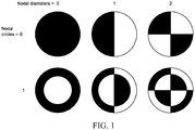
- Figure 1 shows six radial modes for fluidic pressure oscillations in a cylindrical cavity.
- the black regions of the mode shapes shown in Figure 1 represent regions of pressure difference (relative to the mean cavity pressure) having one sign, while the white regions represent pressure difference having the opposite sign.
- Figure 1 represents the pressure distribution in the cavity at a point in time: in operation the signs of the pressure differences will oscillate from positive to negative.
- the term 'radial mode' is used herein to describe the spatial profile of a pressure oscillation in the plane of the end walls of the cavity having little or no variation perpendicular to the end walls. This phrase is intended to apply to modes in both circular and near-circular cavities, including elliptical cavities. As the deviation from a circular end wall becomes more pronounced, so will the mode shape deviate from what is shown in Figure 1 .
- Radial modes of a cavity of circular cross section are characterised by the number of nodal diameters, j, and nodal circles, k, within each mode shape.
- a nodal diameter is a line that bisects the cavity along which there is little or no change in the pressure of the fluid in the cavity.
- a nodal circle is a circular line at constant cavity radius along which there is little or no change in the pressure of the fluid in the cavity.
- nodal diameter is intended to include not only a true diameter, i.e. passing through the centre of a cavity of circular cross section, but also similar paths, straight or curved, that start at one point on the perimeter of the cavity and finish at a second point along which there is no change in the pressure.
- nodal circle as used herein is similarly intended to include other substantially circular paths, such as ellipses.
- Modes with one or more nodal diameters have multiple point-antinodes which are favourable positions for the location of valved apertures.
- This cross section shows two point-antinodes at -0.35 a and +0.35 a respectively, where a is the cavity radius.
- the orientation with respect to the cavity of of modes where j > 1 is not fixed by the geometry of the cavity. This would make disposal of valves at point-antinodes problematic as the locations of these antinodes could not be predicted.
- the present invention solves this problem by designing the pump in such a way as to break the axial symmetry of these modes, thereby fixing the positions of the point-antinodes. This allows valved apertures to be disposed in predetermined locations at which pressure antinodes will be formed in operation, thereby enabling the improvements in pneumatic performance discussed above. Furthermore, because the size and shape of each point-antinode may be similar, the design of all of the valves may be the same, reducing costs in manufacture.
- the resonant frequency of a radial mode of a pressure oscillation in a given cavity increases with the number of nodal diameters of that mode, and decreases with increasing cavity radius. These two factors may be balanced such that a larger cavity can be used while maintaining the frequency of operation of the pump above that which is audible to humans. This is advantageous as larger cavities can enable greater pneumatic performance without significantly increasing the cost of manufacture. Increasing pneumatic performance while maintaining cost increases the range of commercial applications viable with this pump.
- the present invention may be described as possessing a substantially disk shaped cavity.
- the pump In operation the pump generates radial acoustic pressure oscillations.
- the cavity radius a is greater than 1.7 times the height h of the cavity, i.e. a h > 1.7
- One method of breaking the axial symmetry of the pressure oscillations and thereby fixing the positions of the point-antinodes is to drive the oscillations in the cavity with an actuator that generates axially asymmetric motion. If the mode shape of an axially asymmetric displacement oscillation of the actuator substantially matches the mode shape of an axially asymmetric pressure oscillation in the cavity then this pressure oscillation will be excited with its orientation in the plane of the cavity fixed by the asymmetry of the actuator. By aligning the orientation of the actuator to the cavity during manufacture, the positions of the pressure point-antinodes, and thus the preferable locations of the valved apertures, are also fixed.
- An actuator capable of generating axially asymmetric motion must itself have some feature of axial asymmetry. That is, there is some variation in the structure of the actuator along at least one path described by a circle that lies in the plane of the actuator and is centred on the axis normal to and passing though the centre of the end walls of the cavity.
- axial asymmetry may be embodied in the material(s) that make up the actuator (including any isolator as defined in PCT/GB 09/50613 ), any active elements such as piezoelectric materials (including state of polarisation), or any conductive materials deposited on the actuator as electrodes.
- an actuator whose active element is a disc of piezoelectric material drives the oscillatory motion of an end wall.
- axial asymmetry in the driving oscillation is introduced by the application of voltage to the piezoelectric disc via axially asymmetric electrodes. These electrodes are patterned to drive axially asymmetric oscillatory motion in the end wall and thereby generate an axially asymmetric pressure oscillation in the cavity. This approach may define the location of the point-antinodes without substantially increasing the cost of manufacture of the actuator.
- Preferred embodiments of pumps with axially asymmetric patterned electrodes are shown in Figures 4 , 5 and 6 .
- axial asymmetry is introduced by the pattern of polarisation of the piezoelectric disc.
- the polarisation of a piezoelectric material is a physical property that governs the material's response to an applied electric field. A material polarised in one direction may expand in that direction under an applied electric field; an oppositely polarised material would contract under the same conditions. Inducing axially asymmetric polarisation in an actuator can enable axially asymmetric displacement of the actuator in operation.
- a preferred embodiment of a pump having an axially asymmetric polarised piezoelectric disc is shown in Figure 7 .
- the axial asymmetry of the displacement oscillation of the actuator is generated by the axially asymmetric placement of one or more discrete piezoelectric elements.
- these piezoelectric elements are positioned such that there is substantial mode-shape matching between the displacement oscillation generated in the actuator and some part of an axially asymmetric mode of the pressure oscillation generated in the fluid in the cavity.
- Preferred embodiments of pumps with actuators with axially asymmetric placement of piezoelectric elements are shown in Figure 8 .
- a further method of defining the antinodal positions is by selecting a cavity shape that does not show axial symmetry.
- a preferable arrangement would be to construct the cavity with elliptical end walls.
- Such a cavity shows radial pressure oscillation modes broadly similar to those observed in a cavity with circular end walls, with increased distortion to the mode shapes occurring at higher values of eccentricity.
- the angular orientations of pressure modes are fixed relative to the cavity.
- the nodal diameter can be either parallel or perpendicular to the major axis of the ellipse depending on which one of two distinct modes is excited. These two modes in question have differing resonant frequencies so can be excited selectively. Therefore the axial asymmetry of the cavity defines the position of the point-antinodes relative to the cavity enabling facile placement of apertures and valves at these positions. This is distinct from the case of a cavity having circular end walls where only the actuator can define the orientation of the axially asymmetric pressure oscillation.
- An elliptical cavity has the benefit that it may not be necessary to align the actuator with the cavity in production.
- the pressure oscillations are generated using an elliptical actuator.
- This actuator could be an elliptical piezoelectric device. Such a device could generate a displacement oscillation that would produce a mode shape that matches the desired mode shape of the cavity.
- pressure oscillations are generated with a circular or semi circular actuator coupled to the elliptical cavity by a compliant membrane of the type disclosed in PCT/GB 09/50613 .
- this actuator would be a circular or semicircular piezoelectric device. This has the commercial benefit that these devices are inexpensive compared to more unusual geometries such as ellipses. This would have the disadvantage of imperfect mode-shape matching between the circular actuator and the elliptical cavity.
- An advantage of using an elliptical cavity over a circular cavity is an increase in the separation of the point-antinodes. This may simplify the manufacture and assembly of the valves and pump.
- FIG 4 shows a schematic representation of a pump 10 according to the present invention.
- a cavity 11 is defined by end walls 12 and 13, and a side wall 14.
- the cavity is substantially circular in cross section as drawn, but other suitable shapes such as elliptical could be used.
- the cavity 11 is provided with one or more nodal air inlets 15, which in this example are shown as unvalved. There are also two valved air outlets 16 located at point-antinodes.
- the first end wall 12 is partly defined by the lower surface of a disc 17 attached to the side wall 14 via a flexible membrane 30, this flexible membrane forming the remainder of the first end wall.
- the side wall 14 and the second end wall 13 are defined by a single part, the pump body 18.
- the pump body may be formed from any suitable rigid material including metal, ceramic, glass, or plastic, and in a preferred embodiment is formed from injection-moulded plastic.
- air is drawn into the pump through air inlet(s) 15 and is pumped out through valved outlets 16.
- valves 16 may be reversed such that they become air inlets and the air is pumped out through nodal air outlet(s) 15.
- the actuator comprises a piezoelectric disc 20 attached to a disc 17.
- the actuator When an appropriate electrical drive is applied, the actuator is caused to vibrate in a direction substantially perpendicular to the plane of the cavity.
- Electrical drive is applied by two separate conductive electrodes 21 and 22 and electrical connection to the disc 17 which is electrically conductive in this embodiment.
- This electrode arrangement generates axially asymmetric displacement oscillations in the actuator, which in turn generate axially asymmetric pressure oscillations within the fluid in the cavity.
- Figure 4B shows the displacement profile of the driven wall 12 of the cavity along a line bisecting the cavity and perpendicular to the nodal diameter of the oscillation of the wall.
- the solid curved line and arrows indicate the wall displacement at one point in time, and the dashed curved line its displacement one half-cycle later. Note that the displacements as drawn in this figure and the other figures are exaggerated.
- the mode shape of the displacement of the actuator is also axially asymmetric.
- Figure 4C shows the pressure oscillation profile for the cavity shown in Figure 4A along a line bisecting the cavity and perpendicular to the nodal diameter of the oscillation.
- the solid curved line and arrows indicate the pressure at one point in time, and the dashed curved line the pressure one half-cycle later.
- This oscillation has two point-antinodes at r ⁇ -0.35 a and r ⁇ 0 . 35 a.
- the two valved apertures 16 are disposed at these positions.
- Figures 4B and 4C show the modes of actuator displacement and pressure oscillation that are typically employed in the operation of the pump of Figure 4A , and thereby illustrate an important aspect of the present invention: by patterning the electrodes to excite a particular displacement oscillation in the end wall 12 whose mode shape is well matched to an axially asymmetric mode shape of the cavity that possesses one or more nodal diameter, a pressure oscillation with multiple point anti-nodes can be efficiently generated. Furthermore, the patterning of the electrodes defines the orientation of the pressure oscillation with respect to the cavity, fixing the position of the point-antinodes. This allows the disposition of multiple valves within apertures in the cavity enabling a pump with greater pneumatic performance.
- This embodiment of the present invention therefore enables good mode-shape matching to be obtained between actuator oscillation and an axially asymmetric pressure oscillation in the cavity.
- the resulting pump may deliver greater pneumatic performance without significantly increased cost.
- FIG. 5 shows a schematic representation of a pump similar in design to that of Figure 4 , but differing in its arrangement of inlets and outlets.
- the pump presented in Figure 4 possesses two valved outlets 16 operating in parallel. In that embodiment air is pumped from nodal inlet(s) 15 to valved outlets 16.
- the pump presented in Figure 5 has a valved inlet 23 and a valved outlet 24. As in the embodiment described in Figure 4 both valved apertures are disposed at point anti-nodes of the pressure oscillation in the cavity; however, there are no nodal apertures in the embodiment presented in Figure 5 .
- a pump having this series arrangement of valved apertures is capable of higher pressures than the pump presented in Figure 4 , at the cost of reduced flow rate of fluid through the pump.
- Figure 6 shows two embodiments of the present invention in which four point-antinodes are generated in the fluid oscillation in the cavity.
- Figure 6B shows a plan view schematic representation of a pump that also generates the pressure oscillation shown in Figure 6C but using an alternative electrode configuration. Here a single electrode 27 replaces two of the common phase electrodes 26 in the design disclosed in Figure 6A .
- Figure 6C also shows the approximate positions of the point antinodes 28 of the pressure oscillation and hence the preferred valved aperture positions.
- Figure 7 shows a pump wherein different regions of the piezoelectric disc are oppositely polarised to introduce axial asymmetry into the motion of the actuator.
- Figure 7A shows the displacement profile of the driven wall 12 of the cavity along a line bisecting the cavity and perpendicular to the nodal diameter of the oscillation of the wall.
- the solid curved line and arrows indicate the wall displacement at one point in time, and the dashed curved line its position one half-cycle later.
- the piezoelectric disc is divided into two regions of opposite polarisation 29 and 31.
- Figure 7B shows a plan schematic view that illustrates the extent of these regions of opposite polarisation.
- the mode shape of the displacement of the actuator is also axially asymmetric.
- the mode shape generated is shown in Figure 7C , along with the approximate positions of the point antinodes 28 of the pressure oscillation and hence the most preferred valved aperture positions.
- generating axially asymmetric actuator motion by patterning the polarisation of the piezoelectric disc allows the use of an axially symmetric electrode for the pump.
- the polarisation could be applied during manufacture of the piezoelectric disc using a temporary axially asymmetric electrode. This has advantages for fabrication of the pump as it simplifies the electrical connections to the actuator.
- Figure 8 discloses a pump wherein the actuator is coupled to a piezoelectric element which extends over a region which is not axially symmetric with the cavity.
- Figure 8A shows the displacement profile of the driven wall 12 of the cavity along a line bisecting the cavity and perpendicular to the nodal diameter of the oscillation of the wall.
- the solid curved line and arrows indicate the wall displacement at one point in time, and the dashed curved line its position one half cycle later.
- This embodiment has the advantage of reducing the amount of piezoelectric material required to fabricate a pump operating on the principle of axially asymmetric pressure oscillation thus reducing the cost of said pump. This may be particularly suited to a pump where high pressure or flow was required, but efficiency was of secondary importance.
- Figure 9 discloses several different configurations of electrode(s) and piezoelectric disc suitable for generating axially asymmetric actuator motion.
- Figure 9A shows a cross section through an actuator comprising two top electrodes 33 34 driven out of phase with one another and a bottom electrode 36 connected to ground sandwiching a piezoelectric disc with a single polarisation direction 35.
- the electric field marked on Figure 9 by arrows, and the direction of polarisation will alternate between being parallel and anti-parallel to one and other. Due to the phase difference between the drive voltages applied to the two top electrodes, when one half is parallel, the other half will be anti-parallel. The motion induced will thus be opposite in each half of the actuator, breaking axial symmetry.
- Figure 9B shows an alternative electrode configuration.
- top electrodes are connected to an alternating voltage supply 37 and ground 38 respectively.
- the bottom electrode 39 acts a common electrode and the two halves of the actuator are analogous to two capacitors in series.
- the operating mechanism is otherwise the same as that outlined above; however, this configuration allows connections to be made to the top surface of the actuator only which may be beneficial to production or reduce cost. The amplitude of the voltage required with this configuration is increased for a given actuator motion.
- Figure 9C shows a third design of actuator.
- the piezoelectric disc is bisected into two regions of opposite polarisation 41 42.
- the piezoelectric disc is sandwiched between a single top electrode 40 connected to an alternating voltage and a bottom electrode connected to ground 42.
- the two halves of the actuator experience the same electric field; yet have opposite polarisations, generating the same axial asymmetry in motion observed in the actuator designs disclosed in Figure 9A and Figure 9B .
Landscapes
- Engineering & Computer Science (AREA)
- Mechanical Engineering (AREA)
- General Engineering & Computer Science (AREA)
- Reciprocating Pumps (AREA)
Description
- The illustrative embodiments of the invention relate generally to a pump for fluid and, more specifically, to a pump having a substantially disc-shaped cavity with substantially circular end walls and a side wall and a valve for controlling the flow of fluid through the pump.
- The generation of high amplitude pressure oscillations in closed cavities has received significant attention in the field of pump type compressors. Recent developments have allowed the generation of pressure waves with higher amplitudes than previously thought possible.
- It is known to use acoustic resonance to achieve fluid pumping from defined inlets and outlets. This can be achieved using a cylindrical cavity with an actuator at one end, which drives an acoustic standing wave. In such a cylindrical cavity, the acoustic pressure wave has limited amplitude. Varying cross-section cavities, such as cone, horn-cone and bulb have been used to achieve high amplitude pressure oscillations thereby significantly increasing the pumping effect. In such high amplitude waves the non-linear mechanisms of energy dissipation have been suppressed. However, high amplitude acoustic resonance has not been employed within disc-shaped cavities in which radial pressure oscillations are excited until recently. Patent applications
WO2006/111755 ,WO2009/112866 ,PCT/GB2009/050613 PCT/GB2009/050615 - The pump disclosed in
WO2009/112866 has a substantially cylindrical cavity comprising a side wall closed at each end by an end wall. The pump also comprises an actuator that drives one or both of the end walls to oscillate in a direction substantially perpendicular to the surface of the plane of the end walls. The spatial profile of the motion of the driven end wall is described inWO2009/112866 as being matched to the spatial profile of the fluid pressure oscillations within the cavity, a state described therein as mode-shape matching. When the pump is mode-shape matched, work done by the actuator on the fluid in the cavity adds constructively across the driven end wall surface, thereby enhancing the amplitude of the pressure oscillation in the cavity and delivering improved pump efficiency. In a pump which is not mode-shape matched, there may be areas of the end wall wherein the work done by the end wall on the fluid reduces rather than enhances the amplitude of the fluid pressure oscillation in the fluid within the cavity. Thus, the useful work done by the actuator on the fluid is reduced and the pump becomes less efficient. The efficiency of a mode-shape matched pump may be dependent upon the interface between the driven end wall and the side wall. It is desirable to maintain the efficiency of such a pump by structuring this interface so that it does not significantly decrease or dampen the motion of the driven end wall thereby mitigating any reduction in the amplitude of the fluid pressure oscillations within the cavity. - Mode-shape matching the spatial profile of the displacement of the driven end wall to the spatial profile of the pressure oscillations of the fluid is preferable for efficient operation of the fluidic pump disclosed in
WO2006/111755 .Figures 3A and 3B ofWO2006/111755 show the spatial profiles, referred to herein as modes, of the driven end wall for preferred embodiments of such a pump.Figure 3A ofWO2006/111755 shows an axisymmetric mode. Herein, axisymmetric is taken to mean having infinite order rotational symmetry, or equivalently being cylindrically symmetric, about the axis normal to and passing through the centre of the end walls of the cavity. For objects which do not have an obvious geometric centre, the term centre herein refers to the centre of mass of the object. Any object, group of objects or mode of oscillation which does not have this property is referred to herein as axially asymmetric. The axisymmetric mode shown inFigure 3A ofWO2006/111755 has maximum amplitude at the centre decreasing continuously to a minimum at the edge. -
Figure 3B ofWO2006/111755 shows an axisymmetric mode where the displacement of the end wall is described by a Bessel function as further described therein. In this case, as the centre of the drivenend wall 12 moves away from theopposite end wall 13, the outer portion of the drivenend wall 12 is caused to move towards theopposite end wall 13. The modes of oscillation of the end walls in both of the above cases are matched to natural modes of acoustic oscillation of the cavity. Both of these modes show an antinode in the pressure oscillation localised at a single point, herein described as a point-antinode, at the centre of the cavity. The large pressure amplitude at this position makes it an ideal position for an aperture into the cavity with a valve, herein referred to as a valved aperture, operating as an inlet or outlet. - It is desirable to increase the pneumatic output of such a pump by increasing its pressure or flow capability. This would increase the range of applications that the pump is suitable for. The frequency of the fundamental-mode pressure oscillation of the cavity decreases with increasing area of the cavity end walls so the pump's performance cannot be improved simply by increasing its size without compromising the pump's valuable property of silence in the frequency range audible to humans.
- One solution is to increase the diameter of the central valved
aperture 16 of a pump of the type shown inFigure 1 ofWO2006/111755 while maintaining thecavity 11 size. This can enable a reduction in the fluidic flow resistance of the valve, delivering improved performance. However, the magnitude of the pressure oscillation can decrease rapidly with distance from the centre of the cavity, reducing the effectiveness of this solution. - A second solution is to mount two
central valves 316 and 16, one in eachend wall Figure 9A ofGB1001740.8 - A third solution, applicable to the pump design described above wherein the pressure oscillation has the form of an axisymmetric Bessel function, is to mount a second valve at the outer edge of the cavity (at which in operation there exists a circular pressure antinode). In practise this design has several disadvantages. Firstly, due to the radial nature of the pressure oscillation this circular antinode has a lower pressure amplitude than the central point-antinode and therefore the rectified pressure delivered by the valve is lower. Secondly, a different design of valve may be required in order to best match the shape of the pressure antinode at the edge of the cavity. A second valve design could increase manufacturing costs. Finally, a more complex manifold may be required to channel the flow of fluid into or out of the pump.
-
US 6227824 discloses a fluid pump having a pump body and a displacer which define a pump chamber. The pump operates in a disc pump displacement mode in which the motion of the displacer substantially changes the volume of the cavity during operation. -
EP 1952992 discloses a liquid transport apparatus which is a displacement pump operating by way of a driver electrode deforming a vibration plate towards a base member, thereby reducing the volume of a pressure chamber. -
US 2003/0124006 discloses a displacement pump having a pumping cavity located within a housing, whereby deformation of the housing creates volume changes in the cavity. -
US 6079214 discloses a standing wave pump in which a standing compression wave is produced by a pair of dielectrically opposing transducers such that the standing waves generated in the cavity are planar compression waves, alternatively known as longitudinal or organ mode waves. -
WO 2010/139918 discloses a pump having a substantially cylindrical shape and defining a cavity formed by a side wall closed at both ends by end walls wherein the cavity contains a fluid is disclosed. The pump further comprises an actuator operatively associated with at least one of the end walls to cause an oscillatory motion of the driven end wall to generate displacement oscillations of the driven end wall within the cavity. The pump further comprises an isolator operatively associated with a peripheral portion of the driven end wall to reduce dampening of the displacement oscillations. The pump further comprises a valve for controlling the flow of fluid through the valve. The valve has first and second plates with offsetting apertures and a sidewall disposed between the plates around the perimeter of the plates to form a cavity in fluid communication with the apertures. The valve further comprises a flap disposed and moveable between the first and second plates and having apertures substantially offset from the apertures of one plate and substantially aligned with the apertures of the other plate. The flap is motivated between the two plates in response to a change in direction of the differential pressure of fluid across the valve. - In the present invention the pump cavity is designed and driven such that a plurality of high-amplitude pressure point-antinodes is generated within the cavity, providing multiple favourable positions for valved apertures. In this manner the limitations of the prior art are overcome.
- To provide increased flow relative to the pumps described in the prior art, two or more of these valved apertures may be configured to act in parallel (i.e. all inlets or all outlets) with unvalved apertures located at pressure nodes acting as an outlets or inlets respectively. To provide increased pressure difference the valved apertures may be configured to act in series, with both inlets and outlets being valved.
- It will be evident to one skilled in the art that the presence of a plurality of high-amplitude pressure point-antinodes facilitates improvement of the pneumatic performance of the pump, as desired.
- Therefore, according to the present invention, there is provided a fluid pump comprising: a side wall closed at each end by an end wall forming a substantially circular cavity for, in use, containing a fluid; one or more actuators each operatively associated with one or more of the end walls to cause an oscillatory motion of the associated end wall(s) whereby, in use, these axial oscillations of the end wall(s) drive radial oscillations of the fluid pressure in the cavity; two or more apertures into the cavity; a valve disposed in at least one of the apertures; wherein the actuator(s) is axially asymmetric such that, in use, a pressure oscillation with at least one nodal diameter is generated within the cavity, wherein the ratio of the radius of the cavity to the height of the cavity is greater than 1.7.
- The actuator may include axially asymmetric features and also may include a piezoelectric layer.
- The axial asymmetry of the actuator may be defined by sections of the piezoelectric layer having different polarity.
- The actuator preferably includes at least two electrodes. The axial asymmetry may be defined by separate electrodes and/or the absence of an electrode. At least one of the electrodes may be non-coaxial relative to the actuator. By "non coaxial", we mean that the longitudinal axis of the electrode(s) is different to that of the actuator itself.
- Additionally or alternatively, a plurality of electrodes may be provided in a regular pattern which is non-coaxial relative to the actuator.
- The actuator may include a piezoelectric layer which is non-coaxial relative to the cavity.
- The pump may further include a voltage generator for generating one or more drive signals for supply to the actuator. The drive signal(s) generated by the electrical drive circuit may cause generation of non-axisymmetric motion of the actuator.
- The actuator may contain at least one elliptical element, which may be a piezoelectric element or may be an electrode or both.
- The actuator may cause a pressure oscillation with a plurality of nodal diameters to be generated.
- The end wall motion is preferably mode-shape matched to the pressure oscillations in the cavity.
- The frequency of the oscillatory motion is preferably within 20% of a resonant frequency of the substantially radial pressure oscillations in the cavity.
- In use, the frequency of the oscillatory motion is preferably equal to a resonant frequency of the substantially radial pressure oscillations in the cavity.
- The cavity of the pump is preferably substantially circular or elliptical.
- The pump may further contain at least two apertures including at least one inlet aperture and at least one outlet aperture. In use, the pressure oscillations of the fluid in the cavity preferably cause fluid to flow from one or more of the inlet apertures to one or more of the outlet apertures.
- The frequency of pressure oscillations in the cavity is preferably greater than 500 Hz.
- The frequency of radial pressure oscillations in the cavity is more preferably greater than 19,000 Hz.
- The ratio of the radius of the cavity (a) to the height of the side wall (h) is preferably greater than 1.7.
- A pair of pumps may be provided, wherein the two pump cavities are separated by a common end wall. The common cavity end wall may be formed by an actuator.
- Other objects, features, and advantages of the illustrative embodiments are described herein and will become apparent with reference to the drawings and detailed description that follow.
-
-
Figure 1 shows the sign of the radial mode shapes of pressure oscillations in a cylindrical cavity. -
Figure 2 shows a plot of the relative pressure along a line perpendicular to the nodal diameter of a pressure oscillation with radial mode j =1, k =1 in a cylindrical cavity. -
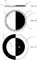
Figure 3 shows the sign of the radial mode shapes of pressure oscillations in a cylindroid cavity of elliptical cross section. -
Figure 4 shows a schematic cross-section view of a first pump according to an illustrative embodiment with two valved outlets operating in parallel and a nodal inlet, a graph of the displacement oscillations of the driven end wall of the pump, a graph of the pressure oscillations within the cavity of the pump and a schematic plan view of the pump. -
Figure 5 shows a schematic cross-section view of a second pump according to an illustrative embodiment with two valved apertures operating in series, a graph of the displacement oscillations of the driven end wall of the pump, a graph of the pressure oscillations within the cavity of the pump and a schematic plan view of the pump. -
Figure 6 shows a schematic plan view of a third pump according to an illustrative embodiment with four valved apertures and four separate electrodes, a schematic plan view of a fourth pump according to an illustrative embodiment with four valved apertures and an alternative electrode configuration, and a representation of the mode shape of the resultant pressure oscillation in the cavity of the two above pumps with the preferred positions of valved apertures marked. -
Figure 7 shows a graph of the displacement oscillations of the driven end wall according to a fifth embodiment, a schematic plan view of the pump showing the polarisation of the piezoelectric disc, and a representation of the mode shape of the resultant pressure oscillation in the cavity of the pump with the preferred positions of valved apertures marked. -
Figure 8 shows a graph of the displacement oscillations of the driven end wall according to a sixth embodiment, a schematic plan view of the pump showing the extent of the piezoelectric disc, and a representation of the mode shape of the resultant pressure oscillation in the cavity of the pump with the preferred positions of valved apertures marked. -
Figure 9 discloses several different configurations of electrode(s) and piezoelectric disc suitable for generating axially asymmetric actuator motion. -
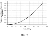
Figure 10 shows a plot of the difference in resonant frequency between the parallel and perpendicular orientations of the mode j =1, k =1 in a cylindroid cavity with increasing eccentricity. - In the following detailed description of several illustrative embodiments, reference is made to the accompanying drawings that form a part hereof, and in which is shown by way of illustration specific preferred embodiments in which the invention may be practiced. These embodiments are described in sufficient detail to enable those skilled in the art to practice the invention, and it is understood that other embodiments may be utilized and that logical structural, mechanical, electrical, and chemical changes may be made without departing from the spirit or scope of the invention. To avoid detail not necessary to enable those skilled in the art to practice the embodiments described herein, the description may omit certain information known to those skilled in the art. The following detailed description is, therefore, not to be taken in a limiting sense, and the scope of the illustrative embodiments are defined only by the appended claims.
-
Figure 1 shows six radial modes for fluidic pressure oscillations in a cylindrical cavity. The black regions of the mode shapes shown inFigure 1 represent regions of pressure difference (relative to the mean cavity pressure) having one sign, while the white regions represent pressure difference having the opposite sign.Figure 1 represents the pressure distribution in the cavity at a point in time: in operation the signs of the pressure differences will oscillate from positive to negative. - Note that the term 'radial mode' is used herein to describe the spatial profile of a pressure oscillation in the plane of the end walls of the cavity having little or no variation perpendicular to the end walls. This phrase is intended to apply to modes in both circular and near-circular cavities, including elliptical cavities. As the deviation from a circular end wall becomes more pronounced, so will the mode shape deviate from what is shown in
Figure 1 . - Radial modes of a cavity of circular cross section are characterised by the number of nodal diameters, j, and nodal circles, k, within each mode shape. A nodal diameter is a line that bisects the cavity along which there is little or no change in the pressure of the fluid in the cavity. A nodal circle is a circular line at constant cavity radius along which there is little or no change in the pressure of the fluid in the cavity.
- Note that the term "nodal diameter" as used herein is intended to include not only a true diameter, i.e. passing through the centre of a cavity of circular cross section, but also similar paths, straight or curved, that start at one point on the perimeter of the cavity and finish at a second point along which there is no change in the pressure. The term "nodal circle" as used herein is similarly intended to include other substantially circular paths, such as ellipses.
- Modes with one or more nodal diameters have multiple point-antinodes which are favourable positions for the location of valved apertures. For example,
Figure 2 shows a plot of the relative pressure along a line perpendicular to the nodal diameter of a pressure oscillation with radial mode j =1, k =1 in a cylindrical cavity. The pressure oscillation along this path, p(r), approximates the form of the Bessel function:
- This cross section shows two point-antinodes at -0.35a and +0.35a respectively, where a is the cavity radius.
- For a cylindrical cavity the orientation with respect to the cavity of of modes where j > 1 is not fixed by the geometry of the cavity. This would make disposal of valves at point-antinodes problematic as the locations of these antinodes could not be predicted. The present invention solves this problem by designing the pump in such a way as to break the axial symmetry of these modes, thereby fixing the positions of the point-antinodes. This allows valved apertures to be disposed in predetermined locations at which pressure antinodes will be formed in operation, thereby enabling the improvements in pneumatic performance discussed above. Furthermore, because the size and shape of each point-antinode may be similar, the design of all of the valves may be the same, reducing costs in manufacture.
- The resonant frequency of a radial mode of a pressure oscillation in a given cavity increases with the number of nodal diameters of that mode, and decreases with increasing cavity radius. These two factors may be balanced such that a larger cavity can be used while maintaining the frequency of operation of the pump above that which is audible to humans. This is advantageous as larger cavities can enable greater pneumatic performance without significantly increasing the cost of manufacture. Increasing pneumatic performance while maintaining cost increases the range of commercial applications viable with this pump.
- The present invention, as with the pump disclosed in
WO2006/111755 , may be described as possessing a substantially disk shaped cavity. In operation the pump generates radial acoustic pressure oscillations. In particular, when the cavity radius a is greater than 1.7 times the height h of the cavity, i.e.

- To avoid inefficient operation resultant from high viscous losses in the fluid in the cavity the height of the cavity should be at least twice the thickness of the viscous boundary layer in the fluid:

where µ is the viscosity of the fluid, ρ is the density of the fluid, c is the speed of sound in the fluid and k1 is the wave number of the Bessel function j =1, k =1. Rearranging the above expression and substituting in appropriate values for density and viscosity,
- One method of breaking the axial symmetry of the pressure oscillations and thereby fixing the positions of the point-antinodes is to drive the oscillations in the cavity with an actuator that generates axially asymmetric motion. If the mode shape of an axially asymmetric displacement oscillation of the actuator substantially matches the mode shape of an axially asymmetric pressure oscillation in the cavity then this pressure oscillation will be excited with its orientation in the plane of the cavity fixed by the asymmetry of the actuator. By aligning the orientation of the actuator to the cavity during manufacture, the positions of the pressure point-antinodes, and thus the preferable locations of the valved apertures, are also fixed.
- An actuator capable of generating axially asymmetric motion must itself have some feature of axial asymmetry. That is, there is some variation in the structure of the actuator along at least one path described by a circle that lies in the plane of the actuator and is centred on the axis normal to and passing though the centre of the end walls of the cavity. For clarity, such axial asymmetry may be embodied in the material(s) that make up the actuator (including any isolator as defined in
PCT/GB 09/50613 - In a preferred embodiment, an actuator whose active element is a disc of piezoelectric material drives the oscillatory motion of an end wall. Because the manufacture of an axially asymmetric disc of piezoelectric material may be economically inefficient, axial asymmetry in the driving oscillation is introduced by the application of voltage to the piezoelectric disc via axially asymmetric electrodes. These electrodes are patterned to drive axially asymmetric oscillatory motion in the end wall and thereby generate an axially asymmetric pressure oscillation in the cavity. This approach may define the location of the point-antinodes without substantially increasing the cost of manufacture of the actuator. Preferred embodiments of pumps with axially asymmetric patterned electrodes are shown in
Figures 4 ,5 and6 . - In a second preferred embodiment, also including an actuator whose active element is a disc of piezoelectric material, axial asymmetry is introduced by the pattern of polarisation of the piezoelectric disc. The polarisation of a piezoelectric material is a physical property that governs the material's response to an applied electric field. A material polarised in one direction may expand in that direction under an applied electric field; an oppositely polarised material would contract under the same conditions. Inducing axially asymmetric polarisation in an actuator can enable axially asymmetric displacement of the actuator in operation. A preferred embodiment of a pump having an axially asymmetric polarised piezoelectric disc is shown in
Figure 7 . - In a third preferred embodiment the axial asymmetry of the displacement oscillation of the actuator is generated by the axially asymmetric placement of one or more discrete piezoelectric elements. In a more preferred embodiment these piezoelectric elements are positioned such that there is substantial mode-shape matching between the displacement oscillation generated in the actuator and some part of an axially asymmetric mode of the pressure oscillation generated in the fluid in the cavity. Preferred embodiments of pumps with actuators with axially asymmetric placement of piezoelectric elements are shown in
Figure 8 . - A further method of defining the antinodal positions is by selecting a cavity shape that does not show axial symmetry. A preferable arrangement would be to construct the cavity with elliptical end walls. Such a cavity shows radial pressure oscillation modes broadly similar to those observed in a cavity with circular end walls, with increased distortion to the mode shapes occurring at higher values of eccentricity. The mode j =1, k =1 for cavities with end walls of eccentricity 0.4 and 0.6 is shown in
Figure 3 . - Due to the axial asymmetry in such a cavity, the angular orientations of pressure modes are fixed relative to the cavity. For example, for the j =1, k =1 modes shown in
Figure 3 the nodal diameter can be either parallel or perpendicular to the major axis of the ellipse depending on which one of two distinct modes is excited. These two modes in question have differing resonant frequencies so can be excited selectively. Therefore the axial asymmetry of the cavity defines the position of the point-antinodes relative to the cavity enabling facile placement of apertures and valves at these positions. This is distinct from the case of a cavity having circular end walls where only the actuator can define the orientation of the axially asymmetric pressure oscillation. An elliptical cavity has the benefit that it may not be necessary to align the actuator with the cavity in production. - The difference in resonant frequency of the parallel and perpendicular orientations of the mode j =1, k =1 with eccentricity are shown in
Figure 10 . It is worth noting that for the design of a practical pump the value of the eccentricity need not be large to achieve a frequency splitting sufficient to permit facile selective excitation of one of the two orientations of the above mode, the cavity can remain substantially circular. - In one embodiment of the present invention, the pressure oscillations are generated using an elliptical actuator. This actuator could be an elliptical piezoelectric device. Such a device could generate a displacement oscillation that would produce a mode shape that matches the desired mode shape of the cavity.
- In another embodiment of the present invention pressure oscillations are generated with a circular or semi circular actuator coupled to the elliptical cavity by a compliant membrane of the type disclosed in
PCT/GB 09/50613 - An advantage of using an elliptical cavity over a circular cavity is an increase in the separation of the point-antinodes. This may simplify the manufacture and assembly of the valves and pump.
-
Figure 4 shows a schematic representation of apump 10 according to the present invention. Acavity 11 is defined byend walls side wall 14. The cavity is substantially circular in cross section as drawn, but other suitable shapes such as elliptical could be used. Thecavity 11 is provided with one or morenodal air inlets 15, which in this example are shown as unvalved. There are also twovalved air outlets 16 located at point-antinodes. Thefirst end wall 12 is partly defined by the lower surface of adisc 17 attached to theside wall 14 via aflexible membrane 30, this flexible membrane forming the remainder of the first end wall. In this case theside wall 14 and thesecond end wall 13 are defined by a single part, thepump body 18. The pump body may be formed from any suitable rigid material including metal, ceramic, glass, or plastic, and in a preferred embodiment is formed from injection-moulded plastic. In this embodiment air is drawn into the pump through air inlet(s) 15 and is pumped out throughvalved outlets 16. Other configurations are possible e.g. thevalves 16 may be reversed such that they become air inlets and the air is pumped out through nodal air outlet(s) 15. - The actuator comprises a
piezoelectric disc 20 attached to adisc 17. When an appropriate electrical drive is applied, the actuator is caused to vibrate in a direction substantially perpendicular to the plane of the cavity. Electrical drive is applied by two separateconductive electrodes disc 17 which is electrically conductive in this embodiment. This electrode arrangement generates axially asymmetric displacement oscillations in the actuator, which in turn generate axially asymmetric pressure oscillations within the fluid in the cavity. -
Figure 4B shows the displacement profile of the drivenwall 12 of the cavity along a line bisecting the cavity and perpendicular to the nodal diameter of the oscillation of the wall. The solid curved line and arrows indicate the wall displacement at one point in time, and the dashed curved line its displacement one half-cycle later. Note that the displacements as drawn in this figure and the other figures are exaggerated. Because of the axially asymmetric patterning of theelectrodes Figure 4D , the mode shape of the displacement of the actuator is also axially asymmetric. For the electrode configuration shown inFigure 4D the mode shape of the actuator closely resembles the j =1, k =1 mode shape of the cylindrical cavity. -
Figure 4C shows the pressure oscillation profile for the cavity shown inFigure 4A along a line bisecting the cavity and perpendicular to the nodal diameter of the oscillation. The solid curved line and arrows indicate the pressure at one point in time, and the dashed curved line the pressure one half-cycle later. The pressure oscillation along this path, p(r), approximates the form of the Bessel function:
- This oscillation has two point-antinodes at r ≈ -0.35a and r ≈ 0.35a. The two
valved apertures 16 are disposed at these positions. -
Figures 4B and 4C show the modes of actuator displacement and pressure oscillation that are typically employed in the operation of the pump ofFigure 4A , and thereby illustrate an important aspect of the present invention: by patterning the electrodes to excite a particular displacement oscillation in theend wall 12 whose mode shape is well matched to an axially asymmetric mode shape of the cavity that possesses one or more nodal diameter, a pressure oscillation with multiple point anti-nodes can be efficiently generated. Furthermore, the patterning of the electrodes defines the orientation of the pressure oscillation with respect to the cavity, fixing the position of the point-antinodes. This allows the disposition of multiple valves within apertures in the cavity enabling a pump with greater pneumatic performance. - This embodiment of the present invention therefore enables good mode-shape matching to be obtained between actuator oscillation and an axially asymmetric pressure oscillation in the cavity. The resulting pump may deliver greater pneumatic performance without significantly increased cost.
-
Figure 5 shows a schematic representation of a pump similar in design to that ofFigure 4 , but differing in its arrangement of inlets and outlets. The pump presented inFigure 4 possesses twovalved outlets 16 operating in parallel. In that embodiment air is pumped from nodal inlet(s) 15 tovalved outlets 16. The pump presented inFigure 5 has avalved inlet 23 and avalved outlet 24. As in the embodiment described inFigure 4 both valved apertures are disposed at point anti-nodes of the pressure oscillation in the cavity; however, there are no nodal apertures in the embodiment presented inFigure 5 . A pump having this series arrangement of valved apertures is capable of higher pressures than the pump presented inFigure 4 , at the cost of reduced flow rate of fluid through the pump. -
Figure 6 shows two embodiments of the present invention in which four point-antinodes are generated in the fluid oscillation in the cavity.Figure 6A shows a plan schematic view of a pump with four separate electrodes. Two electrodes electrically driven with acommon phase 25 and a further two driven 180° out of phase with the first two 26. This configuration will generate a pressure oscillation of the mode j =2, k =1 in the cavity, shown inFigure 6C , and can deliver good mode-shape matching between actuator displacement and cavity pressure.Figure 6B shows a plan view schematic representation of a pump that also generates the pressure oscillation shown inFigure 6C but using an alternative electrode configuration. Here asingle electrode 27 replaces two of thecommon phase electrodes 26 in the design disclosed inFigure 6A . This example illustrates that it is the axially asymmetric field across the piezoelectric disc that is of paramount importance for this embodiment, this field can be generated by any number of similar electrode configurations.Figure 6C also shows the approximate positions of thepoint antinodes 28 of the pressure oscillation and hence the preferred valved aperture positions. -
Figure 7 shows a pump wherein different regions of the piezoelectric disc are oppositely polarised to introduce axial asymmetry into the motion of the actuator.Figure 7A shows the displacement profile of the drivenwall 12 of the cavity along a line bisecting the cavity and perpendicular to the nodal diameter of the oscillation of the wall. The solid curved line and arrows indicate the wall displacement at one point in time, and the dashed curved line its position one half-cycle later. - The piezoelectric disc is divided into two regions of
opposite polarisation Figure 7B shows a plan schematic view that illustrates the extent of these regions of opposite polarisation. - Because of the axially asymmetric polarisation of the piezoelectric disc, the mode shape of the displacement of the actuator is also axially asymmetric. For the polarisation configuration shown in
Figure 7B the mode shape of the actuator closely resembles the j =1, k =1 mode shape of the cylindrical cavity. This leads to the generation of a pressure oscillation of this mode in the cavity and good mode-shape matching between the two. The mode shape generated is shown inFigure 7C , along with the approximate positions of thepoint antinodes 28 of the pressure oscillation and hence the most preferred valved aperture positions. - It is worth noting that generating axially asymmetric actuator motion by patterning the polarisation of the piezoelectric disc allows the use of an axially symmetric electrode for the pump. The polarisation could be applied during manufacture of the piezoelectric disc using a temporary axially asymmetric electrode. This has advantages for fabrication of the pump as it simplifies the electrical connections to the actuator.
-
Figure 8 discloses a pump wherein the actuator is coupled to a piezoelectric element which extends over a region which is not axially symmetric with the cavity.Figure 8A shows the displacement profile of the drivenwall 12 of the cavity along a line bisecting the cavity and perpendicular to the nodal diameter of the oscillation of the wall. The solid curved line and arrows indicate the wall displacement at one point in time, and the dashed curved line its position one half cycle later. -
Figure 8B shows a plan schematic view that illustrates the extent of thepiezoelectric disc 32. Because of the axially asymmetric extent of the piezoelectric disc, the mode shape of the displacement of the actuator is also axially asymmetric. For the configuration shown inFigure 8B the mode shape of the actuator resembles the j =1, k =1 mode shape of the cylindrical cavity. This leads to the generation of a pressure oscillation of this mode in the cavity and good mode-shape matching between the two. The mode shape generated is shown inFigure 8C , along with the approximate positions of thepoint antinodes 28 of the pressure oscillation and hence the most preferred valved aperture positions. - This embodiment has the advantage of reducing the amount of piezoelectric material required to fabricate a pump operating on the principle of axially asymmetric pressure oscillation thus reducing the cost of said pump. This may be particularly suited to a pump where high pressure or flow was required, but efficiency was of secondary importance.
-
Figure 9 discloses several different configurations of electrode(s) and piezoelectric disc suitable for generating axially asymmetric actuator motion.Figure 9A shows a cross section through an actuator comprising twotop electrodes 33 34 driven out of phase with one another and abottom electrode 36 connected to ground sandwiching a piezoelectric disc with asingle polarisation direction 35. In operation the electric field, marked onFigure 9 by arrows, and the direction of polarisation will alternate between being parallel and anti-parallel to one and other. Due to the phase difference between the drive voltages applied to the two top electrodes, when one half is parallel, the other half will be anti-parallel. The motion induced will thus be opposite in each half of the actuator, breaking axial symmetry.Figure 9B shows an alternative electrode configuration. Here the top electrodes are connected to an alternatingvoltage supply 37 andground 38 respectively. In this configuration thebottom electrode 39 acts a common electrode and the two halves of the actuator are analogous to two capacitors in series. The operating mechanism is otherwise the same as that outlined above; however, this configuration allows connections to be made to the top surface of the actuator only which may be beneficial to production or reduce cost. The amplitude of the voltage required with this configuration is increased for a given actuator motion. -
Figure 9C shows a third design of actuator. Here, as disclosed inFigure 7 , the piezoelectric disc is bisected into two regions ofopposite polarisation 41 42. In this case the piezoelectric disc is sandwiched between a singletop electrode 40 connected to an alternating voltage and a bottom electrode connected to ground 42. The two halves of the actuator experience the same electric field; yet have opposite polarisations, generating the same axial asymmetry in motion observed in the actuator designs disclosed inFigure 9A and Figure 9B .
Claims (15)
- A pump (10) comprising:a side wall (14) closed at each end by an end wall (12, 13) forming a substantially circular cavity (11) for, in use, containing a fluid;one or more actuators (17, 20) each operatively associated with one or more of the end walls to cause an oscillatory motion of the associated end wall(s) whereby, in use, these axial oscillations of the end wall(s) drive substantially radial oscillations of the fluid pressure in the cavity;two or more apertures (15) in the cavity;a valve (16) disposed in at least one of the apertures;wherein the ratio of the radius of the cavity (a) to the height of the side wall (h) is greater than 1.7;characterised in that the actuator(s) is axially asymmetric such that, in use, a pressure oscillation with at least one nodal diameter is generated within the cavity.
- A pump (10) according to claim 1, wherein the actuator (17, 20) includes axially asymmetric features.
- A pump (10) according to claim 1, wherein the actuator includes a piezoelectric layer (20).
- A pump (10) according to claim 3, wherein the axial asymmetry is defined by sections of the piezoelectric layer (20) having different polarisation.
- A pump (10) according to any one of claims 1 to 3, wherein the actuator (17, 20) includes at least two electrodes (21, 22).
- A pump (10) according to claim 5, wherein the axial asymmetry is defined by separate electrodes and/or the absence of an electrode.
- A pump (10) according to claim 5, wherein at least one of the electrodes is non-coaxial relative to the actuator.
- A pump (10) according to claim 5, wherein a plurality of electrodes (21, 22) are provided in a regular pattern which is non-coaxial relative to the actuator.
- A pump (10) according to claim 1, wherein the actuator includes a piezoelectric layer (20) which is non-coaxial relative to the cavity (11).
- A pump (10) according to any one of the preceding claims, further comprising an electrical drive circuit for generating one or more drive signals for supply to the actuator.
- A pump (10) according to claim 10, wherein the drive signal(s) cause generation of axially asymmetric motion of the actuator (17, 20).
- A pump (10) according to any one of the preceding claims, wherein the actuator (17, 20) contains at least one elliptical element.
- A pump (10) according to any one of the preceding claims, wherein, in use, the actuator (17, 20) causes a pressure oscillation with a plurality of nodal diameters to be generated.
- A pump (10) according to any one of the preceding claims, wherein the end wall motion is mode-shape matched to the pressure oscillations in the cavity.
- A pump (10) according to any one of the preceding claims, wherein the radius of the cavity (a) and the height of the side wall (h) satisfy the relationship

Applications Claiming Priority (2)
| Application Number | Priority Date | Filing Date | Title |
|---|---|---|---|
| GBGB1101870.2A GB201101870D0 (en) | 2011-02-03 | 2011-02-03 | Pump |
| PCT/GB2012/050227 WO2012104648A1 (en) | 2011-02-03 | 2012-02-03 | Pump |
Publications (2)
| Publication Number | Publication Date |
|---|---|
| EP2670982A1 EP2670982A1 (en) | 2013-12-11 |
| EP2670982B1 true EP2670982B1 (en) | 2020-08-26 |
Family
ID=43836153
Family Applications (1)
| Application Number | Title | Priority Date | Filing Date |
|---|---|---|---|
| EP12703335.5A Active EP2670982B1 (en) | 2011-02-03 | 2012-02-03 | Pump |
Country Status (4)
| Country | Link |
|---|---|
| US (1) | US10975855B2 (en) |
| EP (1) | EP2670982B1 (en) |
| GB (1) | GB201101870D0 (en) |
| WO (1) | WO2012104648A1 (en) |
Families Citing this family (29)
| Publication number | Priority date | Publication date | Assignee | Title |
|---|---|---|---|---|
| GB2513884B (en) | 2013-05-08 | 2015-06-17 | Univ Bristol | Method and apparatus for producing an acoustic field |
| US9612658B2 (en) | 2014-01-07 | 2017-04-04 | Ultrahaptics Ip Ltd | Method and apparatus for providing tactile sensations |
| WO2015133283A1 (en) * | 2014-03-07 | 2015-09-11 | 株式会社村田製作所 | Blower |
| GB2530036A (en) | 2014-09-09 | 2016-03-16 | Ultrahaptics Ltd | Method and apparatus for modulating haptic feedback |
| US10983092B2 (en) * | 2014-12-11 | 2021-04-20 | The Technology Partnership Plc | Acoustic sensor |
| US10101811B2 (en) | 2015-02-20 | 2018-10-16 | Ultrahaptics Ip Ltd. | Algorithm improvements in a haptic system |
| WO2016132144A1 (en) | 2015-02-20 | 2016-08-25 | Ultrahaptics Ip Limited | Perceptions in a haptic system |
| US10818162B2 (en) | 2015-07-16 | 2020-10-27 | Ultrahaptics Ip Ltd | Calibration techniques in haptic systems |
| US11189140B2 (en) | 2016-01-05 | 2021-11-30 | Ultrahaptics Ip Ltd | Calibration and detection techniques in haptic systems |
| US10268275B2 (en) | 2016-08-03 | 2019-04-23 | Ultrahaptics Ip Ltd | Three-dimensional perceptions in haptic systems |
| US10943578B2 (en) | 2016-12-13 | 2021-03-09 | Ultrahaptics Ip Ltd | Driving techniques for phased-array systems |
| GB2561613B (en) * | 2017-04-21 | 2019-05-08 | The Technology Partnership Plc | Acoustic Sensor |
| US11531395B2 (en) | 2017-11-26 | 2022-12-20 | Ultrahaptics Ip Ltd | Haptic effects from focused acoustic fields |
| WO2019122912A1 (en) | 2017-12-22 | 2019-06-27 | Ultrahaptics Limited | Tracking in haptic systems |
| US11704983B2 (en) | 2017-12-22 | 2023-07-18 | Ultrahaptics Ip Ltd | Minimizing unwanted responses in haptic systems |
| SG11202010752VA (en) | 2018-05-02 | 2020-11-27 | Ultrahaptics Ip Ltd | Blocking plate structure for improved acoustic transmission efficiency |
| US11098951B2 (en) | 2018-09-09 | 2021-08-24 | Ultrahaptics Ip Ltd | Ultrasonic-assisted liquid manipulation |
| US11378997B2 (en) | 2018-10-12 | 2022-07-05 | Ultrahaptics Ip Ltd | Variable phase and frequency pulse-width modulation technique |
| US12373033B2 (en) | 2019-01-04 | 2025-07-29 | Ultrahaptics Ip Ltd | Mid-air haptic textures |
| WO2020141330A2 (en) | 2019-01-04 | 2020-07-09 | Ultrahaptics Ip Ltd | Mid-air haptic textures |
| US11842517B2 (en) | 2019-04-12 | 2023-12-12 | Ultrahaptics Ip Ltd | Using iterative 3D-model fitting for domain adaptation of a hand-pose-estimation neural network |
| US11374586B2 (en) | 2019-10-13 | 2022-06-28 | Ultraleap Limited | Reducing harmonic distortion by dithering |
| JP7611244B2 (en) | 2019-10-13 | 2025-01-09 | ウルトラリープ リミテッド | Dynamic Capping with Virtual Microphone |
| US11169610B2 (en) | 2019-11-08 | 2021-11-09 | Ultraleap Limited | Tracking techniques in haptic systems |
| US11715453B2 (en) | 2019-12-25 | 2023-08-01 | Ultraleap Limited | Acoustic transducer structures |
| US11816267B2 (en) | 2020-06-23 | 2023-11-14 | Ultraleap Limited | Features of airborne ultrasonic fields |
| GB2583880A (en) | 2020-07-31 | 2020-11-11 | Ttp Ventus Ltd | Actuator for a resonant acoustic pump |
| US11886639B2 (en) | 2020-09-17 | 2024-01-30 | Ultraleap Limited | Ultrahapticons |
| US12517585B2 (en) | 2021-07-15 | 2026-01-06 | Ultraleap Limited | Control point manipulation techniques in haptic systems |
Family Cites Families (18)
| Publication number | Priority date | Publication date | Assignee | Title |
|---|---|---|---|---|
| US3745384A (en) * | 1972-01-07 | 1973-07-10 | Bendix Corp | Resonant pressure sensor |
| DE59600973D1 (en) | 1995-09-15 | 1999-01-21 | Hahn Schickard Ges | Rückschlagventillose fluidpumpe |
| US5961298A (en) * | 1996-06-25 | 1999-10-05 | California Institute Of Technology | Traveling wave pump employing electroactive actuators |
| US6079214A (en) | 1998-08-06 | 2000-06-27 | Face International Corporation | Standing wave pump |
| US6672847B2 (en) * | 2001-12-27 | 2004-01-06 | Pratt & Whitney Canada Corp. | Standing wave excitation cavity fluid pump |
| JP4677744B2 (en) * | 2003-11-04 | 2011-04-27 | ソニー株式会社 | Jet generating device, electronic device and jet generating method |
| EP1744379A4 (en) * | 2004-04-27 | 2007-10-24 | Ngk Insulators Ltd | Elastic body inspection method, inspection device, and dimension prediction program |
| GB0508080D0 (en) | 2005-04-21 | 2005-06-01 | Clean Heat Provision Ltd | Hot water installations |
| GB0508194D0 (en) * | 2005-04-22 | 2005-06-01 | The Technology Partnership Plc | Pump |
| JP4946464B2 (en) * | 2007-01-30 | 2012-06-06 | ブラザー工業株式会社 | Liquid transfer device and method for manufacturing liquid transfer device |
| DE102007050407A1 (en) * | 2007-10-22 | 2009-04-23 | Fraunhofer-Gesellschaft zur Förderung der angewandten Forschung e.V. | Pump, pump assembly and pump module |
| JP4462447B2 (en) * | 2007-10-23 | 2010-05-12 | セイコーエプソン株式会社 | Liquid cartridge, liquid pump and liquid flow device |
| GB0804739D0 (en) * | 2008-03-14 | 2008-04-16 | The Technology Partnership Plc | Pump |
| WO2009122340A1 (en) * | 2008-04-04 | 2009-10-08 | Koninklijke Philips Electronics N.V. | Microfluidic mixing with ultrasound transducers |
| US8297947B2 (en) * | 2009-06-03 | 2012-10-30 | The Technology Partnership Plc | Fluid disc pump |
| MX2011012975A (en) | 2009-06-03 | 2012-04-02 | The Technology Partnership Plc | Fluid disc pump. |
| RU2511832C2 (en) | 2009-06-03 | 2014-04-10 | ДЗЕ ТЕКНОЛОДЖИ ПАРТНЕРШИП ПиЭлСи | Pump with disk-shaped cavity |
| GB201001740D0 (en) | 2010-02-03 | 2010-03-24 | The Technology Partnership Plc | Disc pump and valve structure |
-
2011
- 2011-02-03 GB GBGB1101870.2A patent/GB201101870D0/en not_active Ceased
-
2012
- 2012-02-03 US US13/983,472 patent/US10975855B2/en active Active
- 2012-02-03 WO PCT/GB2012/050227 patent/WO2012104648A1/en not_active Ceased
- 2012-02-03 EP EP12703335.5A patent/EP2670982B1/en active Active
Non-Patent Citations (1)
| Title |
|---|
| None * |
Also Published As
| Publication number | Publication date |
|---|---|
| WO2012104648A1 (en) | 2012-08-09 |
| GB201101870D0 (en) | 2011-03-23 |
| US10975855B2 (en) | 2021-04-13 |
| EP2670982A1 (en) | 2013-12-11 |
| US20140050604A1 (en) | 2014-02-20 |
Similar Documents
| Publication | Publication Date | Title |
|---|---|---|
| US10975855B2 (en) | Fluid pump including a pressure oscillation with at least one nodal diameter | |
| EP2812573B1 (en) | Disc pump with advanced actuator | |
| US10900480B2 (en) | Disc pump with advanced actuator | |
| AU2009347422B2 (en) | Pump with disc-shaped cavity | |
| US8297947B2 (en) | Fluid disc pump | |
| EP2438301B1 (en) | Fluid disc pump | |
| EP2758666B1 (en) | Dual-cavity pump | |
| US8821134B2 (en) | Fluid disc pump | |
| US20250369455A1 (en) | Method of making an actuator for a resonant acoustic pump | |
| US10125760B2 (en) | Pump | |
| CN103814217B (en) | Dish pump and valve arrangement |
Legal Events
| Date | Code | Title | Description |
|---|---|---|---|
| PUAI | Public reference made under article 153(3) epc to a published international application that has entered the european phase |
Free format text: ORIGINAL CODE: 0009012 |
|
| 17P | Request for examination filed |
Effective date: 20130828 |
|
| AK | Designated contracting states |
Kind code of ref document: A1 Designated state(s): AL AT BE BG CH CY CZ DE DK EE ES FI FR GB GR HR HU IE IS IT LI LT LU LV MC MK MT NL NO PL PT RO RS SE SI SK SM TR |
|
| DAX | Request for extension of the european patent (deleted) | ||
| STAA | Information on the status of an ep patent application or granted ep patent |
Free format text: STATUS: EXAMINATION IS IN PROGRESS |
|
| 17Q | First examination report despatched |
Effective date: 20191021 |
|
| GRAP | Despatch of communication of intention to grant a patent |
Free format text: ORIGINAL CODE: EPIDOSNIGR1 |
|
| STAA | Information on the status of an ep patent application or granted ep patent |
Free format text: STATUS: GRANT OF PATENT IS INTENDED |
|
| INTG | Intention to grant announced |
Effective date: 20200326 |
|
| GRAS | Grant fee paid |
Free format text: ORIGINAL CODE: EPIDOSNIGR3 |
|
| GRAA | (expected) grant |
Free format text: ORIGINAL CODE: 0009210 |
|
| STAA | Information on the status of an ep patent application or granted ep patent |
Free format text: STATUS: THE PATENT HAS BEEN GRANTED |
|
| RAP1 | Party data changed (applicant data changed or rights of an application transferred) |
Owner name: TTP VENTUS LTD |
|
| AK | Designated contracting states |
Kind code of ref document: B1 Designated state(s): AL AT BE BG CH CY CZ DE DK EE ES FI FR GB GR HR HU IE IS IT LI LT LU LV MC MK MT NL NO PL PT RO RS SE SI SK SM TR |
|
| REG | Reference to a national code |
Ref country code: GB Ref legal event code: FG4D |
|
| REG | Reference to a national code |
Ref country code: CH Ref legal event code: EP |
|
| REG | Reference to a national code |
Ref country code: DE Ref legal event code: R096 Ref document number: 602012071968 Country of ref document: DE |
|
| REG | Reference to a national code |
Ref country code: AT Ref legal event code: REF Ref document number: 1306619 Country of ref document: AT Kind code of ref document: T Effective date: 20200915 |
|
| REG | Reference to a national code |
Ref country code: IE Ref legal event code: FG4D |
|
| REG | Reference to a national code |
Ref country code: LT Ref legal event code: MG4D |
|
| PG25 | Lapsed in a contracting state [announced via postgrant information from national office to epo] |
Ref country code: PT Free format text: LAPSE BECAUSE OF FAILURE TO SUBMIT A TRANSLATION OF THE DESCRIPTION OR TO PAY THE FEE WITHIN THE PRESCRIBED TIME-LIMIT Effective date: 20201228 Ref country code: HR Free format text: LAPSE BECAUSE OF FAILURE TO SUBMIT A TRANSLATION OF THE DESCRIPTION OR TO PAY THE FEE WITHIN THE PRESCRIBED TIME-LIMIT Effective date: 20200826 Ref country code: LT Free format text: LAPSE BECAUSE OF FAILURE TO SUBMIT A TRANSLATION OF THE DESCRIPTION OR TO PAY THE FEE WITHIN THE PRESCRIBED TIME-LIMIT Effective date: 20200826 Ref country code: BG Free format text: LAPSE BECAUSE OF FAILURE TO SUBMIT A TRANSLATION OF THE DESCRIPTION OR TO PAY THE FEE WITHIN THE PRESCRIBED TIME-LIMIT Effective date: 20201126 Ref country code: GR Free format text: LAPSE BECAUSE OF FAILURE TO SUBMIT A TRANSLATION OF THE DESCRIPTION OR TO PAY THE FEE WITHIN THE PRESCRIBED TIME-LIMIT Effective date: 20201127 Ref country code: SE Free format text: LAPSE BECAUSE OF FAILURE TO SUBMIT A TRANSLATION OF THE DESCRIPTION OR TO PAY THE FEE WITHIN THE PRESCRIBED TIME-LIMIT Effective date: 20200826 Ref country code: NO Free format text: LAPSE BECAUSE OF FAILURE TO SUBMIT A TRANSLATION OF THE DESCRIPTION OR TO PAY THE FEE WITHIN THE PRESCRIBED TIME-LIMIT Effective date: 20201126 Ref country code: FI Free format text: LAPSE BECAUSE OF FAILURE TO SUBMIT A TRANSLATION OF THE DESCRIPTION OR TO PAY THE FEE WITHIN THE PRESCRIBED TIME-LIMIT Effective date: 20200826 |
|
| REG | Reference to a national code |
Ref country code: NL Ref legal event code: MP Effective date: 20200826 |
|
| REG | Reference to a national code |
Ref country code: AT Ref legal event code: MK05 Ref document number: 1306619 Country of ref document: AT Kind code of ref document: T Effective date: 20200826 |
|
| PG25 | Lapsed in a contracting state [announced via postgrant information from national office to epo] |
Ref country code: IS Free format text: LAPSE BECAUSE OF FAILURE TO SUBMIT A TRANSLATION OF THE DESCRIPTION OR TO PAY THE FEE WITHIN THE PRESCRIBED TIME-LIMIT Effective date: 20201226 Ref country code: NL Free format text: LAPSE BECAUSE OF FAILURE TO SUBMIT A TRANSLATION OF THE DESCRIPTION OR TO PAY THE FEE WITHIN THE PRESCRIBED TIME-LIMIT Effective date: 20200826 Ref country code: RS Free format text: LAPSE BECAUSE OF FAILURE TO SUBMIT A TRANSLATION OF THE DESCRIPTION OR TO PAY THE FEE WITHIN THE PRESCRIBED TIME-LIMIT Effective date: 20200826 Ref country code: LV Free format text: LAPSE BECAUSE OF FAILURE TO SUBMIT A TRANSLATION OF THE DESCRIPTION OR TO PAY THE FEE WITHIN THE PRESCRIBED TIME-LIMIT Effective date: 20200826 Ref country code: PL Free format text: LAPSE BECAUSE OF FAILURE TO SUBMIT A TRANSLATION OF THE DESCRIPTION OR TO PAY THE FEE WITHIN THE PRESCRIBED TIME-LIMIT Effective date: 20200826 |
|
| PG25 | Lapsed in a contracting state [announced via postgrant information from national office to epo] |
Ref country code: DK Free format text: LAPSE BECAUSE OF FAILURE TO SUBMIT A TRANSLATION OF THE DESCRIPTION OR TO PAY THE FEE WITHIN THE PRESCRIBED TIME-LIMIT Effective date: 20200826 Ref country code: CZ Free format text: LAPSE BECAUSE OF FAILURE TO SUBMIT A TRANSLATION OF THE DESCRIPTION OR TO PAY THE FEE WITHIN THE PRESCRIBED TIME-LIMIT Effective date: 20200826 Ref country code: EE Free format text: LAPSE BECAUSE OF FAILURE TO SUBMIT A TRANSLATION OF THE DESCRIPTION OR TO PAY THE FEE WITHIN THE PRESCRIBED TIME-LIMIT Effective date: 20200826 Ref country code: RO Free format text: LAPSE BECAUSE OF FAILURE TO SUBMIT A TRANSLATION OF THE DESCRIPTION OR TO PAY THE FEE WITHIN THE PRESCRIBED TIME-LIMIT Effective date: 20200826 Ref country code: SM Free format text: LAPSE BECAUSE OF FAILURE TO SUBMIT A TRANSLATION OF THE DESCRIPTION OR TO PAY THE FEE WITHIN THE PRESCRIBED TIME-LIMIT Effective date: 20200826 |
|
| REG | Reference to a national code |
Ref country code: DE Ref legal event code: R097 Ref document number: 602012071968 Country of ref document: DE |
|
| PG25 | Lapsed in a contracting state [announced via postgrant information from national office to epo] |
Ref country code: AT Free format text: LAPSE BECAUSE OF FAILURE TO SUBMIT A TRANSLATION OF THE DESCRIPTION OR TO PAY THE FEE WITHIN THE PRESCRIBED TIME-LIMIT Effective date: 20200826 Ref country code: AL Free format text: LAPSE BECAUSE OF FAILURE TO SUBMIT A TRANSLATION OF THE DESCRIPTION OR TO PAY THE FEE WITHIN THE PRESCRIBED TIME-LIMIT Effective date: 20200826 Ref country code: ES Free format text: LAPSE BECAUSE OF FAILURE TO SUBMIT A TRANSLATION OF THE DESCRIPTION OR TO PAY THE FEE WITHIN THE PRESCRIBED TIME-LIMIT Effective date: 20200826 |
|
| PG25 | Lapsed in a contracting state [announced via postgrant information from national office to epo] |
Ref country code: SK Free format text: LAPSE BECAUSE OF FAILURE TO SUBMIT A TRANSLATION OF THE DESCRIPTION OR TO PAY THE FEE WITHIN THE PRESCRIBED TIME-LIMIT Effective date: 20200826 |
|
| PLBE | No opposition filed within time limit |
Free format text: ORIGINAL CODE: 0009261 |
|
| STAA | Information on the status of an ep patent application or granted ep patent |
Free format text: STATUS: NO OPPOSITION FILED WITHIN TIME LIMIT |
|
| PG25 | Lapsed in a contracting state [announced via postgrant information from national office to epo] |
Ref country code: IT Free format text: LAPSE BECAUSE OF FAILURE TO SUBMIT A TRANSLATION OF THE DESCRIPTION OR TO PAY THE FEE WITHIN THE PRESCRIBED TIME-LIMIT Effective date: 20200826 |
|
| 26N | No opposition filed |
Effective date: 20210527 |
|
| PG25 | Lapsed in a contracting state [announced via postgrant information from national office to epo] |
Ref country code: SI Free format text: LAPSE BECAUSE OF FAILURE TO SUBMIT A TRANSLATION OF THE DESCRIPTION OR TO PAY THE FEE WITHIN THE PRESCRIBED TIME-LIMIT Effective date: 20200826 |
|
| PG25 | Lapsed in a contracting state [announced via postgrant information from national office to epo] |
Ref country code: MC Free format text: LAPSE BECAUSE OF FAILURE TO SUBMIT A TRANSLATION OF THE DESCRIPTION OR TO PAY THE FEE WITHIN THE PRESCRIBED TIME-LIMIT Effective date: 20200826 |
|
| REG | Reference to a national code |
Ref country code: BE Ref legal event code: MM Effective date: 20210228 |
|
| PG25 | Lapsed in a contracting state [announced via postgrant information from national office to epo] |
Ref country code: CH Free format text: LAPSE BECAUSE OF NON-PAYMENT OF DUE FEES Effective date: 20210228 Ref country code: LI Free format text: LAPSE BECAUSE OF NON-PAYMENT OF DUE FEES Effective date: 20210228 Ref country code: LU Free format text: LAPSE BECAUSE OF NON-PAYMENT OF DUE FEES Effective date: 20210203 |
|
| PG25 | Lapsed in a contracting state [announced via postgrant information from national office to epo] |
Ref country code: IE Free format text: LAPSE BECAUSE OF NON-PAYMENT OF DUE FEES Effective date: 20210203 |
|
| PG25 | Lapsed in a contracting state [announced via postgrant information from national office to epo] |
Ref country code: BE Free format text: LAPSE BECAUSE OF NON-PAYMENT OF DUE FEES Effective date: 20210228 |
|
| PG25 | Lapsed in a contracting state [announced via postgrant information from national office to epo] |
Ref country code: HU Free format text: LAPSE BECAUSE OF FAILURE TO SUBMIT A TRANSLATION OF THE DESCRIPTION OR TO PAY THE FEE WITHIN THE PRESCRIBED TIME-LIMIT; INVALID AB INITIO Effective date: 20120203 Ref country code: CY Free format text: LAPSE BECAUSE OF FAILURE TO SUBMIT A TRANSLATION OF THE DESCRIPTION OR TO PAY THE FEE WITHIN THE PRESCRIBED TIME-LIMIT Effective date: 20200826 |
|
| P01 | Opt-out of the competence of the unified patent court (upc) registered |
Effective date: 20230523 |
|
| PG25 | Lapsed in a contracting state [announced via postgrant information from national office to epo] |
Ref country code: MK Free format text: LAPSE BECAUSE OF FAILURE TO SUBMIT A TRANSLATION OF THE DESCRIPTION OR TO PAY THE FEE WITHIN THE PRESCRIBED TIME-LIMIT Effective date: 20200826 |
|
| PG25 | Lapsed in a contracting state [announced via postgrant information from national office to epo] |
Ref country code: TR Free format text: LAPSE BECAUSE OF FAILURE TO SUBMIT A TRANSLATION OF THE DESCRIPTION OR TO PAY THE FEE WITHIN THE PRESCRIBED TIME-LIMIT Effective date: 20200826 |
|
| PG25 | Lapsed in a contracting state [announced via postgrant information from national office to epo] |
Ref country code: MT Free format text: LAPSE BECAUSE OF FAILURE TO SUBMIT A TRANSLATION OF THE DESCRIPTION OR TO PAY THE FEE WITHIN THE PRESCRIBED TIME-LIMIT Effective date: 20200826 |
|
| PGFP | Annual fee paid to national office [announced via postgrant information from national office to epo] |
Ref country code: GB Payment date: 20251211 Year of fee payment: 15 |
|
| PGFP | Annual fee paid to national office [announced via postgrant information from national office to epo] |
Ref country code: FR Payment date: 20251128 Year of fee payment: 15 |
|
| PGFP | Annual fee paid to national office [announced via postgrant information from national office to epo] |
Ref country code: DE Payment date: 20251210 Year of fee payment: 15 |