EP2670576B1 - Improvements in or relating to extrusion - Google Patents
Improvements in or relating to extrusion Download PDFInfo
- Publication number
- EP2670576B1 EP2670576B1 EP12704671.2A EP12704671A EP2670576B1 EP 2670576 B1 EP2670576 B1 EP 2670576B1 EP 12704671 A EP12704671 A EP 12704671A EP 2670576 B1 EP2670576 B1 EP 2670576B1
- Authority
- EP
- European Patent Office
- Prior art keywords
- extruder
- barrel
- substrate
- temperature
- extrusion
- Prior art date
- Legal status (The legal status is an assumption and is not a legal conclusion. Google has not performed a legal analysis and makes no representation as to the accuracy of the status listed.)
- Active
Links
Images


Classifications
-
- B—PERFORMING OPERATIONS; TRANSPORTING
- B05—SPRAYING OR ATOMISING IN GENERAL; APPLYING FLUENT MATERIALS TO SURFACES, IN GENERAL
- B05D—PROCESSES FOR APPLYING FLUENT MATERIALS TO SURFACES, IN GENERAL
- B05D5/00—Processes for applying liquids or other fluent materials to surfaces to obtain special surface effects, finishes or structures
-
- B—PERFORMING OPERATIONS; TRANSPORTING
- B29—WORKING OF PLASTICS; WORKING OF SUBSTANCES IN A PLASTIC STATE IN GENERAL
- B29C—SHAPING OR JOINING OF PLASTICS; SHAPING OF MATERIAL IN A PLASTIC STATE, NOT OTHERWISE PROVIDED FOR; AFTER-TREATMENT OF THE SHAPED PRODUCTS, e.g. REPAIRING
- B29C44/00—Shaping by internal pressure generated in the material, e.g. swelling or foaming ; Producing porous or cellular expanded plastics articles
- B29C44/34—Auxiliary operations
- B29C44/3484—Stopping the foaming reaction until the material is heated or re-heated
-
- B—PERFORMING OPERATIONS; TRANSPORTING
- B29—WORKING OF PLASTICS; WORKING OF SUBSTANCES IN A PLASTIC STATE IN GENERAL
- B29C—SHAPING OR JOINING OF PLASTICS; SHAPING OF MATERIAL IN A PLASTIC STATE, NOT OTHERWISE PROVIDED FOR; AFTER-TREATMENT OF THE SHAPED PRODUCTS, e.g. REPAIRING
- B29C48/00—Extrusion moulding, i.e. expressing the moulding material through a die or nozzle which imparts the desired form; Apparatus therefor
- B29C48/022—Extrusion moulding, i.e. expressing the moulding material through a die or nozzle which imparts the desired form; Apparatus therefor characterised by the choice of material
-
- B—PERFORMING OPERATIONS; TRANSPORTING
- B29—WORKING OF PLASTICS; WORKING OF SUBSTANCES IN A PLASTIC STATE IN GENERAL
- B29C—SHAPING OR JOINING OF PLASTICS; SHAPING OF MATERIAL IN A PLASTIC STATE, NOT OTHERWISE PROVIDED FOR; AFTER-TREATMENT OF THE SHAPED PRODUCTS, e.g. REPAIRING
- B29C48/00—Extrusion moulding, i.e. expressing the moulding material through a die or nozzle which imparts the desired form; Apparatus therefor
- B29C48/25—Component parts, details or accessories; Auxiliary operations
- B29C48/266—Means for allowing relative movements between the apparatus parts, e.g. for twisting the extruded article or for moving the die along a surface to be coated
-
- B—PERFORMING OPERATIONS; TRANSPORTING
- B29—WORKING OF PLASTICS; WORKING OF SUBSTANCES IN A PLASTIC STATE IN GENERAL
- B29C—SHAPING OR JOINING OF PLASTICS; SHAPING OF MATERIAL IN A PLASTIC STATE, NOT OTHERWISE PROVIDED FOR; AFTER-TREATMENT OF THE SHAPED PRODUCTS, e.g. REPAIRING
- B29C48/00—Extrusion moulding, i.e. expressing the moulding material through a die or nozzle which imparts the desired form; Apparatus therefor
- B29C48/25—Component parts, details or accessories; Auxiliary operations
- B29C48/269—Extrusion in non-steady condition, e.g. start-up or shut-down
- B29C48/2694—Intermittent extrusion
-
- B—PERFORMING OPERATIONS; TRANSPORTING
- B29—WORKING OF PLASTICS; WORKING OF SUBSTANCES IN A PLASTIC STATE IN GENERAL
- B29C—SHAPING OR JOINING OF PLASTICS; SHAPING OF MATERIAL IN A PLASTIC STATE, NOT OTHERWISE PROVIDED FOR; AFTER-TREATMENT OF THE SHAPED PRODUCTS, e.g. REPAIRING
- B29C48/00—Extrusion moulding, i.e. expressing the moulding material through a die or nozzle which imparts the desired form; Apparatus therefor
- B29C48/25—Component parts, details or accessories; Auxiliary operations
- B29C48/36—Means for plasticising or homogenising the moulding material or forcing it through the nozzle or die
- B29C48/395—Means for plasticising or homogenising the moulding material or forcing it through the nozzle or die using screws surrounded by a cooperating barrel, e.g. single screw extruders
-
- B—PERFORMING OPERATIONS; TRANSPORTING
- B29—WORKING OF PLASTICS; WORKING OF SUBSTANCES IN A PLASTIC STATE IN GENERAL
- B29C—SHAPING OR JOINING OF PLASTICS; SHAPING OF MATERIAL IN A PLASTIC STATE, NOT OTHERWISE PROVIDED FOR; AFTER-TREATMENT OF THE SHAPED PRODUCTS, e.g. REPAIRING
- B29C48/00—Extrusion moulding, i.e. expressing the moulding material through a die or nozzle which imparts the desired form; Apparatus therefor
- B29C48/25—Component parts, details or accessories; Auxiliary operations
- B29C48/36—Means for plasticising or homogenising the moulding material or forcing it through the nozzle or die
- B29C48/50—Details of extruders
- B29C48/501—Extruder feed section
-
- B—PERFORMING OPERATIONS; TRANSPORTING
- B29—WORKING OF PLASTICS; WORKING OF SUBSTANCES IN A PLASTIC STATE IN GENERAL
- B29C—SHAPING OR JOINING OF PLASTICS; SHAPING OF MATERIAL IN A PLASTIC STATE, NOT OTHERWISE PROVIDED FOR; AFTER-TREATMENT OF THE SHAPED PRODUCTS, e.g. REPAIRING
- B29C48/00—Extrusion moulding, i.e. expressing the moulding material through a die or nozzle which imparts the desired form; Apparatus therefor
- B29C48/25—Component parts, details or accessories; Auxiliary operations
- B29C48/36—Means for plasticising or homogenising the moulding material or forcing it through the nozzle or die
- B29C48/50—Details of extruders
- B29C48/68—Barrels or cylinders
- B29C48/685—Barrels or cylinders characterised by their inner surfaces, e.g. having grooves, projections or threads
- B29C48/686—Barrels or cylinders characterised by their inner surfaces, e.g. having grooves, projections or threads having grooves or cavities
-
- B—PERFORMING OPERATIONS; TRANSPORTING
- B29—WORKING OF PLASTICS; WORKING OF SUBSTANCES IN A PLASTIC STATE IN GENERAL
- B29C—SHAPING OR JOINING OF PLASTICS; SHAPING OF MATERIAL IN A PLASTIC STATE, NOT OTHERWISE PROVIDED FOR; AFTER-TREATMENT OF THE SHAPED PRODUCTS, e.g. REPAIRING
- B29C48/00—Extrusion moulding, i.e. expressing the moulding material through a die or nozzle which imparts the desired form; Apparatus therefor
- B29C48/25—Component parts, details or accessories; Auxiliary operations
- B29C48/78—Thermal treatment of the extrusion moulding material or of preformed parts or layers, e.g. by heating or cooling
- B29C48/80—Thermal treatment of the extrusion moulding material or of preformed parts or layers, e.g. by heating or cooling at the plasticising zone, e.g. by heating cylinders
- B29C48/83—Heating or cooling the cylinders
- B29C48/834—Cooling
-
- B—PERFORMING OPERATIONS; TRANSPORTING
- B29—WORKING OF PLASTICS; WORKING OF SUBSTANCES IN A PLASTIC STATE IN GENERAL
- B29C—SHAPING OR JOINING OF PLASTICS; SHAPING OF MATERIAL IN A PLASTIC STATE, NOT OTHERWISE PROVIDED FOR; AFTER-TREATMENT OF THE SHAPED PRODUCTS, e.g. REPAIRING
- B29C48/00—Extrusion moulding, i.e. expressing the moulding material through a die or nozzle which imparts the desired form; Apparatus therefor
- B29C48/25—Component parts, details or accessories; Auxiliary operations
- B29C48/78—Thermal treatment of the extrusion moulding material or of preformed parts or layers, e.g. by heating or cooling
- B29C48/875—Thermal treatment of the extrusion moulding material or of preformed parts or layers, e.g. by heating or cooling for achieving a non-uniform temperature distribution, e.g. using barrels having both cooling and heating zones
-
- B—PERFORMING OPERATIONS; TRANSPORTING
- B29—WORKING OF PLASTICS; WORKING OF SUBSTANCES IN A PLASTIC STATE IN GENERAL
- B29C—SHAPING OR JOINING OF PLASTICS; SHAPING OF MATERIAL IN A PLASTIC STATE, NOT OTHERWISE PROVIDED FOR; AFTER-TREATMENT OF THE SHAPED PRODUCTS, e.g. REPAIRING
- B29C2948/00—Indexing scheme relating to extrusion moulding
- B29C2948/92—Measuring, controlling or regulating
- B29C2948/92504—Controlled parameter
- B29C2948/92561—Time, e.g. start, termination, duration or interruption
-
- B—PERFORMING OPERATIONS; TRANSPORTING
- B29—WORKING OF PLASTICS; WORKING OF SUBSTANCES IN A PLASTIC STATE IN GENERAL
- B29C—SHAPING OR JOINING OF PLASTICS; SHAPING OF MATERIAL IN A PLASTIC STATE, NOT OTHERWISE PROVIDED FOR; AFTER-TREATMENT OF THE SHAPED PRODUCTS, e.g. REPAIRING
- B29C2948/00—Indexing scheme relating to extrusion moulding
- B29C2948/92—Measuring, controlling or regulating
- B29C2948/92504—Controlled parameter
- B29C2948/9258—Velocity
- B29C2948/9259—Angular velocity
-
- B—PERFORMING OPERATIONS; TRANSPORTING
- B29—WORKING OF PLASTICS; WORKING OF SUBSTANCES IN A PLASTIC STATE IN GENERAL
- B29C—SHAPING OR JOINING OF PLASTICS; SHAPING OF MATERIAL IN A PLASTIC STATE, NOT OTHERWISE PROVIDED FOR; AFTER-TREATMENT OF THE SHAPED PRODUCTS, e.g. REPAIRING
- B29C2948/00—Indexing scheme relating to extrusion moulding
- B29C2948/92—Measuring, controlling or regulating
- B29C2948/92504—Controlled parameter
- B29C2948/92704—Temperature
-
- B—PERFORMING OPERATIONS; TRANSPORTING
- B29—WORKING OF PLASTICS; WORKING OF SUBSTANCES IN A PLASTIC STATE IN GENERAL
- B29C—SHAPING OR JOINING OF PLASTICS; SHAPING OF MATERIAL IN A PLASTIC STATE, NOT OTHERWISE PROVIDED FOR; AFTER-TREATMENT OF THE SHAPED PRODUCTS, e.g. REPAIRING
- B29C2948/00—Indexing scheme relating to extrusion moulding
- B29C2948/92—Measuring, controlling or regulating
- B29C2948/92504—Controlled parameter
- B29C2948/92809—Particular value claimed
-
- B—PERFORMING OPERATIONS; TRANSPORTING
- B29—WORKING OF PLASTICS; WORKING OF SUBSTANCES IN A PLASTIC STATE IN GENERAL
- B29C—SHAPING OR JOINING OF PLASTICS; SHAPING OF MATERIAL IN A PLASTIC STATE, NOT OTHERWISE PROVIDED FOR; AFTER-TREATMENT OF THE SHAPED PRODUCTS, e.g. REPAIRING
- B29C2948/00—Indexing scheme relating to extrusion moulding
- B29C2948/92—Measuring, controlling or regulating
- B29C2948/92819—Location or phase of control
- B29C2948/92857—Extrusion unit
- B29C2948/92876—Feeding, melting, plasticising or pumping zones, e.g. the melt itself
-
- B—PERFORMING OPERATIONS; TRANSPORTING
- B29—WORKING OF PLASTICS; WORKING OF SUBSTANCES IN A PLASTIC STATE IN GENERAL
- B29C—SHAPING OR JOINING OF PLASTICS; SHAPING OF MATERIAL IN A PLASTIC STATE, NOT OTHERWISE PROVIDED FOR; AFTER-TREATMENT OF THE SHAPED PRODUCTS, e.g. REPAIRING
- B29C2948/00—Indexing scheme relating to extrusion moulding
- B29C2948/92—Measuring, controlling or regulating
- B29C2948/92819—Location or phase of control
- B29C2948/92857—Extrusion unit
- B29C2948/92876—Feeding, melting, plasticising or pumping zones, e.g. the melt itself
- B29C2948/92885—Screw or gear
-
- B—PERFORMING OPERATIONS; TRANSPORTING
- B29—WORKING OF PLASTICS; WORKING OF SUBSTANCES IN A PLASTIC STATE IN GENERAL
- B29C—SHAPING OR JOINING OF PLASTICS; SHAPING OF MATERIAL IN A PLASTIC STATE, NOT OTHERWISE PROVIDED FOR; AFTER-TREATMENT OF THE SHAPED PRODUCTS, e.g. REPAIRING
- B29C2948/00—Indexing scheme relating to extrusion moulding
- B29C2948/92—Measuring, controlling or regulating
- B29C2948/92819—Location or phase of control
- B29C2948/92857—Extrusion unit
- B29C2948/92904—Die; Nozzle zone
-
- B—PERFORMING OPERATIONS; TRANSPORTING
- B29—WORKING OF PLASTICS; WORKING OF SUBSTANCES IN A PLASTIC STATE IN GENERAL
- B29C—SHAPING OR JOINING OF PLASTICS; SHAPING OF MATERIAL IN A PLASTIC STATE, NOT OTHERWISE PROVIDED FOR; AFTER-TREATMENT OF THE SHAPED PRODUCTS, e.g. REPAIRING
- B29C2948/00—Indexing scheme relating to extrusion moulding
- B29C2948/92—Measuring, controlling or regulating
- B29C2948/92819—Location or phase of control
- B29C2948/92971—Fluids, e.g. for temperature control or of environment
-
- B—PERFORMING OPERATIONS; TRANSPORTING
- B29—WORKING OF PLASTICS; WORKING OF SUBSTANCES IN A PLASTIC STATE IN GENERAL
- B29C—SHAPING OR JOINING OF PLASTICS; SHAPING OF MATERIAL IN A PLASTIC STATE, NOT OTHERWISE PROVIDED FOR; AFTER-TREATMENT OF THE SHAPED PRODUCTS, e.g. REPAIRING
- B29C44/00—Shaping by internal pressure generated in the material, e.g. swelling or foaming ; Producing porous or cellular expanded plastics articles
- B29C44/34—Auxiliary operations
- B29C44/36—Feeding the material to be shaped
- B29C44/46—Feeding the material to be shaped into an open space or onto moving surfaces, i.e. to make articles of indefinite length
- B29C44/50—Feeding the material to be shaped into an open space or onto moving surfaces, i.e. to make articles of indefinite length using pressure difference, e.g. by extrusion or by spraying
-
- B—PERFORMING OPERATIONS; TRANSPORTING
- B29—WORKING OF PLASTICS; WORKING OF SUBSTANCES IN A PLASTIC STATE IN GENERAL
- B29C—SHAPING OR JOINING OF PLASTICS; SHAPING OF MATERIAL IN A PLASTIC STATE, NOT OTHERWISE PROVIDED FOR; AFTER-TREATMENT OF THE SHAPED PRODUCTS, e.g. REPAIRING
- B29C48/00—Extrusion moulding, i.e. expressing the moulding material through a die or nozzle which imparts the desired form; Apparatus therefor
- B29C48/03—Extrusion moulding, i.e. expressing the moulding material through a die or nozzle which imparts the desired form; Apparatus therefor characterised by the shape of the extruded material at extrusion
- B29C48/07—Flat, e.g. panels
-
- B—PERFORMING OPERATIONS; TRANSPORTING
- B29—WORKING OF PLASTICS; WORKING OF SUBSTANCES IN A PLASTIC STATE IN GENERAL
- B29C—SHAPING OR JOINING OF PLASTICS; SHAPING OF MATERIAL IN A PLASTIC STATE, NOT OTHERWISE PROVIDED FOR; AFTER-TREATMENT OF THE SHAPED PRODUCTS, e.g. REPAIRING
- B29C48/00—Extrusion moulding, i.e. expressing the moulding material through a die or nozzle which imparts the desired form; Apparatus therefor
- B29C48/15—Extrusion moulding, i.e. expressing the moulding material through a die or nozzle which imparts the desired form; Apparatus therefor incorporating preformed parts or layers, e.g. extrusion moulding around inserts
- B29C48/154—Coating solid articles, i.e. non-hollow articles
- B29C48/155—Partial coating thereof
-
- B—PERFORMING OPERATIONS; TRANSPORTING
- B29—WORKING OF PLASTICS; WORKING OF SUBSTANCES IN A PLASTIC STATE IN GENERAL
- B29C—SHAPING OR JOINING OF PLASTICS; SHAPING OF MATERIAL IN A PLASTIC STATE, NOT OTHERWISE PROVIDED FOR; AFTER-TREATMENT OF THE SHAPED PRODUCTS, e.g. REPAIRING
- B29C48/00—Extrusion moulding, i.e. expressing the moulding material through a die or nozzle which imparts the desired form; Apparatus therefor
- B29C48/25—Component parts, details or accessories; Auxiliary operations
- B29C48/285—Feeding the extrusion material to the extruder
- B29C48/288—Feeding the extrusion material to the extruder in solid form, e.g. powder or granules
-
- B—PERFORMING OPERATIONS; TRANSPORTING
- B29—WORKING OF PLASTICS; WORKING OF SUBSTANCES IN A PLASTIC STATE IN GENERAL
- B29C—SHAPING OR JOINING OF PLASTICS; SHAPING OF MATERIAL IN A PLASTIC STATE, NOT OTHERWISE PROVIDED FOR; AFTER-TREATMENT OF THE SHAPED PRODUCTS, e.g. REPAIRING
- B29C48/00—Extrusion moulding, i.e. expressing the moulding material through a die or nozzle which imparts the desired form; Apparatus therefor
- B29C48/25—Component parts, details or accessories; Auxiliary operations
- B29C48/36—Means for plasticising or homogenising the moulding material or forcing it through the nozzle or die
- B29C48/50—Details of extruders
- B29C48/505—Screws
- B29C48/625—Screws characterised by the ratio of the threaded length of the screw to its outside diameter [L/D ratio]
-
- B—PERFORMING OPERATIONS; TRANSPORTING
- B29—WORKING OF PLASTICS; WORKING OF SUBSTANCES IN A PLASTIC STATE IN GENERAL
- B29C—SHAPING OR JOINING OF PLASTICS; SHAPING OF MATERIAL IN A PLASTIC STATE, NOT OTHERWISE PROVIDED FOR; AFTER-TREATMENT OF THE SHAPED PRODUCTS, e.g. REPAIRING
- B29C48/00—Extrusion moulding, i.e. expressing the moulding material through a die or nozzle which imparts the desired form; Apparatus therefor
- B29C48/25—Component parts, details or accessories; Auxiliary operations
- B29C48/78—Thermal treatment of the extrusion moulding material or of preformed parts or layers, e.g. by heating or cooling
- B29C48/79—Thermal treatment of the extrusion moulding material or of preformed parts or layers, e.g. by heating or cooling of preformed parts or layers
-
- B—PERFORMING OPERATIONS; TRANSPORTING
- B29—WORKING OF PLASTICS; WORKING OF SUBSTANCES IN A PLASTIC STATE IN GENERAL
- B29C—SHAPING OR JOINING OF PLASTICS; SHAPING OF MATERIAL IN A PLASTIC STATE, NOT OTHERWISE PROVIDED FOR; AFTER-TREATMENT OF THE SHAPED PRODUCTS, e.g. REPAIRING
- B29C48/00—Extrusion moulding, i.e. expressing the moulding material through a die or nozzle which imparts the desired form; Apparatus therefor
- B29C48/25—Component parts, details or accessories; Auxiliary operations
- B29C48/78—Thermal treatment of the extrusion moulding material or of preformed parts or layers, e.g. by heating or cooling
- B29C48/80—Thermal treatment of the extrusion moulding material or of preformed parts or layers, e.g. by heating or cooling at the plasticising zone, e.g. by heating cylinders
- B29C48/83—Heating or cooling the cylinders
- B29C48/832—Heating
-
- B—PERFORMING OPERATIONS; TRANSPORTING
- B29—WORKING OF PLASTICS; WORKING OF SUBSTANCES IN A PLASTIC STATE IN GENERAL
- B29C—SHAPING OR JOINING OF PLASTICS; SHAPING OF MATERIAL IN A PLASTIC STATE, NOT OTHERWISE PROVIDED FOR; AFTER-TREATMENT OF THE SHAPED PRODUCTS, e.g. REPAIRING
- B29C48/00—Extrusion moulding, i.e. expressing the moulding material through a die or nozzle which imparts the desired form; Apparatus therefor
- B29C48/25—Component parts, details or accessories; Auxiliary operations
- B29C48/78—Thermal treatment of the extrusion moulding material or of preformed parts or layers, e.g. by heating or cooling
- B29C48/86—Thermal treatment of the extrusion moulding material or of preformed parts or layers, e.g. by heating or cooling at the nozzle zone
- B29C48/865—Heating
-
- B—PERFORMING OPERATIONS; TRANSPORTING
- B29—WORKING OF PLASTICS; WORKING OF SUBSTANCES IN A PLASTIC STATE IN GENERAL
- B29K—INDEXING SCHEME ASSOCIATED WITH SUBCLASSES B29B, B29C OR B29D, RELATING TO MOULDING MATERIALS OR TO MATERIALS FOR MOULDS, REINFORCEMENTS, FILLERS OR PREFORMED PARTS, e.g. INSERTS
- B29K2101/00—Use of unspecified macromolecular compounds as moulding material
- B29K2101/10—Thermosetting resins
-
- B—PERFORMING OPERATIONS; TRANSPORTING
- B29—WORKING OF PLASTICS; WORKING OF SUBSTANCES IN A PLASTIC STATE IN GENERAL
- B29K—INDEXING SCHEME ASSOCIATED WITH SUBCLASSES B29B, B29C OR B29D, RELATING TO MOULDING MATERIALS OR TO MATERIALS FOR MOULDS, REINFORCEMENTS, FILLERS OR PREFORMED PARTS, e.g. INSERTS
- B29K2105/00—Condition, form or state of moulded material or of the material to be shaped
- B29K2105/0097—Glues or adhesives, e.g. hot melts or thermofusible adhesives
-
- B—PERFORMING OPERATIONS; TRANSPORTING
- B29—WORKING OF PLASTICS; WORKING OF SUBSTANCES IN A PLASTIC STATE IN GENERAL
- B29K—INDEXING SCHEME ASSOCIATED WITH SUBCLASSES B29B, B29C OR B29D, RELATING TO MOULDING MATERIALS OR TO MATERIALS FOR MOULDS, REINFORCEMENTS, FILLERS OR PREFORMED PARTS, e.g. INSERTS
- B29K2105/00—Condition, form or state of moulded material or of the material to be shaped
- B29K2105/04—Condition, form or state of moulded material or of the material to be shaped cellular or porous
-
- B—PERFORMING OPERATIONS; TRANSPORTING
- B29—WORKING OF PLASTICS; WORKING OF SUBSTANCES IN A PLASTIC STATE IN GENERAL
- B29K—INDEXING SCHEME ASSOCIATED WITH SUBCLASSES B29B, B29C OR B29D, RELATING TO MOULDING MATERIALS OR TO MATERIALS FOR MOULDS, REINFORCEMENTS, FILLERS OR PREFORMED PARTS, e.g. INSERTS
- B29K2105/00—Condition, form or state of moulded material or of the material to be shaped
- B29K2105/24—Condition, form or state of moulded material or of the material to be shaped crosslinked or vulcanised
- B29K2105/246—Uncured, e.g. green
-
- B—PERFORMING OPERATIONS; TRANSPORTING
- B29—WORKING OF PLASTICS; WORKING OF SUBSTANCES IN A PLASTIC STATE IN GENERAL
- B29K—INDEXING SCHEME ASSOCIATED WITH SUBCLASSES B29B, B29C OR B29D, RELATING TO MOULDING MATERIALS OR TO MATERIALS FOR MOULDS, REINFORCEMENTS, FILLERS OR PREFORMED PARTS, e.g. INSERTS
- B29K2995/00—Properties of moulding materials, reinforcements, fillers, preformed parts or moulds
- B29K2995/0001—Properties of moulding materials, reinforcements, fillers, preformed parts or moulds having particular acoustical properties
- B29K2995/0002—Properties of moulding materials, reinforcements, fillers, preformed parts or moulds having particular acoustical properties insulating
Definitions
- the present invention relates to improvements in or relating to methods for extrusion.
- the invention relates to the extrusion of relatively low melting temperature materials and especially to materials that are thermally activatable such as thermohardenable and/or foamable at temperatures above the extrusion temperature.
- the extrusion of low melting thermoactivatable materials presents special difficulties such as blocking and sticking of the material in the barrel of the extruder due to premature melting and/or reaction of the material as it is fed to the extruder and/or in the initial zone of the extruder barrel.
- the material is fed to the extruder as pellets or granules.
- the material can also melt unevenly inside the extruder causing sticking and uneven flow leading to an irregular extrudate. This in turn can lead to undesirable high residence time of the material within the extruder barrel which can cause premature activation of the material inside the extruder barrel.
- the invention is particularly concerned with the application of structural adhesives to a series of components such as for example, in the mass production of automobile components such as panels.
- a series of identical parts are produced and the parts, carrying the adhesive are then employed in the automobile assembly process.
- a discontinuous pattern or array may be required and in this instance it may be required to perform intermittent extrusion on a single component.
- the present invention provides a method which overcomes some or all of these difficulties by reducing the residence time of the material within the extruder and providing enhanced flexibility to control the temperature of the material within the extruder.
- the size of the equipment is preferably small to enable it to be readily portable from one location to another.
- the invention therefore provides a process in accordance with claim 1.
- the residence time of the material within the extruder is less than 10 minutes preferably less than 5 minutes.
- the compression ratio of the extruder which is the ratio of the channel depth at the end of the extruder divided by the channel depth in the initial feed zone should be kept low in order to minimise the shear forces on the material in the extruder. Excessive shear can create energy within the material in the extruder leading to sticking and premature reaction of the material.
- a compression ratio in the range 1.5 to 2 is preferred.
- the length to diameter ratio of the extruder is 24 or lower, preferably between 24 and 16, more preferably between 20 and 16. This can reduce the residence time of the material within the extruder. It is also preferred that the extruder operates at between 10 and 50 revolutions of the extruder screw per minute.
- the material should be cooled in the initial zone of the extruder and then heated preferably at a controlled rate in a subsequent zone of the extruder and also in the extrusion die.
- the temperature is gradually increased in the heating zone such as by the provision of a plurality of heaters.
- the selection of temperatures in the various zones will depend upon the nature of the material. Cooling can be achieved by passing a cooling fluid, such as water, around the initial zone of the reactor and we prefer that the temperature of the fluid as it leaves the cooling zone is no greater than 15 °C and preferably in the range 5°C to 15°C.
- the optimum length of the cooling zone along the axis of the extruder will depend upon the nature of the material however, we prefer that the length is from two times to five times the diameter of the extruder barrel.
- Typical extrusion temperatures are in the range of 60°C to 120°C.
- a first heating zone may be at a temperature in the range 20°C to 40°C
- a second heating zone may be at a temperature in the range 40°C to 80°C
- a final heating zone may be at a temperature in the range 80°C to 120°C which can also be employed in the extrusion die.
- the direction of rotation of the screw of the extruder is reversible and is preferably reversed when it is desired to stop extrusion, this reversal helps to make a clean break in the extrudate and results in a well defined end of the extrudate on the component to which it has been applied.
- the reversal of the screw can be synchronised with the deposition of the extrudate on the substrate to ensure the desired pattern or array of the extrudate is produced. Where a discontinuous pattern is required the screw may be reversed and reactivated one or more times during the application to a single component.
- an extruder comprising a feed section, a barrel providing a feed section employing compression and movement of the material wherein the initial section of the barrel is cooled and is provided with grooves and the subsequent section of the barrel is heated.
- the drive for the extruder may be programmed to provide intermittent extension and application of the low melting thermoactivatable material, for example the extruder screw may be reversed to stop the feed of material to the extrusion die and, in certain instances, to suck back material thus making a clean break of the extrudate.
- the extruder is provided with cooling means at the initial section and it is preferred that this section extends for from two to five times the diameter of the barrel.
- Any suitable cooling means may be employed although we prefer to provide a jacket of cooling fluid and we prefer to operate in a manner that the temperature of the fluid leaving the cooling jacket does not exceed 15°C, preferably it does not exceed 10°C; water may be used as the cooling fluid.
- the remaining section of the barrel is heated and the temperature again depends upon the nature of the material being extruded. However, for the processing of thermohardenable materials employed in the automobile industry we prefer to gradually increase the temperature to an extrusion temperatures in the range 60°C to 120°C.
- the extruder is operated in a manner that the residence time of the material in the barrel of the extruder is less than 10 minutes, preferably less than 5 minutes. When operating with certain materials this can be accomplished by operating the extruder at a speed of from 10 to 50 revolutions per minute.
- a small gap may be provided between the end of the screw of the extruder and the substrate and the extruder can be programmed so that the gap is filled immediately prior to the desired commencement of extrusion and the material can be sucked back into the gap when extrusion is to be terminated albeit temporarily.
- extrusion die will depend upon the desired form of the extrudate. However, for the preferred application of thin strips of material a heated thin slot die is preferred.
- the die can be mounted at any angle and for certain applications it could be inclined at a downward angle relative to the barrel of the extruder.
- the die is preferably provided with a heating unit.
- the present invention allows improved control of the flow rate of the material within the extruder.
- the initial section of the extruder barrel is provided with grooves and at least the initial section of the grooved section is cooled to prevent the material that is fed to the initial section from melting.
- the maximum flow rate that can be achieved is less than when grooves are provided.
- the maximum flow rate that can be achieved may be at 60 RPM after which it declines.
- the provision of grooves in the initial section can allow the flow rate to be increased by increasing the revolutions of the extruder screw.
- the material can be conveyed as a solid in the initial section which provides a constant force to move the material through the heated sections of the extruder where it is melted and also through the die as a melt for application to the substrate. This can increase the speed at which the material moves through the extruder.
- the grooves are preferably equally spaced around the internal diameter of the barrel of the extruder and the preferred number, size and length of the grooves, the cooling temperature and the heating temperatures along the barrel of the extruder will depend upon the material that is being extruded. Where the extruder is used for the application of thermohardenable adhesives to automobile components extrusion temperatures of from 60°C to 120°C are typical, preferably from 60°C to 90°C.
- the extrusion die is preferably a single component with its own heating system.
- the nature of the die depends upon the desired shape of the extrudate but the invention is particularly useful for the extrusion of thin strips of material.
- the extruder of the present invention may be used with any substrate however, it is particularly useful for the application of patterns or arrays of material onto a substrate such as a component particularly a panel of an automobile.
- the extruder may be moved in a predetermined manner relative to the surface of the substrate or alternatively, the substrate may be moved relative to the die of the extruder.
- the process may be robotically controlled and the robot can support and move the extruder while the substrate is static or the robot can move the substrate while the extruder is static.
- the movement can be programmed to provide the desired pattern or array on the substrate which may be a line.
- the pattern or array on the substrate may be continuous or discontinuous and the extruder can be programmed to stop and start extruding more than one time on a single substrate. This can be useful if a combination of spot welding and a structural adhesive is to be used to bond substrates together and no adhesive is applied where the spot welds are to be formed. In each embodiment it is preferred that the material be extruded downwards onto the surface of the substrate.
- a substrate may be placed on a table beneath the extruder die extrusion commenced and the substrate and/or the die moved relative to each other to provide the desired pattern or array of the extrudate on the substrate which may be continuous or discontinuous.
- the extruder screw may be automatically reversed to stop extrusion and form a clean end of the pattern or array on the substrate.
- the substrate carrying the extrudate may be removed and replaced with the next substrate and extrusion recommenced to form the deposit on the new substrate.
- This process may be automated and may be performed robotically and repeated until the desired number of components (coated substrates) have been produced.
- the process is particularly useful for the provision of thermo hardenable adhesives on automobile components which can be activated to form bonds between components during the automobile assembly process such as at temperatures experienced in paint bake or anticorrosion coat bake ovens.
- the substrate may be pre-treated such as by heating, infra red or plasma treatment to improve the adhesion of the extrudate to the substrate.
- the extrusion techniques of the present invention may be used for the extrusion of any materials. They are however particularly useful for the extrusion of thermally activatable material at temperatures below that at which they are activate, in particularly thermohardenable epoxy based adhesive systems. Examples of thermal activation may be foaming, crosslinking or curing or a combination of the two. Where a material is to foam under the action of heat it will typically contain a blowing agent which generates the gas required to cause foaming at an activation temperature.
- the extruder of the present invention may be used to extrude the material at a temperature at which it will adhere to a substrate but which is below that at which the blowing agent is activated.
- the extruder can be used to extrude the material at a temperature at which it will adhere to a substrate but which is below that at which the curing agent is activated.
- the extruder can be used in a similar manner with a material that both foams and cures at elevated temperature.
- the invention is therefore particularly useful for the provisions of a pattern or array of a thermoactivatable material on a component for subsequent activation.
- Examples of such use include the provision of structural adhesives on automobile components such as doors or body and roof panels and at locations where hem flanges are to be produced.
- the structural adhesives contain crosslinking agents which are activated by heat and they may be foamable according to the use to which they are to be put.
- Another example is where it is desirable to create a foam such as an acoustic baffle or a sealant.
- the desired pattern or array of the foamable material can be applied in an unfoamed state ready for foaming during the subsequent automotive assembly operation.
- the techniques are equally useful in other industries such as aircraft, railroad vehicles, furniture and the construction industry.
- the invention therefore enables improved material flow through the extruder, improved control of the temperature of the material and the production of a uniform extrudate over an extended period of time without the need for stoppages.
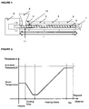
- Figure 1 is a cross section of an extruder according to the invention showing an extruder barrel (1) divided into four zones (2), (3), (4) and (5).
- the extruder screw is designated as (6) and the extrusion die at (7).
- (8) is the feed hopper and (9) is the motor that drives the extruder screw.
- Zone (2) is a cooling zone and heaters are provided in zones (3), (4) and (5) to gradually increase the temperature along the barrel, the lines (10) and (11) indicate the grooves formed in the initial cooled section of the barrel of the extruder.
- Figure 2 is a plot of a typical temperature profile along the barrel of the extruder.
- the X axis being the distance along the barrel and the Y axis is the temperature of the material.
- Figure 4 shows the extrusion die (7) provided with heaters and mounted in a heated block for attachment to the barrel of the extruder.
- Figure 5 shows how the extruder may be mounted and automatically controlled to apply an extrudate to a series of substrates.
- the extruder is mounted on a stand (13), (14) and a movement system (15), and (16) is provided.
- a series of substrates (18), (19) etc can be moved to be below the extrusion die (7) and when in position material can be extruded from the die (7) onto the substrate and the extruder may be moved in a programmed manner to provide the desired pattern of extrudate on the substrate.
- the section (6) of the extruder is cooled and the temperatures of the three heating zones (3), (4) and (5) are maintained by the controller LC.
- Pellets of material may be fed to the hopper (9) of the extruder from bulk storage (12).
- Figure 6 shows how an extrudate may be applied directly to a vehicle body on an automobile assembly line.
- the extruder (1) being movable above the car components (20, (21) and the component positioned beneath the extruder so that an extrudate of a thermohardenable adhesive may be provided for example for bonding of the roof panel.
- a groove (22) may be provided in the car body panel for receipt of the extrudate (23).
- Figure 8 shows how an extruder of the present invention may be employed to deliver an extrudate to materials on a conveyer belt line (24) moving from right to left, a series of metal components (as substrates) such as (25) may be moved along the conveyor line and thermoactivatable material extruded onto the component as it passes the extrusion die (7).
- a device (26) for pretreating the components such as with hot air to improve adhesion to the extrudate is also shown.
- thermohardenable material comprising a thermoactivable epoxy resin was employed in the apparatus of United States Patent Publication US 2003/0140671 having a heated initial section of the extruder and a length to diameter ratio of 12 with the extruder screw operating at 3 RPM and extruding the material at 90°C. After a few minutes material had built up within the extruder barrel, the extrusion was irregular and it was not possible to operate for more than 20 minutes without the need to stop and clean the extruder.
- thermoactivable epoxy resin in which the initial section of the extruder was provided with grooves and was cooled with water to below 15°C and the length/diameter ratio of the extruder was 20 and the extruder operated at 15 RPM. It was possible to run continuously for at least 40 hours without product build up and blockages.
Landscapes
- Engineering & Computer Science (AREA)
- Mechanical Engineering (AREA)
- Physics & Mathematics (AREA)
- Thermal Sciences (AREA)
- Chemical & Material Sciences (AREA)
- Chemical Kinetics & Catalysis (AREA)
- Extrusion Moulding Of Plastics Or The Like (AREA)
Description
- The present invention relates to improvements in or relating to methods for extrusion. In particular the invention relates to the extrusion of relatively low melting temperature materials and especially to materials that are thermally activatable such as thermohardenable and/or foamable at temperatures above the extrusion temperature.
- The extrusion of low melting thermoactivatable materials presents special difficulties such as blocking and sticking of the material in the barrel of the extruder due to premature melting and/or reaction of the material as it is fed to the extruder and/or in the initial zone of the extruder barrel. Typically the material is fed to the extruder as pellets or granules. The material can also melt unevenly inside the extruder causing sticking and uneven flow leading to an irregular extrudate. This in turn can lead to undesirable high residence time of the material within the extruder barrel which can cause premature activation of the material inside the extruder barrel.
- Although not limited to such the invention is particularly concerned with the application of structural adhesives to a series of components such as for example, in the mass production of automobile components such as panels. In such an automated production a series of identical parts are produced and the parts, carrying the adhesive are then employed in the automobile assembly process. In such a process it may be required to apply the adhesive in a particular pattern or array on the component and in doing so it is necessary to stop extrusion once the desired pattern or array of adhesive has been provided on one component, remove the component carrying the adhesive, replace the component with another component and then commence application of the adhesive to the new component. This process is repeated until the required number of components carrying the pattern or array of adhesive have been produced. In certain applications a discontinuous pattern or array may be required and in this instance it may be required to perform intermittent extrusion on a single component.
- In such a process when the adhesive is applied by extrusion it is necessary to have a mechanism associated with the extruder whereby the extrusion of the material can be stopped and started as required. This can also lead to increased residence time of the material within the extruder and to pre-reaction and premature hardening and/or foaming of the material in the extruder. The materials are often required as very thin strips or in a discontinuous pattern on the component which requires additional control of the extruder and presents additional processing difficulties.
- Mini extruders suitable for applying melt flowable material to components of articles of manufacture are described in United States Patent Application Publication
US 2003/0140671 . Although such extruders have been useful there are difficulties in their use in that both the throughput of material and the temperature of the material in the extruder are difficult to control which can be due to premature reaction of the material leading to sticking within the extruder. This can lead to irregularities in the size and thickness of the extrudate and can impair the programmed operation of the extruder. All of which results in undesirable short production runs due to the need for frequent stoppages for cleaning. Further processes are described inDE2754877 , -
- The present invention provides a method which overcomes some or all of these difficulties by reducing the residence time of the material within the extruder and providing enhanced flexibility to control the temperature of the material within the extruder. In addition the size of the equipment is preferably small to enable it to be readily portable from one location to another.
- The invention therefore provides a process in accordance with
claim 1. - It is preferred that the residence time of the material within the extruder is less than 10 minutes preferably less than 5 minutes.
- In addition it is preferred that the compression ratio of the extruder which is the ratio of the channel depth at the end of the extruder divided by the channel depth in the initial feed zone should be kept low in order to minimise the shear forces on the material in the extruder. Excessive shear can create energy within the material in the extruder leading to sticking and premature reaction of the material. A compression ratio in the range 1.5 to 2 is preferred. In a further preferred embodiment the length to diameter ratio of the extruder is 24 or lower, preferably between 24 and 16, more preferably between 20 and 16. This can reduce the residence time of the material within the extruder. It is also preferred that the extruder operates at between 10 and 50 revolutions of the extruder screw per minute.
- In previous systems such as those described in
US 2003/0140671 where the length to diameter ratio was about 12 extrusion of three kilograms of material per hour in an extruder of 45 mm diameter at 3 revolutions per minute results in a residence time of at least 10 minutes. According to the present invention the same amount of material can be extruded by an extruder of length to diameter ratio about 20, at 15 revolutions per minute in 3 to 4 minutes. - The material should be cooled in the initial zone of the extruder and then heated preferably at a controlled rate in a subsequent zone of the extruder and also in the extrusion die. In a preferred embodiment the temperature is gradually increased in the heating zone such as by the provision of a plurality of heaters. The selection of temperatures in the various zones will depend upon the nature of the material. Cooling can be achieved by passing a cooling fluid, such as water, around the initial zone of the reactor and we prefer that the temperature of the fluid as it leaves the cooling zone is no greater than 15 °C and preferably in the
range 5°C to 15°C. The optimum length of the cooling zone along the axis of the extruder will depend upon the nature of the material however, we prefer that the length is from two times to five times the diameter of the extruder barrel. - As the material passes from the initial cooling zone it is heated within the next zone of the barrel of the extruder to its melting temperature and again the temperatures that should be employed in the heating zone of the barrel of the extruder depends upon the nature of the material. The remainder of the barrel may be heated differentially so as to gradually bring the material to the desired extrusion temperature. Typical extrusion temperatures are in the range of 60°C to 120°C. By way of example a first heating zone may be at a temperature in the
range 20°C to 40°C, a second heating zone may be at a temperature in the range 40°C to 80°C and a final heating zone may be at a temperature in the range 80°C to 120°C which can also be employed in the extrusion die. In a preferred system there are three separate heating zones along the barrel of the extruder and a separate heating system is provided for the nozzle and extrusion die. - Where the present invention involves the intermittent extrusion of materials the direction of rotation of the screw of the extruder is reversible and is preferably reversed when it is desired to stop extrusion, this reversal helps to make a clean break in the extrudate and results in a well defined end of the extrudate on the component to which it has been applied. The reversal of the screw can be synchronised with the deposition of the extrudate on the substrate to ensure the desired pattern or array of the extrudate is produced. Where a discontinuous pattern is required the screw may be reversed and reactivated one or more times during the application to a single component.
- Another embodiment provides an extruder comprising a feed section, a barrel providing a feed section employing compression and movement of the material wherein the initial section of the barrel is cooled and is provided with grooves and the subsequent section of the barrel is heated.
The drive for the extruder may be programmed to provide intermittent extension and application of the low melting thermoactivatable material, for example the extruder screw may be reversed to stop the feed of material to the extrusion die and, in certain instances, to suck back material thus making a clean break of the extrudate. - The extruder is provided with cooling means at the initial section and it is preferred that this section extends for from two to five times the diameter of the barrel. Any suitable cooling means may be employed although we prefer to provide a jacket of cooling fluid and we prefer to operate in a manner that the temperature of the fluid leaving the cooling jacket does not exceed 15°C, preferably it does not exceed 10°C; water may be used as the cooling fluid. The remaining section of the barrel is heated and the temperature again depends upon the nature of the material being extruded. However, for the processing of thermohardenable materials employed in the automobile industry we prefer to gradually increase the temperature to an extrusion temperatures in the
range 60°C to 120°C. It is also preferred that the extruder is operated in a manner that the residence time of the material in the barrel of the extruder is less than 10 minutes, preferably less than 5 minutes. When operating with certain materials this can be accomplished by operating the extruder at a speed of from 10 to 50 revolutions per minute. - In a further embodiment when the extruder is to be used to apply a thin strip of material onto a substrate a small gap may be provided between the end of the screw of the extruder and the substrate and the extruder can be programmed so that the gap is filled immediately prior to the desired commencement of extrusion and the material can be sucked back into the gap when extrusion is to be terminated albeit temporarily.
- The nature of the extrusion die will depend upon the desired form of the extrudate. However, for the preferred application of thin strips of material a heated thin slot die is preferred. The die can be mounted at any angle and for certain applications it could be inclined at a downward angle relative to the barrel of the extruder. The die is preferably provided with a heating unit.
- The present invention allows improved control of the flow rate of the material within the extruder. In a preferred embodiment to further improve the control of the flow rate the initial section of the extruder barrel is provided with grooves and at least the initial section of the grooved section is cooled to prevent the material that is fed to the initial section from melting. Without grooves the maximum flow rate that can be achieved is less than when grooves are provided. For example with an extruder capable of operating at a screw speed of above 60 RPM with no grooves the maximum flow rate that can be achieved may be at 60 RPM after which it declines. However the provision of grooves in the initial section can allow the flow rate to be increased by increasing the revolutions of the extruder screw. The material can be conveyed as a solid in the initial section which provides a constant force to move the material through the heated sections of the extruder where it is melted and also through the die as a melt for application to the substrate. This can increase the speed at which the material moves through the extruder. The grooves are preferably equally spaced around the internal diameter of the barrel of the extruder and the preferred number, size and length of the grooves, the cooling temperature and the heating temperatures along the barrel of the extruder will depend upon the material that is being extruded. Where the extruder is used for the application of thermohardenable adhesives to automobile components extrusion temperatures of from 60°C to 120°C are typical, preferably from 60°C to 90°C.
- The extrusion die is preferably a single component with its own heating system. The nature of the die depends upon the desired shape of the extrudate but the invention is particularly useful for the extrusion of thin strips of material.
- The extruder of the present invention may be used with any substrate however, it is particularly useful for the application of patterns or arrays of material onto a substrate such as a component particularly a panel of an automobile. In order to provide the desired pattern or array of material the extruder may be moved in a predetermined manner relative to the surface of the substrate or alternatively, the substrate may be moved relative to the die of the extruder. The process may be robotically controlled and the robot can support and move the extruder while the substrate is static or the robot can move the substrate while the extruder is static. The movement can be programmed to provide the desired pattern or array on the substrate which may be a line. The pattern or array on the substrate may be continuous or discontinuous and the extruder can be programmed to stop and start extruding more than one time on a single substrate. This can be useful if a combination of spot welding and a structural adhesive is to be used to bond substrates together and no adhesive is applied where the spot welds are to be formed. In each embodiment it is preferred that the material be extruded downwards onto the surface of the substrate.
- Accordingly in a sequential operation a substrate may be placed on a table beneath the extruder die extrusion commenced and the substrate and/or the die moved relative to each other to provide the desired pattern or array of the extrudate on the substrate which may be continuous or discontinuous. Once the pattern or array is complete the extruder screw may be automatically reversed to stop extrusion and form a clean end of the pattern or array on the substrate. The substrate carrying the extrudate may be removed and replaced with the next substrate and extrusion recommenced to form the deposit on the new substrate. This process may be automated and may be performed robotically and repeated until the desired number of components (coated substrates) have been produced. The process is particularly useful for the provision of thermo hardenable adhesives on automobile components which can be activated to form bonds between components during the automobile assembly process such as at temperatures experienced in paint bake or anticorrosion coat bake ovens.
- The substrate may be pre-treated such as by heating, infra red or plasma treatment to improve the adhesion of the extrudate to the substrate.
- The extrusion techniques of the present invention may be used for the extrusion of any materials. They are however particularly useful for the extrusion of thermally activatable material at temperatures below that at which they are activate, in particularly thermohardenable epoxy based adhesive systems. Examples of thermal activation may be foaming, crosslinking or curing or a combination of the two. Where a material is to foam under the action of heat it will typically contain a blowing agent which generates the gas required to cause foaming at an activation temperature. The extruder of the present invention may be used to extrude the material at a temperature at which it will adhere to a substrate but which is below that at which the blowing agent is activated. Similarly if the material is thermohardenable and hardening is caused by the activation of a curing agent the extruder can be used to extrude the material at a temperature at which it will adhere to a substrate but which is below that at which the curing agent is activated. The extruder can be used in a similar manner with a material that both foams and cures at elevated temperature.
- The invention is therefore particularly useful for the provisions of a pattern or array of a thermoactivatable material on a component for subsequent activation. Examples of such use include the provision of structural adhesives on automobile components such as doors or body and roof panels and at locations where hem flanges are to be produced. The structural adhesives contain crosslinking agents which are activated by heat and they may be foamable according to the use to which they are to be put. Another example is where it is desirable to create a foam such as an acoustic baffle or a sealant. In this instance the desired pattern or array of the foamable material can be applied in an unfoamed state ready for foaming during the subsequent automotive assembly operation. The techniques are equally useful in other industries such as aircraft, railroad vehicles, furniture and the construction industry.
- The invention therefore enables improved material flow through the extruder, improved control of the temperature of the material and the production of a uniform extrudate over an extended period of time without the need for stoppages.
- The invention is illustrated by reference to the accompanying drawings in which
-
Figure 1 is a longitudinal cross section of an extruder according to the invention. -
Figure 2 is a plot showing the operation of the process of the present invention during one cycle of intermittent operation. -
Figure 3 is a plot showing the effect on material flow rate of providing grooves in the initial section of the extruder barrel. -
Figure 4 is a cross sectional view of the extruder nozzle and die. -
Figure 5 shows how the extruder may be used to apply material to a series of substrates.Figure 6 illustrates how the invention may be used to produce an automotive hem flange on an assembly line. -
Figure 1 is a cross section of an extruder according to the invention showing an extruder barrel (1) divided into four zones (2), (3), (4) and (5). The extruder screw is designated as (6) and the extrusion die at (7). (8) is the feed hopper and (9) is the motor that drives the extruder screw. - Zone (2) is a cooling zone and heaters are provided in zones (3), (4) and (5) to gradually increase the temperature along the barrel, the lines (10) and (11) indicate the grooves formed in the initial cooled section of the barrel of the extruder.
-
Figure 2 is a plot of a typical temperature profile along the barrel of the extruder. The X axis being the distance along the barrel and the Y axis is the temperature of the material. - In
Figure 3 Q is the flow rate of the material within the extruder and RPM is the speed of rotation of the screw of the extruder. The two curves provide a comparison that illustrates the impact of the grooves. -
Figure 4 shows the extrusion die (7) provided with heaters and mounted in a heated block for attachment to the barrel of the extruder. -
Figure 5 shows how the extruder may be mounted and automatically controlled to apply an extrudate to a series of substrates. InFigure 5 the extruder is mounted on a stand (13), (14) and a movement system (15), and (16) is provided. A series of substrates (18), (19) etc can be moved to be below the extrusion die (7) and when in
position material can be extruded from the die (7) onto the substrate and the extruder may be moved in a programmed manner to provide the desired pattern of extrudate on the substrate. The section (6) of the extruder is cooled and the temperatures of the three heating zones (3), (4) and (5) are maintained by the controller LC. - Pellets of material may be fed to the hopper (9) of the extruder from bulk storage (12).
-
Figure 6 shows how an extrudate may be applied directly to a vehicle body on an automobile assembly line. The extruder (1) being movable above the car components (20, (21) and the component positioned beneath the extruder so that an extrudate of a thermohardenable adhesive may be provided for example for bonding of the roof panel. As shown inFigure 7 a groove (22) may be provided in the car body panel for receipt of the extrudate (23). -
Figure 8 shows how an extruder of the present invention may be employed to deliver an extrudate to materials on a conveyer belt line (24) moving from right to left, a series of metal components (as substrates) such as (25) may be moved along the conveyor line and thermoactivatable material extruded onto the component as it passes the extrusion die (7). A device (26) for pretreating the components such as with hot air to improve adhesion to the extrudate is also shown. - The invention is further illustrated by comparison with the use of the method and apparatus described in United States Patent Publication
US 2003/0140671 . A thermohardenable material comprising a thermoactivable epoxy resin was employed in the apparatus of United States Patent PublicationUS 2003/0140671 having a heated initial section of the extruder and a length to diameter ratio of 12 with the extruder screw operating at 3 RPM and extruding the material at 90°C. After a few minutes material had built up within the extruder barrel, the extrusion was irregular and it was not possible to operate for more than 20 minutes without the need to stop and clean the extruder. - By comparison when employing the techniques of the present invention with the thermoactivable epoxy resin in which the initial section of the extruder was provided with grooves and was cooled with water to below 15°C and the length/diameter ratio of the extruder was 20 and the extruder operated at 15 RPM. It was possible to run continuously for at least 40 hours without product build up and blockages.
Claims (5)
- A process for the provision of thermally activatable materials on a substrate comprising extruding the material onto the substrate at a temperature below the activation temperature wherein the material is fed to an extruder, the material is cooled within the initial zone of the barrel of the extruder, heating the material to a temperature above the melting point and below the activation temperature of the material in a subsequent zone of the barrel of the extruder and extruding the molten material onto the substrate where it bonds to the substrate and cools to provide thermally activatable material on the substrate, the process being characterized in that the initial zone of the extruder is cooled by passing a cooling fluid around the initial zone of the barrel of the extruder and the temperature of the fluid is controlled so that as it leaves the cooling zone its temperature is no greater than 15°C, the thermally activatable material is a thermohardenable material and the thermally activatable material is a thermally foamable material.
- A process according to claim 1 in which the compression ratio of the extruder is from 1.5 to 2.
- A process according to any of the preceding claims in which the length of the initial zone of the barrel of the extruder is from two times to five times the diameter of the extruder barrel.
- A process according to any of the preceding claims in which the material is extruded at a temperature in the range of 60°C to 120°C.
- A process according to any of the preceding claims in which the residence time of the material in the extruder is less than 10 minutes.
Applications Claiming Priority (2)
| Application Number | Priority Date | Filing Date | Title |
|---|---|---|---|
| GBGB1102035.1A GB201102035D0 (en) | 2011-02-04 | 2011-02-04 | Improvements in or relating to extrusion |
| PCT/EP2012/000437 WO2012104071A2 (en) | 2011-02-04 | 2012-02-01 | Improvements in or relating to extrusion |
Publications (2)
| Publication Number | Publication Date |
|---|---|
| EP2670576A2 EP2670576A2 (en) | 2013-12-11 |
| EP2670576B1 true EP2670576B1 (en) | 2016-10-19 |
Family
ID=43836281
Family Applications (1)
| Application Number | Title | Priority Date | Filing Date |
|---|---|---|---|
| EP12704671.2A Active EP2670576B1 (en) | 2011-02-04 | 2012-02-01 | Improvements in or relating to extrusion |
Country Status (5)
| Country | Link |
|---|---|
| US (3) | US20140023786A1 (en) |
| EP (1) | EP2670576B1 (en) |
| CN (1) | CN103442877B (en) |
| GB (1) | GB201102035D0 (en) |
| WO (1) | WO2012104071A2 (en) |
Families Citing this family (11)
| Publication number | Priority date | Publication date | Assignee | Title |
|---|---|---|---|---|
| GB201102035D0 (en) | 2011-02-04 | 2011-03-23 | Zephyros Inc | Improvements in or relating to extrusion |
| GB201207481D0 (en) | 2012-04-26 | 2012-06-13 | Zephyros Inc | Applying flowable materials to synthetic substrates |
| GB201300483D0 (en) | 2013-01-11 | 2013-02-27 | Zephyros Inc | Extrusion of bands of material |
| US9145629B2 (en) * | 2014-02-03 | 2015-09-29 | Nike, Inc. | Article of footwear including a monofilament knit element with a fusible strand |
| EP3445566B1 (en) * | 2016-05-12 | 2021-09-15 | Hewlett-Packard Development Company, L.P. | Heater for 3d printer auger screw |
| US10589060B2 (en) | 2016-12-21 | 2020-03-17 | Biosense Webster (Israel) Ltd. | Extrusion with preferential bend axis |
| DE102018001613B4 (en) * | 2018-02-21 | 2021-02-11 | Diehl Aviation Laupheim Gmbh | Method for producing a plastic component and plastic component |
| CN111516199B (en) * | 2020-04-20 | 2022-04-15 | 温州飞龙聚氨酯设备工程有限公司 | Polyurethane foaming machine |
| CN119836449A (en) | 2022-09-05 | 2025-04-15 | 泽费罗斯股份有限公司 | Curable polymer composition with improved wash-off resistance |
| CN115320054B (en) * | 2022-10-13 | 2023-02-10 | 晋江山水橡塑机械制造有限公司 | Bipyramid extrusion tablet press with return hopper structure |
| CN115871190A (en) * | 2022-12-14 | 2023-03-31 | 济南嗒凛洺鄢生物科技有限公司 | Tubulation mould of PVC inside lining cable pipe |
Citations (10)
| Publication number | Priority date | Publication date | Assignee | Title |
|---|---|---|---|---|
| DE1704824A1 (en) | 1966-04-13 | 1971-05-19 | Mobil Oil Corp | Method and device for producing or discharging thermoplastic foam material |
| US4178337A (en) | 1977-10-18 | 1979-12-11 | Johnson & Johnson | Thermoplastic elastomeric film extrusion process |
| EP0112290A2 (en) | 1982-12-21 | 1984-06-27 | Maillefer S.A. | Screw extruder for plastic material |
| US5358397A (en) | 1993-05-10 | 1994-10-25 | L&L Products, Inc. | Apparatus for extruding flowable materials |
| US6328919B1 (en) | 1999-02-16 | 2001-12-11 | The Dow Chemical Company | Method for extruding polycarbonate of low bulk density |
| DE10224707A1 (en) | 2001-06-06 | 2002-12-12 | Uponor Innovation Ab | Extruded multi-layer flame resistant pipe for sprinkler systems, gas, pneumatic or hydraulic pipes, has a flame retardant and reinforced outer layer |
| EP1331080A2 (en) | 2002-01-25 | 2003-07-30 | L & L Products Inc. | Method and apparatus for applying flowable materials like polyurethane or epoxy resin after pretreating the surface with plasma or primer |
| WO2005002950A2 (en) | 2003-06-26 | 2005-01-13 | L & L Products, Inc. | Expandable material and fastenable member for sealing, baffling or reinforcing and method of forming same |
| EP1582268A1 (en) | 2004-03-31 | 2005-10-05 | L & L Products Inc. | Method of applying activatable material to a member |
| WO2009091953A2 (en) | 2008-01-16 | 2009-07-23 | Sika Technology Ag | Extruded expandable barrier |
Family Cites Families (22)
| Publication number | Priority date | Publication date | Assignee | Title |
|---|---|---|---|---|
| US2686335A (en) * | 1951-03-20 | 1954-08-17 | Frank R Gross | Plastic extrusion |
| US2958099A (en) * | 1959-01-15 | 1960-11-01 | Dow Chemical Co | Extrusion die for plastic extruders |
| US3579728A (en) * | 1965-07-09 | 1971-05-25 | Phillips Petroleum Co | Polymer separation |
| US3526929A (en) * | 1967-11-24 | 1970-09-08 | Shell Oil Co | Apparatus for minimizing terminal drool in intermittent-charge plastic extrusion apparatus |
| US3767754A (en) * | 1968-11-15 | 1973-10-23 | Allied Chem | Method for melting and dispersion of thermoplastic polymers |
| US3870284A (en) * | 1972-08-23 | 1975-03-11 | Koehring Co | Extruder screws |
| US4032501A (en) * | 1975-07-11 | 1977-06-28 | The Firestone Tire & Rubber Company | Dry-blendable solution rubber powders and process |
| DE2754877B1 (en) * | 1977-12-09 | 1979-02-22 | Felten & Guilleaume Carlswerk | Method and device for producing an extruded article, in particular an insulating sleeve of an electrical cable |
| US4330214A (en) * | 1980-02-19 | 1982-05-18 | W. H. Willert, Inc. | Plasticizing screw |
| KR0130822B1 (en) * | 1988-05-13 | 1998-04-07 | 제임즈 제이 플린 | Grafted, Multi-Phase, Thermoplastic Elastomer Compositions and Methods of Making the Same |
| US6235288B1 (en) * | 1992-08-26 | 2001-05-22 | The Scripps Research Institute | Peptides for inducing cytotoxic T lymphocyte responses to hepatitis B virus |
| US5750061A (en) * | 1995-11-07 | 1998-05-12 | Lonza Inc. | Halohydantoin forms produced by melt extrusion and method for making |
| US5922425A (en) * | 1996-05-28 | 1999-07-13 | Minnesota Mining And Manufacturing Company | Multi-layer compositions and articles comprising fluorine-containing polymer |
| US5909958A (en) | 1997-04-25 | 1999-06-08 | Rauwendaal Extrusion Engineering, Inc. | Screw extruder with independently adjustable groove depth |
| EP0998381B2 (en) * | 1997-07-25 | 2010-05-05 | Metabolix, Inc. | Method of producing polyhydroxyalkanoate coatings |
| US6103152A (en) * | 1998-07-31 | 2000-08-15 | 3M Innovative Properties Co. | Articles that include a polymer foam and method for preparing same |
| US6210030B1 (en) * | 1999-06-15 | 2001-04-03 | Jean-Pierre Ibar | Method and apparatus to control viscosity of molten plastics prior to a molding operation |
| DE19939073A1 (en) | 1999-08-18 | 2001-02-22 | Beiersdorf Ag | Process for the continuous, solvent and mastication-free production of pressure-sensitive self-adhesive compositions based on non-thermoplastic elastomers and their coating for the production of self-adhesive articles |
| CA2347872A1 (en) * | 2000-05-18 | 2001-11-18 | National Starch And Chemical Investment Holding Corporation | Die attach adhesives with vinyl ether and carbamate or urea functionality |
| US7479245B2 (en) * | 2003-06-26 | 2009-01-20 | Zephyros, Inc. | Process for applying a material to a member |
| US20120082784A1 (en) * | 2009-04-10 | 2012-04-05 | SUN-GOOD GLUE COMPANY, Ltd. | Hot-melt extruded adhesive tape |
| GB201102035D0 (en) | 2011-02-04 | 2011-03-23 | Zephyros Inc | Improvements in or relating to extrusion |
-
2011
- 2011-02-04 GB GBGB1102035.1A patent/GB201102035D0/en not_active Ceased
-
2012
- 2012-02-01 EP EP12704671.2A patent/EP2670576B1/en active Active
- 2012-02-01 WO PCT/EP2012/000437 patent/WO2012104071A2/en not_active Ceased
- 2012-02-01 CN CN201280011612.XA patent/CN103442877B/en active Active
- 2012-02-01 US US13/982,080 patent/US20140023786A1/en not_active Abandoned
-
2020
- 2020-06-26 US US16/913,701 patent/US11590530B2/en active Active
-
2022
- 2022-12-28 US US18/090,044 patent/US12325047B2/en active Active
Patent Citations (11)
| Publication number | Priority date | Publication date | Assignee | Title |
|---|---|---|---|---|
| DE1704824A1 (en) | 1966-04-13 | 1971-05-19 | Mobil Oil Corp | Method and device for producing or discharging thermoplastic foam material |
| US4178337A (en) | 1977-10-18 | 1979-12-11 | Johnson & Johnson | Thermoplastic elastomeric film extrusion process |
| EP0112290A2 (en) | 1982-12-21 | 1984-06-27 | Maillefer S.A. | Screw extruder for plastic material |
| US5358397A (en) | 1993-05-10 | 1994-10-25 | L&L Products, Inc. | Apparatus for extruding flowable materials |
| US6328919B1 (en) | 1999-02-16 | 2001-12-11 | The Dow Chemical Company | Method for extruding polycarbonate of low bulk density |
| DE10224707A1 (en) | 2001-06-06 | 2002-12-12 | Uponor Innovation Ab | Extruded multi-layer flame resistant pipe for sprinkler systems, gas, pneumatic or hydraulic pipes, has a flame retardant and reinforced outer layer |
| EP1331080A2 (en) | 2002-01-25 | 2003-07-30 | L & L Products Inc. | Method and apparatus for applying flowable materials like polyurethane or epoxy resin after pretreating the surface with plasma or primer |
| US20060127584A1 (en) | 2002-01-25 | 2006-06-15 | L&L Products, Inc. | Method and apparatus for applying flowable materials |
| WO2005002950A2 (en) | 2003-06-26 | 2005-01-13 | L & L Products, Inc. | Expandable material and fastenable member for sealing, baffling or reinforcing and method of forming same |
| EP1582268A1 (en) | 2004-03-31 | 2005-10-05 | L & L Products Inc. | Method of applying activatable material to a member |
| WO2009091953A2 (en) | 2008-01-16 | 2009-07-23 | Sika Technology Ag | Extruded expandable barrier |
Also Published As
| Publication number | Publication date |
|---|---|
| US11590530B2 (en) | 2023-02-28 |
| CN103442877A (en) | 2013-12-11 |
| EP2670576A2 (en) | 2013-12-11 |
| WO2012104071A2 (en) | 2012-08-09 |
| US20230201873A1 (en) | 2023-06-29 |
| CN103442877B (en) | 2017-03-01 |
| GB201102035D0 (en) | 2011-03-23 |
| US12325047B2 (en) | 2025-06-10 |
| WO2012104071A3 (en) | 2012-11-15 |
| US20140023786A1 (en) | 2014-01-23 |
| US20200324317A1 (en) | 2020-10-15 |
Similar Documents
| Publication | Publication Date | Title |
|---|---|---|
| US12325047B2 (en) | Extrusion method and apparatus | |
| US11986855B2 (en) | Process and apparatus for extruding bands of material onto a substrate | |
| EP1331080B1 (en) | Method for applying foamable flowable materials to vehicle components | |
| JP3353914B2 (en) | METHOD AND APPARATUS FOR MANUFACTURING ARTICLES HAVING DEFORMED EDGE | |
| EP0768923B1 (en) | Method and apparatus for the application of liquid materials onto substrates | |
| EP2934766B1 (en) | Method for the sound damping and/or sound insulation of components | |
| CN1599660A (en) | Liquefier pump control in extrusion equipment | |
| CA2866297C (en) | Method for discharging a volume flow | |
| KR20130133829A (en) | Method and device for applying liquid reaction mixtures to a cover layer | |
| JP5721943B2 (en) | Extrusion of composite structural adhesives | |
| EP2841211B1 (en) | Applying flowable materials to synthetic substrates | |
| US20160108511A1 (en) | Spray-coating method | |
| JP4427762B2 (en) | Method and apparatus for forming glazing gasket for multi-layer glass panel | |
| EP1368176B1 (en) | Apparatus and process for extruding a profile on a glazing | |
| HK1068577A1 (en) | An extrusion apparatus and a method of melt flow compensation in the extrusion apparatus | |
| HK1068577B (en) | An extrusion apparatus and a method of melt flow compensation in the extrusion apparatus |
Legal Events
| Date | Code | Title | Description |
|---|---|---|---|
| PUAI | Public reference made under article 153(3) epc to a published international application that has entered the european phase |
Free format text: ORIGINAL CODE: 0009012 |
|
| 17P | Request for examination filed |
Effective date: 20130830 |
|
| AK | Designated contracting states |
Kind code of ref document: A2 Designated state(s): AL AT BE BG CH CY CZ DE DK EE ES FI FR GB GR HR HU IE IS IT LI LT LU LV MC MK MT NL NO PL PT RO RS SE SI SK SM TR |
|
| DAX | Request for extension of the european patent (deleted) | ||
| 17Q | First examination report despatched |
Effective date: 20141021 |
|
| GRAP | Despatch of communication of intention to grant a patent |
Free format text: ORIGINAL CODE: EPIDOSNIGR1 |
|
| INTG | Intention to grant announced |
Effective date: 20160506 |
|
| GRAS | Grant fee paid |
Free format text: ORIGINAL CODE: EPIDOSNIGR3 |
|
| GRAA | (expected) grant |
Free format text: ORIGINAL CODE: 0009210 |
|
| AK | Designated contracting states |
Kind code of ref document: B1 Designated state(s): AL AT BE BG CH CY CZ DE DK EE ES FI FR GB GR HR HU IE IS IT LI LT LU LV MC MK MT NL NO PL PT RO RS SE SI SK SM TR |
|
| REG | Reference to a national code |
Ref country code: GB Ref legal event code: FG4D |
|
| REG | Reference to a national code |
Ref country code: CH Ref legal event code: EP |
|
| REG | Reference to a national code |
Ref country code: AT Ref legal event code: REF Ref document number: 837949 Country of ref document: AT Kind code of ref document: T Effective date: 20161115 |
|
| REG | Reference to a national code |
Ref country code: IE Ref legal event code: FG4D |
|
| REG | Reference to a national code |
Ref country code: DE Ref legal event code: R096 Ref document number: 602012024287 Country of ref document: DE |
|
| REG | Reference to a national code |
Ref country code: FR Ref legal event code: PLFP Year of fee payment: 6 |
|
| REG | Reference to a national code |
Ref country code: NL Ref legal event code: MP Effective date: 20161019 |
|
| REG | Reference to a national code |
Ref country code: LT Ref legal event code: MG4D |
|
| PG25 | Lapsed in a contracting state [announced via postgrant information from national office to epo] |
Ref country code: LV Free format text: LAPSE BECAUSE OF FAILURE TO SUBMIT A TRANSLATION OF THE DESCRIPTION OR TO PAY THE FEE WITHIN THE PRESCRIBED TIME-LIMIT Effective date: 20161019 |
|
| REG | Reference to a national code |
Ref country code: AT Ref legal event code: MK05 Ref document number: 837949 Country of ref document: AT Kind code of ref document: T Effective date: 20161019 |
|
| PG25 | Lapsed in a contracting state [announced via postgrant information from national office to epo] |
Ref country code: SE Free format text: LAPSE BECAUSE OF FAILURE TO SUBMIT A TRANSLATION OF THE DESCRIPTION OR TO PAY THE FEE WITHIN THE PRESCRIBED TIME-LIMIT Effective date: 20161019 Ref country code: LT Free format text: LAPSE BECAUSE OF FAILURE TO SUBMIT A TRANSLATION OF THE DESCRIPTION OR TO PAY THE FEE WITHIN THE PRESCRIBED TIME-LIMIT Effective date: 20161019 Ref country code: GR Free format text: LAPSE BECAUSE OF FAILURE TO SUBMIT A TRANSLATION OF THE DESCRIPTION OR TO PAY THE FEE WITHIN THE PRESCRIBED TIME-LIMIT Effective date: 20170120 Ref country code: NO Free format text: LAPSE BECAUSE OF FAILURE TO SUBMIT A TRANSLATION OF THE DESCRIPTION OR TO PAY THE FEE WITHIN THE PRESCRIBED TIME-LIMIT Effective date: 20170119 |
|
| PG25 | Lapsed in a contracting state [announced via postgrant information from national office to epo] |
Ref country code: RS Free format text: LAPSE BECAUSE OF FAILURE TO SUBMIT A TRANSLATION OF THE DESCRIPTION OR TO PAY THE FEE WITHIN THE PRESCRIBED TIME-LIMIT Effective date: 20161019 Ref country code: IS Free format text: LAPSE BECAUSE OF FAILURE TO SUBMIT A TRANSLATION OF THE DESCRIPTION OR TO PAY THE FEE WITHIN THE PRESCRIBED TIME-LIMIT Effective date: 20170219 Ref country code: PT Free format text: LAPSE BECAUSE OF FAILURE TO SUBMIT A TRANSLATION OF THE DESCRIPTION OR TO PAY THE FEE WITHIN THE PRESCRIBED TIME-LIMIT Effective date: 20170220 Ref country code: BE Free format text: LAPSE BECAUSE OF FAILURE TO SUBMIT A TRANSLATION OF THE DESCRIPTION OR TO PAY THE FEE WITHIN THE PRESCRIBED TIME-LIMIT Effective date: 20161019 Ref country code: HR Free format text: LAPSE BECAUSE OF FAILURE TO SUBMIT A TRANSLATION OF THE DESCRIPTION OR TO PAY THE FEE WITHIN THE PRESCRIBED TIME-LIMIT Effective date: 20161019 Ref country code: AT Free format text: LAPSE BECAUSE OF FAILURE TO SUBMIT A TRANSLATION OF THE DESCRIPTION OR TO PAY THE FEE WITHIN THE PRESCRIBED TIME-LIMIT Effective date: 20161019 Ref country code: ES Free format text: LAPSE BECAUSE OF FAILURE TO SUBMIT A TRANSLATION OF THE DESCRIPTION OR TO PAY THE FEE WITHIN THE PRESCRIBED TIME-LIMIT Effective date: 20161019 Ref country code: NL Free format text: LAPSE BECAUSE OF FAILURE TO SUBMIT A TRANSLATION OF THE DESCRIPTION OR TO PAY THE FEE WITHIN THE PRESCRIBED TIME-LIMIT Effective date: 20161019 Ref country code: FI Free format text: LAPSE BECAUSE OF FAILURE TO SUBMIT A TRANSLATION OF THE DESCRIPTION OR TO PAY THE FEE WITHIN THE PRESCRIBED TIME-LIMIT Effective date: 20161019 Ref country code: PL Free format text: LAPSE BECAUSE OF FAILURE TO SUBMIT A TRANSLATION OF THE DESCRIPTION OR TO PAY THE FEE WITHIN THE PRESCRIBED TIME-LIMIT Effective date: 20161019 |
|
| REG | Reference to a national code |
Ref country code: DE Ref legal event code: R026 Ref document number: 602012024287 Country of ref document: DE |
|
| PLBI | Opposition filed |
Free format text: ORIGINAL CODE: 0009260 |
|
| PG25 | Lapsed in a contracting state [announced via postgrant information from national office to epo] |
Ref country code: SK Free format text: LAPSE BECAUSE OF FAILURE TO SUBMIT A TRANSLATION OF THE DESCRIPTION OR TO PAY THE FEE WITHIN THE PRESCRIBED TIME-LIMIT Effective date: 20161019 Ref country code: RO Free format text: LAPSE BECAUSE OF FAILURE TO SUBMIT A TRANSLATION OF THE DESCRIPTION OR TO PAY THE FEE WITHIN THE PRESCRIBED TIME-LIMIT Effective date: 20161019 Ref country code: CZ Free format text: LAPSE BECAUSE OF FAILURE TO SUBMIT A TRANSLATION OF THE DESCRIPTION OR TO PAY THE FEE WITHIN THE PRESCRIBED TIME-LIMIT Effective date: 20161019 Ref country code: DK Free format text: LAPSE BECAUSE OF FAILURE TO SUBMIT A TRANSLATION OF THE DESCRIPTION OR TO PAY THE FEE WITHIN THE PRESCRIBED TIME-LIMIT Effective date: 20161019 Ref country code: EE Free format text: LAPSE BECAUSE OF FAILURE TO SUBMIT A TRANSLATION OF THE DESCRIPTION OR TO PAY THE FEE WITHIN THE PRESCRIBED TIME-LIMIT Effective date: 20161019 |
|
| PLAX | Notice of opposition and request to file observation + time limit sent |
Free format text: ORIGINAL CODE: EPIDOSNOBS2 |
|
| 26 | Opposition filed |
Opponent name: SIKA TECHNOLOGY AG Effective date: 20170714 |
|
| PG25 | Lapsed in a contracting state [announced via postgrant information from national office to epo] |
Ref country code: BG Free format text: LAPSE BECAUSE OF FAILURE TO SUBMIT A TRANSLATION OF THE DESCRIPTION OR TO PAY THE FEE WITHIN THE PRESCRIBED TIME-LIMIT Effective date: 20170119 Ref country code: SM Free format text: LAPSE BECAUSE OF FAILURE TO SUBMIT A TRANSLATION OF THE DESCRIPTION OR TO PAY THE FEE WITHIN THE PRESCRIBED TIME-LIMIT Effective date: 20161019 Ref country code: IT Free format text: LAPSE BECAUSE OF FAILURE TO SUBMIT A TRANSLATION OF THE DESCRIPTION OR TO PAY THE FEE WITHIN THE PRESCRIBED TIME-LIMIT Effective date: 20161019 |
|
| PG25 | Lapsed in a contracting state [announced via postgrant information from national office to epo] |
Ref country code: MC Free format text: LAPSE BECAUSE OF FAILURE TO SUBMIT A TRANSLATION OF THE DESCRIPTION OR TO PAY THE FEE WITHIN THE PRESCRIBED TIME-LIMIT Effective date: 20161019 |
|
| REG | Reference to a national code |
Ref country code: CH Ref legal event code: PL |
|
| GBPC | Gb: european patent ceased through non-payment of renewal fee |
Effective date: 20170201 |
|
| PG25 | Lapsed in a contracting state [announced via postgrant information from national office to epo] |
Ref country code: LI Free format text: LAPSE BECAUSE OF NON-PAYMENT OF DUE FEES Effective date: 20170228 Ref country code: CH Free format text: LAPSE BECAUSE OF NON-PAYMENT OF DUE FEES Effective date: 20170228 |
|
| REG | Reference to a national code |
Ref country code: IE Ref legal event code: MM4A |
|
| PG25 | Lapsed in a contracting state [announced via postgrant information from national office to epo] |
Ref country code: SI Free format text: LAPSE BECAUSE OF FAILURE TO SUBMIT A TRANSLATION OF THE DESCRIPTION OR TO PAY THE FEE WITHIN THE PRESCRIBED TIME-LIMIT Effective date: 20161019 |
|
| PG25 | Lapsed in a contracting state [announced via postgrant information from national office to epo] |
Ref country code: LU Free format text: LAPSE BECAUSE OF NON-PAYMENT OF DUE FEES Effective date: 20170201 |
|
| PLBB | Reply of patent proprietor to notice(s) of opposition received |
Free format text: ORIGINAL CODE: EPIDOSNOBS3 |
|
| REG | Reference to a national code |
Ref country code: FR Ref legal event code: PLFP Year of fee payment: 7 |
|
| PG25 | Lapsed in a contracting state [announced via postgrant information from national office to epo] |
Ref country code: GB Free format text: LAPSE BECAUSE OF NON-PAYMENT OF DUE FEES Effective date: 20170201 Ref country code: IE Free format text: LAPSE BECAUSE OF NON-PAYMENT OF DUE FEES Effective date: 20170201 |
|
| PG25 | Lapsed in a contracting state [announced via postgrant information from national office to epo] |
Ref country code: MT Free format text: LAPSE BECAUSE OF NON-PAYMENT OF DUE FEES Effective date: 20170201 |
|
| REG | Reference to a national code |
Ref country code: DE Ref legal event code: R079 Ref document number: 602012024287 Country of ref document: DE Free format text: PREVIOUS MAIN CLASS: B29C0047000000 Ipc: B29C0048000000 |
|
| REG | Reference to a national code |
Ref country code: DE Ref legal event code: R100 Ref document number: 602012024287 Country of ref document: DE |
|
| PG25 | Lapsed in a contracting state [announced via postgrant information from national office to epo] |
Ref country code: HU Free format text: LAPSE BECAUSE OF FAILURE TO SUBMIT A TRANSLATION OF THE DESCRIPTION OR TO PAY THE FEE WITHIN THE PRESCRIBED TIME-LIMIT; INVALID AB INITIO Effective date: 20120201 |
|
| PLCK | Communication despatched that opposition was rejected |
Free format text: ORIGINAL CODE: EPIDOSNREJ1 |
|
| STAA | Information on the status of an ep patent application or granted ep patent |
Free format text: STATUS: THE PATENT HAS BEEN GRANTED |
|
| PG25 | Lapsed in a contracting state [announced via postgrant information from national office to epo] |
Ref country code: CY Free format text: LAPSE BECAUSE OF NON-PAYMENT OF DUE FEES Effective date: 20161019 |
|
| PLBN | Opposition rejected |
Free format text: ORIGINAL CODE: 0009273 |
|
| STAA | Information on the status of an ep patent application or granted ep patent |
Free format text: STATUS: OPPOSITION REJECTED |
|
| PG25 | Lapsed in a contracting state [announced via postgrant information from national office to epo] |
Ref country code: MK Free format text: LAPSE BECAUSE OF FAILURE TO SUBMIT A TRANSLATION OF THE DESCRIPTION OR TO PAY THE FEE WITHIN THE PRESCRIBED TIME-LIMIT Effective date: 20161019 |
|
| 27O | Opposition rejected |
Effective date: 20190207 |
|
| PG25 | Lapsed in a contracting state [announced via postgrant information from national office to epo] |
Ref country code: TR Free format text: LAPSE BECAUSE OF FAILURE TO SUBMIT A TRANSLATION OF THE DESCRIPTION OR TO PAY THE FEE WITHIN THE PRESCRIBED TIME-LIMIT Effective date: 20161019 |
|
| PG25 | Lapsed in a contracting state [announced via postgrant information from national office to epo] |
Ref country code: AL Free format text: LAPSE BECAUSE OF FAILURE TO SUBMIT A TRANSLATION OF THE DESCRIPTION OR TO PAY THE FEE WITHIN THE PRESCRIBED TIME-LIMIT Effective date: 20161019 |
|
| P01 | Opt-out of the competence of the unified patent court (upc) registered |
Effective date: 20230522 |
|
| PGFP | Annual fee paid to national office [announced via postgrant information from national office to epo] |
Ref country code: DE Payment date: 20260218 Year of fee payment: 15 |
|
| PGFP | Annual fee paid to national office [announced via postgrant information from national office to epo] |
Ref country code: FR Payment date: 20260218 Year of fee payment: 15 |