EP2669896A1 - Coil assembly for a control rod driver having improved thermal resistance, and method for manufacturing same - Google Patents
Coil assembly for a control rod driver having improved thermal resistance, and method for manufacturing same Download PDFInfo
- Publication number
- EP2669896A1 EP2669896A1 EP11856834.4A EP11856834A EP2669896A1 EP 2669896 A1 EP2669896 A1 EP 2669896A1 EP 11856834 A EP11856834 A EP 11856834A EP 2669896 A1 EP2669896 A1 EP 2669896A1
- Authority
- EP
- European Patent Office
- Prior art keywords
- coil
- wire
- control rod
- coating layer
- layer
- Prior art date
- Legal status (The legal status is an assumption and is not a legal conclusion. Google has not performed a legal analysis and makes no representation as to the accuracy of the status listed.)
- Granted
Links
Images



Classifications
-
- H—ELECTRICITY
- H01—ELECTRIC ELEMENTS
- H01F—MAGNETS; INDUCTANCES; TRANSFORMERS; SELECTION OF MATERIALS FOR THEIR MAGNETIC PROPERTIES
- H01F27/00—Details of transformers or inductances, in general
- H01F27/02—Casings
- H01F27/022—Encapsulation
-
- G—PHYSICS
- G09—EDUCATION; CRYPTOGRAPHY; DISPLAY; ADVERTISING; SEALS
- G09F—DISPLAYING; ADVERTISING; SIGNS; LABELS OR NAME-PLATES; SEALS
- G09F9/00—Indicating arrangements for variable information in which the information is built-up on a support by selection or combination of individual elements
- G09F9/30—Indicating arrangements for variable information in which the information is built-up on a support by selection or combination of individual elements in which the desired character or characters are formed by combining individual elements
- G09F9/33—Indicating arrangements for variable information in which the information is built-up on a support by selection or combination of individual elements in which the desired character or characters are formed by combining individual elements being semiconductor devices, e.g. diodes
-
- G—PHYSICS
- G21—NUCLEAR PHYSICS; NUCLEAR ENGINEERING
- G21C—NUCLEAR REACTORS
- G21C7/00—Control of nuclear reaction
- G21C7/06—Control of nuclear reaction by application of neutron-absorbing material, i.e. material with absorption cross-section very much in excess of reflection cross-section
- G21C7/08—Control of nuclear reaction by application of neutron-absorbing material, i.e. material with absorption cross-section very much in excess of reflection cross-section by displacement of solid control elements, e.g. control rods
- G21C7/10—Construction of control elements
-
- G—PHYSICS
- G09—EDUCATION; CRYPTOGRAPHY; DISPLAY; ADVERTISING; SEALS
- G09F—DISPLAYING; ADVERTISING; SIGNS; LABELS OR NAME-PLATES; SEALS
- G09F13/00—Illuminated signs; Luminous advertising
- G09F13/20—Illuminated signs; Luminous advertising with luminescent surfaces or parts
- G09F13/22—Illuminated signs; Luminous advertising with luminescent surfaces or parts electroluminescent
-
- G—PHYSICS
- G09—EDUCATION; CRYPTOGRAPHY; DISPLAY; ADVERTISING; SEALS
- G09F—DISPLAYING; ADVERTISING; SIGNS; LABELS OR NAME-PLATES; SEALS
- G09F7/00—Signs, name or number plates, letters, numerals, or symbols; Panels or boards
- G09F7/02—Signs, plates, panels or boards using readily-detachable elements bearing or forming symbols
- G09F7/12—Signs, plates, panels or boards using readily-detachable elements bearing or forming symbols the elements being secured or adapted to be secured by self-adhesion, moisture, suction, slow-drying adhesive or the like
-
- G—PHYSICS
- G09—EDUCATION; CRYPTOGRAPHY; DISPLAY; ADVERTISING; SEALS
- G09F—DISPLAYING; ADVERTISING; SIGNS; LABELS OR NAME-PLATES; SEALS
- G09F9/00—Indicating arrangements for variable information in which the information is built-up on a support by selection or combination of individual elements
- G09F9/30—Indicating arrangements for variable information in which the information is built-up on a support by selection or combination of individual elements in which the desired character or characters are formed by combining individual elements
- G09F9/301—Indicating arrangements for variable information in which the information is built-up on a support by selection or combination of individual elements in which the desired character or characters are formed by combining individual elements flexible foldable or roll-able electronic displays, e.g. thin LCD, OLED
-
- G—PHYSICS
- G21—NUCLEAR PHYSICS; NUCLEAR ENGINEERING
- G21C—NUCLEAR REACTORS
- G21C21/00—Apparatus or processes specially adapted to the manufacture of reactors or parts thereof
- G21C21/18—Manufacture of control elements covered by group G21C7/00
-
- G—PHYSICS
- G21—NUCLEAR PHYSICS; NUCLEAR ENGINEERING
- G21C—NUCLEAR REACTORS
- G21C7/00—Control of nuclear reaction
- G21C7/06—Control of nuclear reaction by application of neutron-absorbing material, i.e. material with absorption cross-section very much in excess of reflection cross-section
- G21C7/08—Control of nuclear reaction by application of neutron-absorbing material, i.e. material with absorption cross-section very much in excess of reflection cross-section by displacement of solid control elements, e.g. control rods
- G21C7/12—Means for moving control elements to desired position
-
- H—ELECTRICITY
- H01—ELECTRIC ELEMENTS
- H01F—MAGNETS; INDUCTANCES; TRANSFORMERS; SELECTION OF MATERIALS FOR THEIR MAGNETIC PROPERTIES
- H01F41/00—Apparatus or processes specially adapted for manufacturing or assembling magnets, inductances or transformers; Apparatus or processes specially adapted for manufacturing materials characterised by their magnetic properties
- H01F41/02—Apparatus or processes specially adapted for manufacturing or assembling magnets, inductances or transformers; Apparatus or processes specially adapted for manufacturing materials characterised by their magnetic properties for manufacturing cores, coils, or magnets
- H01F41/04—Apparatus or processes specially adapted for manufacturing or assembling magnets, inductances or transformers; Apparatus or processes specially adapted for manufacturing materials characterised by their magnetic properties for manufacturing cores, coils, or magnets for manufacturing coils
- H01F41/12—Insulating of windings
- H01F41/127—Encapsulating or impregnating
-
- H—ELECTRICITY
- H01—ELECTRIC ELEMENTS
- H01F—MAGNETS; INDUCTANCES; TRANSFORMERS; SELECTION OF MATERIALS FOR THEIR MAGNETIC PROPERTIES
- H01F5/00—Coils
- H01F5/06—Insulation of windings
-
- G—PHYSICS
- G09—EDUCATION; CRYPTOGRAPHY; DISPLAY; ADVERTISING; SEALS
- G09F—DISPLAYING; ADVERTISING; SIGNS; LABELS OR NAME-PLATES; SEALS
- G09F7/00—Signs, name or number plates, letters, numerals, or symbols; Panels or boards
- G09F7/02—Signs, plates, panels or boards using readily-detachable elements bearing or forming symbols
- G09F7/12—Signs, plates, panels or boards using readily-detachable elements bearing or forming symbols the elements being secured or adapted to be secured by self-adhesion, moisture, suction, slow-drying adhesive or the like
- G09F2007/127—Signs, plates, panels or boards using readily-detachable elements bearing or forming symbols the elements being secured or adapted to be secured by self-adhesion, moisture, suction, slow-drying adhesive or the like by adhesive
-
- G—PHYSICS
- G09—EDUCATION; CRYPTOGRAPHY; DISPLAY; ADVERTISING; SEALS
- G09F—DISPLAYING; ADVERTISING; SIGNS; LABELS OR NAME-PLATES; SEALS
- G09F13/00—Illuminated signs; Luminous advertising
- G09F13/20—Illuminated signs; Luminous advertising with luminescent surfaces or parts
- G09F13/22—Illuminated signs; Luminous advertising with luminescent surfaces or parts electroluminescent
- G09F2013/222—Illuminated signs; Luminous advertising with luminescent surfaces or parts electroluminescent with LEDs
-
- H—ELECTRICITY
- H01—ELECTRIC ELEMENTS
- H01F—MAGNETS; INDUCTANCES; TRANSFORMERS; SELECTION OF MATERIALS FOR THEIR MAGNETIC PROPERTIES
- H01F27/00—Details of transformers or inductances, in general
- H01F27/28—Coils; Windings; Conductive connections
- H01F27/32—Insulating of coils, windings, or parts thereof
- H01F27/327—Encapsulating or impregnating
-
- Y—GENERAL TAGGING OF NEW TECHNOLOGICAL DEVELOPMENTS; GENERAL TAGGING OF CROSS-SECTIONAL TECHNOLOGIES SPANNING OVER SEVERAL SECTIONS OF THE IPC; TECHNICAL SUBJECTS COVERED BY FORMER USPC CROSS-REFERENCE ART COLLECTIONS [XRACs] AND DIGESTS
- Y02—TECHNOLOGIES OR APPLICATIONS FOR MITIGATION OR ADAPTATION AGAINST CLIMATE CHANGE
- Y02E—REDUCTION OF GREENHOUSE GAS [GHG] EMISSIONS, RELATED TO ENERGY GENERATION, TRANSMISSION OR DISTRIBUTION
- Y02E30/00—Energy generation of nuclear origin
- Y02E30/30—Nuclear fission reactors
-
- Y—GENERAL TAGGING OF NEW TECHNOLOGICAL DEVELOPMENTS; GENERAL TAGGING OF CROSS-SECTIONAL TECHNOLOGIES SPANNING OVER SEVERAL SECTIONS OF THE IPC; TECHNICAL SUBJECTS COVERED BY FORMER USPC CROSS-REFERENCE ART COLLECTIONS [XRACs] AND DIGESTS
- Y10—TECHNICAL SUBJECTS COVERED BY FORMER USPC
- Y10S—TECHNICAL SUBJECTS COVERED BY FORMER USPC CROSS-REFERENCE ART COLLECTIONS [XRACs] AND DIGESTS
- Y10S362/00—Illumination
- Y10S362/80—Light emitting diode
Definitions
- the present invention relates to a coil assembly for a control rod driver for driving a nuclear power plant and a method for manufacturing the same, and more particularly, to a coil assembly for a control rod driver having improved thermal resistance in which coil deterioration is reduced by improving the heat resistance and thermal conductivity of coils to securely prevent coil deterioration and the fall of a control rod, caused by continuous operations of the control rod driver during an automatic load follow operation, thereby improving the safety and economic feasibility of a nuclear power plant, and a method for manufacturing the same.
- a nuclear reactor is a device designed to gradually discharge a large amount of energy that is instantaneously emitted due to a mass defect occurring during nuclear fission of a nuclear fuel, thereby enabling nuclear energy to be applied to real life.
- FIG. 1 is a cross-sectional view of a conventional nuclear reactor and a control rod driver.
- a fuel assembly 2 is accommodated in the nuclear reactor 1.
- An assembly of a control rod 3 and a control rod driver attaching nozzle 4 that are configured to adjust the number of neutrons absorbed by nuclear fuel so as to control the combustion of the nuclear fuel, and a plurality of control rod driver 5 including control rod driving motors are installed on upper part of the nuclear reactor 1.
- the control rod 3 is vertically driven by the control rod driver 5.
- the control rod driver is operated by a current signal flowing through four control rod driving coils, i.e., an upper lift coil (UL), an upper gripper coil (UG), a lower lift coil (LL), and a lower gripper coil (LG), and are configured to control the vertical movement of the control rod 3 by controlling motor driving using an electromagnetic force generated by power supplied to cables of the control rod driving coils.
- UL upper lift coil
- UG upper gripper coil
- LL lower lift coil
- LG lower gripper coil
- the control rod driving coils used in the control rod driver 5 are required to have heat resistance so that the control rod driving coils may be prevented from deteriorating due to continuous operations of the control rod driver 5 during an automatic load follow operation.
- coil wires are conventionally covered with an enamel-based insulating material, the coils deteriorate at a temperature that is higher than 220 °C to stop electricity generation.
- power generation is stopped until the system is re-operated, electric current is conducted through the coils due to the deterioration of and damage to the coils, and insulation breakdown thus occurs, causing the fall of the control rod and thereby degrading safety and reliability.
- a coil assembly having improved heat resistance for use in a control rod driver includes a covered wire including a coil wire and a polyether ether ketone (PEEK) coating layer covering an outer circumferential surface of the coil wire, and wound in multiple layers; a coil coating layer formed by filling gaps in the covered wire with varnish; an insulating tape layer covering external sides of a wound layer of the covered wire insulated by the coil coating layer; and silicon molding covering external sides of the insulating tape layer.
- PEEK polyether ether ketone
- the coil wire may be a copper wire having no splices.
- Both ends of the coil wire may be bound with a lead wire of a power supply cable by brazing.
- a method of manufacturing a coil assembly having improved heat resistance for use in a control rod driver includes manufacturing a covered wire by forming a polyether ether ketone (PEEK) coating layer on an outer circumferential surface of a coil wire; forming a wound layer by winding the covered wire in multiple layers, and binding both ends of the coil wire with a lead wire of a power supply cable; forming an insulating tape layer around the wound layer; forming a coil coating layer by filling gaps in the covered wire with varnish; drying the coil coating layer in a drying furnace; and applying silicon molding on an outer circumferential surface of the dried resultant.
- PEEK polyether ether ketone
- the forming of the coil coating layer may be performed by vacuum impregnation.
- the coil assembly is manufactured by forming a covered wire by covering an outer circumferential surface of a coil wire with a polyether ether ketone (PEEK) coating layer having chemical and mechanical characteristics such as heat resistance, forming a coil coating layer by filling gaps in the covered wire that is wound in multiple layers with varnish by vacuum impregnation, and sealing an outer circumferential surface of the coil coating layer with silicon molding.
- PEEK polyether ether ketone
- the coil assembly has higher heat resistance and lifespan than a conventional coil for use in a control rod driver, and greatly reduces coil deterioration and the fall of a control rod due to continuous operations of a control rod driver during an automatic load follow operation, thereby improving the safety and economic feasibility of a nuclear power plant.
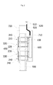
- FIG. 2 is a cross-sectional view of a fully assembled state of a control rod driver according to an embodiment of the present invention.
- FIG. 3 (a) is a plan view of a coil assembly having improved heat resistance for use in a control rod driver
- FIG. 3(b) is a cross-sectional view taken along line A-A of FIG. 3(a) .
- FIG. 4 is a cross-sectional view of a state in which a coil assembly having improved heat resistance for use in a control rod driver is combined with a coil housing according to an embodiment of the present invention.
- the control rod driver includes coil assemblies 100, 100-1, 100-2, 100-3, and 100-4, and first to fourth control rod driving coil units 310, 320, 330, and 340 in which the coil assembly 100 is mounted on inner circumferential surfaces thereof and that include coil housings 210, 220, 230, and 240 acting as a passage of an electromagnetic field induced when electric current is conducted through the coil assembly 100, respectively.
- An upper portion of the first control rod driving coil unit 310 and a lower portion of the fourth control rod driving coil unit 340 are combined with an upper plate 410 and a lower plate 420 each having a hole through which a motor housing 500 passes on a center portion thereof, respectively.
- the upper plate 410 functions not only as a passage of an electromagnetic field when electric current is conducted through the coil assembly 100 but also as a cover of an upper face of the first coil housing 210. Screw taps are formed on the upper plate 410 to recover an assembly of the coil housings 210, 220, 230, and 240.
- the lower plate 420 functions not only as a passage of an electromagnetic field when electric current is conducted through the coil assembly 100 but also as a cover of a lower face of the fourth coil housing 240, and supports all the control rod driving coil units 310 ,320, 330, and 340 when the motor housing 500 is assembled.
- An inner side of the coil assembly 100 mounted on the inner circumferential surfaces of the coil housings 210, 220, 230, and 240 is combined with the motor housing 500.
- a motor assembly (not shown) which is a control rod driver is installed.
- the motor housing 500 is designed to endure pressure of a nuclear reactor, and transmit an electromagnetic force applied from the coil assembly 100 combined with external surfaces of the motor housing 500.
- Lead wire connectors 211, 221, 231, and 241 in which both ends of coils of the respective coil assemblies 100-1, 100-2, 100-3, and 100-4 and a lead wire of a power supply cable 621 are united are formed at one side of the coil housings 210, 220, 230, and 240.
- the lead wire of the power supply cable 621 and both ends of the coils of the respective coil assemblies 100-1, 100-2, 100-3, and 100-4 are electrically connected to a connection terminal inside a cable box 610.
- both of the ends of the coils of the respective coil assemblies 100-1, 100-2, 100-3, and 100-4 and the lead wire of the power supply cable 621 may be united using brazing to minimize resistance therebetween.
- the power supply cable 621 and a connector 622 coupled to one end of the power supply cable 621 form a cable assembly 620 configured to supply power to coils.
- a cooling shroud 710 that guides cooled air to uniformly flow along the inside thereof is formed around the coil housings 210, 220, 230, and 240 to absorb heat generated by the coil assembly 100.
- An upper shroud 720 is formed on the coil housing 210, and a control rod location indicator (not shown) is installed in the upper shroud 720. The upper shroud 720 is combined with the coil housing 210 to recover the control rod driver.
- the motor housing 500, the cooling shroud 710, and the upper shroud 720 are not elements of the control rod driver, these elements have also been illustrated and described above to assist in understanding of the present invention.
- the coil assembly 100 for use in the control rod driver includes a coil wire 111, a polyether ether ketone (PEEK) coating layer 112 covering an outer circumferential surface of the coil wire 111, a covered wire 110 that includes the coil wire 111 and the PEEK coating layer 112 and is wound in multiple layers, a coil coating layer 130 formed by filling gaps in the covered wire 110 that is wound in multiple layers with varnish, an insulating tape layer 120 covering external sides of a wound layer of the covered wire 110 insulated by the coil coating layer 130, and a silicon molding 140 that seals the insulating tape layer 120 while encompassing external side surfaces of the insulating tape layer 120.
- PEEK polyether ether ketone
- the coil wire 111 may be formed of a copper wire that has no splices when it is wound to improve heat resistance more than that of a conventional coil for use in a control rod driver.
- a temperature at which the PEEK coating layer 112 covering the outer circumferential surface of the coil wires 111 can be continuously used is about 260 °C which is higher than a temperature at which the conventional enamel-based insulating material can be continuously used is about 220°C.
- the PEEK coating layer 112 greatly increases the heat resistance of coils.
- PEEK is a crystalline resin that can be dissolved and shaped in a desired form, has good chemical properties including high thermal resistance, fatigue resistance, chemical resistance, radiation resistance, a hard burning property by which it generates no corrosive gas and less smoke, and good mechanical properties including high strength, high coefficient of expansion, and high shock resistance. Also, PEEK is very strong at high temperature and tensile stress applied to PEEK is maintained constant even when it is used for a long time.
- the covered wire 110 is formed by covering the external surfaces of the coil wire 111 formed of copper wire having no splices with the PEEK coating layer 112.
- the coil assembly 100 configured to operate in a special high-temperature environment of a nuclear reactor may be prevented from deteriorating and being damaged beforehand.
- the insulating tape layer 120 is a heat-resistant glass fiber fabric, that fixes the shape of the wound layer of the covered wire 110 when external sides of the wound layer are covered with the insulating tape layer 120 and increases the adhesive properties of the silicon molding 140 applied onto the external sides of insulating tape layer 120.
- the coil coating layer 130 filled with the varnish is formed by vacuum impregnation.
- vacuum impregnation means a process of dipping the wound layer of the covered wire 110 whose shape is fixed by the insulating tape layer 120 into a tub containing an impregnation varnish solution, placing the tub in a vacuum chamber, and causing the tub to have a vacuum state so as to emit air and moisture present in gaps in the covered wire 110 to the outside due to the vacuum, thereby causing the varnish solution to impregnate into the gaps.
- impurities or air may be removed from the gaps in the covered wire 110 to increase a heat discharging effect and to maintain the shape of the coil assembly 100 after the coil coating layer 130 is dried to be hardened.
- the silicon molding 140 is a heat-resistant rubber wrapping material configured to completely encompass the external sides of the coil coating layer 130 after the coil coating layer 130 is dried to be hardened, and protects the coil coating layer 130 from foreign substances such as external moisture, dust, air, etc.
- the coil assembly 100 configured as described above is manufactured using the first to fourth coil assembles 100-1, 100-2, 100-3, and 100-4 having the same structure.
- the first to fourth coil assembles 100-1, 100-2, 100-3, and 100-4 are respectively installed in the first to fourth coil housings 210, 220, 230, and 240 to form the first to fourth control rod driving coil units 310, 320, 330, and 340.
- the control rod drive mechanism (motor assembly) is operated by an electromagnetic field formed by sequentially supplying current to the first to fourth control rod driving coil units 310, 320, 330, and 340, according to programming of a controller (not shown).
- the four coil housings 210, 220, 230, and 240 are connected by the connection plates 430, 440, 460, and 470 installed therebetween, and a housing connection member 450 is bound between the second coil housing 220 and the third coil housing 230 to maintain the distance between the second coil housing 220 and the third coil housing 230.
- the first coil housing 210, the second coil housing 220, the housing connection member 450, the third coil housing 230, and the fourth coil housing 240 are fixed to be engaged with one another by retainer couplings 431, 441, 461, and 471 disposed on external surfaces of the respective connection plate 430, 440, 460, and 470.
- FIG. 5 is a flowchart illustrating a method of manufacturing a coil assembly having improved heat resistance for use in a control rod driver according to an embodiment of the present invention.
- the method of manufacturing a coil assembly having improved heat resistance for use in a control rod driver includes manufacturing the covered wire 110 by forming the PEEK coating layer 112 on an outer circumferential surface of the coil wire 111, forming a wound layer by winding the covered wire 110 in multiple layers, binding both ends of the covered wire 110 with two pieces of a lead wire connected to the power supply cable 621, forming the insulating tape layer 120 around the wound layer of the covered wire 110, forming the coil coating layer 130 by filling the gaps in the covered wire 110 with varnish, drying the coil coating layer 130 in a drying furnace, and applying the silicon molding 140 onto an outer circumferential surface of the dried resultant.
- the binding of both of the ends of the covered wire 110 with the two pieces of the lead wire connected to the power supply cable 621 is performed using brazing to minimize resistance at the interfaces between both of the ends of the covered wire 110 and the two pieces of the lead wire connected to the power supply cable 621.
- the forming of the coil coating layer 130 may be performed by vacuum impregnation.
- the heat resistance of the coil assembly may be improved and insulating properties between covered wires may be improved by vacuum impregnation.
- coils may be prevented beforehand from deteriorating or being damaged due to heat generation and insulation breakdown caused when electric charge is conducted through coils during driving of the control rod driver, thereby preventing the fall of a control rod.
Landscapes
- Engineering & Computer Science (AREA)
- Physics & Mathematics (AREA)
- Power Engineering (AREA)
- Plasma & Fusion (AREA)
- High Energy & Nuclear Physics (AREA)
- General Engineering & Computer Science (AREA)
- Manufacturing & Machinery (AREA)
- Chemical Kinetics & Catalysis (AREA)
- Chemical & Material Sciences (AREA)
- Theoretical Computer Science (AREA)
- General Physics & Mathematics (AREA)
- Insulation, Fastening Of Motor, Generator Windings (AREA)
- Manufacture Of Motors, Generators (AREA)
- Media Introduction/Drainage Providing Device (AREA)
- Resistance Heating (AREA)
Abstract
Description
- The present invention relates to a coil assembly for a control rod driver for driving a nuclear power plant and a method for manufacturing the same, and more particularly, to a coil assembly for a control rod driver having improved thermal resistance in which coil deterioration is reduced by improving the heat resistance and thermal conductivity of coils to securely prevent coil deterioration and the fall of a control rod, caused by continuous operations of the control rod driver during an automatic load follow operation, thereby improving the safety and economic feasibility of a nuclear power plant, and a method for manufacturing the same.
- A nuclear reactor is a device designed to gradually discharge a large amount of energy that is instantaneously emitted due to a mass defect occurring during nuclear fission of a nuclear fuel, thereby enabling nuclear energy to be applied to real life.
-
FIG. 1 is a cross-sectional view of a conventional nuclear reactor and a control rod driver. - A fuel assembly 2 is accommodated in the
nuclear reactor 1. An assembly of a control rod 3 and a control roddriver attaching nozzle 4 that are configured to adjust the number of neutrons absorbed by nuclear fuel so as to control the combustion of the nuclear fuel, and a plurality of control rod driver 5 including control rod driving motors are installed on upper part of thenuclear reactor 1. The control rod 3 is vertically driven by the control rod driver 5. - The control rod driver is operated by a current signal flowing through four control rod driving coils, i.e., an upper lift coil (UL), an upper gripper coil (UG), a lower lift coil (LL), and a lower gripper coil (LG), and are configured to control the vertical movement of the control rod 3 by controlling motor driving using an electromagnetic force generated by power supplied to cables of the control rod driving coils.
- The control rod driving coils used in the control rod driver 5 are required to have heat resistance so that the control rod driving coils may be prevented from deteriorating due to continuous operations of the control rod driver 5 during an automatic load follow operation. However, since coil wires are conventionally covered with an enamel-based insulating material, the coils deteriorate at a temperature that is higher than 220 °C to stop electricity generation. Thus, power generation is stopped until the system is re-operated, electric current is conducted through the coils due to the deterioration of and damage to the coils, and insulation breakdown thus occurs, causing the fall of the control rod and thereby degrading safety and reliability.
- It is an objective of the present invention to provide a coil assembly for use in a control rod driver, in which the heat resistance of control rod driving coils is improved to increase the lifespan thereof and the deterioration of the coils and the fall of a control rod are thus securely prevented due to continuous operations of the control rod driver during an automatic load follow operation, thereby improving the safety and economic feasibility of a nuclear power plant, and a method of manufacturing the same.
- To accomplish the objective, a coil assembly having improved heat resistance for use in a control rod driver includes a covered wire including a coil wire and a polyether ether ketone (PEEK) coating layer covering an outer circumferential surface of the coil wire, and wound in multiple layers; a coil coating layer formed by filling gaps in the covered wire with varnish; an insulating tape layer covering external sides of a wound layer of the covered wire insulated by the coil coating layer; and silicon molding covering external sides of the insulating tape layer.
- The coil wire may be a copper wire having no splices.
- Both ends of the coil wire may be bound with a lead wire of a power supply cable by brazing.
- To accomplish the objective, a method of manufacturing a coil assembly having improved heat resistance for use in a control rod driver includes manufacturing a covered wire by forming a polyether ether ketone (PEEK) coating layer on an outer circumferential surface of a coil wire; forming a wound layer by winding the covered wire in multiple layers, and binding both ends of the coil wire with a lead wire of a power supply cable; forming an insulating tape layer around the wound layer; forming a coil coating layer by filling gaps in the covered wire with varnish; drying the coil coating layer in a drying furnace; and applying silicon molding on an outer circumferential surface of the dried resultant.
- The forming of the coil coating layer may be performed by vacuum impregnation.
- In a coil assembly having improved heat resistance for use in a control rod driver and a method for manufacturing the same, the coil assembly is manufactured by forming a covered wire by covering an outer circumferential surface of a coil wire with a polyether ether ketone (PEEK) coating layer having chemical and mechanical characteristics such as heat resistance, forming a coil coating layer by filling gaps in the covered wire that is wound in multiple layers with varnish by vacuum impregnation, and sealing an outer circumferential surface of the coil coating layer with silicon molding. Thus, the coil assembly has higher heat resistance and lifespan than a conventional coil for use in a control rod driver, and greatly reduces coil deterioration and the fall of a control rod due to continuous operations of a control rod driver during an automatic load follow operation, thereby improving the safety and economic feasibility of a nuclear power plant.
-
-
FIG. 1 is a cross-sectional view of a conventional nuclear reactor and a control rod driver. -
FIG. 2 is a cross-sectional view of a fully assembled state of a control rod driver according to an embodiment of the present invention. -
FIG. 3(a) is a plan view of a coil assembly having improved heat resistance for use in a control rod driver, andFIG. 3(b) is a cross-sectional view taken along line A-A ofFIG. 3(a) . -
FIG. 4 is a cross-sectional view of a state in which a coil assembly having improved heat resistance for use in a control rod driver is combined with a coil housing according to an embodiment of the present invention. -
FIG. 5 is a flowchart illustrating a method of manufacturing a coil assembly having improved heat resistance for use in a control rod driver according to an embodiment of the present invention. -
1: nuclear reactor 2: nuclear fuel assembly 3: control rod nozzle 4: control rod driver attaching 5: control rod driver 100, 100-1, 100-2, 100-3, and 100-4: coil assembly 110: covered wire 111: coil wire 112: PEEK coating layer 120: insulating tape layer 130: coil coating layer 140: silicon molding 210, 220, 230, 240: coil housing 211, 221, 231, 241: lead wire connector 310: the first control rod driving coil unit 320: the second control rod driving coil unit 330: the third control rod driving coil unit 340: the fourth control rod driving coil unit 410: upper plate 420: lower plate 430, 440, 460, 470: connection plate 450: housing connection member 431, 441, 461, 471: retainer coupling 500: motor housing 610: cable box 620: cable assembly 621: power supply cable 622: connector 710: cooling shroud 720: upper shroud - Hereinafter, structures and operations of exemplary embodiments of the present invention will be described in greater detail with reference to the accompanying drawings.
-
FIG. 2 is a cross-sectional view of a fully assembled state of a control rod driver according to an embodiment of the present invention.FIG. 3 (a) is a plan view of a coil assembly having improved heat resistance for use in a control rod driver, andFIG. 3(b) is a cross-sectional view taken along line A-A ofFIG. 3(a) .FIG. 4 is a cross-sectional view of a state in which a coil assembly having improved heat resistance for use in a control rod driver is combined with a coil housing according to an embodiment of the present invention. - Referring to
FIG. 2 , the control rod driver according to the present invention includescoil assemblies 100, 100-1, 100-2, 100-3, and 100-4, and first to fourth control roddriving coil units coil assembly 100 is mounted on inner circumferential surfaces thereof and that includecoil housings coil assembly 100, respectively. An upper portion of the first control roddriving coil unit 310 and a lower portion of the fourth control roddriving coil unit 340 are combined with anupper plate 410 and alower plate 420 each having a hole through which amotor housing 500 passes on a center portion thereof, respectively. - The
upper plate 410 functions not only as a passage of an electromagnetic field when electric current is conducted through thecoil assembly 100 but also as a cover of an upper face of thefirst coil housing 210. Screw taps are formed on theupper plate 410 to recover an assembly of thecoil housings - The
lower plate 420 functions not only as a passage of an electromagnetic field when electric current is conducted through thecoil assembly 100 but also as a cover of a lower face of thefourth coil housing 240, and supports all the control roddriving coil units motor housing 500 is assembled. - An inner side of the
coil assembly 100 mounted on the inner circumferential surfaces of thecoil housings motor housing 500. In themotor housing 500, a motor assembly (not shown) which is a control rod driver is installed. Thus, themotor housing 500 is designed to endure pressure of a nuclear reactor, and transmit an electromagnetic force applied from thecoil assembly 100 combined with external surfaces of themotor housing 500. -
Lead wire connectors power supply cable 621 are united are formed at one side of thecoil housings power supply cable 621 and both ends of the coils of the respective coil assemblies 100-1, 100-2, 100-3, and 100-4 are electrically connected to a connection terminal inside acable box 610. - It is desired that both of the ends of the coils of the respective coil assemblies 100-1, 100-2, 100-3, and 100-4 and the lead wire of the
power supply cable 621 may be united using brazing to minimize resistance therebetween. - The
power supply cable 621 and aconnector 622 coupled to one end of thepower supply cable 621 form acable assembly 620 configured to supply power to coils. - A
cooling shroud 710 that guides cooled air to uniformly flow along the inside thereof is formed around thecoil housings coil assembly 100. Anupper shroud 720 is formed on thecoil housing 210, and a control rod location indicator (not shown) is installed in theupper shroud 720. Theupper shroud 720 is combined with thecoil housing 210 to recover the control rod driver. - Here, although the
motor housing 500, thecooling shroud 710, and theupper shroud 720 are not elements of the control rod driver, these elements have also been illustrated and described above to assist in understanding of the present invention. - Referring to
FIG. 3 , thecoil assembly 100 for use in the control rod driver includes acoil wire 111, a polyether ether ketone (PEEK)coating layer 112 covering an outer circumferential surface of thecoil wire 111, a coveredwire 110 that includes thecoil wire 111 and thePEEK coating layer 112 and is wound in multiple layers, acoil coating layer 130 formed by filling gaps in the coveredwire 110 that is wound in multiple layers with varnish, aninsulating tape layer 120 covering external sides of a wound layer of the coveredwire 110 insulated by thecoil coating layer 130, and asilicon molding 140 that seals theinsulating tape layer 120 while encompassing external side surfaces of theinsulating tape layer 120. - The
coil wire 111 may be formed of a copper wire that has no splices when it is wound to improve heat resistance more than that of a conventional coil for use in a control rod driver. - A temperature at which the
PEEK coating layer 112 covering the outer circumferential surface of thecoil wires 111 can be continuously used is about 260 °C which is higher than a temperature at which the conventional enamel-based insulating material can be continuously used is about 220°C. Thus, thePEEK coating layer 112 greatly increases the heat resistance of coils. - PEEK is a crystalline resin that can be dissolved and shaped in a desired form, has good chemical properties including high thermal resistance, fatigue resistance, chemical resistance, radiation resistance, a hard burning property by which it generates no corrosive gas and less smoke, and good mechanical properties including high strength, high coefficient of expansion, and high shock resistance. Also, PEEK is very strong at high temperature and tensile stress applied to PEEK is maintained constant even when it is used for a long time.
- According to the present invention, the covered
wire 110 is formed by covering the external surfaces of thecoil wire 111 formed of copper wire having no splices with thePEEK coating layer 112. Thus, thecoil assembly 100 configured to operate in a special high-temperature environment of a nuclear reactor may be prevented from deteriorating and being damaged beforehand. - The
insulating tape layer 120 is a heat-resistant glass fiber fabric, that fixes the shape of the wound layer of the coveredwire 110 when external sides of the wound layer are covered with theinsulating tape layer 120 and increases the adhesive properties of thesilicon molding 140 applied onto the external sides ofinsulating tape layer 120. - The
coil coating layer 130 filled with the varnish is formed by vacuum impregnation. Here, vacuum impregnation means a process of dipping the wound layer of the coveredwire 110 whose shape is fixed by theinsulating tape layer 120 into a tub containing an impregnation varnish solution, placing the tub in a vacuum chamber, and causing the tub to have a vacuum state so as to emit air and moisture present in gaps in the coveredwire 110 to the outside due to the vacuum, thereby causing the varnish solution to impregnate into the gaps. - By forming the
coil coating layer 130, impurities or air may be removed from the gaps in the coveredwire 110 to increase a heat discharging effect and to maintain the shape of thecoil assembly 100 after thecoil coating layer 130 is dried to be hardened. - The
silicon molding 140 is a heat-resistant rubber wrapping material configured to completely encompass the external sides of thecoil coating layer 130 after thecoil coating layer 130 is dried to be hardened, and protects thecoil coating layer 130 from foreign substances such as external moisture, dust, air, etc. - Referring to
FIG. 4 , thecoil assembly 100 configured as described above is manufactured using the first to fourth coil assembles 100-1, 100-2, 100-3, and 100-4 having the same structure. The first to fourth coil assembles 100-1, 100-2, 100-3, and 100-4 are respectively installed in the first tofourth coil housings coil units coil units - The four
coil housings connection plates housing connection member 450 is bound between thesecond coil housing 220 and thethird coil housing 230 to maintain the distance between thesecond coil housing 220 and thethird coil housing 230. - The
first coil housing 210, thesecond coil housing 220, thehousing connection member 450, thethird coil housing 230, and thefourth coil housing 240 are fixed to be engaged with one another byretainer couplings respective connection plate -
FIG. 5 is a flowchart illustrating a method of manufacturing a coil assembly having improved heat resistance for use in a control rod driver according to an embodiment of the present invention. - The method of manufacturing a coil assembly having improved heat resistance for use in a control rod driver according to an embodiment of the present invention includes manufacturing the covered
wire 110 by forming thePEEK coating layer 112 on an outer circumferential surface of thecoil wire 111, forming a wound layer by winding the coveredwire 110 in multiple layers, binding both ends of the coveredwire 110 with two pieces of a lead wire connected to thepower supply cable 621, forming the insulatingtape layer 120 around the wound layer of the coveredwire 110, forming thecoil coating layer 130 by filling the gaps in the coveredwire 110 with varnish, drying thecoil coating layer 130 in a drying furnace, and applying thesilicon molding 140 onto an outer circumferential surface of the dried resultant. - It is desired that the binding of both of the ends of the covered
wire 110 with the two pieces of the lead wire connected to thepower supply cable 621 is performed using brazing to minimize resistance at the interfaces between both of the ends of the coveredwire 110 and the two pieces of the lead wire connected to thepower supply cable 621. The forming of thecoil coating layer 130 may be performed by vacuum impregnation. - As described above, in a coil assembly having improved heat resistance for use in a control rod driver and a method for manufacturing the same according to the present invention, the heat resistance of the coil assembly may be improved and insulating properties between covered wires may be improved by vacuum impregnation. Thus, coils may be prevented beforehand from deteriorating or being damaged due to heat generation and insulation breakdown caused when electric charge is conducted through coils during driving of the control rod driver, thereby preventing the fall of a control rod.
Claims (5)
- A coil assembly having improved heat resistance for use in a control rod driver, comprising:a covered wire (110) including a coil wire (111) and a polyether ether ketone (PEEK) coating layer (112) covering an outer circumferential surface of the coil wire (111), and wound in multiple layers;a coil coating layer (130) formed by filling gaps in the covered wire (110) with varnish;an insulating tape layer (120) covering external sides of a wound layer of the covered wire (110) insulated by the coil coating layer (130); andsilicon molding (140) covering external sides of the insulating tape layer (120).
- The coil assembly of claim 1, wherein the coil wire (111) is a copper wire having no splices.
- The coil assembly of claim 1 or 2, wherein both ends of the coil wire (111) are bound with a lead wire of a power supply cable (621) by brazing.
- A method for manufacturing a coil assembly having improved heat resistance for use in a control rod driver, the method comprising:manufacturing a covered wire (110) by forming a polyether ether ketone (PEEK) coating layer (112) on an outer circumferential surface of a coil wire (111);forming a wound layer by winding the covered wire (110) in multiple layers, and binding both ends of the coil wire (111) with a lead wire of a power supply cable (621);forming an insulating tape layer (120) around the wound layer;forming a coil coating layer (130) by filling gaps in the covered wire (110) with varnish;drying the coil coating layer (130) in a drying furnace; andapplying silicon molding (140) on an outer circumferential surface of the dried resultant.
- The method of claim 4, wherein the forming of the coil coating layer (130) is performed by vacuum impregnation.
Priority Applications (1)
| Application Number | Priority Date | Filing Date | Title |
|---|---|---|---|
| PL11856834T PL2669896T3 (en) | 2011-01-27 | 2011-02-01 | Coil assembly for a control rod driver having improved thermal resistance, and method for manufacturing same |
Applications Claiming Priority (2)
| Application Number | Priority Date | Filing Date | Title |
|---|---|---|---|
| KR1020110008242A KR101189924B1 (en) | 2011-01-27 | 2011-01-27 | Coil assembly having improved heat-resistance for control element drive mechanism and manufacturing method of the coil assembly |
| PCT/KR2011/000690 WO2012102430A1 (en) | 2011-01-27 | 2011-02-01 | Coil assembly for a control rod driver having improved thermal resistance, and method for manufacturing same |
Publications (3)
| Publication Number | Publication Date |
|---|---|
| EP2669896A1 true EP2669896A1 (en) | 2013-12-04 |
| EP2669896A4 EP2669896A4 (en) | 2017-05-10 |
| EP2669896B1 EP2669896B1 (en) | 2018-08-15 |
Family
ID=46580988
Family Applications (1)
| Application Number | Title | Priority Date | Filing Date |
|---|---|---|---|
| EP11856834.4A Active EP2669896B1 (en) | 2011-01-27 | 2011-02-01 | Coil assembly for a control rod driver having improved thermal resistance, and method for manufacturing same |
Country Status (6)
| Country | Link |
|---|---|
| US (1) | US9564265B2 (en) |
| EP (1) | EP2669896B1 (en) |
| KR (1) | KR101189924B1 (en) |
| CN (1) | CN103329209B (en) |
| PL (1) | PL2669896T3 (en) |
| WO (1) | WO2012102430A1 (en) |
Cited By (1)
| Publication number | Priority date | Publication date | Assignee | Title |
|---|---|---|---|---|
| WO2016092087A1 (en) * | 2014-12-12 | 2016-06-16 | Solvay Specialty Polymers Usa, Llc | Poly(aryl ether) compositions for polymer-metal junctions and polymer-metal junctions and corresponding fabrication methods |
Families Citing this family (16)
| Publication number | Priority date | Publication date | Assignee | Title |
|---|---|---|---|---|
| CN103871726B (en) * | 2012-12-11 | 2016-08-03 | 中国核动力研究设计院 | A kind of control coil manufacturing process being applicable to CRDM |
| KR101553020B1 (en) | 2014-05-30 | 2015-09-14 | 한국전력기술 주식회사 | Magnetic Jack Type In-Vessel Control Element Drive Mechanism |
| KR101599003B1 (en) | 2014-11-13 | 2016-03-02 | 한국전력기술 주식회사 | Magnetic Jack Type Control Element Drive Mechanism for Precision Position Control of the Control Element Assembly |
| CN113299410A (en) | 2015-04-10 | 2021-08-24 | 芙罗服务管理公司 | Method for operating a nuclear reactor and valve actuator for use on a valve of a fluid system of a nuclear reactor |
| KR101693785B1 (en) | 2015-07-06 | 2017-01-06 | 한국전력기술 주식회사 | Control Element Drive Mechanism using ring shape ratchet |
| CN106782993B (en) * | 2016-11-24 | 2018-07-20 | 中广核工程有限公司 | Control rod drive mechanism and its coil component |
| WO2018121493A1 (en) * | 2016-12-28 | 2018-07-05 | 东丽先端材料研究开发(中国)有限公司 | Resin composition for bonding metal, product formed by bonding metal with resin composition, and manufacturing method |
| CN108257761B (en) * | 2018-01-16 | 2023-11-28 | 喻杰 | Control rod driving mechanism electromagnetic coil assembly and manufacturing method thereof |
| CN108231370A (en) * | 2018-01-23 | 2018-06-29 | 上海第机床厂有限公司 | Presurized water reactor control rod drive mechanism yoke coil device and its assembly method |
| US20190252101A1 (en) * | 2018-02-14 | 2019-08-15 | G.W. Lisk Company, Inc. | Method and apparatus for electromagnetic wound coil |
| US11309095B2 (en) * | 2019-03-28 | 2022-04-19 | BWXT Advanced Technologies LLC | Control rod drive mechanism with separate latch and drive coils |
| DE102019109511B4 (en) * | 2019-04-10 | 2021-01-14 | Vem Sachsenwerk Gmbh | Climatic-proof solenoid |
| KR102187262B1 (en) | 2019-04-25 | 2020-12-04 | 한국전력기술 주식회사 | Control Element Drive Mechanism with Interrior permanent magnet |
| CN114709072B (en) * | 2019-08-31 | 2024-04-02 | 深圳硅基仿生科技股份有限公司 | Winding device for planar coil |
| GB2590097A (en) * | 2020-07-21 | 2021-06-23 | Rolls Royce Plc | Nuclear reactor and method of opening a nuclear reactor |
| KR102433937B1 (en) | 2021-08-24 | 2022-08-19 | 주식회사 넥시스 | FPGA-based DC power reactor control rod driving device control system and its control method |
Family Cites Families (19)
| Publication number | Priority date | Publication date | Assignee | Title |
|---|---|---|---|---|
| US6685696B2 (en) * | 1987-09-30 | 2004-02-03 | Lake Region Manufacturing, Inc. | Hollow lumen cable apparatus |
| JPH0260451A (en) * | 1988-08-26 | 1990-02-28 | Canon Inc | linear motor device |
| JPH02270210A (en) * | 1989-04-10 | 1990-11-05 | Fujikura Ltd | Insulated wire |
| EP0712139A3 (en) * | 1990-01-31 | 1998-03-25 | Fujikura Ltd. | Electric insulated wire and cable using the same |
| JP3150349B2 (en) * | 1991-01-30 | 2001-03-26 | 株式会社東芝 | Manufacturing method of heat-resistant insulated wire |
| JP2784304B2 (en) * | 1992-11-13 | 1998-08-06 | 日本原子力研究所 | Control rod for high temperature gas furnace made of carbon composite material and method of manufacturing the same |
| JP3444941B2 (en) * | 1993-11-04 | 2003-09-08 | 株式会社東芝 | Heat-resistant and radiation-resistant cable and furnace internal structure inspection device for fast breeder reactor using the same |
| EP0823767A1 (en) * | 1996-08-07 | 1998-02-11 | SUMITOMO WIRING SYSTEMS, Ltd. | Charging system for electric vehicle |
| JP2000340039A (en) * | 1999-05-26 | 2000-12-08 | Norichika Takebe | Insulation reinforcement litz wire and its manufacture |
| US6319604B1 (en) * | 1999-07-08 | 2001-11-20 | Phelps Dodge Industries, Inc. | Abrasion resistant coated wire |
| CN2442364Y (en) * | 2000-09-14 | 2001-08-08 | 上海电机(集团)公司先锋电机厂 | Insulation encapsulated coil |
| US7113068B2 (en) * | 2001-07-06 | 2006-09-26 | Chin-Kuo Chou | Winding structure of inductor used in power factor correction circuit |
| JP4000382B2 (en) * | 2002-10-09 | 2007-10-31 | 独立行政法人 日本原子力研究開発機構 | Control rod made of boron mixed carbon fiber reinforced carbon composite material |
| CN1499537A (en) * | 2002-11-05 | 2004-05-26 | 新疆特变电工股份有限公司 | High temperature and vapor resistant insulated wire as well as manufacturing method |
| JP2008053463A (en) | 2006-08-24 | 2008-03-06 | Nidec-Read Corp | Substrate-holding apparatus |
| FR2944393B1 (en) * | 2009-04-09 | 2014-10-17 | Converteam Technology Ltd | COIL FOR A ROTATING ELECTRIC MACHINE |
| US8081415B2 (en) * | 2009-04-16 | 2011-12-20 | Paige Electric Company, L.P. | Grounding assembly |
| KR100957017B1 (en) * | 2009-10-30 | 2010-05-13 | (주)에치케이일렉트 | Coil assembly for driving mechanism of control element and method for manufacturing of as the same |
| KR20110060133A (en) * | 2009-11-30 | 2011-06-08 | 엘에스전선 주식회사 | Nuclear power generation cable with improved lifespan and its manufacturing method |
-
2011
- 2011-01-27 KR KR1020110008242A patent/KR101189924B1/en active Active
- 2011-02-01 PL PL11856834T patent/PL2669896T3/en unknown
- 2011-02-01 WO PCT/KR2011/000690 patent/WO2012102430A1/en not_active Ceased
- 2011-02-01 CN CN201180066153.0A patent/CN103329209B/en active Active
- 2011-02-01 EP EP11856834.4A patent/EP2669896B1/en active Active
-
2013
- 2013-07-25 US US13/950,943 patent/US9564265B2/en active Active
Non-Patent Citations (1)
| Title |
|---|
| See references of WO2012102430A1 * |
Cited By (2)
| Publication number | Priority date | Publication date | Assignee | Title |
|---|---|---|---|---|
| WO2016092087A1 (en) * | 2014-12-12 | 2016-06-16 | Solvay Specialty Polymers Usa, Llc | Poly(aryl ether) compositions for polymer-metal junctions and polymer-metal junctions and corresponding fabrication methods |
| US10519277B2 (en) | 2014-12-12 | 2019-12-31 | Solvay Specialty Polymers Usa, Llc | Poly(aryl ether) compositions for polymer-metal junctions and polymer-metal junctions and corresponding fabrication methods |
Also Published As
| Publication number | Publication date |
|---|---|
| CN103329209B (en) | 2017-03-08 |
| KR20120086904A (en) | 2012-08-06 |
| EP2669896B1 (en) | 2018-08-15 |
| US9564265B2 (en) | 2017-02-07 |
| US20130335181A1 (en) | 2013-12-19 |
| WO2012102430A1 (en) | 2012-08-02 |
| CN103329209A (en) | 2013-09-25 |
| KR101189924B1 (en) | 2012-10-15 |
| EP2669896A4 (en) | 2017-05-10 |
| PL2669896T3 (en) | 2019-01-31 |
Similar Documents
| Publication | Publication Date | Title |
|---|---|---|
| US9564265B2 (en) | Coil assembly for a control rod driver having improved thermal resistance, and method for manufacturing the same | |
| US8402636B2 (en) | Method of manufacturing ground-burial type solid insulated transformer | |
| CN101854090A (en) | Reduction insulation structure suitable for high-voltage motor and insulation processing method thereof | |
| KR101412734B1 (en) | Current connection apparatus for tanks | |
| US9722464B2 (en) | Gas turbine engine actuation systems including high temperature actuators and methods for the manufacture thereof | |
| CN104600959B (en) | A kind of motor stator being applied under liquid hydrogen environment | |
| US9208926B2 (en) | Active cooling of medium voltage power umbilicals | |
| CN113270224B (en) | High-voltage-resistant superconducting cable potential detection wire insulation leading-out structure | |
| CN1260574A (en) | Insulation structure of electric equipment coil and manufacturing method thereof | |
| EP2434619A2 (en) | Arrangement of conducting bar ends | |
| CN102103905B (en) | Defect eliminating method for main insulation of cold insulation superconducting cable and system structure for realizing method | |
| US20200194172A1 (en) | Reactor and Respective Manufacturing Method | |
| WO2014173497A1 (en) | Coil assembly for a dry transformer; method for manufacturing a coil assembly and dry transformer | |
| KR100758976B1 (en) | Manufacturing method of electromagnet coil by vacuum impregnation of thermosetting resin mixture containing low viscosity epoxy | |
| Nakamoto et al. | Development of gap-filling impregnation method of ITER TF coils | |
| CN110993250A (en) | High temperature resistant electromagnetic coil for control rod drive mechanism of nuclear power plant | |
| CN104200983A (en) | Method for manufacturing vacuum special-shaped deflection magnet with four internal channels | |
| KR101426342B1 (en) | Mold type shunt reactor | |
| Bossert et al. | Construction experience with MQXB quadrupole magnets built at Fermilab for the LHC interaction regions | |
| CN122025384A (en) | Transformer coil and manufacturing method thereof | |
| CN104900327B (en) | The manufacture method of integral type dry type insulating tube type busbar | |
| Milani et al. | DC busbars for the ITER power supply system: Features and challenges | |
| KR102964109B1 (en) | Winding bodies, high-voltage windings, and dry-type transformers | |
| CN220672375U (en) | High-voltage winding | |
| CN209947512U (en) | Corrosion-resistant motor connecting wire |
Legal Events
| Date | Code | Title | Description |
|---|---|---|---|
| PUAI | Public reference made under article 153(3) epc to a published international application that has entered the european phase |
Free format text: ORIGINAL CODE: 0009012 |
|
| 17P | Request for examination filed |
Effective date: 20130712 |
|
| AK | Designated contracting states |
Kind code of ref document: A1 Designated state(s): AL AT BE BG CH CY CZ DE DK EE ES FI FR GB GR HR HU IE IS IT LI LT LU LV MC MK MT NL NO PL PT RO RS SE SI SK SM TR |
|
| DAX | Request for extension of the european patent (deleted) | ||
| RA4 | Supplementary search report drawn up and despatched (corrected) |
Effective date: 20170412 |
|
| RIC1 | Information provided on ipc code assigned before grant |
Ipc: G21C 7/10 20060101AFI20170406BHEP Ipc: G21C 21/18 20060101ALI20170406BHEP Ipc: H01F 5/06 20060101ALI20170406BHEP Ipc: H01F 41/12 20060101ALI20170406BHEP Ipc: H01F 27/32 20060101ALI20170406BHEP Ipc: G21C 7/12 20060101ALI20170406BHEP |
|
| GRAP | Despatch of communication of intention to grant a patent |
Free format text: ORIGINAL CODE: EPIDOSNIGR1 |
|
| STAA | Information on the status of an ep patent application or granted ep patent |
Free format text: STATUS: GRANT OF PATENT IS INTENDED |
|
| INTG | Intention to grant announced |
Effective date: 20180312 |
|
| GRAS | Grant fee paid |
Free format text: ORIGINAL CODE: EPIDOSNIGR3 |
|
| GRAA | (expected) grant |
Free format text: ORIGINAL CODE: 0009210 |
|
| STAA | Information on the status of an ep patent application or granted ep patent |
Free format text: STATUS: THE PATENT HAS BEEN GRANTED |
|
| AK | Designated contracting states |
Kind code of ref document: B1 Designated state(s): AL AT BE BG CH CY CZ DE DK EE ES FI FR GB GR HR HU IE IS IT LI LT LU LV MC MK MT NL NO PL PT RO RS SE SI SK SM TR |
|
| REG | Reference to a national code |
Ref country code: CH Ref legal event code: EP Ref country code: GB Ref legal event code: FG4D Ref country code: AT Ref legal event code: REF Ref document number: 1030694 Country of ref document: AT Kind code of ref document: T Effective date: 20180815 |
|
| REG | Reference to a national code |
Ref country code: IE Ref legal event code: FG4D |
|
| REG | Reference to a national code |
Ref country code: DE Ref legal event code: R096 Ref document number: 602011051187 Country of ref document: DE |
|
| REG | Reference to a national code |
Ref country code: NL Ref legal event code: MP Effective date: 20180815 |
|
| REG | Reference to a national code |
Ref country code: LT Ref legal event code: MG4D |
|
| REG | Reference to a national code |
Ref country code: AT Ref legal event code: MK05 Ref document number: 1030694 Country of ref document: AT Kind code of ref document: T Effective date: 20180815 |
|
| PG25 | Lapsed in a contracting state [announced via postgrant information from national office to epo] |
Ref country code: SE Free format text: LAPSE BECAUSE OF FAILURE TO SUBMIT A TRANSLATION OF THE DESCRIPTION OR TO PAY THE FEE WITHIN THE PRESCRIBED TIME-LIMIT Effective date: 20180815 Ref country code: LT Free format text: LAPSE BECAUSE OF FAILURE TO SUBMIT A TRANSLATION OF THE DESCRIPTION OR TO PAY THE FEE WITHIN THE PRESCRIBED TIME-LIMIT Effective date: 20180815 Ref country code: RS Free format text: LAPSE BECAUSE OF FAILURE TO SUBMIT A TRANSLATION OF THE DESCRIPTION OR TO PAY THE FEE WITHIN THE PRESCRIBED TIME-LIMIT Effective date: 20180815 Ref country code: NL Free format text: LAPSE BECAUSE OF FAILURE TO SUBMIT A TRANSLATION OF THE DESCRIPTION OR TO PAY THE FEE WITHIN THE PRESCRIBED TIME-LIMIT Effective date: 20180815 Ref country code: BG Free format text: LAPSE BECAUSE OF FAILURE TO SUBMIT A TRANSLATION OF THE DESCRIPTION OR TO PAY THE FEE WITHIN THE PRESCRIBED TIME-LIMIT Effective date: 20181115 Ref country code: NO Free format text: LAPSE BECAUSE OF FAILURE TO SUBMIT A TRANSLATION OF THE DESCRIPTION OR TO PAY THE FEE WITHIN THE PRESCRIBED TIME-LIMIT Effective date: 20181115 Ref country code: GR Free format text: LAPSE BECAUSE OF FAILURE TO SUBMIT A TRANSLATION OF THE DESCRIPTION OR TO PAY THE FEE WITHIN THE PRESCRIBED TIME-LIMIT Effective date: 20181116 Ref country code: AT Free format text: LAPSE BECAUSE OF FAILURE TO SUBMIT A TRANSLATION OF THE DESCRIPTION OR TO PAY THE FEE WITHIN THE PRESCRIBED TIME-LIMIT Effective date: 20180815 Ref country code: IS Free format text: LAPSE BECAUSE OF FAILURE TO SUBMIT A TRANSLATION OF THE DESCRIPTION OR TO PAY THE FEE WITHIN THE PRESCRIBED TIME-LIMIT Effective date: 20181215 |
|
| PG25 | Lapsed in a contracting state [announced via postgrant information from national office to epo] |
Ref country code: AL Free format text: LAPSE BECAUSE OF FAILURE TO SUBMIT A TRANSLATION OF THE DESCRIPTION OR TO PAY THE FEE WITHIN THE PRESCRIBED TIME-LIMIT Effective date: 20180815 Ref country code: HR Free format text: LAPSE BECAUSE OF FAILURE TO SUBMIT A TRANSLATION OF THE DESCRIPTION OR TO PAY THE FEE WITHIN THE PRESCRIBED TIME-LIMIT Effective date: 20180815 Ref country code: LV Free format text: LAPSE BECAUSE OF FAILURE TO SUBMIT A TRANSLATION OF THE DESCRIPTION OR TO PAY THE FEE WITHIN THE PRESCRIBED TIME-LIMIT Effective date: 20180815 |
|
| PG25 | Lapsed in a contracting state [announced via postgrant information from national office to epo] |
Ref country code: ES Free format text: LAPSE BECAUSE OF FAILURE TO SUBMIT A TRANSLATION OF THE DESCRIPTION OR TO PAY THE FEE WITHIN THE PRESCRIBED TIME-LIMIT Effective date: 20180815 Ref country code: EE Free format text: LAPSE BECAUSE OF FAILURE TO SUBMIT A TRANSLATION OF THE DESCRIPTION OR TO PAY THE FEE WITHIN THE PRESCRIBED TIME-LIMIT Effective date: 20180815 Ref country code: RO Free format text: LAPSE BECAUSE OF FAILURE TO SUBMIT A TRANSLATION OF THE DESCRIPTION OR TO PAY THE FEE WITHIN THE PRESCRIBED TIME-LIMIT Effective date: 20180815 Ref country code: IT Free format text: LAPSE BECAUSE OF FAILURE TO SUBMIT A TRANSLATION OF THE DESCRIPTION OR TO PAY THE FEE WITHIN THE PRESCRIBED TIME-LIMIT Effective date: 20180815 |
|
| REG | Reference to a national code |
Ref country code: DE Ref legal event code: R097 Ref document number: 602011051187 Country of ref document: DE |
|
| PG25 | Lapsed in a contracting state [announced via postgrant information from national office to epo] |
Ref country code: SK Free format text: LAPSE BECAUSE OF FAILURE TO SUBMIT A TRANSLATION OF THE DESCRIPTION OR TO PAY THE FEE WITHIN THE PRESCRIBED TIME-LIMIT Effective date: 20180815 Ref country code: DK Free format text: LAPSE BECAUSE OF FAILURE TO SUBMIT A TRANSLATION OF THE DESCRIPTION OR TO PAY THE FEE WITHIN THE PRESCRIBED TIME-LIMIT Effective date: 20180815 Ref country code: SM Free format text: LAPSE BECAUSE OF FAILURE TO SUBMIT A TRANSLATION OF THE DESCRIPTION OR TO PAY THE FEE WITHIN THE PRESCRIBED TIME-LIMIT Effective date: 20180815 |
|
| PLBE | No opposition filed within time limit |
Free format text: ORIGINAL CODE: 0009261 |
|
| STAA | Information on the status of an ep patent application or granted ep patent |
Free format text: STATUS: NO OPPOSITION FILED WITHIN TIME LIMIT |
|
| 26N | No opposition filed |
Effective date: 20190516 |
|
| PG25 | Lapsed in a contracting state [announced via postgrant information from national office to epo] |
Ref country code: SI Free format text: LAPSE BECAUSE OF FAILURE TO SUBMIT A TRANSLATION OF THE DESCRIPTION OR TO PAY THE FEE WITHIN THE PRESCRIBED TIME-LIMIT Effective date: 20180815 |
|
| REG | Reference to a national code |
Ref country code: DE Ref legal event code: R119 Ref document number: 602011051187 Country of ref document: DE |
|
| REG | Reference to a national code |
Ref country code: CH Ref legal event code: PL |
|
| PG25 | Lapsed in a contracting state [announced via postgrant information from national office to epo] |
Ref country code: MC Free format text: LAPSE BECAUSE OF FAILURE TO SUBMIT A TRANSLATION OF THE DESCRIPTION OR TO PAY THE FEE WITHIN THE PRESCRIBED TIME-LIMIT Effective date: 20180815 Ref country code: LU Free format text: LAPSE BECAUSE OF NON-PAYMENT OF DUE FEES Effective date: 20190201 |
|
| REG | Reference to a national code |
Ref country code: BE Ref legal event code: MM Effective date: 20190228 |
|
| REG | Reference to a national code |
Ref country code: IE Ref legal event code: MM4A |
|
| PG25 | Lapsed in a contracting state [announced via postgrant information from national office to epo] |
Ref country code: CH Free format text: LAPSE BECAUSE OF NON-PAYMENT OF DUE FEES Effective date: 20190228 Ref country code: LI Free format text: LAPSE BECAUSE OF NON-PAYMENT OF DUE FEES Effective date: 20190228 |
|
| PG25 | Lapsed in a contracting state [announced via postgrant information from national office to epo] |
Ref country code: DE Free format text: LAPSE BECAUSE OF NON-PAYMENT OF DUE FEES Effective date: 20190903 Ref country code: IE Free format text: LAPSE BECAUSE OF NON-PAYMENT OF DUE FEES Effective date: 20190201 |
|
| PG25 | Lapsed in a contracting state [announced via postgrant information from national office to epo] |
Ref country code: BE Free format text: LAPSE BECAUSE OF NON-PAYMENT OF DUE FEES Effective date: 20190228 |
|
| PG25 | Lapsed in a contracting state [announced via postgrant information from national office to epo] |
Ref country code: TR Free format text: LAPSE BECAUSE OF FAILURE TO SUBMIT A TRANSLATION OF THE DESCRIPTION OR TO PAY THE FEE WITHIN THE PRESCRIBED TIME-LIMIT Effective date: 20180815 |
|
| PG25 | Lapsed in a contracting state [announced via postgrant information from national office to epo] |
Ref country code: PT Free format text: LAPSE BECAUSE OF FAILURE TO SUBMIT A TRANSLATION OF THE DESCRIPTION OR TO PAY THE FEE WITHIN THE PRESCRIBED TIME-LIMIT Effective date: 20181215 Ref country code: MT Free format text: LAPSE BECAUSE OF NON-PAYMENT OF DUE FEES Effective date: 20190201 |
|
| PG25 | Lapsed in a contracting state [announced via postgrant information from national office to epo] |
Ref country code: CY Free format text: LAPSE BECAUSE OF FAILURE TO SUBMIT A TRANSLATION OF THE DESCRIPTION OR TO PAY THE FEE WITHIN THE PRESCRIBED TIME-LIMIT Effective date: 20180815 |
|
| PG25 | Lapsed in a contracting state [announced via postgrant information from national office to epo] |
Ref country code: HU Free format text: LAPSE BECAUSE OF FAILURE TO SUBMIT A TRANSLATION OF THE DESCRIPTION OR TO PAY THE FEE WITHIN THE PRESCRIBED TIME-LIMIT; INVALID AB INITIO Effective date: 20110201 |
|
| PG25 | Lapsed in a contracting state [announced via postgrant information from national office to epo] |
Ref country code: MK Free format text: LAPSE BECAUSE OF FAILURE TO SUBMIT A TRANSLATION OF THE DESCRIPTION OR TO PAY THE FEE WITHIN THE PRESCRIBED TIME-LIMIT Effective date: 20180815 |
|
| PGFP | Annual fee paid to national office [announced via postgrant information from national office to epo] |
Ref country code: GB Payment date: 20260126 Year of fee payment: 16 |
|
| PGFP | Annual fee paid to national office [announced via postgrant information from national office to epo] |
Ref country code: FI Payment date: 20260217 Year of fee payment: 16 |
|
| PGFP | Annual fee paid to national office [announced via postgrant information from national office to epo] |
Ref country code: FR Payment date: 20260126 Year of fee payment: 16 |
|
| PGFP | Annual fee paid to national office [announced via postgrant information from national office to epo] |
Ref country code: CZ Payment date: 20260120 Year of fee payment: 16 |
|
| PGFP | Annual fee paid to national office [announced via postgrant information from national office to epo] |
Ref country code: PL Payment date: 20260122 Year of fee payment: 16 |