EP2669845A2 - Target recognition system, target recognition method executed by the target recognition system, target recognition program executed on the target recognition system, and recording medium storing the target recognition program - Google Patents
Target recognition system, target recognition method executed by the target recognition system, target recognition program executed on the target recognition system, and recording medium storing the target recognition program Download PDFInfo
- Publication number
- EP2669845A2 EP2669845A2 EP13169614.8A EP13169614A EP2669845A2 EP 2669845 A2 EP2669845 A2 EP 2669845A2 EP 13169614 A EP13169614 A EP 13169614A EP 2669845 A2 EP2669845 A2 EP 2669845A2
- Authority
- EP
- European Patent Office
- Prior art keywords
- recognition
- target
- image
- areas
- area
- Prior art date
- Legal status (The legal status is an assumption and is not a legal conclusion. Google has not performed a legal analysis and makes no representation as to the accuracy of the status listed.)
- Ceased
Links
Images




Classifications
-
- G—PHYSICS
- G06—COMPUTING OR CALCULATING; COUNTING
- G06V—IMAGE OR VIDEO RECOGNITION OR UNDERSTANDING
- G06V20/00—Scenes; Scene-specific elements
- G06V20/50—Context or environment of the image
- G06V20/56—Context or environment of the image exterior to a vehicle by using sensors mounted on the vehicle
-
- G—PHYSICS
- G06—COMPUTING OR CALCULATING; COUNTING
- G06V—IMAGE OR VIDEO RECOGNITION OR UNDERSTANDING
- G06V20/00—Scenes; Scene-specific elements
- G06V20/50—Context or environment of the image
- G06V20/56—Context or environment of the image exterior to a vehicle by using sensors mounted on the vehicle
- G06V20/588—Recognition of the road, e.g. of lane markings; Recognition of the vehicle driving pattern in relation to the road
-
- G—PHYSICS
- G06—COMPUTING OR CALCULATING; COUNTING
- G06V—IMAGE OR VIDEO RECOGNITION OR UNDERSTANDING
- G06V20/00—Scenes; Scene-specific elements
- G06V20/50—Context or environment of the image
- G06V20/56—Context or environment of the image exterior to a vehicle by using sensors mounted on the vehicle
- G06V20/58—Recognition of moving objects or obstacles, e.g. vehicles or pedestrians; Recognition of traffic objects, e.g. traffic signs, traffic lights or roads
Definitions
- the present invention relates to a target recognition system to recognize one or more recognition targets, a target recognition method executed by the target recognition system, target recognition program executed on the target recognition system, and a recording medium storing the target recognition program.
- vehicle-mounted recognition systems that recognize obstacles based on a captured image of the area ahead of the vehicle are widely used for driver support systems such as adaptive cruise control (ACC), to reduce the burden on the driver.
- driver support systems such as adaptive cruise control (ACC)
- the driver support systems provide various functions, including a brake-control-and-alert function that alerts the driver to take corrective action to avoid a collision or reduce the impact of the collision, a driving speed adjustment function to maintain a safe minimum distance between vehicles, and a stray prevention function to prevent the vehicle from straying into another lane.
- JP-2008-146549-A a driver support system that attempts to alleviate the burden on the driver of the vehicle by recognizing targets based on the image of area ahead of the vehicle captured by the imaging devices is disclosed.
- the color and spatial frequency of the target are detected from the captured image.
- the characteristics of the spatial frequency are detected.
- the recognition target is recognized by comparing the detected target color and spatial frequency characteristics with predetermined target color and spatial frequency characteristics.
- the captured image may contain an image of an object similar to the recognition target.
- the system performs the same predetermined recognition processing to compare color and spatial frequency features of the image of the similar object with those of the recognition targets.
- the image of the object similar to the recognition target may be falsely recognized as the image of the recognition target, which makes it difficult to for the driver support system to function as intended.
- a target recognition system (200) to recognize one or more recognition targets (A, C, E), operatively connected to an imaging device (101) to capture an image of an area ahead of the target recognition system (200).
- the target recognition system (200) includes a recognition area detector (204), a recognition weighting unit (205), and a target recognition processor (206).
- the recognition area detector (204) detects multiple recognition areas (601, 602, 603) from the captured image.
- the recognition weighting unit (205) weights the probability of images of the recognition targets being present in each of the respective recognition areas (601, 602, 603) detected by the recognition area detector (204).
- the target recognition processor (206) recognizes the one or more recognition targets (A, C, E) in a specified recognition area (601) based on the recognition weighting given to the respective recognition areas (601, 602, 603).
- a vehicle-mounted control system includes a target recognition system as in-vehicle system.
- the target recognition system is not limited to an in-vehicle control system, and thus, for example, the target recognition system may be used for an object detection device that detects the object based on captured images.
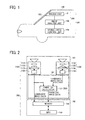
- FIG. 1 is a schematic diagram illustrating an in-vehicle control system 106 including a target recognition system 200 according to the present disclosure.
- the in-vehicle control system 106 controls the various devices in a vehicle 100 such as a car in accordance with recognition of targets using the captured image of the road in front of the vehicle 100 acquired by an imaging unit 101 installed in the vehicle 100.
- the in-vehicle control system 106 includes the imaging unit 101, an image analysis unit 102, and a vehicle drive control unit 104.
- the imaging unit 101 is provided as a capture device to capture an image of the area in front of the vehicle 100 in the direction of travel.
- the imaging unit 101 is provided near a rearview mirror near a windscreen 103 of the vehicle 100.
- the various data, such as, captured data acquired by the imaging unit 101 is input to the image analysis unit 102 as an image processor.
- the image analysis unit 102 analyzes the data transmitted from the imaging unit 101, calculates the position, the direction, and the distance of another vehicle in front of the vehicle 100, and detects the dividing line as the lane border.
- another vehicle leading vehicle, oncoming vehicle
- another vehicle is recognized as a recognition target on the road based on the luminance image.
- the vehicle drive control unit 104 performs driving support control to report the alert and control the steering and brakes of the vehicle 100, based on the detection of the recognition target such as another vehicle and pedestrian.
- the vehicle drive control unit 104 provides various functions having a brake-control-and-alert function that alerts the driver to take corrective action to avoid a collision or reduce the impact of the collision, and a driving speed adjustment function to maintain a safe minimum distance between vehicles by engaging a control device such as the brakes and the steering.
- FIG. 2 is a diagram illustrating a configuration of the imaging unit 101 and the image analysis unit 102.
- the imaging unit 101 is a stereo camera system that includes two cameras 110A and 110B, and the two cameras 110A and 110B have similar configuration. Respective cameras 110A and 110B include capturing lenses 111A and 111B, optical filters 112A and 112B, and image sensors 113A and 113B on which image capturing elements are two-dimensionally arranged.
- the imaging unit 101 outputs luminance data.
- the imaging unit 101 includes a process hardware unit 120 constituted by a field programmable-gate array (FPGA).
- the process hardware unit 120 includes a parallax calculator 121 to calculate parallaxes in the corresponding portions between the captured images, for acquiring the parallax data based on the luminance image data output from the respective imaging units 110A and 110B.
- the parallax for a certain area is calculated as position deviation in the certain image area in the comparison image correlated to the certain image area in the reference image.
- the distance from the stereo camera system to the same object corresponding to the certain image area in the captured image areas can be calculated based on the calculated parallax.
- the image analysis unit 102 includes a memory 130 and a micro processing unit (MPU) 140.
- the memory 130 stores luminance image data and parallax image data output from the imaging unit 101.
- the MPU 140 installs software that performs recognition processing to recognize targets and controls the parallax calculation.
- FIG. 3 is a schematic expanded view illustrating the optical filters 112A and 112B and the image sensors 113A and 113B viewed from a direction orthogonal to an optical transmission direction.
- Each of the image sensors 113A and 113B is constituted by, such as, charge coupled device (CCD) and Complementary Metal Oxide Semiconductor (CMOS), and the image capturing element (light-receiving element) is formed by photodiodes 113a.
- the photodiodes 113a are two dimensionally arranged for each of the imaging pixels in the image sensors 113A and 113B.
- a micro lens 113b is provided on the incoming side of the photodiodes 113a.
- FIG. 4 is a block diagram illustrating a configuration of the target recognition system 200 according to the present embodiment.
- the target recognition system 200 includes a stereo image input unit 201, a luminance image input unit 202, a parallax image calculator 203, a road area detector 204, a recognition weighting unit 205, a recognition target candidate detector 209, a parallax image calculator 206, a recognition target candidate dictionary 207, and a recognition result output unit 208.
- the luminance image input unit 202 receives the luminance image of right image or left image of the stereo image from the stereo image input unit 201.
- the input stereo image and the luminance image are stored in the memory 130 in the stereo camera system 101.
- the parallax image calculator 203 calculates the parallax (parallax image) of the captured targets that is the difference of the focusing position between the right image and the left image.
- the road area detector 204 serving as a recognition area detector, detects the road area from the captured image, using the parallax image calculated by the parallax image calculator 203.
- the recognition weighting unit 205 gives recognition weighting to the respective areas such as the road area or the rest area other than the road area such as sidewalk area, side strip area or background area.
- the recognition weighting unit 205 provides 1 recognition weighting to the road area and 0 recognition weighting to the rest area (others).
- the recognition target candidate detector 209 extracts a candidate set of the recognition target areas from the luminance image input from the luminance image input unit 202.
- the target recognition processor 206 performs recognition processing to recognize the recognition target from the candidate set of recognition target areas of a specific image area where the recognition weighting unit 205 weights the heavy probability of the image of the recognition targets being present from the candidate set of recognition target areas extracted by the recognition target detector 209.
- the recognition target candidate dictionary 207 is generated by the machine leaning method such as support vector machine (SVM) and generate image sample leaning data of the tare recognition in advance.
- the recognition target candidate dictionary 207 is generated for each of the respective recognition targets.
- the target recognition processor 206 performs the recognition processing.
- the target recognition processor 206 uses the recognition target candidate dictionary 207 to recognize the recognition targets.
- the target detection result output unit 208 outputs the recognition result of the recognition targets.
- FIG. 5 is a flow chart illustrating target recognition process executed by the target recognition system 200.
- the stereo image is input from stereo camera 101 to the stereo image input unit 101 (see FIG. 4 ).
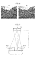
- FIG. 6 is one example of a stereo image. The same subject in the stereo image is positioned at different imaging positions in the right image and left image.
- the luminance image input unit 202 outputs luminance image of left image or right image at step S102.
- the input stereo image and the luminance image are saved in the memory 516 in the stereo camera system.
- the recognition target candidate detector 209 recognizes the candidate set of the recognition target areas where the recognition target is present, based on the luminance image stored in the memory in the stereo camera system.
- the parallax image calculator 203 calculates the parallax that is a difference between the image forming positions of the left image and the right image in the object of the stereo image, using the stereo image input from the stereo image input unit 201 at step S104. More specifically, the parallax image where the parallax is treated as the pixel value is calculated based on the same areas between the left image and the right image formed by the left image lens 111A and right image lens 111B using the block matching method.
- the block matching method is the method to divide the left image and the right image into multiple blocks and calculate the parallaxes based on the blocks where the degree of similarity between the left image and the right image is largest in the blocks and blocks between the left image and the right image is matched. For example, the image having 1280 x 960 pixels is divided into 5 x 5 pixel-size blocks. Then, the parallax is calculated using the respective blocks. The optimum values of the block sizes are set by adjusting through the experiment.
- the road area detector 204 ( FIG. 4 ) generates a horizontal line parallax histogram shown in FIG. 9B , using the parallax image acquired by the parallax image calculator 203.
- the horizontal line parallax histogram represents the histogram acquired by integrating the parallaxes contained in a single horizontal line of the parallax image shown in FIG. 9A . That is, a graph of FIG. 9B represents frequency distribution H ( ⁇ , y) at the parallaxes.
- a horizontal axis presents the parallax ⁇
- a vertical axis represents the parallax image.
- the values of the respective pixels of the horizontal line parallax histogram correspond to histogram values H ( ⁇ , y) of a single line at a height "y" of the parallax image.
- H ( ⁇ , y) histogram values of a single line at a height "y" of the parallax image.
- the horizontal line of the respective parallax images are constant on the horizontal line parallax histogram of FIG. 9B , and the parallaxes are gradually changed, and the histogram values H ( ⁇ , y) are arranged the starlight line on the horizontal line parallax histogram.
- the pixels arranged in the straight line on the horizontal line parallax histogram are detected, the pixels arranged in the straight line are found (mapping process) in the parallax image shown in FIG. 9A . That is, by correlating the pixels arranged in straight line on the horizontal line parallax histogram to the pixels on the road image in the parallax image, a border of a road area 301 can be identified.
- the road area detector 204 acquires the parallax distribution information of the parallax for each line on horizontal line parallax histogram. Then, the road area detector 204 converts the pixel distribution on the line parallax information into an approximate straight line data by approximating process using least-squares method and the Hough transform method.
- the acquired approximate straight line of FIG. 9B has a gradient whose parallax is smaller as the position is moved up in the image, in the horizontal line parallax histogram corresponding to the lower portion of the parallax image. That is, this graph of FIG. 9B indicates that the pixels (pixel in the parallax image) positioned on the approximate straight line or near the approximate straight line are present in the respective lines in the parallax image from almost same distance and is the highest occupancy and these pixels shows that the position of captured targets becomes continuously far from the vehicle 100 as the position of the graph is moved up.
- the pixels positioned on the approximated straight line or near the approximate straight line in the horizontal line parallax histogram represent the borders of the road area 301.
- the entire road area 302 can be detected.
- the road area may be detected by recognizing the side strip and dividing line from the luminance image and identifying the area where the continuous side strip and continuous dividing line are present.
- the stereo image input unit 201 captures the image ahead of the vehicle 100, in the contents of the parallax image like that shown in FIG. 9C , the road area is the largest portion in the lower area of the image, and as the image is upward, the parallax of the road area is smaller.
- the pixels constituting the road area have almost identical parallaxes. Accordingly, the pixels distributed on or near the approximated straight line on the horizontal line parallax histogram (distribution), identified by parallax distribution information of the respective horizontal line output from the parallax image calculator 203 correlate to the feature of the pixels constituting the road area. Therefore, it can be accurately assumed that the pixels distributed on or near the approximate straight line shown in FIG. 9B be the pixels constituting the road area.
- the road area detector 204 identifies the image showing a road area to be shown and detects the image area occupied by the identified image pixels as the road area. Then, when the road area is detected, the road area detector 204 also detects the rest image area, such as sidewalk and side strip, other than the vehicle road based on the vehicle road area at step S106.
- the recognition weighting unit 205 provides the recognition weighting to the road area and to the rest areas such as sidewalk, roadside, and background area based on the background ahead at step S107. That is, the recognition weighting unit 205 weights the probability of images of the recognition targets being present in each of the respective recognition areas detected by the road area detector 204.
- the recognition weighting unit 205 weights the probability of images of the recognition targets being present in each of the respective recognition areas detected by the road area detector 204.
- 1 recognition weighting is given to the road
- 0 recognition weighting is given to the rest image areas other than the road area.
- decimal recognition weighting can be given as illustrated in FIG. 11 .
- the parameters of the recognition can be adjusted depending on the magnitude of the recognition weighting.
- the target recognition processor 206 recognizes one or more recognition targets from the candidate set of recognition target areas, using the recognition target candidate dictionary 207, based on the recognition weighting given to the detected areas provided by the recognition weighting unit 205 at step S109. Then, the recognition result output unit 208 outputs the recognition processing result at step S110.
- rectangular or square blocks are set associated with target images in the captured image.
- the position and the size of the rectangular block in the captured image are determined by an upper left coordinate (Xs, Ys) and a lower right coordinate (Xe, Ye) of the rectangular.
- Xs, Ys upper left coordinate
- Xe, Ye lower right coordinate
- the captured images is scanned, and the target image is extracted so that the size of the rectangular block 1 almost matches the size of the target, and the rectangular blocks 1 is set for the extracted target images.
- the captured images is scanned, and then, the target image is extracted so that the size of the rectangular block 2 almost matches the size of the small target, and the rectangular block 2 is set for the extracted small target image. Accordingly, the rectangular blocks are set for the corresponding target images.
- the rectangular block is associated to the candidate set of recognition target areas.
- the target recognition processor 206 recognizes the recognition targets, using the recognition target candidate dictionary 207.
- the recognition target candidate dictionary 207 for recognizing the aimed recognition target is described below.
- the target recognition processor 206 calculates feature amount in a rectangular block of an evaluation target, based on a rectangular range 401 constituted by only white pixels and a rectangular range 402 constituted by only black pixels, represented by a shaded portion contained in a rectangular block 400 shown in FIG. 13 .
- the target recognition processor 206 calculates a difference between the pixels in the evaluation target rectangular block and the white pixels of the rectangular range 401 and between the pixels in the evaluation target rectangular block and the black pixel value of the rectangular block 402, and therefore, the difference in the sums are set as the feature amount h(x) in the rectangular block 400.
- the feature patterns A, B, C, and D shown in FIG. 13 almost fully cover features of ant targets.
- the rectangular range 401 and the rectangular range 402 are positioned adjacent from side to side, and both ranges are positioned upper left from the center of the rectangular block 400.
- the rectangular range 401 and the rectangular range 402 are positioned adjacent up and down, and both ranges are positioned upper left from the center of the rectangular block 400.
- the rectangular range 402 is sandwiched between two rectangular ranges 401, and both ranges are positioned upper from the center of the rectangular block 400.
- the rectangular range 401 and the rectangular range 402 are positioned diagonally, and both ranges are positioned left side from the center of the rectangular block 400.
- evaluation weight values f(x) in the candidate sets of recognition target areas are calculated based on an evaluation function like that shown in the formula 1.
- the weight evaluation value f(x) is calculated by integrating weight coefficients ⁇ t attached to each of the rectangular blocks.
- the feature amount h t (x) and the weight coefficient ⁇ t are obtained by collecting learning data for the image of the recognition target and by leveraging the learning data.
- the target recognition processor 206 includes multiple hierarchies 500-1 through 500-n (n; natural integer number).
- the target is evaluated using the weight evaluation values of the evaluation function represented by the formula (1).
- the evaluation is performed based on the formula (1).
- the huaraches vary from 500 -1 to 500-n, the number of used patterns is gradually increased. Accordingly, recognition speed can becomes faster.
- the rectangular block that is smaller than the threshold range set in advance, in the hierarchy 500-1 the aimed recognition target is not present in the rectangular block is determined. Then, without evaluating the rectangular block, the block is handled as a non-target block 500-1. Similar determination is performed for respective hierarchies 500-2 to 500-n (n: natural integer).
- the rectangular block, in which the recognition target in the final hierarchy 500-n is not the recognition target is not determined as the rectangular block in which the image of the aimed recognition target is present.
- the recognition weighting is additionally multiplied. Therefore, when 1 recognition weighting is given to the road area and 0 recognition weighting is given to the other area; that is, when the weight coefficient of the entire area other than the road area is 0, the recognition process is performed for the road area and is not performed for the areas other than the road area.
- the weight coefficient corresponding to decimal recognition weighting may be given, and the different weight coefficients may be set for the respective areas. In this case, even when the aimed recognition target is present in the respective area whose weight coefficient is set at a small value and the area whose weight coefficient is set at a larger value, the weight evaluation value in the area whose weight coefficient is small is small, that is not the image of the recognition target is determined.
- the recognition result of the recognition target in the area whose weight coefficient is small is bad, and the image of an object similar to the recognition target can be eliminated, thereby reducing the generation of false recognition.
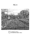
- FIG. 15 is image containing one example of the candidate set of recognition target areas set based on a detected recognition area in the captured image.
- the rectangular blocks surrounded by bold lines represent the candidate set of recognition target areas.
- the recognition weighting unit 605 weights most heavily the road area 603 in the recognition areas 601, 602, and 603 detected by the road area detector 204 to detect another vehicle. Since the candidate set of recognition target areas A, C, and D are positioned on a road area 601 where 1 recognition weighting is given, the recognition process is performed. Since the candidate set of recognition target areas B, D, and F are positioned on a non-recognition area 602 where 0 recognition weighting is given, the recognition process is not performed.
- the target recognition processor 206 does not perform the recognition process for the area where the recognition target is not present.
- the target recognition processor 206 can eliminate the candidate set of recognition target areas where the image of the object similar to the recognition target may be present, from the recognition targets. Accordingly, compared to the system that perform recognition processing for the entire candidate set of recognition target areas, falsely recognition can be reduced and the processing time can be shortened.
- the recognition weighting unit 205 weights the probability of images of the recognition targets being present in each of the respective recognition areas 601, 602, and 603 detected by the road area detector 204.
- the sidewalk and roadside 603 are detected based on the road area 601, treating the detected sidewalk and side strip 603 as a priority recognition area, and the recognition weighting unit 205 assigns 1 recognition weighting to the sidewalk and roadside 603. That is, the recognition weighting unit 605 weights most heavily the sidewalk and the roadside area 603 in the recognition areas 601, 602, and 603 detected by the road area detector 204.
- the system can alert the phenomena that the pedestrian runs into to vehicle lane to the driver. Accordingly, by setting the recognition weighting for recognition target depending on the intended use, recognition process can be performed with higher degree of accuracy corresponding to the intended use.
- the recognition weighting unit 205 weights the probability of images of the recognition targets being present in each of the respective recognition areas 604, 605, and 606 detected by the road area detector 204.
- the area close to the driver front side area is the area where the driver is likely to collide another vehicle and pedestrian, is treated as a priority recognition area.
- the range within predetermined distances from the driver is set as the priority recognition area. That is, the recognition weighting in the priority recognition area 604 positioned close to the driver is set heavier than a recognition area positioned far from the vehicle 100.
- the recognition weighting unit 205 weights most heavily a predetermined range of the road within a certain distance from the vehicle 100 in the recognition areas detected by the road area detector 204. Accordingly, the recognition target can be recognized with a higher degree of accuracy in the close, front road where the vehicle is likely to collide against the vehicle and the pedestrian.
- FIG. 17 is a block diagram illustrating one example of a hardware configuration of the stereo camera.
- a light reflected from the object is input to Complementary Metal Oxide Semiconductor (CMOS) 503 and 504 corresponding to the image sensors 112A and 112B (see FIG. 4 ) through the both imaging lenses 501 and 502 (112A and 112B) in the stereo camera.
- CMOS 503 and 504 convert the optical image formed on the captured image into electrical signals for outputting as analog image data.
- signal processor 114A and 114B include correlated double sampling (CDS) circuits 505 and 506, analog-digital (A/D) converters 507 and 508, and image processing circuits 509 and 510.
- CDS correlated double sampling
- Each of the process hardware unit 120 and the MPU 140 includes a central processing unit (CPU) 511, a synchronous dynamic random access memory (DRAM) 512, a compand (compress-expand) circuit 513, a read only memory (ROM) 516, random access memory (RAM) 517, and a timing signal generator circuit 518.
- Noise of the analog image data output from the CMOS 503 and 504 is removed by the CDS circuits 505 and 506, and the noise-removed image data is converted into digital signal, by the A/D converters 507 and 508, for outputting to the image processing circuits 509 and 510.
- the image processing circuits 509 and 510 performs various image processing, such as luminance-hue (YcrCb) conversion, white balance control processing, contrast correction processing, and edge emphasis processing.
- image processing shade of the image information is adjusted in the white balance processing, contrast of the image information is adjusted in the contrast correction processing, sharpness of the image information is adjusted in the edge emphasis processing, and color of the image information is adjusted in the color conversion processing.
- the image information in which the signal process and image process is executed is memorized in the memory card 514 via the compand circuit 513.
- the compand circuit 513 compresses the image information output from the image processing circuits 509 and 510 and expands the image information read from the memory card 514, to output the compressed and expanded information to the image processing circuit.
- the timings of the CMOS 503 and 504, the CDS circuits 505 and 506, and the A/D converters 507 and 508 are controlled by the CPU 511 via the timing signal generator 518 that generates the timing signal.
- the CPU 511 further controls the image processing circuits 509 and 510, the compand circuit 513, and the memory card 514.
- the CPU 511 performs various calculations depending on the target recognition program.
- the CPU 511 installs ROM 516 dedicated for storing the image processing program and RAM 517 that is a readably memory including a work area used for the various processes and various data storage area.
- the ROM 516 and RAM 517 are connected by a bus line 519.
- the stereo camera is constituted by module configuration including the process function to perform parallax calculation executed in the in-vehicle stereo camera system, to detect the candidate set of recognition target areas using the luminance image, perform the target recognition function to eliminate the false detection of the candidate set of recognition target areas
- the CPU 511 reads out the image processing program from the ROM 516, and the respective process are road on the main memory and the target recognition result is output.
- the method to recognize the recognition target is executed by the target recognition program to execute the recognition target.
- the target recognition program can engage a computer to execute a recognition area detecting process to detect multiple recognition areas from the captured image; a recognition weighting process to weight the probability of images of the recognition targets being present in each of the respective recognition areas detected by the recognition area detector; and a target recognition process to recognize the one or more recognition targets in a specified recognition area based on the recognition weighting given to the respective recognition areas.
- the present invention of the present disclosure can provide, in addition to the target recognition system and the target recognition method described above, a computer readable program for executing the method.
- the computer program to be executed by the target recognition system according to the present embodiment can be provided by being recorded in a computer-readable recording medium such as a CD-ROM, an FD, a CD-R, and a DVD as a file in an installable format or an executable format.
- the computer program to be executed by the target recognition system can be provided by being downloaded by a predetermined transmission device over a transmission medium, such as telephone line, dedicated network, Internet, and other communication systems.
- a transmission medium such as telephone line, dedicated network, Internet, and other communication systems.
- the communication medium is implemented by a carrier wave of a computer data signal containing the computer program.
- a communication method to transmit the computer program from the predetermined transmission device may contain a continuous transmission process to transmit the data constituting the computer program and an intermittent transmission process.
Landscapes
- Engineering & Computer Science (AREA)
- Physics & Mathematics (AREA)
- General Physics & Mathematics (AREA)
- Multimedia (AREA)
- Theoretical Computer Science (AREA)
- Image Analysis (AREA)
- Traffic Control Systems (AREA)
- Image Processing (AREA)
Abstract
Description
- The present invention relates to a target recognition system to recognize one or more recognition targets, a target recognition method executed by the target recognition system, target recognition program executed on the target recognition system, and a recording medium storing the target recognition program.
- At present, vehicle-mounted recognition systems that recognize obstacles based on a captured image of the area ahead of the vehicle are widely used for driver support systems such as adaptive cruise control (ACC), to reduce the burden on the driver.
- The driver support systems provide various functions, including a brake-control-and-alert function that alerts the driver to take corrective action to avoid a collision or reduce the impact of the collision, a driving speed adjustment function to maintain a safe minimum distance between vehicles, and a stray prevention function to prevent the vehicle from straying into another lane.
- In
JP-2008-146549-A - In order to implement the driver support system, it is necessary to recognize obstacles in the way of the vehicle accurately. However, in the above-described driver support system, the captured image may contain an image of an object similar to the recognition target. The system performs the same predetermined recognition processing to compare color and spatial frequency features of the image of the similar object with those of the recognition targets. As a result, the image of the object similar to the recognition target may be falsely recognized as the image of the recognition target, which makes it difficult to for the driver support system to function as intended.
- In one exemplary embodiment of the present disclosure, there is provided a target recognition system (200) to recognize one or more recognition targets (A, C, E), operatively connected to an imaging device (101) to capture an image of an area ahead of the target recognition system (200). The target recognition system (200) includes a recognition area detector (204), a recognition weighting unit (205), and a target recognition processor (206). The recognition area detector (204) detects multiple recognition areas (601, 602, 603) from the captured image. The recognition weighting unit (205) weights the probability of images of the recognition targets being present in each of the respective recognition areas (601, 602, 603) detected by the recognition area detector (204). The target recognition processor (206) recognizes the one or more recognition targets (A, C, E) in a specified recognition area (601) based on the recognition weighting given to the respective recognition areas (601, 602, 603).
- In another aspect of the present disclosure, there is a provided a target recognition method executed by the above-described target recognition system (200).
- A more complete appreciation of the disclosure and many of the attendant advantages thereof will be readily obtained as the same becomes better understood by reference to the following detailed description when considered in connection with the accompanying drawings, wherein:
-
FIG. 1 is a schematic diagram illustrating an in-vehicle control system including a target recognition system, according to the present disclosure; -
FIG. 2 is a diagram illustrating a configuration of an imaging unit and an image analysis unit shown inFIG. 1 ; -
FIG. 3 is a schematic expanded view illustrating optical filters shown inFIG. 2 viewed from a direction orthogonal to an optical transmission direction; -
FIG. 4 is a block diagram illustrating a configuration of a target recognition system; -
FIG. 5 is a flow chart illustrating target recognition process executed by the target recognition system; -
FIG. 6 is one example of the stereo image; -
FIG. 7 is a fundamental view illustrating a range finding in the stereo camera shown inFIG. 1 ; -
FIG. 8 is the captured image including multiple rectangular candidate set of recognition target areas; -
FIG. 9A is the image including multiple rectangular blocks; -
FIG. 9B is a graph illustrating a frequency value distribution at the parallaxes; -
FIG. 9C is the image showing a detected road area; -
FIG. 10 is a table illustrating one example of a setting table of recognition weighting; -
FIG. 11 is a table illustrating one example of a setting table of the recognition weighting; -
FIG. 12 illustrates the image including multiple rectangular blocks; -
FIGS. 13A through 13D illustrates examples of feature patterns in the rectangular blocks; -
FIG. 14 is a diagram illustrating a configuration of target recognition processor; -
FIG. 15 is one example of image containing a rectangular candidate set of recognition target areas, road area, and weight recognition area; -
FIG. 16 is another example of image containing a rectangular candidate set of recognition target areas, the road area, and the weight recognition area; and -
FIG. 17 is a block diagram illustrating a hardware configuration of the stereo camera system. - In describing preferred embodiments illustrated in the drawings, specific terminology is employed for the sake of clarity. However, the disclosure of this patent specification is not intended to be limited to the specific terminology so selected, and it is to be understood that each specific element includes all technical equivalents that have the same function, operate in a similar manner, and achieve a similar result. Referring now to the drawings, wherein like reference numerals designate identical or corresponding parts throughout the several views thereof, and particularly to
FIGS. 1 through 17 , a target recognition system according to illustrative embodiments of the present disclosure is described. - Initially, a vehicle-mounted control system includes a target recognition system as in-vehicle system. It is to be noted that the target recognition system according to the present disclosure is not limited to an in-vehicle control system, and thus, for example, the target recognition system may be used for an object detection device that detects the object based on captured images.
-
FIG. 1 is a schematic diagram illustrating an in-vehicle control system 106 including atarget recognition system 200 according to the present disclosure. The in-vehicle control system 106 controls the various devices in avehicle 100 such as a car in accordance with recognition of targets using the captured image of the road in front of thevehicle 100 acquired by animaging unit 101 installed in thevehicle 100. - In
FIG. 1 , the in-vehicle control system 106 includes theimaging unit 101, animage analysis unit 102, and a vehicledrive control unit 104. Theimaging unit 101 is provided as a capture device to capture an image of the area in front of thevehicle 100 in the direction of travel. For example, theimaging unit 101 is provided near a rearview mirror near awindscreen 103 of thevehicle 100. The various data, such as, captured data acquired by theimaging unit 101 is input to theimage analysis unit 102 as an image processor. Theimage analysis unit 102 analyzes the data transmitted from theimaging unit 101, calculates the position, the direction, and the distance of another vehicle in front of thevehicle 100, and detects the dividing line as the lane border. When another vehicle (leading vehicle, oncoming vehicle) is detected, another vehicle is recognized as a recognition target on the road based on the luminance image. - In addition, the calculation result of the
image analysis unit 102 is transmitted to the vehicledrive control unit 104. The vehicledrive control unit 104 performs driving support control to report the alert and control the steering and brakes of thevehicle 100, based on the detection of the recognition target such as another vehicle and pedestrian. The vehicledrive control unit 104 provides various functions having a brake-control-and-alert function that alerts the driver to take corrective action to avoid a collision or reduce the impact of the collision, and a driving speed adjustment function to maintain a safe minimum distance between vehicles by engaging a control device such as the brakes and the steering. -
FIG. 2 is a diagram illustrating a configuration of theimaging unit 101 and theimage analysis unit 102. Theimaging unit 101 is a stereo camera system that includes twocameras cameras Respective cameras lenses optical filters 112A and 112B, andimage sensors imaging unit 101 outputs luminance data. - In addition, the
imaging unit 101 includes aprocess hardware unit 120 constituted by a field programmable-gate array (FPGA). Theprocess hardware unit 120 includes aparallax calculator 121 to calculate parallaxes in the corresponding portions between the captured images, for acquiring the parallax data based on the luminance image data output from therespective imaging units imaging devices imaging devices - The
image analysis unit 102 includes amemory 130 and a micro processing unit (MPU) 140. Thememory 130 stores luminance image data and parallax image data output from theimaging unit 101. TheMPU 140 installs software that performs recognition processing to recognize targets and controls the parallax calculation. -
FIG. 3 is a schematic expanded view illustrating theoptical filters 112A and 112B and theimage sensors image sensors photodiodes 113a. Thephotodiodes 113a are two dimensionally arranged for each of the imaging pixels in theimage sensors micro lens 113b is provided on the incoming side of thephotodiodes 113a. By connecting theimage sensors sensor substrates - Next, the target recognition process executed by the
imaging unit 101 and the image analysis unit 102(target recognition system 200) is described below with reference toFIG. 4. FIG. 4 is a block diagram illustrating a configuration of thetarget recognition system 200 according to the present embodiment. InFIG. 4 , thetarget recognition system 200 includes a stereoimage input unit 201, a luminanceimage input unit 202, aparallax image calculator 203, aroad area detector 204, arecognition weighting unit 205, a recognitiontarget candidate detector 209, aparallax image calculator 206, a recognitiontarget candidate dictionary 207, and a recognitionresult output unit 208. - The luminance
image input unit 202 receives the luminance image of right image or left image of the stereo image from the stereoimage input unit 201. The input stereo image and the luminance image are stored in thememory 130 in thestereo camera system 101. Theparallax image calculator 203 calculates the parallax (parallax image) of the captured targets that is the difference of the focusing position between the right image and the left image. Theroad area detector 204, serving as a recognition area detector, detects the road area from the captured image, using the parallax image calculated by theparallax image calculator 203. Therecognition weighting unit 205 gives recognition weighting to the respective areas such as the road area or the rest area other than the road area such as sidewalk area, side strip area or background area. For example, when the recognition target is another vehicle, therecognition weighting unit 205 provides 1 recognition weighting to the road area and 0 recognition weighting to the rest area (others). The recognitiontarget candidate detector 209 extracts a candidate set of the recognition target areas from the luminance image input from the luminanceimage input unit 202. - Then, the
target recognition processor 206 performs recognition processing to recognize the recognition target from the candidate set of recognition target areas of a specific image area where therecognition weighting unit 205 weights the heavy probability of the image of the recognition targets being present from the candidate set of recognition target areas extracted by therecognition target detector 209. The recognitiontarget candidate dictionary 207 is generated by the machine leaning method such as support vector machine (SVM) and generate image sample leaning data of the tare recognition in advance. The recognitiontarget candidate dictionary 207 is generated for each of the respective recognition targets. Thetarget recognition processor 206 performs the recognition processing. Thetarget recognition processor 206 uses the recognitiontarget candidate dictionary 207 to recognize the recognition targets. The target detectionresult output unit 208 outputs the recognition result of the recognition targets. - Next, operation flow of the
target recognition system 200 is described below with reference toFIG. 5. FIG. 5 is a flow chart illustrating target recognition process executed by thetarget recognition system 200. At step S101, the stereo image is input fromstereo camera 101 to the stereo image input unit 101 (seeFIG. 4 ).FIG. 6 is one example of a stereo image. The same subject in the stereo image is positioned at different imaging positions in the right image and left image. - Then, the luminance
image input unit 202 outputs luminance image of left image or right image at step S102. The input stereo image and the luminance image are saved in the memory 516 in the stereo camera system. - At S103, the recognition
target candidate detector 209 recognizes the candidate set of the recognition target areas where the recognition target is present, based on the luminance image stored in the memory in the stereo camera system. - Along with these processes, the
parallax image calculator 203 calculates the parallax that is a difference between the image forming positions of the left image and the right image in the object of the stereo image, using the stereo image input from the stereoimage input unit 201 at step S104. More specifically, the parallax image where the parallax is treated as the pixel value is calculated based on the same areas between the left image and the right image formed by theleft image lens 111A andright image lens 111B using the block matching method. - The block matching method is the method to divide the left image and the right image into multiple blocks and calculate the parallaxes based on the blocks where the degree of similarity between the left image and the right image is largest in the blocks and blocks between the left image and the right image is matched. For example, the image having 1280 x 960 pixels is divided into 5 x 5 pixel-size blocks. Then, the parallax is calculated using the respective blocks. The optimum values of the block sizes are set by adjusting through the experiment.
- In one example illustrated in
FIG. 7 , Δ1 and Δ2 represent distances from image center positions to actual image positions in the right image and the left image showing a point O in the capturing target. Accordingly, the parallax Δ can be obtained by adding the distance Δ1 and the distance Δ2 (Δ = Δ1 + Δ2). Accordingly, the parallax image has parallaxes in the corresponding pixel positions. - At step S105, the road area detector 204 (
FIG. 4 ) generates a horizontal line parallax histogram shown inFIG. 9B , using the parallax image acquired by theparallax image calculator 203. The horizontal line parallax histogram represents the histogram acquired by integrating the parallaxes contained in a single horizontal line of the parallax image shown inFIG. 9A . That is, a graph ofFIG. 9B represents frequency distribution H (Δ, y) at the parallaxes. InFIG. 9A , a horizontal axis presents the parallax Δ, and a vertical axis represents the parallax image. The values of the respective pixels of the horizontal line parallax histogram correspond to histogram values H (Δ, y) of a single line at a height "y" of the parallax image. When the road area is present, the parallax histogram H on the signal horizontal line at a height y from the road has a great value because the entire parallax pixels converge to a same parallax Δy. - In the road area, the horizontal line of the respective parallax images are constant on the horizontal line parallax histogram of
FIG. 9B , and the parallaxes are gradually changed, and the histogram values H (Δ, y) are arranged the starlight line on the horizontal line parallax histogram. After the pixels arranged in the straight line on the horizontal line parallax histogram are detected, the pixels arranged in the straight line are found (mapping process) in the parallax image shown inFIG. 9A . That is, by correlating the pixels arranged in straight line on the horizontal line parallax histogram to the pixels on the road image in the parallax image, a border of aroad area 301 can be identified. - After the points on the
road area 301 are recognized, by performing interpolate process among the respective points, anentire road area 302 like that shown inFIG. 9C can be detected. More specifically, theroad area detector 204 acquires the parallax distribution information of the parallax for each line on horizontal line parallax histogram. Then, theroad area detector 204 converts the pixel distribution on the line parallax information into an approximate straight line data by approximating process using least-squares method and the Hough transform method. - The acquired approximate straight line of
FIG. 9B has a gradient whose parallax is smaller as the position is moved up in the image, in the horizontal line parallax histogram corresponding to the lower portion of the parallax image. That is, this graph ofFIG. 9B indicates that the pixels (pixel in the parallax image) positioned on the approximate straight line or near the approximate straight line are present in the respective lines in the parallax image from almost same distance and is the highest occupancy and these pixels shows that the position of captured targets becomes continuously far from thevehicle 100 as the position of the graph is moved up. - That is, the pixels positioned on the approximated straight line or near the approximate straight line in the horizontal line parallax histogram represent the borders of the
road area 301. As a result, by identifying the pixels positioned on the approximated straight line or near the approximate straight line on the horizontal line parallax histogram, theentire road area 302 can be detected. - It is to be noted that, although detecting the road area can be accurately performed, using above-described method, alternatively, the road area may be detected by recognizing the side strip and dividing line from the luminance image and identifying the area where the continuous side strip and continuous dividing line are present.
- Since the stereo
image input unit 201 captures the image ahead of thevehicle 100, in the contents of the parallax image like that shown inFIG. 9C , the road area is the largest portion in the lower area of the image, and as the image is upward, the parallax of the road area is smaller. In addition, in the same horizontal line, the pixels constituting the road area have almost identical parallaxes. Accordingly, the pixels distributed on or near the approximated straight line on the horizontal line parallax histogram (distribution), identified by parallax distribution information of the respective horizontal line output from theparallax image calculator 203 correlate to the feature of the pixels constituting the road area. Therefore, it can be accurately assumed that the pixels distributed on or near the approximate straight line shown inFIG. 9B be the pixels constituting the road area. - As described above, the
road area detector 204 identifies the image showing a road area to be shown and detects the image area occupied by the identified image pixels as the road area. Then, when the road area is detected, theroad area detector 204 also detects the rest image area, such as sidewalk and side strip, other than the vehicle road based on the vehicle road area at step S106. - The
recognition weighting unit 205 provides the recognition weighting to the road area and to the rest areas such as sidewalk, roadside, and background area based on the background ahead at step S107. That is, therecognition weighting unit 205 weights the probability of images of the recognition targets being present in each of the respective recognition areas detected by theroad area detector 204. In the present embodiment, as illustrated inFIG. 10 , when the images of the recognition targets, such as vehicle and the pedestrian on the road area are recognized, 1 recognition weighting is given to the road, and 0 recognition weighting is given to the rest image areas other than the road area. Although 0 and 1 recognition weighting are given as described above; alternatively, decimal recognition weighting can be given as illustrated inFIG. 11 . The parameters of the recognition can be adjusted depending on the magnitude of the recognition weighting. - When the recognition weighting is not 0 (Yes at step S108), the
target recognition processor 206 recognizes one or more recognition targets from the candidate set of recognition target areas, using the recognitiontarget candidate dictionary 207, based on the recognition weighting given to the detected areas provided by therecognition weighting unit 205 at step S109. Then, the recognitionresult output unit 208 outputs the recognition processing result at step S110. - Herein, the detail recognition process to recognize the recognition target according to the present disclosure is described below. Initially, in order to recognize the recognition target, as illustrated in
FIG. 12 , rectangular or square blocks are set associated with target images in the captured image. The position and the size of the rectangular block in the captured image are determined by an upper left coordinate (Xs, Ys) and a lower right coordinate (Xe, Ye) of the rectangular. Then, using a largerectangular block 1, the captured images is scanned, and the target image is extracted so that the size of therectangular block 1 almost matches the size of the target, and therectangular blocks 1 is set for the extracted target images. - After setting the
rectangular block 1, using a smallrectangular block 2, the captured images is scanned, and then, the target image is extracted so that the size of therectangular block 2 almost matches the size of the small target, and therectangular block 2 is set for the extracted small target image. Accordingly, the rectangular blocks are set for the corresponding target images. The rectangular block is associated to the candidate set of recognition target areas. - Then, the
target recognition processor 206 recognizes the recognition targets, using the recognitiontarget candidate dictionary 207. Herein, the recognitiontarget candidate dictionary 207 for recognizing the aimed recognition target is described below. - As illustrated in
FIG. 13 , thetarget recognition processor 206 calculates feature amount in a rectangular block of an evaluation target, based on arectangular range 401 constituted by only white pixels and arectangular range 402 constituted by only black pixels, represented by a shaded portion contained in arectangular block 400 shown inFIG. 13 . Thetarget recognition processor 206 calculates a difference between the pixels in the evaluation target rectangular block and the white pixels of therectangular range 401 and between the pixels in the evaluation target rectangular block and the black pixel value of therectangular block 402, and therefore, the difference in the sums are set as the feature amount h(x) in therectangular block 400. - The feature patterns A, B, C, and D shown in
FIG. 13 almost fully cover features of ant targets. In the feature pattern A, therectangular range 401 and therectangular range 402 are positioned adjacent from side to side, and both ranges are positioned upper left from the center of therectangular block 400. In the feature pattern B, therectangular range 401 and therectangular range 402 are positioned adjacent up and down, and both ranges are positioned upper left from the center of therectangular block 400. In the feature pattern C, therectangular range 402 is sandwiched between tworectangular ranges 401, and both ranges are positioned upper from the center of therectangular block 400. In the feature pattern D, therectangular range 401 and therectangular range 402 are positioned diagonally, and both ranges are positioned left side from the center of therectangular block 400. - Then, using the evaluation function like that shown in the
formula 1, evaluation weight values f(x) in the candidate sets of recognition target areas are calculated based on an evaluation function like that shown in theformula 1. By calculating the feature amount ht(x) in the entire pixels T in the rectangular blocks t (1 to T) (T; the number of patterns used for evaluation), the weight evaluation value f(x) is calculated by integrating weight coefficients αt attached to each of the rectangular blocks. - Herein, the feature amount ht(x) and the weight coefficient αt are obtained by collecting learning data for the image of the recognition target and by leveraging the learning data. By calculating the weight evaluation values for the above-described feature patterns A through D, the recognition
target candidate dictionary 207 saves pairs of the feature pattern and weight coefficient αt based on the calculated weight evaluation values
- Herein, the
target recognition processor 206 includes multiple hierarchies 500-1 through 500-n (n; natural integer number). In the respective hierarchies 500-1 through 500-n, the target is evaluated using the weight evaluation values of the evaluation function represented by the formula (1). - In the respective hierarchies 500-1 through 500-n, using a unique feature pattern for each of recognition targets or multiple feature patterns for each of recognition targets and weight coefficients associated to the feature pattern(s), the evaluation is performed based on the formula (1). In general, the huaraches vary from 500 -1 to 500-n, the number of used patterns is gradually increased. Accordingly, recognition speed can becomes faster. For example, when the rectangular block that is smaller than the threshold range set in advance, in the hierarchy 500-1, the aimed recognition target is not present in the rectangular block is determined. Then, without evaluating the rectangular block, the block is handled as a non-target block 500-1. Similar determination is performed for respective hierarchies 500-2 to 500-n (n: natural integer). The rectangular block, in which the recognition target in the final hierarchy 500-n is not the recognition target, is not determined as the rectangular block in which the image of the aimed recognition target is present.
- When the feature amount is calculated, the recognition weighting is additionally multiplied. Therefore, when 1 recognition weighting is given to the road area and 0 recognition weighting is given to the other area; that is, when the weight coefficient of the entire area other than the road area is 0, the recognition process is performed for the road area and is not performed for the areas other than the road area. Alternatively, the weight coefficient corresponding to decimal recognition weighting may be given, and the different weight coefficients may be set for the respective areas. In this case, even when the aimed recognition target is present in the respective area whose weight coefficient is set at a small value and the area whose weight coefficient is set at a larger value, the weight evaluation value in the area whose weight coefficient is small is small, that is not the image of the recognition target is determined.
- Accordingly, the recognition result of the recognition target in the area whose weight coefficient is small is bad, and the image of an object similar to the recognition target can be eliminated, thereby reducing the generation of false recognition.
-
FIG. 15 is image containing one example of the candidate set of recognition target areas set based on a detected recognition area in the captured image. InFIG. 15 , the rectangular blocks surrounded by bold lines represent the candidate set of recognition target areas. In this embodiment, therecognition weighting unit 605 weights most heavily theroad area 603 in therecognition areas road area detector 204 to detect another vehicle. Since the candidate set of recognition target areas A, C, and D are positioned on aroad area 601 where 1 recognition weighting is given, the recognition process is performed. Since the candidate set of recognition target areas B, D, and F are positioned on anon-recognition area 602 where 0 recognition weighting is given, the recognition process is not performed. - As described above, the
target recognition processor 206 does not perform the recognition process for the area where the recognition target is not present. Thetarget recognition processor 206 can eliminate the candidate set of recognition target areas where the image of the object similar to the recognition target may be present, from the recognition targets. Accordingly, compared to the system that perform recognition processing for the entire candidate set of recognition target areas, falsely recognition can be reduced and the processing time can be shortened. - Next, another recognition process in the
target recognition system 1 according to a first variation is described below. As illustrated inFIG. 15 , when theroad area 601 is detected, therecognition weighting unit 205 weights the probability of images of the recognition targets being present in each of therespective recognition areas road area detector 204. For example, for the purpose of recognizing the image of the pedestrian, the sidewalk androadside 603 are detected based on theroad area 601, treating the detected sidewalk andside strip 603 as a priority recognition area, and therecognition weighting unit 205 assigns 1 recognition weighting to the sidewalk androadside 603. That is, therecognition weighting unit 605 weights most heavily the sidewalk and theroadside area 603 in therecognition areas road area detector 204. - With this setting, the system can alert the phenomena that the pedestrian runs into to vehicle lane to the driver. Accordingly, by setting the recognition weighting for recognition target depending on the intended use, recognition process can be performed with higher degree of accuracy corresponding to the intended use.
- Next, yet another recognition process in the
target recognition system 200 according to a second variation is described below. As illustrated inFIG. 16 , when theroad area 601 is detected, therecognition weighting unit 205 weights the probability of images of the recognition targets being present in each of therespective recognition areas road area detector 204. For example, the area close to the driver front side area is the area where the driver is likely to collide another vehicle and pedestrian, is treated as a priority recognition area. In order to set the priority, as illustrated inFIG. 16 , the range within predetermined distances from the driver is set as the priority recognition area. That is, the recognition weighting in thepriority recognition area 604 positioned close to the driver is set heavier than a recognition area positioned far from thevehicle 100. That is, therecognition weighting unit 205 weights most heavily a predetermined range of the road within a certain distance from thevehicle 100 in the recognition areas detected by theroad area detector 204. Accordingly, the recognition target can be recognized with a higher degree of accuracy in the close, front road where the vehicle is likely to collide against the vehicle and the pedestrian. - A hardware configuration of the in-vehicle stereo camera system used for recognizing the recognition target is described below with reference to
FIG. 17. FIG. 17 is a block diagram illustrating one example of a hardware configuration of the stereo camera. InFIG. 17 , a light reflected from the object is input to Complementary Metal Oxide Semiconductor (CMOS) 503 and 504 corresponding to theimage sensors 112A and 112B (seeFIG. 4 ) through the bothimaging lenses 501 and 502 (112A and 112B) in the stereo camera. The CMOS 503 and 504 convert the optical image formed on the captured image into electrical signals for outputting as analog image data. Then, signalprocessor process hardware unit 120 and theMPU 140 includes a central processing unit (CPU) 511, a synchronous dynamic random access memory (DRAM) 512, a compand (compress-expand) circuit 513, a read only memory (ROM) 516, random access memory (RAM) 517, and a timing signal generator circuit 518. Noise of the analog image data output from the CMOS 503 and 504 is removed by the CDS circuits 505 and 506, and the noise-removed image data is converted into digital signal, by the A/D converters 507 and 508, for outputting to the image processing circuits 509 and 510. - Using the SDRAM 512 that temporarily saves the image data, the image processing circuits 509 and 510 performs various image processing, such as luminance-hue (YcrCb) conversion, white balance control processing, contrast correction processing, and edge emphasis processing. In the processes of image processing, shade of the image information is adjusted in the white balance processing, contrast of the image information is adjusted in the contrast correction processing, sharpness of the image information is adjusted in the edge emphasis processing, and color of the image information is adjusted in the color conversion processing.
- In addition, the image information in which the signal process and image process is executed is memorized in the memory card 514 via the compand circuit 513. The compand circuit 513 compresses the image information output from the image processing circuits 509 and 510 and expands the image information read from the memory card 514, to output the compressed and expanded information to the image processing circuit. The timings of the CMOS 503 and 504, the CDS circuits 505 and 506, and the A/D converters 507 and 508 are controlled by the CPU 511 via the timing signal generator 518 that generates the timing signal. Furthermore, the CPU 511 further controls the image processing circuits 509 and 510, the compand circuit 513, and the memory card 514.
- In the stereo camera system, the CPU 511 performs various calculations depending on the target recognition program. The CPU 511 installs ROM 516 dedicated for storing the image processing program and RAM 517 that is a readably memory including a work area used for the various processes and various data storage area. The ROM 516 and RAM 517 are connected by a bus line 519. With this configuration, the stereo camera is constituted by module configuration including the process function to perform parallax calculation executed in the in-vehicle stereo camera system, to detect the candidate set of recognition target areas using the luminance image, perform the target recognition function to eliminate the false detection of the candidate set of recognition target areas As the actual hardware configuration, the CPU 511 reads out the image processing program from the ROM 516, and the respective process are road on the main memory and the target recognition result is output.
- In addition, the method to recognize the recognition target is executed by the target recognition program to execute the recognition target. The target recognition program can engage a computer to execute a recognition area detecting process to detect multiple recognition areas from the captured image; a recognition weighting process to weight the probability of images of the recognition targets being present in each of the respective recognition areas detected by the recognition area detector; and a target recognition process to recognize the one or more recognition targets in a specified recognition area based on the recognition weighting given to the respective recognition areas. With this configuration, the generation of false recognition can be prevented as describe above.
- Herein, the present invention of the present disclosure can provide, in addition to the target recognition system and the target recognition method described above, a computer readable program for executing the method. The computer program to be executed by the target recognition system according to the present embodiment can be provided by being recorded in a computer-readable recording medium such as a CD-ROM, an FD, a CD-R, and a DVD as a file in an installable format or an executable format.
- Alternatively, the computer program to be executed by the target recognition system according to the present embodiment can be provided by being downloaded by a predetermined transmission device over a transmission medium, such as telephone line, dedicated network, Internet, and other communication systems. Herein, while transmitting the program, at least a part of computer program should be transmitted through the transmission medium. That is, not all of data constituting the computer program should be present in the communication medium (signal) at one time. The communication medium (signal) is implemented by a carrier wave of a computer data signal containing the computer program. A communication method to transmit the computer program from the predetermined transmission device may contain a continuous transmission process to transmit the data constituting the computer program and an intermittent transmission process.
Claims (12)
- A target recognition system (200) to recognize one or more recognition targets (A, C, E), operatively connected to an imaging device (101) to capture an image of an area ahead of the target recognition system (200), comprising:a recognition area detector (204) to detect multiple recognition areas (601, 602, 603) from the captured image;a recognition weighting unit (205) to weight the probability of images of the recognition targets (A, B, C, D, E, F) being present in each of the respective recognition areas (601, 602, 603) detected by the recognition area detector (204); anda target recognition processor (206) to recognize the one or more recognition targets (A, C, E) in a specified recognition area (601) based on the recognition weighting given to the respective recognition areas (601, 602, 603).
- The target recognition system (200) according to claim 1, wherein the imaging device has a stereo imaging device (101) to capture a stereo image including two images,
the recognition system (200) further comprising a parallax calculator (204) to calculate parallax of the captured image from the two images in the stereo image,
wherein the recognition area detector (206) detects multiple recognition areas from a luminance image of one of the images in the stereo image or a parallax image having pixel values corresponding to the parallax calculated by the parallax calculator. - The target recognition system (200) according to claim 2, wherein the recognition area detector (204) classifies the multiple recognition areas (601, 602, 603), using the parallax of the captured image calculated by the parallax calculator (203), based on frequency distribution at respective heights in the captured image.
- The target recognition system (200) according to any one of claims 1 to 3, wherein the recognition weighting unit (205) weights most heavily a road area (601) in the recognition areas (601, 602, 603) detected by the recognition area detector (204).
- The target recognition system (200) according to any one of claims 1 to 3, wherein the recognition weighting unit (205) weights most heavily a sidewalk and a roadside area (603) in the recognition areas (601, 602, 603) detected by the recognition area detector (204).
- The target recognition system (200) according to any one of claims 1 to 3, wherein the recognition weighting unit (205) weights most heavily a predetermined range of the road (604) within a certain distance from the target recognition system (200) in the recognition areas (604, 605, 606) detected by the recognition area detector (204).
- The target recognition system (200) according to any one of claims 1 to 6, further comprising:a target candidate detector (209) to detect a candidate set of recognition target areas (A, B, C, D, E, F) based on a luminance of the captured image,wherein the target recognition processor (206) recognizes the one or more recognition targets (A, C, E) from the candidate set of recognition target areas (A, B, C, D, E, F) detected by the target candidate detector (209) in the specified recognition area (601) detected by the recognition area detector based on the weighting of the recognition areas (601, 602, 603).
- A target recognition method executed by a target recognition system (200) to recognize one or more recognition targets (A, C, E), operatively connected to an imaging device (101) to capture a stereo image of an area ahead of the target recognition system (200),
the method comprising the steps of:detecting multiple recognition areas (601, 602, 603) from the captured image;weighting the probability of images of the recognition targets being present in each of the respective recognition areas (601, 602, 603); andrecognizing the one or more recognition targets (A, C, E) in a specified recognition area based on the recognition weighting given to the respective recognition areas (601, 602, 603). - The target recognition method according to claim 8, further comprising:capturing a stereo image including two images,calculating parallax of the captured image from the two images in the stereo image,wherein the multiple recognition areas (A, C, E) are detected from a luminance image of one of the images in the stereo image or a parallax image having pixel values corresponding to the parallax.
- The target recognition method according to claim 8 or 9, further comprising:detecting a candidate set of recognition target areas (A, B, C, D, E, F) based on a luminance of the captured image,wherein the one or more recognition targets (A, C, E) are recognized from the candidate set of recognition target areas (A, B, C, D, E, F) in the specified recognition area (601) recognition areas based on the weighting of the recognition areas (601, 602, 603).
- A target recognition program comprising computer program code means that, when executed on the target recognition system (200), instructs the target recognition system (200) to perform the target recognition method of any one of claims 8 through 10.
- A recording medium storing the computer program code means of claim 11.
Applications Claiming Priority (2)
| Application Number | Priority Date | Filing Date | Title |
|---|---|---|---|
| JP2012126412 | 2012-06-01 | ||
| JP2013077228 | 2013-04-02 |
Publications (2)
| Publication Number | Publication Date |
|---|---|
| EP2669845A2 true EP2669845A2 (en) | 2013-12-04 |
| EP2669845A3 EP2669845A3 (en) | 2014-11-19 |
Family
ID=48578798
Family Applications (1)
| Application Number | Title | Priority Date | Filing Date |
|---|---|---|---|
| EP13169614.8A Ceased EP2669845A3 (en) | 2012-06-01 | 2013-05-29 | Target recognition system, target recognition method executed by the target recognition system, target recognition program executed on the target recognition system, and recording medium storing the target recognition program |
Country Status (4)
| Country | Link |
|---|---|
| US (1) | US8965052B2 (en) |
| EP (1) | EP2669845A3 (en) |
| JP (1) | JP6156733B2 (en) |
| CN (1) | CN103455812B (en) |
Cited By (1)
| Publication number | Priority date | Publication date | Assignee | Title |
|---|---|---|---|---|
| EP2889641A1 (en) * | 2013-12-27 | 2015-07-01 | Ricoh Company, Ltd. | Image processing apparatus, image processing method, program and image processing system |
Families Citing this family (40)
| Publication number | Priority date | Publication date | Assignee | Title |
|---|---|---|---|---|
| WO2013056241A2 (en) | 2011-10-14 | 2013-04-18 | Pacific Biosciences Of California, Inc. | Real-time redox sequencing |
| JP2014115978A (en) | 2012-11-19 | 2014-06-26 | Ricoh Co Ltd | Mobile object recognition device, notification apparatus using the device, mobile object recognition program for use in the mobile object recognition device, and mobile object with the mobile object recognition device |
| JP6344638B2 (en) | 2013-03-06 | 2018-06-20 | 株式会社リコー | Object detection apparatus, mobile device control system, and object detection program |
| WO2014206406A1 (en) * | 2013-06-26 | 2014-12-31 | Conti Temic Microelectronic Gmbh | Mirror-replacement device and vehicle |
| DE102013214368A1 (en) | 2013-07-23 | 2015-01-29 | Application Solutions (Electronics and Vision) Ltd. | Method and device for reproducing a lateral and / or rear surrounding area of a vehicle |
| JP6151150B2 (en) * | 2013-10-07 | 2017-06-21 | 日立オートモティブシステムズ株式会社 | Object detection device and vehicle using the same |
| WO2016027289A1 (en) * | 2014-08-21 | 2016-02-25 | 三菱電機株式会社 | Drive assist device, drive assist method, and program |
| KR102310286B1 (en) * | 2014-11-07 | 2021-10-07 | 현대모비스 주식회사 | Apparatus and method for specific object detection |
| JP6459443B2 (en) | 2014-11-28 | 2019-01-30 | 株式会社リコー | Detection device, detection system, detection method and program |
| JP2016140030A (en) | 2015-01-29 | 2016-08-04 | 株式会社リコー | Image processing apparatus, imaging apparatus, and image processing program |
| JP6156400B2 (en) * | 2015-02-09 | 2017-07-05 | トヨタ自動車株式会社 | Traveling road surface detection device and traveling road surface detection method |
| US9916508B2 (en) | 2015-03-12 | 2018-03-13 | Toyota Jidosha Kabushiki Kaisha | Detecting roadway objects in real-time images |
| JP6233345B2 (en) * | 2015-04-17 | 2017-11-22 | トヨタ自動車株式会社 | Road surface gradient detector |
| JP2016206774A (en) * | 2015-04-17 | 2016-12-08 | トヨタ自動車株式会社 | Three-dimensional object detection apparatus and three-dimensional object detection method |
| JP6350374B2 (en) * | 2015-04-17 | 2018-07-04 | トヨタ自動車株式会社 | Road surface detection device |
| CN107615334B (en) * | 2015-06-10 | 2020-11-06 | 株式会社日立制作所 | Object recognition device and object recognition system |
| JP6618767B2 (en) * | 2015-10-27 | 2019-12-11 | 株式会社デンソーテン | Image processing apparatus and image processing method |
| JP6728634B2 (en) | 2015-11-04 | 2020-07-22 | 株式会社リコー | Detecting device, detecting method and program |
| DE112015007054B4 (en) | 2015-11-20 | 2019-11-28 | Mitsubishi Electric Corp. | TRAVEL SUPPORT DEVICE, TRAVEL SUPPORT SYSTEM, TRAVEL SUPPORT PROCEDURE AND TRAVEL SUPPORT PROGRAM |
| CN105740802A (en) * | 2016-01-28 | 2016-07-06 | 北京中科慧眼科技有限公司 | Disparity map-based obstacle detection method and device as well as automobile driving assistance system |
| US10239539B2 (en) * | 2016-01-29 | 2019-03-26 | Nissan Motor Co., Ltd. | Vehicle travel control method and vehicle travel control device |
| JP6601679B2 (en) * | 2016-03-01 | 2019-11-06 | パナソニックIpマネジメント株式会社 | Determination device, determination method, and determination program |
| JP6671033B2 (en) * | 2016-03-29 | 2020-03-25 | パナソニックIpマネジメント株式会社 | Vehicle status determination device, vehicle status determination method, and vehicle status determination program |
| US9805276B2 (en) * | 2016-03-31 | 2017-10-31 | Toyota Jidosha Kabushiki Kaisha | Generating real-time driver familiarity index for fine-grained dynamic road scenes |
| US10916135B2 (en) | 2018-01-13 | 2021-02-09 | Toyota Jidosha Kabushiki Kaisha | Similarity learning and association between observations of multiple connected vehicles |
| US10586118B2 (en) * | 2018-01-13 | 2020-03-10 | Toyota Jidosha Kabushiki Kaisha | Localizing traffic situation using multi-vehicle collaboration |
| US10963706B2 (en) | 2018-01-13 | 2021-03-30 | Toyota Jidosha Kabushiki Kaisha | Distributable representation learning for associating observations from multiple vehicles |
| US11281926B2 (en) * | 2018-06-04 | 2022-03-22 | Denso Corporation | Feature extraction method and apparatus |
| US10495476B1 (en) * | 2018-09-27 | 2019-12-03 | Phiar Technologies, Inc. | Augmented reality navigation systems and methods |
| US11448518B2 (en) * | 2018-09-27 | 2022-09-20 | Phiar Technologies, Inc. | Augmented reality navigational overlay |
| CN109166261B (en) * | 2018-10-11 | 2022-06-07 | 平安科技(深圳)有限公司 | Image processing method, device and equipment based on image recognition and storage medium |
| CN110597266A (en) * | 2019-09-26 | 2019-12-20 | 青岛蚂蚁机器人有限责任公司 | Robot path dynamic planning method based on two-dimensional code |
| JP7395913B2 (en) * | 2019-09-30 | 2023-12-12 | 株式会社アイシン | object detection device |
| JP7408358B2 (en) * | 2019-11-18 | 2024-01-05 | キヤノン株式会社 | Information processing device, program, storage medium, and information processing method |
| CN113673282B (en) * | 2020-05-14 | 2025-08-19 | 深圳引望智能技术有限公司 | Target detection method and device |
| CN111891061B (en) * | 2020-07-09 | 2021-07-30 | 广州亚美智造科技有限公司 | Vehicle collision detection method and device and computer equipment |
| CN114511814B (en) * | 2020-10-29 | 2025-10-03 | 阿里巴巴集团控股有限公司 | Object identification method, device, storage medium and processor |
| CN114419531B (en) * | 2021-12-06 | 2025-10-21 | 浙江大华技术股份有限公司 | Target detection method, target detection system, and computer-readable storage medium |
| JP2023091486A (en) * | 2021-12-20 | 2023-06-30 | キヤノン株式会社 | Information processing device, information processing method |
| JP7766487B2 (en) * | 2021-12-28 | 2025-11-10 | 三菱重工業株式会社 | Image information providing device, image information providing method, and program |
Citations (1)
| Publication number | Priority date | Publication date | Assignee | Title |
|---|---|---|---|---|
| JP2008146549A (en) | 2006-12-13 | 2008-06-26 | Toyota Central R&D Labs Inc | Driving support device, map generation device, and program |
Family Cites Families (17)
| Publication number | Priority date | Publication date | Assignee | Title |
|---|---|---|---|---|
| JP3114668B2 (en) * | 1997-10-03 | 2000-12-04 | 日本電気株式会社 | Object detection / background removal method, apparatus, and recording medium recording program |
| JP4100823B2 (en) * | 1999-05-27 | 2008-06-11 | 本田技研工業株式会社 | Object judgment device |
| GB2409030A (en) * | 2003-12-11 | 2005-06-15 | Sony Uk Ltd | Face detection |
| GB2409028A (en) * | 2003-12-11 | 2005-06-15 | Sony Uk Ltd | Face detection |
| US7324687B2 (en) * | 2004-06-28 | 2008-01-29 | Microsoft Corporation | Color segmentation-based stereo 3D reconstruction system and process |
| JP3935499B2 (en) * | 2004-07-26 | 2007-06-20 | 松下電器産業株式会社 | Image processing method, image processing apparatus, and image processing program |
| WO2007124502A2 (en) * | 2006-04-21 | 2007-11-01 | Sarnoff Corporation | Apparatus and method for object detection and tracking and roadway awareness using stereo cameras |
| JP5181602B2 (en) * | 2007-09-28 | 2013-04-10 | コニカミノルタホールディングス株式会社 | Object detection device |
| JP2009187066A (en) * | 2008-02-01 | 2009-08-20 | Toyota Motor Corp | Image recognition apparatus and moving body control apparatus |
| JP5360052B2 (en) * | 2008-04-09 | 2013-12-04 | 日本電気株式会社 | Object detection device |
| CN201210353Y (en) * | 2008-04-10 | 2009-03-18 | 上海宝康电子控制工程有限公司 | Automatic recording system for vehicle |
| KR20110021195A (en) * | 2009-08-25 | 2011-03-04 | 삼성전자주식회사 | Method and apparatus for detecting important information in video |
| JP5401344B2 (en) * | 2010-01-28 | 2014-01-29 | 日立オートモティブシステムズ株式会社 | Vehicle external recognition device |
| JP2012093100A (en) * | 2010-10-25 | 2012-05-17 | Panasonic Corp | Trailer height measurement device |
| TWI452540B (en) * | 2010-12-09 | 2014-09-11 | Ind Tech Res Inst | Image based detecting system and method for traffic parameters and computer program product thereof |
| JP5895448B2 (en) | 2011-10-27 | 2016-03-30 | 株式会社リコー | Vehicle recognition device, vehicle recognition method, and program |
| JP5710752B2 (en) * | 2012-11-13 | 2015-04-30 | 株式会社東芝 | Detection apparatus, method and program |
-
2013
- 2013-05-29 EP EP13169614.8A patent/EP2669845A3/en not_active Ceased
- 2013-05-30 US US13/905,331 patent/US8965052B2/en active Active
- 2013-05-31 CN CN201310213718.4A patent/CN103455812B/en not_active Expired - Fee Related
- 2013-05-31 JP JP2013114970A patent/JP6156733B2/en not_active Expired - Fee Related
Patent Citations (1)
| Publication number | Priority date | Publication date | Assignee | Title |
|---|---|---|---|---|
| JP2008146549A (en) | 2006-12-13 | 2008-06-26 | Toyota Central R&D Labs Inc | Driving support device, map generation device, and program |
Non-Patent Citations (2)
| Title |
|---|
| JONGHWAN KIM ET AL: "Stereo Vision-Based Improving Cascade Classifier Learning for Vehicle Detection", 26 September 2011, ADVANCES IN VISUAL COMPUTING, SPRINGER BERLIN HEIDELBERG, BERLIN, HEIDELBERG, PAGE(S) 387 - 397, ISBN: 978-3-642-24030-0, XP019166109 * |
| ZHENCHENG HU ET AL: "A Complete U-V-Disparity Study for Stereovision Based 3D Driving Environment Analysis", 3-D DIGITAL IMAGING AND MODELING, 2005. 3DIM 2005. FIFTH INTERNATIONAL CONFERENCE ON OTTAWA, ON, CANADA 13-16 JUNE 2005, PISCATAWAY, NJ, USA,IEEE, 13 June 2005 (2005-06-13), pages 204 - 211, XP010810998, ISBN: 978-0-7695-2327-9, DOI: 10.1109/3DIM.2005.6 * |
Cited By (2)
| Publication number | Priority date | Publication date | Assignee | Title |
|---|---|---|---|---|
| EP2889641A1 (en) * | 2013-12-27 | 2015-07-01 | Ricoh Company, Ltd. | Image processing apparatus, image processing method, program and image processing system |
| JP2015143979A (en) * | 2013-12-27 | 2015-08-06 | 株式会社リコー | Image processing apparatus, image processing method, program, and image processing system |
Also Published As
| Publication number | Publication date |
|---|---|
| JP2014211855A (en) | 2014-11-13 |
| EP2669845A3 (en) | 2014-11-19 |
| CN103455812B (en) | 2017-12-01 |
| CN103455812A (en) | 2013-12-18 |
| JP6156733B2 (en) | 2017-07-05 |
| US20130322692A1 (en) | 2013-12-05 |
| US8965052B2 (en) | 2015-02-24 |
Similar Documents
| Publication | Publication Date | Title |
|---|---|---|
| US8965052B2 (en) | Target recognition system and target recognition method executed by the target recognition system | |
| US8977006B2 (en) | Target recognition system and target recognition method executed by the target recognition system | |
| EP2889641B1 (en) | Image processing apparatus, image processing method, program and image processing system | |
| US9230165B2 (en) | Object detection apparatus, vehicle-mounted device control system and storage medium of program of object detection | |
| EP2234086B1 (en) | Vehicle periphery monitoring device, vehicle, vehicle periphery monitoring program, and vehicle periphery monitoring method | |
| US9607400B2 (en) | Moving object recognizer | |
| US9189690B2 (en) | Target point arrival detector, method of detecting target point arrival, storage medium of program of detecting target point arrival and vehicle-mounted device control system | |
| JP6614247B2 (en) | Image processing apparatus, object recognition apparatus, device control system, image processing method and program | |
| US9286523B2 (en) | Line recognition apparatus, line recognition method and line recognition program storage medium | |
| EP2669844A2 (en) | Level Difference Recognition System Installed in Vehicle and Recognition Method executed by the Level Difference Recognition System | |
| JP6315308B2 (en) | Control object identification device, mobile device control system, and control object recognition program | |
| JP6743882B2 (en) | Image processing device, device control system, imaging device, image processing method, and program | |
| EP3115966A1 (en) | Object detection device, object detection method, and computer program | |
| WO2017047282A1 (en) | Image processing device, object recognition device, device control system, image processing method, and program | |
| JP2013250907A (en) | Parallax calculation device, parallax calculation method and parallax calculation program | |
| JP6733302B2 (en) | Image processing device, imaging device, mobile device control system, image processing method, and program | |
| JP2014026396A (en) | Movable surface boundary line recognition device, movable body having movable surface boundary line recognition device, movable surface boundary line recognition method, and movable surface boundary line recognition program | |
| JP7052265B2 (en) | Information processing device, image pickup device, device control system, mobile body, information processing method, and information processing program | |
| EP2579229B1 (en) | Apparatus and method for monitoring surroundings of a vehicle | |
| JP6943092B2 (en) | Information processing device, imaging device, device control system, moving object, information processing method, and information processing program |
Legal Events
| Date | Code | Title | Description |
|---|---|---|---|
| PUAI | Public reference made under article 153(3) epc to a published international application that has entered the european phase |
Free format text: ORIGINAL CODE: 0009012 |
|
| 17P | Request for examination filed |
Effective date: 20130529 |
|
| AK | Designated contracting states |
Kind code of ref document: A2 Designated state(s): AL AT BE BG CH CY CZ DE DK EE ES FI FR GB GR HR HU IE IS IT LI LT LU LV MC MK MT NL NO PL PT RO RS SE SI SK SM TR |
|
| AX | Request for extension of the european patent |
Extension state: BA ME |
|
| PUAL | Search report despatched |
Free format text: ORIGINAL CODE: 0009013 |
|
| AK | Designated contracting states |
Kind code of ref document: A3 Designated state(s): AL AT BE BG CH CY CZ DE DK EE ES FI FR GB GR HR HU IE IS IT LI LT LU LV MC MK MT NL NO PL PT RO RS SE SI SK SM TR |
|
| AX | Request for extension of the european patent |
Extension state: BA ME |
|
| RIC1 | Information provided on ipc code assigned before grant |
Ipc: G06K 9/00 20060101AFI20141016BHEP Ipc: G06T 7/00 20060101ALI20141016BHEP |
|
| 17Q | First examination report despatched |
Effective date: 20160107 |
|
| 18R | Application refused |
Effective date: 20180117 |