EP2669732A1 - A method for providing a personalized spectacle lens optical system for a wearer - Google Patents
A method for providing a personalized spectacle lens optical system for a wearer Download PDFInfo
- Publication number
- EP2669732A1 EP2669732A1 EP12305594.9A EP12305594A EP2669732A1 EP 2669732 A1 EP2669732 A1 EP 2669732A1 EP 12305594 A EP12305594 A EP 12305594A EP 2669732 A1 EP2669732 A1 EP 2669732A1
- Authority
- EP
- European Patent Office
- Prior art keywords
- visual
- vision
- optical
- list
- performances
- Prior art date
- Legal status (The legal status is an assumption and is not a legal conclusion. Google has not performed a legal analysis and makes no representation as to the accuracy of the status listed.)
- Withdrawn
Links
- 230000003287 optical effect Effects 0.000 title claims abstract description 139
- 238000000034 method Methods 0.000 title claims abstract description 40
- 230000000007 visual effect Effects 0.000 claims abstract description 123
- 230000004438 eyesight Effects 0.000 claims abstract description 115
- 230000005043 peripheral vision Effects 0.000 claims abstract description 35
- 230000004304 visual acuity Effects 0.000 claims description 43
- 201000009310 astigmatism Diseases 0.000 claims description 22
- 230000006870 function Effects 0.000 claims description 18
- 230000000750 progressive effect Effects 0.000 claims description 18
- 230000002093 peripheral effect Effects 0.000 claims description 17
- 238000011156 evaluation Methods 0.000 claims description 15
- 210000001747 pupil Anatomy 0.000 claims description 15
- 230000035945 sensitivity Effects 0.000 claims description 14
- 230000008447 perception Effects 0.000 claims description 13
- 238000005457 optimization Methods 0.000 claims description 12
- 230000004296 scotopic vision Effects 0.000 claims description 10
- YKORUANEKZOBMT-INIZCTEOSA-N (2s)-2-[[4-[(4-oxo-1h-1,2,3-benzotriazin-6-yl)methylamino]benzoyl]amino]pentanedioic acid Chemical group C1=CC(C(=O)N[C@@H](CCC(=O)O)C(O)=O)=CC=C1NCC1=CC=C(NN=NC2=O)C2=C1 YKORUANEKZOBMT-INIZCTEOSA-N 0.000 claims description 7
- 238000004364 calculation method Methods 0.000 claims description 7
- 230000004456 color vision Effects 0.000 claims description 7
- 230000004075 alteration Effects 0.000 claims description 6
- 238000004590 computer program Methods 0.000 claims description 6
- 238000004519 manufacturing process Methods 0.000 claims description 5
- 238000005259 measurement Methods 0.000 claims description 5
- 230000001373 regressive effect Effects 0.000 claims description 5
- 230000000694 effects Effects 0.000 claims description 4
- 208000019749 Eye movement disease Diseases 0.000 claims description 3
- 201000011573 Aniseikonia Diseases 0.000 claims description 2
- 239000000758 substrate Substances 0.000 claims description 2
- 208000001491 myopia Diseases 0.000 description 37
- 210000001508 eye Anatomy 0.000 description 32
- 230000015654 memory Effects 0.000 description 6
- 230000007547 defect Effects 0.000 description 5
- 238000013461 design Methods 0.000 description 4
- 239000000463 material Substances 0.000 description 4
- 230000016776 visual perception Effects 0.000 description 4
- 230000014509 gene expression Effects 0.000 description 3
- 230000008569 process Effects 0.000 description 3
- 230000003068 static effect Effects 0.000 description 3
- 230000006978 adaptation Effects 0.000 description 2
- 239000000470 constituent Substances 0.000 description 2
- 230000007423 decrease Effects 0.000 description 2
- 201000006318 hyperopia Diseases 0.000 description 2
- 230000004305 hyperopia Effects 0.000 description 2
- 230000004379 myopia Effects 0.000 description 2
- 208000014733 refractive error Diseases 0.000 description 2
- 210000001525 retina Anatomy 0.000 description 2
- 239000007787 solid Substances 0.000 description 2
- 238000003860 storage Methods 0.000 description 2
- 238000005303 weighing Methods 0.000 description 2
- 206010020675 Hypermetropia Diseases 0.000 description 1
- 230000009471 action Effects 0.000 description 1
- 230000032683 aging Effects 0.000 description 1
- 238000004458 analytical method Methods 0.000 description 1
- 238000013459 approach Methods 0.000 description 1
- 230000005540 biological transmission Effects 0.000 description 1
- 210000004556 brain Anatomy 0.000 description 1
- 210000005252 bulbus oculi Anatomy 0.000 description 1
- 238000012937 correction Methods 0.000 description 1
- 230000003247 decreasing effect Effects 0.000 description 1
- 230000001419 dependent effect Effects 0.000 description 1
- 230000003116 impacting effect Effects 0.000 description 1
- 230000006872 improvement Effects 0.000 description 1
- 210000000608 photoreceptor cell Anatomy 0.000 description 1
- 201000010041 presbyopia Diseases 0.000 description 1
- 230000002207 retinal effect Effects 0.000 description 1
- 230000004256 retinal image Effects 0.000 description 1
- 238000012360 testing method Methods 0.000 description 1
Images


Classifications
-
- G—PHYSICS
- G02—OPTICS
- G02C—SPECTACLES; SUNGLASSES OR GOGGLES INSOFAR AS THEY HAVE THE SAME FEATURES AS SPECTACLES; CONTACT LENSES
- G02C7/00—Optical parts
- G02C7/02—Lenses; Lens systems ; Methods of designing lenses
- G02C7/024—Methods of designing ophthalmic lenses
- G02C7/027—Methods of designing ophthalmic lenses considering wearer's parameters
-
- A—HUMAN NECESSITIES
- A61—MEDICAL OR VETERINARY SCIENCE; HYGIENE
- A61B—DIAGNOSIS; SURGERY; IDENTIFICATION
- A61B3/00—Apparatus for testing the eyes; Instruments for examining the eyes
- A61B3/0016—Operational features thereof
- A61B3/0025—Operational features thereof characterised by electronic signal processing, e.g. eye models
-
- A—HUMAN NECESSITIES
- A61—MEDICAL OR VETERINARY SCIENCE; HYGIENE
- A61B—DIAGNOSIS; SURGERY; IDENTIFICATION
- A61B3/00—Apparatus for testing the eyes; Instruments for examining the eyes
- A61B3/02—Subjective types, i.e. testing apparatus requiring the active assistance of the patient
-
- A—HUMAN NECESSITIES
- A61—MEDICAL OR VETERINARY SCIENCE; HYGIENE
- A61B—DIAGNOSIS; SURGERY; IDENTIFICATION
- A61B3/00—Apparatus for testing the eyes; Instruments for examining the eyes
- A61B3/02—Subjective types, i.e. testing apparatus requiring the active assistance of the patient
- A61B3/024—Subjective types, i.e. testing apparatus requiring the active assistance of the patient for determining the visual field, e.g. perimeter types
-
- A—HUMAN NECESSITIES
- A61—MEDICAL OR VETERINARY SCIENCE; HYGIENE
- A61B—DIAGNOSIS; SURGERY; IDENTIFICATION
- A61B3/00—Apparatus for testing the eyes; Instruments for examining the eyes
- A61B3/02—Subjective types, i.e. testing apparatus requiring the active assistance of the patient
- A61B3/028—Subjective types, i.e. testing apparatus requiring the active assistance of the patient for testing visual acuity; for determination of refraction, e.g. phoropters
-
- A—HUMAN NECESSITIES
- A61—MEDICAL OR VETERINARY SCIENCE; HYGIENE
- A61B—DIAGNOSIS; SURGERY; IDENTIFICATION
- A61B3/00—Apparatus for testing the eyes; Instruments for examining the eyes
- A61B3/18—Arrangement of plural eye-testing or -examining apparatus
-
- G—PHYSICS
- G02—OPTICS
- G02C—SPECTACLES; SUNGLASSES OR GOGGLES INSOFAR AS THEY HAVE THE SAME FEATURES AS SPECTACLES; CONTACT LENSES
- G02C13/00—Assembling; Repairing; Cleaning
- G02C13/003—Measuring during assembly or fitting of spectacles
- G02C13/005—Measuring geometric parameters required to locate ophtalmic lenses in spectacles frames
-
- G—PHYSICS
- G02—OPTICS
- G02C—SPECTACLES; SUNGLASSES OR GOGGLES INSOFAR AS THEY HAVE THE SAME FEATURES AS SPECTACLES; CONTACT LENSES
- G02C7/00—Optical parts
- G02C7/02—Lenses; Lens systems ; Methods of designing lenses
-
- G—PHYSICS
- G02—OPTICS
- G02C—SPECTACLES; SUNGLASSES OR GOGGLES INSOFAR AS THEY HAVE THE SAME FEATURES AS SPECTACLES; CONTACT LENSES
- G02C7/00—Optical parts
- G02C7/02—Lenses; Lens systems ; Methods of designing lenses
- G02C7/024—Methods of designing ophthalmic lenses
- G02C7/028—Special mathematical design techniques
-
- G—PHYSICS
- G02—OPTICS
- G02C—SPECTACLES; SUNGLASSES OR GOGGLES INSOFAR AS THEY HAVE THE SAME FEATURES AS SPECTACLES; CONTACT LENSES
- G02C7/00—Optical parts
- G02C7/02—Lenses; Lens systems ; Methods of designing lenses
- G02C7/06—Lenses; Lens systems ; Methods of designing lenses bifocal; multifocal ; progressive
- G02C7/061—Spectacle lenses with progressively varying focal power
- G02C7/068—Special properties achieved by the combination of the front and back surfaces
Definitions
- the invention relates generally to lens adaptation and comfort improvement and more specifically concerns a method for providing a personalized optical system for a wearer by calculating or selecting physical and geometrical parameters of the optical system.
- the said optical system characterizes an ophthalmic lens ophthalmic lens for said wearer.
- the ophthalmic lens is meant, without limitation, a spectacle lens (progressive lens, single vision lens, bifocal lens, or trifocal lens%), contact lens, intraocular lenses and the like.
- the invention also concerns a method for making a spectacle ophthalmic lens. Furthermore, the invention concerns a piece of software set up for implementing the calculation method for the design of a spectacle ophthalmic lens of the invention.
- Spectacle ophthalmic lenses are worn and widely used for correcting many different types of vision defects. These include defects such as near-sightedness (myopia) and far-sightedness (hypermetropia), astigmatism, and defects in near-range vision usually associated with aging (presbyopia) .
- defects such as near-sightedness (myopia) and far-sightedness (hypermetropia), astigmatism, and defects in near-range vision usually associated with aging (presbyopia) .
- refractive errors are low order aberrations and are known as "prescription data", consisting of sphere, cylinder, axis, addition, and eventually prescribed prism of the prescribed prism value and base orientation determined for a given wearer.
- a problem that the invention aims to solve is to better meet the visual needs of lens users and improve the comfort of lens users, particularly users of progressive lens, and facilitate their adaptation to the lenses.
- one subject of the invention is a method at least partly implemented by computer means for providing a personalized optical system for a wearer wherein the optical system characterizes an ophthalmic lens for said wearer according to his prescription data, the said method comprising the following steps:
- the optical system characterizes, for example but not limited to, a spectacle ophthalmic lens comprising a first and a second surface.
- the first and/or the second surface of said spectacle lens can be a progressive or a regressive addition surface, a spherical surface, an aspherical surface, a toric surface or an atoric surface.
- the minimum and maximum spheres labelled SPH min and SPH max can be deduced according to the kind of surface considered.
- any complex face of the lens may be expressed by means of the local mean spheres and cylinders.
- a surface can be considered as locally aspherical when the cylinder is at least 0.25 diopters.
- regressive surface is meant a continuous aspheric surface having a far vision zone, a near vision zone and a zone of decreasing mean sphere value connecting the far vision and near vision zones.
- progressive surface is meant a continuous aspheric surface having a far vision zone, a near vision zone and a zone of increasing mean sphere value connecting the far vision and near vision zones.
- micro-markings also make it possible to define referential for both surfaces of the lens.
- the visual performance level (VPL) of step a) is selected in the list of visual performances levels consisting of a sub-list of visual acuity performances, a sub-list of contrast sensitivity performances, a sub-list of visual space perception performance, a sub-list of reading performance, a sub-list of colour perception performance, a sub-list of self-reported visual performance, or a combination of at least two of said performances.
- VPL visual performance level
- At least two visual performance levels are selected and a global visual performance scale is defined.
- Combinations of visual performance levels so as to define a global visual performance level may be following:
- the optical system is selected in optical systems data base wherein all the optical systems of the optical systems data base have been calculating previously taking into account at least a same focalisation criterion over an evaluation zone according to at least a gaze direction.
- the physical and geometrical parameters of step c) are calculated by computer means thanks to an optimization method wherein at least a focalisation criterion(a) over an evaluation zone according to at least a gaze direction is taken into account to implement the calculation.
- a focalisation criterion aims at improving optical quality of the image caused by optical aberrations that induce blurring in the image, drop in contrast and causing therefore unclear vision.
- the focalisation criterion is selected in the list consisting of optical power, astigmatism, High Order Aberration, Strehl ratio, Root Means Square (RMS), drop in acuity or contrast.
- the drop in acuity or contrast can be estimated from models taking into account central vision criteria, as power error or astigmatism such as disclosed in FAUQUIER C., BONNIN T., MIEGE C., ROLAND E.: Influence of Combined Power Error and Astigmatism on Visual Acuity, Vision Science and its applications (VSIA), Santa Fe NM (USA), 2-7 fév. 1995 ".
- the personalized optical system characterises a progressive addition spectacle lens and wherein the "base curve" of the spectacle ophthalmic lens is a parameter used to meet the set of rules according to step c).
- the personalized optical system characterises a progressive addition spectacle lens and wherein refractive index is a physical parameter used to meet the set of rules according to step c) .
- the rules of the set of rules of step b) are chosen within the list consisting of:
- the invention is also directed to a method for manufacturing a spectacle ophthalmic lens for a wearer, the method comprising the following steps:
- the invention is also directed to a computer program product comprising one or more stored sequence of instruction that is accessible to a processor and which, when executed by the processor, causes the processor to carry out the step c) of present invention and optionally the other steps of any of here above mentioned embodiments.
- the invention is also directed to a computer-readable medium carrying one or more sequences of instructions of the preceding computer program product(s).
- Embodiments of the present invention may include apparatuses for performing the operations herein.
- This apparatus may be specially constructed for the desired purposes, or it may comprise a general purpose computer or Digital Signal Processor ("DSP") selectively activated or reconfigured by a computer program stored in the computer.
- DSP Digital Signal Processor
- Such a computer program may be stored in a computer readable storage medium, such as, but is not limited to, any type of disk including floppy disks, optical disks, CD-ROMs, magnetic-optical disks, read-only memories (ROMs), random access memories (RAMs) electrically programmable read-only memories (EPROMs), electrically erasable and programmable read only memories (EEPROMs), magnetic or optical cards, or any other type of media suitable for storing electronic instructions, and capable of being coupled to a computer system bus.
- a computer readable storage medium such as, but is not limited to, any type of disk including floppy disks, optical disks, CD-ROMs, magnetic-optical disks, read-only memories (ROMs), random access memories (RAMs) electrically programmable read-only memories (EPROMs), electrically erasable and programmable read only memories (EEPROMs), magnetic or optical cards, or any other type of media suitable for storing electronic instructions, and capable of being coupled to a computer system bus.
- Figure 1 illustrates a schematic view of a lens-plus-eye system.
- the lens 10 has a front face 110 and a rear (or back) face 120.
- an eye position can be defined by the center of rotation of the eye, CRE, and the entrance pupil central point P.
- PS is the pupil size (not drawn to scale).
- the distance q' between the CRE and the lens 10 is generally, but not limited to, set to 25.5 mm, and p' defines the position of the eye entrance pupil with respect to the CRE.
- Figure 2 illustrates a model for central vision in the purpose of assessing a criterion in a central vision situation by ray tracing.
- the eye rotates about its center of rotation as well as the entrance pupil of the eye.
- a gaze ray 1 is built from the CRE in the gaze direction ( ⁇ , ⁇ ).
- 11 is the incident ray after passing through the lens 10.
- Figure 3 illustrates a model for peripheral vision in the purpose of assessing a criterion in a peripheral vision situation through ray tracing.
- a gaze direction ( ⁇ , ⁇ ) (not represented here) is fixed, and an object is viewed in a peripheral ray direction different from the gaze direction.
- a peripheral ray 2 is built from the center of the pupil P in a peripheral ray direction ( ⁇ ', ⁇ ' ) , 12 is the emergent peripheral ray corresponding to the incident peripheral ray 10.
- the ray-tracing software computes the corresponding emergent ray, alternatively under reference 11 and 12 on figures 2 and 3 . Then, an object point is chosen on the ray in the object space and from this object a pencil of rays is built to calculate the final image. Ray tracing enables then to compute the selected criteria.
- Figure 4 illustrates an example of visual field VF in central vision for two rays 41 and 51 issued from the CRE.
- the lens 10 is represented as a surface with isoastigmatism lines 101-106.
- Rays 41 and 51 are defined as the intersection between a predetermined horizontal axis given by a direction ⁇ and two predetermined isoastigmatism lines 101 and 104. These intersections enable to trace ray 41 along direction ( ⁇ , ⁇ 1) and ray 51 along direction ( ⁇ , ⁇ 2).
- Figures 5a and b illustrate addition of respectively the front surface (for example reference 110 of figure 1 ) and of the back surface (120 of figure e1) of a progressive addition spectacle ophthalmic lens, where the variation of the sphere value Sph (in Diopter) (respectively 210, 220) is represented according to the Y axis.
- Sph in Diopter
- Zones 211, 221 regard the far vision zones
- zones 213, 223 regard the near vision zones
- zones 212, 222 regard the intermediate vision zone.
- Addition, ADD F respectively ADD B , refer to the sphere value difference between the near vision zone and the far vision zone when considering the front surface and respectively to the sphere value difference between the far vision zone and the near vision zone when considering the back surface.
- Figures 6 to 10 relate to a first example of an embodiment of the method according to the present invention.
- the visual performance level of step a) of the method of the invention is the central visual acuity measured according to binocular vision and two optical criteria of step b) of the method of the invention are chosen directed to object visual field in central vision and to magnification in central vision.
- the object visual field in central vision is considered in the near vision zone.
- Figures 6 and 7 show how said parameter is evaluated; the field to be considered refers to a field which incorporates rays passing through the CRE in directions defined for a given ⁇ value and for a ⁇ range ⁇ .
- ⁇ is chosen so as the rays passing through the CRO meet the near vision zone.
- ⁇ - 34°
- ⁇ 20° for a central ⁇ value of 6° (thus ⁇ ranges from -4° to + 16°).
- the vision field situated between the CRO and lens 10 is the near vision image vision field (NV-IVF), equal to ⁇ and the vision field seen after passing through lens 10 is the near vision object vision field (NV-OVF).
- NV-IVF near vision image vision field
- NV-OVF near vision object vision field
- a lens 10 which fits a prescription where the prescribed dioptric power in far vision is -3 Diopter, the prescribed astigmatism is 0 in far vision and the addition is + 2 Diopters.
- curve 90 corresponds to the variation of the near vision magnification, NV-M, as a function of Q.
- curve 100 corresponds to Q variation as a function of central visual acuity measured according to binocular vision.
- Figure 8 shows the variation of the calculated near vision object visual field (NV-OVF, in degrees) according to the Q factor.
- Figure 9 shows the variation of the calculated near vision magnification according to the Q factor.
- Figures 8 and 9 demonstrate that one can offer ophthalmic spectacle lens optical systems where the optical performance regarding optical power and astigmatism values are substantially the same, but where visual field and magnification may significantly vary.
- Said needs can be linked to a visual performance level of the wearer.
- said balance between vision field and magnification can be obtained thanks to varying the repartition of the addition between the front and the back surface (Q factor).
- the Q factor can be chosen as a parameter used to meet the set of rules according to step c) of the process according to the invention.
- FIG 10 An example of a said rule is illustrated in figure 10 where the chosen Q factor (ordinate) is determined as a function of the maximal corrected central vision acuity measured according to binocular vision (abscissa).
- Evaluation zones are defined according to figures 11 and 12 , both for far vision and near vision zones.
- the prescription of the wearer is sphere -3 in far vision, the astigmatism is 0 in far vision and the addition is 2.
- Figures 13 and 14 show the variation of respectively magnification parameters and object visual field parameters according to the Q factor and to the base curve B of the optical system.
- Figure 13 shows calculated curves regarding magnification parameters as referred in table 1 where the number of the curve is defined according to the base curve B and to the vision zone.
- Table 1 Base curve B (Diopter) Near vision NV-M Far vision FV-M 1.75 136 135 2.75 132 131 3.75 134 133
- Figure 14 shows calculated curves regarding vision field parameters referred in table 2 where the number of the curve is defined according to the base curve B and to the vision zone.
- Table 2 Base curve ⁇ Far vision FV-OVF Near vision NV-OVF 1.75 145 146 2.75 141 142 3.75 143 144
- Figure 13 teaches that far vision or near vision magnification (respectively FV-M and NV-M) vary according to different trends when considering the Q factor and the base curve value.
- FV-M and NV-M increase when the base curve value increases, for a constant Q factor value.
- the FV-M(Q) curves are almost parallel one to another when the base curve value varies.
- NV-M values increase, for a same base curve value when the Q factor increases, where FV-M values are almost constant, for a same base curve value, as a function of the Q factor.
- Figure 14 teaches that far vision or near vision object visual field (respectively FV-OVF and NV-OVF) vary according to different trends when considering the Q factor and the base curve value.
- FV-OVF and NV-OVF far vision or near vision object visual field
- FV-OVF and NV-OVF decrease when the base curve value increases, for a constant Q factor value.
- the FV-OVF (Q) curves are almost parallel one to another when the base curve value varies.
- NV-OVF values decreases, for a same base curve value when the Q factor increases, where FV-OVF values are almost constant for a same base curve value, as a function of the Q factor.
- magnification is the largest, both for near and far vision.
- one defines two weighting factors, one directed to magnification F M and the other one directed to object visual field F OVF .
- Each weighing factor, F varies between 0 and 1.
- Curve 151 represents the variation of F OVF and curve 152 represents the variation of F M , according to visual acuity.
- Results are reported on the data of figures 13 and 14 as shown on figures 16 and 17 , where one can determine that the best optical system for said wearer relates to a base curve value of 2.75 and a Q factor equal to 1.
- Figures 18 and 19 relate to a third example of an embodiment according to the present invention where one aims to offer another approach to the problem addressed according to the first example according to the invention. Then according to said third example object visual field in central vision is considered in the near vision zone (as illustrated on figures 6 and 7 ).
- one let geometrical parameters of the optical system vary so as to let the Q factor value vary according to visual acuity. Constraints regarding optical power and astigmatism are released to let the optimization according to magnification and object visual field be more efficient.
- a plurality of wearers have the same prescription, where the prescribed dioptric power in far vision is -3 Diopter, the prescribed astigmatism is 0 Diopter in far vision, and the addition is 2.
- optical system which are in the vicinity of those according to the first example but differ because the weight on focalisation criteria (optical power and astigmatism)compared to the weight of optical criteria (object vision field and/or magnification) is lowered in the present example compared to the first example.
- Table 3 reports data used to calculate two examples of optical system and corresponding results according to the first example and the third example of embodiments according to the present invention.
- the optical system is referred as (x, y) where x corresponds to an optical system example and y corresponds to associated Q factor (which is equal to 2 or -2 according to the present optical system examples).
- Target Final value 1 (1,2) -0.7 ⁇ 0.05 - 0.68 0 ⁇ 0.1 0.06 0.948 21.59 1 (2,-2) -0.7 ⁇ 0.05 - 0.74 0 ⁇ 0.1 0.1 0.908 22.10 3 (1,2) -0.7 ⁇ 0.3 - 0.83 0 ⁇ 0.3 0.24 0.941 21.76 3 (2,-2) -0.7 ⁇ 0.3 - 0.97 0 ⁇ 0.3 0.26 0.891 22.23
- Figures 18 and 19 show the results according to the first example of an embodiment (results of figures 8 and 9 are reported) compared to those of the present third example of an embodiment of the invention, where near vision object visual field results as a function of the Q factor are reported on figure 18 and results of near vision magnification as a function of the Q factor is reported on figure 19 .
- the present invention provides a method for calculating by optimization an optical system, the optical system being all kinds of optical lenses, particularly ophthalmic lenses, e.g. single vision (spherical, torical), bi-focal, progressive, aspherical lenses (etc.) .
- optical system being all kinds of optical lenses, particularly ophthalmic lenses, e.g. single vision (spherical, torical), bi-focal, progressive, aspherical lenses (etc.) .
Landscapes
- Health & Medical Sciences (AREA)
- Physics & Mathematics (AREA)
- Ophthalmology & Optometry (AREA)
- Life Sciences & Earth Sciences (AREA)
- General Health & Medical Sciences (AREA)
- General Physics & Mathematics (AREA)
- Optics & Photonics (AREA)
- Engineering & Computer Science (AREA)
- Heart & Thoracic Surgery (AREA)
- Public Health (AREA)
- Biophysics (AREA)
- Medical Informatics (AREA)
- Molecular Biology (AREA)
- Surgery (AREA)
- Animal Behavior & Ethology (AREA)
- Biomedical Technology (AREA)
- Veterinary Medicine (AREA)
- Mathematical Physics (AREA)
- Signal Processing (AREA)
- Geometry (AREA)
- Eyeglasses (AREA)
- User Interface Of Digital Computer (AREA)
Abstract
A method for providing a personalized optical system for a wearer wherein the optical system characterizes a spectacle ophthalmic lens comprising the following steps:
a) providing a visual performance level (VPL) value of at least one eye of the wearer;
b) providing a set of rules linking at least the visual performance level of step a) with at least one optical criterion chosen among one or both of the two following optical criteria groups consisting of central vision optical criterion (CVOC) group and peripheral vision optical criterion (PVOC) group;
c) calculating the physical and geometrical parameters of the personalized optical system or selecting the personalized optical system in an optical systems data base comprising a plurality of optical systems, so that to meet the set of rules of step b) according to the visual performance level data provided in step a).
Description
- The invention relates generally to lens adaptation and comfort improvement and more specifically concerns a method for providing a personalized optical system for a wearer by calculating or selecting physical and geometrical parameters of the optical system. According to the present invention the said optical system characterizes an ophthalmic lens ophthalmic lens for said wearer. The ophthalmic lens is meant, without limitation, a spectacle lens (progressive lens, single vision lens, bifocal lens, or trifocal lens...), contact lens, intraocular lenses and the like.
- The invention also concerns a method for making a spectacle ophthalmic lens. Furthermore, the invention concerns a piece of software set up for implementing the calculation method for the design of a spectacle ophthalmic lens of the invention.
- Spectacle ophthalmic lenses are worn and widely used for correcting many different types of vision defects. These include defects such as near-sightedness (myopia) and far-sightedness (hypermetropia), astigmatism, and defects in near-range vision usually associated with aging (presbyopia) .
- Ophthalmologists or optometrists routinely improve the compensated visual acuity by correcting refractive errors in terms of sphere, cylinder and axis. Said refractive errors are low order aberrations and are known as "prescription data", consisting of sphere, cylinder, axis, addition, and eventually prescribed prism of the prescribed prism value and base orientation determined for a given wearer.
- A problem that the invention aims to solve is to better meet the visual needs of lens users and improve the comfort of lens users, particularly users of progressive lens, and facilitate their adaptation to the lenses.
- For this purpose, one subject of the invention is a method at least partly implemented by computer means for providing a personalized optical system for a wearer wherein the optical system characterizes an ophthalmic lens for said wearer according to his prescription data, the said method comprising the following steps:
- a) providing a visual performance level (VPL) value of at least one eye of the wearer, with the provision that prescription data (Rx) consisting of sphere, cylinder, axis, addition, prism are not defined as a visual performance level;
- b) providing a set of rules linking at least the visual performance level of step a) with at least one optical criterion chosen among one or both of the two following optical criteria groups consisting of
● central vision optical criterion (CVOC) group consisting of prismatic deviation in central vision, ocular deviation, object visual field in central vision, image visual field in central vision, magnification in central vision or a variation of preceding criteria;
● peripheral vision optical criterion (PVOC) group consisting of pupil field ray deviation, object visual field in peripheral vision, image visual field in peripheral vision, prismatic deviation in peripheral vision, magnification in peripheral vision, or a variation of preceding criteria; - c) calculating by computer means the physical and geometrical parameters of the personalized optical system that meets the prescription data of the wearer or selecting the personalized optical system in an optical systems data base comprising a plurality of optical systems that meet the prescription data of the wearer, so that to meet the set of rules of step b) according to the visual performance level data provided in step a).
- In the frame of the present invention, the optical system characterizes, for example but not limited to, a spectacle ophthalmic lens comprising a first and a second surface. The first and/or the second surface of said spectacle lens can be a progressive or a regressive addition surface, a spherical surface, an aspherical surface, a toric surface or an atoric surface.
- In the scope of the present invention, the aforementioned terms are understood according to the following definitions:
- a "visual performance level" is defined as a performance of an eye that can be measured and considered according to a scale to define a performance level for a wearer. A visual performance level is thus a level of evaluation of a visual system used to quantify the ability of a wearer to detect, to identify and to analyse information coming within his vision field, based on speed, accuracy and quality of his visual perception. A visual performance level may be evaluated thanks to subjective measurements (such as questionnaires) or thanks to objective measurements (such as vision tests). According to the present invention, prescription data, chosen in the list consisting of sphere (optical power suitable for correcting the defect at a given working distance (taken into account during the eye examination), for example, far vision sphere, intermediate vision sphere, near vision sphere (for example the working distance at near is usually 40 cm)), cylinder and axis (astigmatism corrections for an eye of a wearer), addition (dioptric power variation suitable for correcting near vision of an eye of a wearer when far vision is corrected), prescribed prism and base of said prescribed prism are not defined as visual performance levels;
- an "optical system" is defined by a set of physical and geometrical parameters; said optical system may be used to further feed lens manufacturing steps;
- "physical parameter" represents the intrinsic characteristics of materials that constituting the optical system (refractive index, Abbe number,...); the refractive index of materials can be inhomogeneous;
- geometrical parameters are parameters used to define the said optical system. Said geometrical parameters may consist for example of coefficients of the equations of the optical system surfaces and the position of each surface relatively to each other. The position of said surfaces relatively to each other can be characterized by offset, rotation, tilt parameters. Resulting local thicknesses are a consequence of the relative positions of the said surfaces. Surfaces of an optical system are usually represented according to a polynomial or parametric equation obtained by using a model based on the B-splines or Zernike polynomials. These models give continuous curvature on the whole surface lens. Surfaces can also be Fresnel or pixelized surfaces. A surface can be a function of several surfaces (for example, the function can be a weighted sum). Locally, at each point of a surface, minimum and maximum curvatures can be defined that derives from the equation of the surface. All the characteristics (such as curvatures) defined using geometrical parameters are also geometrical parameters;
- Regarding definitions of said characteristics in conjunction with a spectacle ophthalmic lens:
- * For each point of the surface, a minimum curvature CURVmin is given by the formula:

- * For each point of the surface, a minimum curvature CURVmin is given by the formula:
- Similarly, a maximum curvature CURVmax can be defined at any point on an aspherical surface by the formula:

where Rmin is the local minimum radius of curvature, expressed in metres and CURVmax is expressed in dioptres. - It can be noticed that when the surface is locally spherical, the local minimum radius of curvature Rmin and the local maximum radius of curvature Rmax are the same and, accordingly, the minimum and maximum curvatures CURVmin and CURVmax are also identical.
- From these expressions of the minimum and maximum curvatures CURVmin and CURVmax, the minimum and maximum spheres labelled SPHmin and SPHmaxcan be deduced according to the kind of surface considered.
- When the surface considered is the object side surface
- also called front surface, the expressions are the following:

where n is the index of the constituent material of the lens. - If the surface considered is an eyeball side surface - also called rear surface, the expressions are the following:

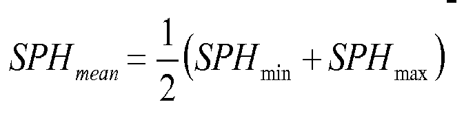
where n is the index of the constituent material of the lens. - As is known, a mean sphere SPHmean at any point on an aspherical surface can also be defined by the formula:
- A cylinder CYL is also defined by the formula

- The characteristics of any complex face of the lens may be expressed by means of the local mean spheres and cylinders. A surface can be considered as locally aspherical when the cylinder is at least 0.25 diopters.
- * The "Base curve" B usually defines the mean sphere of the front surface at a far vision point;
- * The "addition of a surface" may be defined as the mean sphere variation between the near vision reference point (NV) belonging to the near vision zone and the far vision reference point (FV) belonging to the far vision zone. Reference points can be for instance, but not limited to, control points. The addition of the surface can be expressed as:

- If Addsurface > 0, the surface is a progressive surface;
- If Addsurface < 0, the surface is a regressive surface. Thus, reference will be made hereafter to "regression values" as being negative values expressed in diopters.
- By "regressive surface" is meant a continuous aspheric surface having a far vision zone, a near vision zone and a zone of decreasing mean sphere value connecting the far vision and near vision zones. By "progressive surface" is meant a continuous aspheric surface having a far vision zone, a near vision zone and a zone of increasing mean sphere value connecting the far vision and near vision zones.
- Progressive lenses comprise micro-markings that have been made mandatory by a harmonized standard ISO 8990-2. Temporary markings may also be applied on the surface of the lens, indicating positions of control points on the lens, such as a control point for far vision, a control point for near vision; a prism reference point and a fitting cross for instance. If the temporary markings are absents or have been erased, it is always possible to a skilled person to position the control points on the lens by using a mounting chart and the permanent micro-markings.
- The micro-markings also make it possible to define referential for both surfaces of the lens.
- In a case of a progressive power lens, the lens comprises a far vision zone located in the upper part of the lens, a near vision zone located in the lower part of the lens and an intermediate zone situated in the lower part of the lens between the far vision zone and the near vision zone. The "upper" part of the lens corresponds to a negative lowering angle α <0° and the "lower" part of the lens corresponds to a positive lowering angle α >0°. Thus, on the first surface, the "upper" part corresponds to a positive value along the y axis and the "lower" part corresponds to a negative value along the y axis in the frame.
- "central vision" (also referred as "foveal vision") describes the perception of the fovea, a small area in the center of the retina that contains a rich collection of cones. In a central vision situation, an observer adjusts its gaze direction to the object in order to hold the retinal image of the object on the fovea. Central vision permits a person to read, watch TV and perform other activities that require fine and sharp vision;
- a "gaze direction" is defined by two angles measured with regard to reference axes centered on the center of rotation of the eye;
- "peripheral vision" describes the ability to see objects and movement outside of the gaze direction. In a peripheral vision situation, an observer looks in a fixed gaze direction and an object is seen out of this direct line of vision. The direction of a ray coming from the object to the eye is then different from the gaze direction and is referred as peripheral ray direction. Peripheral vision is mainly the perception of the rods, photoreceptor cells located outside the fovea of the retina;
- a "peripheral ray direction" is defined by two angles measured with regard to reference axes centered on the eye entrance pupil and moving along the gaze direction axis;
- "ocular deviation" is defined in central vision and describes the fact that adding a lens causes an eye to rotate in order to stay focused on the same object. The angle can be measured in prismatic diopters;
- "object visual field in central vision" is defined in the object space by the portion of space that the eye can observe scanning an angular portion of the lens determined by at least two gaze directions. For instance, these gaze directions can be defined by the shape of the spectacle frame or by an aberration level that hinders visualizing the object space with a good enough sharpness;
- "image visual field in central vision in the image space" is defined for a determined and fixed object visual field in central vision in the object space (eye space), as the angular portion scanned by the eye to visualize the visual field in the object space;
- "pupil field ray deviation" describes that a ray coming from an object located in the peripheral field of view is modified by adding a lens on its path to the eye entrance pupil;
- "object visual field in peripheral vision" is defined in the object space. It is the portion of space that the eye can observe in the peripheral visual field of view (while the eye is looking in a fixed direction) defined by at least two rays issued from the center of eye entrance pupil. For instance, these rays can be defined by the shape of the spectacle frame or by an aberration level that hinders visualizing the object space with a good enough sharpness;
- "image visual field in peripheral vision" is defined for a determined and fixed peripheral object visual field as the corresponding angular portion in the image space viewed by the peripheral vision of the eye;
- "prismatic deviation in central vision" is defined in the object space by the angular deviation of a ray issued from the center of rotation of the eye introduced by the quantity of prism of the lens;
- "prismatic deviation in peripheral vision" is the angular deviation of a ray issued from the center of the entrance pupil introduced by the quantity of prism of the lens;
- "magnification in central/peripheral vision" is defined as the ratio between the apparent angular size (or the solid angle) of an object seen in central/peripheral vision without lens and the apparent angular size (or the solid angle) of an object seen through the lens in central/peripheral vision;
- "Distortion" is a defect which is not related to the resolution of images impacting the sharpness or the contrast of the image formed by the periphery of the visual field of the lens but merely to their shape. Distortion can be evaluated in different situations of use of the lens. First, a fixation point is imposed to the wearer so that he keeps his eye immobile (thus the gaze direction is fixed). In this case, the distortion which is evaluated is called static vision, i.e. the direction of gaze is fixed and distortion is analyzed in peripheral vision. Distortion can also be evaluated in dynamic vision, i.e. the direction of gaze is free and distortion is analyzed in central vision. Static Distortion is due to the variation of preceding criteria with the peripheral ray direction (pupil field ray deviation and/or magnification in peripheral vision). Dynamic Distortion is due to the variation of preceding criteria with the gaze direction (prismatic deviation and/or magnification in central vision). Evaluation in static or dynamic vision is made depending on the intended use of the lens. Reference can be made to publication « La distortion en optique de lunetterie » by Yves LE GRAND Annales d'Optique Oculaire 5ème année N°1 Janvier 1956.
- "rules", suitable to link at least a visual performance level with at least one optical criterion, refer to a relationship between the said visual performance level and the said optical criterion.
- According to an embodiment, the visual performance level (VPL) of step a) is selected in the list of visual performances levels consisting of a sub-list of visual acuity performances, a sub-list of contrast sensitivity performances, a sub-list of visual space perception performance, a sub-list of reading performance, a sub-list of colour perception performance, a sub-list of self-reported visual performance, or a combination of at least two of said performances. According to the present invention, following wordings refer to further definitions;
- "visual acuity performance" refers to acuteness or clearness of vision, which is dependent on the sharpness of the retinal focus within the eye and the sensitivity of the interpretative faculty of the brain;
- "contrast sensitivity performance" refers to the difference in visual properties that makes an object (or its representation as an image) distinguishable from other objects and the background. In visual perception, contrast is determined by the difference in the color and brightness of the object and other objects within the same field of view;
- "visual space perception" refers to the ability of humans to become aware of the relative position of their own bodies and objects around them. Vision provides cues, such as depth and distance that are important for movement and orientation relative to the environment;
- "reading performance" refers to the ability of looking at and interpreting letters or other information that is written;
- "color perception performance" refers to the ability to distinguish objects based on the wavelengths (or frequencies) of the light;
- "self-reported visual performance" refers to the evaluation by a person of the perceived visual performance in a global way or for different activities and/or different lighting conditions.
- According to embodiments of the invention:
- ● the sub-list of visual acuity performances consists of central visual acuity, peripheral visual acuity, dynamic visual acuity, each of said visual acuity being measured either according to monocular or to binocular vision and to either photopic or mesopic or scotopic vision conditions, or a combination of at least two of said visual acuity performances; and/or
- ● the sub-list of contrast sensitivity performances consists of spatial contrast sensitivity, time contrast sensitivity, or a combination of said contrast sensitivity performances measured either according to monocular or to binocular vision and to either photopic or mesopic or scotopic vision conditions; and/or
- ● the sub-list of "visual space perception" performances consists of distance perception acuteness, stereo acuity, aniseikonia measurement, moving object speed perception, visual field, being measured either photopic or mesopic or scotopic vision conditions, or a combination of at least two of said space perception performances; and/or
- ● the sub-list of "reading performances" consists of reading rate performance, reading comprehension performance, word identification performance, being measured either according to monocular or to binocular vision and to either photopic or mesopic or scotopic vision conditions, or a combination of at least two of said reading performances; and/or
- ● the sub-list of "color perception performances" consists of hue discrimination, saturation discrimination, brightness discrimination Measured either according to monocular or to binocular vision and to either photopic or mesopic or scotopic vision conditions, or a combination at least two of said color perception performances ; and/or
- ● the sub-list of "self-reported visual performances" consists of visual related quality of life questionnaires as National Eye Institute (NEI) Visual Functioning Questionnaire or developed questionnaire on subjective visual performance during defined activities and/or defined conditions or a unique question about self-reported visual performances.
- According to an embodiment at least two visual performance levels are selected and a global visual performance scale is defined.
- According to an example of preceding embodiment, one can determine an average value for each selected visual performance level and calculate a scaled visual performance level as being the ratio between the visual performance level of a viewer divided by the average value of corresponding visual performance level. One can then define a "global" visual performance level based on at least two different visual performance levels where the global visual performance level is defined as being the mean value of the selected scaled visual performance levels.
- According to an example, one considers visual acuity measurements according to far vision and to near vision. If the visual acuity for far vision would be 14/10 and the visual acuity for near vision would be 12/10, the global vision acuity would thus be 13/10.
- Combinations of visual performance levels so as to define a global visual performance level may be following:
- photopic visual acuity and mesopic visual acuity and/or scotopic visual acuity;
- contrast sensitivity and photopic visual acuity (for example in far vision);
- reading rate performance and reading comprehension performance and visual acuity (for example in near vision);
- contrast sensitivity and stereoscopic acuity.
- According to an embodiment, the optical system is selected in optical systems data base wherein all the optical systems of the optical systems data base have been calculating previously taking into account at least a same focalisation criterion over an evaluation zone according to at least a gaze direction.
- According to an embodiment the physical and geometrical parameters of step c) are calculated by computer means thanks to an optimization method wherein at least a focalisation criterion(a) over an evaluation zone according to at least a gaze direction is taken into account to implement the calculation. A focalisation criterion aims at improving optical quality of the image caused by optical aberrations that induce blurring in the image, drop in contrast and causing therefore unclear vision.
- Optimization methods are commonly used in the field of ophthalmic lens design.
- These methods are known by the one skilled in the art, for example in the publication " Application of optimization in computer-aided ophthalmic lens design" (P. Allione, F.Ahsbahs and G. Le Saux, in SPIE Vol. 3737, EUROPTO Conference on Design and Engineering of Optical Systems, Berlin, May 1999), which is incorporated by reference in the present document. Examples of optimization methods are also disclosed in patent literature, such as in
US 6,382,789 ,WO 2010/043704 ,W02010/076294 . - According to an embodiment the focalisation criterion is selected in the list consisting of optical power, astigmatism, High Order Aberration, Strehl ratio, Root Means Square (RMS), drop in acuity or contrast. For example, the drop in acuity or contrast can be estimated from models taking into account central vision criteria, as power error or astigmatism such as disclosed in FAUQUIER C., BONNIN T., MIEGE C., ROLAND E.: Influence of Combined Power Error and Astigmatism on Visual Acuity, Vision Science and its applications (VSIA), Santa Fe NM (USA), 2-7 fév. 1995".
- According to an embodiment of the invention the personalized optical system characterizing in a progressive addition spectacle lens wherein the front and the back surfaces may be progressive or regressive addition surfaces and wherein the geometrical factor Q = ADDF/ADD is a parameter used to meet the set of rules according to step c); ADDF being the addition of the front surface and ADD being the optical addition of the lens.
- According to another embodiment the personalized optical system characterises a progressive addition spectacle lens and wherein the "base curve" of the spectacle ophthalmic lens is a parameter used to meet the set of rules according to step c).
- According to still another embodiment the personalized optical system characterises a progressive addition spectacle lens and wherein refractive index is a physical parameter used to meet the set of rules according to step c) .
- According to different embodiments of the present invention, the rules of the set of rules of step b) are chosen within the list consisting of:
- ● providing a desired target value for at least a chosen optical criterion as a function of the value of the visual performance level value of step a);
- ● providing an equality or an inequality equation or a relationship between target values of the same optical criteria evaluated over at least two evaluation zones as a function of the value of the visual performance level value of step a);
- ● providing a trend relationship between at least two chosen optical criteria as a function of the value of the visual performance level value of step a).
- an "evaluation zone" is associated with a local criterion to be evaluated; it is composed of one or several evaluation domains. An evaluation domain is composed of one or several gaze directions for a criterion belonging to the central vision optical criteria (CVOC) group or to the geometrical local criteria group and of one or several peripheral ray directions for a criterion belonging to the peripheral vision optical criteria group (PVOC);
- a "target value" is a value to be reached by a criterion. When the selected criterion is a local criterion, a target value is associated to an evaluation domain. When the selected criterion is a global criterion, a target value is associated to the whole optical system.
- According to an embodiment of the present invention:
- ● the visual performance level of step a) is chosen in the sub-list of visual acuity performance, and
- ● an optical criterion of step b) is chosen within the visual field list consisting of object visual field in central vision, image visual field in central vision, object visual field in peripheral vision, image visual field in peripheral vision and another optical criterion of step b) is chosen within the magnification list consisting of magnification in central vision, magnification in peripheral vision, and
- ● the rule linking the preceding visual performance level and the two preceding optical criteria is a trend relationship where the highest is the visual acuity performance level of the eye of the wearer, the highest is the value of the optical criterion chosen in the visual field list and that respectively the lowest is the visual acuity performance level of the eye of the wearer, the highest is the value of the optical criterion chosen in the magnification list.
- The invention is also directed to a method for manufacturing a spectacle ophthalmic lens for a wearer, the method comprising the following steps:
- aa) providing the physical and geometrical parameters of a personalized optical system according to any of preceding claims;
- bb) providing a lens substrate;
- cc) manufacturing the spectacle ophthalmic lens according to the parameters of step aa).
- The invention is also directed to a computer program product comprising one or more stored sequence of instruction that is accessible to a processor and which, when executed by the processor, causes the processor to carry out the step c) of present invention and optionally the other steps of any of here above mentioned embodiments.
- The invention is also directed to a computer-readable medium carrying one or more sequences of instructions of the preceding computer program product(s).
- Unless specifically stated otherwise, as apparent from the following discussions, it is appreciated that throughout the specification discussions utilizing terms such as "computing", "calculating" "generating", or the like, refer to the action and/or processes of a computer or computing system, or similar electronic computing device, that manipulate and/or transform data represented as physical, such as electronic, quantities within the computing system's registers and/or memories into other data similarly represented as physical quantities within the computing system's memories, registers or other such information storage, transmission or display devices.
- Embodiments of the present invention may include apparatuses for performing the operations herein. This apparatus may be specially constructed for the desired purposes, or it may comprise a general purpose computer or Digital Signal Processor ("DSP") selectively activated or reconfigured by a computer program stored in the computer. Such a computer program may be stored in a computer readable storage medium, such as, but is not limited to, any type of disk including floppy disks, optical disks, CD-ROMs, magnetic-optical disks, read-only memories (ROMs), random access memories (RAMs) electrically programmable read-only memories (EPROMs), electrically erasable and programmable read only memories (EEPROMs), magnetic or optical cards, or any other type of media suitable for storing electronic instructions, and capable of being coupled to a computer system bus.
-
Figure 1 shows a schematic view of a lens plus eye system. -
Figure 2 shows a ray tracing from the center of rotation of the eye. -
Figure 3 shows a ray tracing from the center of the eye entrance pupil. -
Figure 4 illustrates horizontal object visual field. -
Figures 5a and b illustrate addition of a surface. -
Figures 6 to 10 relate to a first embodiment according to the present invention. -
Figures 11 to 17 relate to a second embodiment according to the present invention. -
Figures 18 and 19 relate to a third embodiment according to the present invention. - Skilled artisans appreciate that elements in the figures are illustrated for simplicity and clarity and have not necessarily been drawn to scale. For example, the dimensions of some of the elements in the figures may be exaggerated relative to other elements to help improve the understanding of the embodiments of the present invention. Same reference on different figures refers to the same object.
-
Figure 1 illustrates a schematic view of a lens-plus-eye system. Thelens 10 has afront face 110 and a rear (or back)face 120. Referring tofigure 1 , an eye position can be defined by the center of rotation of the eye, CRE, and the entrance pupil central point P. PS is the pupil size (not drawn to scale). The distance q' between the CRE and thelens 10 is generally, but not limited to, set to 25.5 mm, and p' defines the position of the eye entrance pupil with respect to the CRE. -
Figure 2 illustrates a model for central vision in the purpose of assessing a criterion in a central vision situation by ray tracing. In a central vision situation, the eye rotates about its center of rotation as well as the entrance pupil of the eye. A gaze direction is defined by two angles (α, β) measured with regard to reference axes R=(X,Y,Z) centered on the CRE. For assessing a central vision criterion in a gaze direction (α,β), agaze ray 1 is built from the CRE in the gaze direction (α,β). 11 is the incident ray after passing through thelens 10. -
Figure 3 illustrates a model for peripheral vision in the purpose of assessing a criterion in a peripheral vision situation through ray tracing. In a peripheral vision situation, a gaze direction (α,β) (not represented here) is fixed, and an object is viewed in a peripheral ray direction different from the gaze direction. A peripheral ray direction is defined by two angles (α',β') measured with regard to reference axes R'=(X',Y',Z') centered on the eye entrance pupil and moving along the gaze direction axis given by the fixed direction (α,β) and represented by axis X' onfigure 3 . For assessing a peripheral vision criterion in a peripheral ray direction (α',β'), aperipheral ray 2 is built from the center of the pupil P in a peripheral ray direction (α',β') , 12 is the emergent peripheral ray corresponding to the incidentperipheral ray 10. - According to the gaze ray 1 (in central vision) or to the peripheral ray 2 (in peripheral vision), the ray-tracing software computes the corresponding emergent ray, alternatively under
reference figures 2 and3 . Then, an object point is chosen on the ray in the object space and from this object a pencil of rays is built to calculate the final image. Ray tracing enables then to compute the selected criteria. -
Figure 4 illustrates an example of visual field VF in central vision for tworays lens 10 is represented as a surface with isoastigmatism lines 101-106.Rays predetermined isoastigmatism lines ray 41 along direction (α,β1) andray 51 along direction (α,β2). The object visual field VF in central vision is a function of prismatic deviation and can be mathematically expressed for two rays as:
- Dp_H(α,β1) represents horizontal prismatic deviation in the gaze direction (α,β1) . Horizontal prismatic deviation is the component of the prismatic deviation in a horizontal plane.
- Dp_H(α,β2) represents horizontal prismatic deviation in the gaze direction (α, β2) .
-
Figures 5a and b illustrate addition of respectively the front surface (forexample reference 110 offigure 1 ) and of the back surface (120 of figure e1) of a progressive addition spectacle ophthalmic lens, where the variation of the sphere value Sph (in Diopter) (respectively 210, 220) is represented according to the Y axis. -
Zones zones zones - According to the examples of
figures 5a and 5b both front and back surfaces are progressive surfaces and the resulting addition of a lens having said both surfaces would be about ADD = ADDF + ADDB. - According to the present invention a parameter Q is defined where Q = ADDF / ADD.
-
Figures 6 to 10 relate to a first example of an embodiment of the method according to the present invention. - According to this example, the visual performance level of step a) of the method of the invention is the central visual acuity measured according to binocular vision and two optical criteria of step b) of the method of the invention are chosen directed to object visual field in central vision and to magnification in central vision.
- According to said example, the object visual field in central vision is considered in the near vision zone.
-
Figures 6 and 7 show how said parameter is evaluated; the field to be considered refers to a field which incorporates rays passing through the CRE in directions defined for a given α value and for a β range Δβ. - α is chosen so as the rays passing through the CRO meet the near vision zone. For said example, α = - 34°, and Δβ = 20° for a central β value of 6° (thus β ranges from -4° to + 16°).
- The vision field situated between the CRO and
lens 10 is the near vision image vision field (NV-IVF), equal to Δβ and the vision field seen after passing throughlens 10 is the near vision object vision field (NV-OVF). - For the purpose of the demonstration, one chooses a
lens 10 which fits a prescription where the prescribed dioptric power in far vision is -3 Diopter, the prescribed astigmatism is 0 in far vision and the addition is + 2 Diopters. - One further considers the case where the repartition of the addition between the front and the back surfaces is a parameter used to meet a set of rules according to step c) of the method of the invention.
- A plurality of ophthalmic lens optical systems has been evaluated and results are reported on
figures 8 to 10 where: - In
figure 8 ,curve 80 corresponds to the variation of NV-OVF as a function of Q for NV-IVF constant; - In
figure 9 ,curve 90 corresponds to the variation of the near vision magnification, NV-M, as a function of Q. - In
figure 10 ,curve 100 corresponds to Q variation as a function of central visual acuity measured according to binocular vision. - Values presented in those figures relate to optical system characteristics that have been calculated by computer means thanks to an optimization method wherein at least a focalisation criterion over an evaluation zone according to at least a gaze direction is taken into account to implement the calculation.
- The calculated optical systems of the example have been obtained thanks to following steps:
- performance definitions of optical system targets where, for each gaze direction within a 40° vision cone, performances are defined regarding focalisation criteria consisting of optical power and astigmatism (meaning that for each gaze direction an optical power and an astigmatism values are attributed);
- optimization where the generated optical systems have a variable addition between the front and the back faces (Q variation), but are calculated so as the optical performances are substantially the same regarding optical power and astigmatism values; therefore in each gaze direction the calculation is done so that the tolerance regarding optical power value is equal or less than 0,05 diopters and regarding the astigmatism value is equal or less than 0.1 diopters; according to said calculations, the optical power and astigmatism values of the different optical systems are substantially the same, but criteria regarding visual field and magnification may vary from an optical system to another one.
- Results of said calculations are presented on
figures 8 to 10 . -
Figure 8 shows the variation of the calculated near vision object visual field (NV-OVF, in degrees) according to the Q factor. -
Figure 9 shows the variation of the calculated near vision magnification according to the Q factor. - Said curves demonstrate that NV-OVF and NV-M vary according to opposite trends as a function of the Q factor.
-
Figures 8 and9 demonstrate that one can offer ophthalmic spectacle lens optical systems where the optical performance regarding optical power and astigmatism values are substantially the same, but where visual field and magnification may significantly vary. - Thanks to variation of visual field and magnification for given optical power and astigmatism values, one can provide optical system suitable to meet the needs of a specific wearer.
- Said needs can be linked to a visual performance level of the wearer.
- Therefore and according to the present invention, one proposes to improve the visual comfort of the wearer thanks to increasing the magnification value (near vision magnification according to the present example) when the wearer's acuity is low so that the wearer can more easily take into account object image details; one also proposes to improve the visual comfort of the wearer thanks to enlarging his vision field (near vision object visual field according to the present example) when the wearer's acuity is high so that the wearer can more easily scan his environment.
- According to the present example, said balance between vision field and magnification can be obtained thanks to varying the repartition of the addition between the front and the back surface (Q factor). Thus the Q factor can be chosen as a parameter used to meet the set of rules according to step c) of the process according to the invention.
- An example of a said rule is illustrated in
figure 10 where the chosen Q factor (ordinate) is determined as a function of the maximal corrected central vision acuity measured according to binocular vision (abscissa). - For wearers which acuity is low (equal or less than 8/10), one suggests to choose a Q factor equal to 2, meaning that, according to
figures 8 and9 , a high NV-M value is preferred and according to the present example NV-OVF = 21.6° and NV-M = 0,95. - For wearers whose acuity is high (equal or more than 14/10), one suggests to choose a Q factor equal to -2 meaning that a high NV-OVF value is preferred, and according to the present example NV-OVF = 22,10° and NV-M = 0,91.
- For wearers whose acuity is medium, one suggest to find a compromise between the two said optical parameters where the Q factor varies linearly between the two preceding values. Thus and according to the present example ,one choose Q = -1 for an intermediate acuity equal to 12.5/10 thus NV-OVF = 22.0° and NV-M = 0.92.According to a second example of the method according to the present invention, one aims to obtain optimized optical systems when considering both far vision and near vision.
- Evaluation zones are defined according to
figures 11 and 12 , both for far vision and near vision zones. According to the present example ΔβNV = ΔβFV = 20° centered around β = 6° for βNV and centered around β = 0° for βFV. - α values are following : αNV = 34° and αFV = -8°.
- Optimisation process is implemented according to the rules described regarding the preceding example.
- For the present example the prescription of the wearer is sphere -3 in far vision, the astigmatism is 0 in far vision and the addition is 2.
-
Figures 13 and14 show the variation of respectively magnification parameters and object visual field parameters according to the Q factor and to the base curve B of the optical system. -
Figure 13 shows calculated curves regarding magnification parameters as referred in table 1 where the number of the curve is defined according to the base curve B and to the vision zone.Table 1 Base curve B (Diopter) Near vision NV-M Far vision FV-M 1.75 136 135 2.75 132 131 3.75 134 133 -
Figure 14 shows calculated curves regarding vision field parameters referred in table 2 where the number of the curve is defined according to the base curve B and to the vision zone.Table 2 Base curve β Far vision FV-OVF Near vision NV-OVF 1.75 145 146 2.75 141 142 3.75 143 144 -
Figure 13 teaches that far vision or near vision magnification (respectively FV-M and NV-M) vary according to different trends when considering the Q factor and the base curve value. - FV-M and NV-M increase when the base curve value increases, for a constant Q factor value.
- The FV-M(Q) curves are almost parallel one to another when the base curve value varies.
- Same applies for NV-M(Q).
- NV-M values increase, for a same base curve value when the Q factor increases, where FV-M values are almost constant, for a same base curve value, as a function of the Q factor.
-
Figure 14 teaches that far vision or near vision object visual field (respectively FV-OVF and NV-OVF) vary according to different trends when considering the Q factor and the base curve value. - FV-OVF and NV-OVF decrease when the base curve value increases, for a constant Q factor value.
- The FV-OVF (Q) curves are almost parallel one to another when the base curve value varies.
- Same applies for NV-OVF(Q).
- NV-OVF values decreases, for a same base curve value when the Q factor increases, where FV-OVF values are almost constant for a same base curve value, as a function of the Q factor.
- Thanks to said curves, one can offer to a wearer an optimized optical system when choosing an adapted base curve value and Q factor value according to his visual acuity.
- One can make the assumption that the global visual perception of a wearer which visual acuity is more than 14/10 is only limited by object visual field. For such wearers, an optimized solution would be offering an optical system where object visual fields are the largest, both for near and far visions. Thanks to the teachings of
figures 13 and14 , one will choose an optical system where the base curve value is 1.75 and the Q factor is -2. - On the opposite side, one can make the assumption that the global visual perception of a wearer which visual acuity is less than 8/10 is only limited by magnification. For such wearers, an optimized solution would be offering an optical system where magnification is the largest, both for near and far vision.
- Thanks to the teaching of
figures 13 and14 , one will choose an optical system where the base curve is 3.75 and the Q factor is 2. - For wearers which visual acuity is between 8/10 and 14/10, one will suggest different routes taking into account the here above mentioned parameters.
- According to an embodiment, one defines two weighting factors, one directed to magnification FM and the other one directed to object visual field FOVF. Each weighing factor, F, varies between 0 and 1.
- When considering a range of magnification or object visual field values calculated according to different parameters, such as the base curve value and/or the Q factor value, one will choose an optical system where:

and
- where "max" refers to the highest value calculated for magnification, respectively object visual field when varying the parameter(s) within a chosen range and "min" refers to corresponding lowest value.
- For wearers which visual acuity is equal or less than 8/10, one will define FM = 1 and FOVF = 0.
- For wearers which visual acuity is equal or more than 14/10, one will define FM = 0 and FOVF = 1
- Between said two cases, one will choose a F factor according to
figure 15 where the abscissa relates to visual acuity and ordinate to the weighing factor F. -
Curve 151 represents the variation of FOVF andcurve 152 represents the variation of FM, according to visual acuity. - Dotted lines regard an example where the wearer's visual acuity is 12. Thanks to
figure 15 one determines FM = 0.33 and FOVF = O.67. - Following values are then determined:
- FV-M = 0.86
- NV-M = 0.94
- FV-OVF = 22.63°
- NV-OVF = 21.71°
- Results are reported on the data of
figures 13 and14 as shown onfigures 16 and 17 , where one can determine that the best optical system for said wearer relates to a base curve value of 2.75 and a Q factor equal to 1. -
Figures 18 and 19 relate to a third example of an embodiment according to the present invention where one aims to offer another approach to the problem addressed according to the first example according to the invention. Then according to said third example object visual field in central vision is considered in the near vision zone (as illustrated onfigures 6 and 7 ). - According to said example, one let geometrical parameters of the optical system vary so as to let the Q factor value vary according to visual acuity. Constraints regarding optical power and astigmatism are released to let the optimization according to magnification and object visual field be more efficient.
- According to following example, a plurality of wearers have the same prescription, where the prescribed dioptric power in far vision is -3 Diopter, the prescribed astigmatism is 0 Diopter in far vision, and the addition is 2.
- Different optical systems have been evaluated where the Q factor is taken into account according to following steps:
- optical system target performances are defined where, for each gaze direction within a vision cone of 40°, performances are specified for optical power and for astigmatism;
- optimization is implemented wherein all the generated optical systems have different addition repartition between front and back surfaces (i.e. different Q factor values); optimization is made in each gaze direction so as the tolerance regarding optical power value is equal or less than 0.3 and regarding the astigmatism value is equal or less to 0.3 (said tolerance values were respectively 0.05 and 0.1 according to the first example).
- Other steps are similar to those of the first example.
- One will then generate a plurality of optical systems which are in the vicinity of those according to the first example but differ because the weight on focalisation criteria (optical power and astigmatism)compared to the weight of optical criteria (object vision field and/or magnification) is lowered in the present example compared to the first example.
Table 3 reports data used to calculate two examples of optical system and corresponding results according to the first example and the third example of embodiments according to the present invention. The optical system is referred as (x, y) where x corresponds to an optical system example and y corresponds to associated Q factor (which is equal to 2 or -2 according to the present optical system examples).Table 3 Example of embodiment Optical system Optical power Astigmatism NV-M final NV-OVF final (°) Target Final value Target Final value 1 (1,2) -0.7±0.05 - 0.68 0±0.1 0.06 0.948 21.59 1 (2,-2) -0.7±0.05 - 0.74 0±0.1 0.1 0.908 22.10 3 (1,2) -0.7±0.3 - 0.83 0±0.3 0.24 0.941 21.76 3 (2,-2) -0.7±0.3 - 0.97 0±0.3 0.26 0.891 22.23 -
Figures 18 and 19 show the results according to the first example of an embodiment (results offigures 8 and9 are reported) compared to those of the present third example of an embodiment of the invention, where near vision object visual field results as a function of the Q factor are reported onfigure 18 and results of near vision magnification as a function of the Q factor is reported onfigure 19 . - Thanks to releasing tolerances regarding the optical power value and the astigmatism value, one can offer largest object visual fields or highest M for the wearer for the same Q factor value compared to the first example of an embodiment.
- One can than offer to a wearer an optimized optical system based on the set of optical systems determined according to said third example of an embodiment and where the selection is made according to the former teaching of the first example of an embodiment of the present invention.
- It is clear that it is possible to employ other methods of optimization, and other ways of representing surfaces differing from the method proposed.
- The invention has been described above with the aid of embodiments without limitation of the general inventive concept. In particular the present invention provides a method for calculating by optimization an optical system, the optical system being all kinds of optical lenses, particularly ophthalmic lenses, e.g. single vision (spherical, torical), bi-focal, progressive, aspherical lenses (etc.) .
Claims (15)
- A method at least partly implemented by computer means for providing a personalized optical system for a wearer wherein the optical system characterizes an ophthalmic lens for said wearer according to his prescription data, the said method comprising the following steps:a) providing a visual performance level (VPL) value of at least one eye of the wearer, with the provision that prescription data (Rx) consisting of sphere, cylinder, axis, addition, prism are not defined as a visual performance level;b) providing a set of rules linking at least the visual performance level of step a) with at least one optical criterion chosen among one or both of the two following optical criteria groups consisting of
● central vision optical criterion (CVOC) group consisting of prismatic deviation in central vision, ocular deviation, object visual field in central vision, image visual field in central vision, magnification in central vision or a variation of preceding criteria;
● peripheral vision optical criterion (PVOC) group consisting of pupil field ray deviation, object visual field in peripheral vision, image visual field in peripheral vision, prismatic deviation in peripheral vision, magnification in peripheral vision, or a variation of preceding criteria;c) calculating by computer means the physical and geometrical parameters of the personalized optical system that meets the prescription data of the wearer or selecting the personalized optical system in an optical systems data base comprising a plurality of optical systems that meet the prescription data of the wearer, so that to meet the set of rules of step b) according to the visual performance level data provided in step a). - The method according to preceding claim wherein the visual performance level (VPL) of step a) is selected in the list of visual performances levels consisting of a sub-list of visual acuity performances, a sub-list of contrast sensitivity performances, a sub-list of visual space perception performance, a sub-list of reading performance, a sub-list of colour perception performance,a sub-list of self-reported visual performance, or a combination of at least two of said performances.
- The method according to preceding claim wherein:● the sub-list of visual acuity performances consists of central visual acuity, peripheral visual acuity, dynamic visual acuity, each of said visual acuity being measured either according to monocular or to binocular vision and to either photopic or mesopic or scotopic vision conditions, or a combination of at least two of said visual acuity performances; and/or● the sub-list of contrast sensitivity performances consists of spatial contrast sensitivity, time contrast sensitivity, or a combination of said contrast sensitivity performances measured either according to monocular or to binocular vision and to either photopic or mesopic or scotopic vision conditions; and/or● the sub-list of "visual space perception" performances consists of distance perception acuteness, stereo acuity, aniseikonia measurement, moving object speed perception, visual field, being measured either photopic or mesopic or scotopic vision conditions, or a combination of at least two of said space perception performances; and/or● the sub-list of "reading performances" consists of reading rate performance, reading comprehension performance, word identification performance, being measured either according to monocular or to binocular vision and to either photopic or mesopic or scotopic vision conditions, or a combination of at least two of said reading performances; and/or● the sub-list of "color perception performances" consists of hue discrimination, saturation discrimination, brightness discrimination measured either according to monocular or to binocular vision and to either photopic or mesopic or scotopic vision conditions, or a combination of at least two of said color perception performances; and/or● the sub-list of "self-reported visual performances" consists of visual related quality of life questionnaires as National Eye Institute (NEI) Visual Functioning Questionnaire or developed questionnaire on subjective visual performance during defined activities and/or defined conditions or a unique question about self-reported visual performances.
- The method according to claim 2 or to claim 3 wherein at least two visual performance levels are selected and wherein a global visual performance scale is defined.
- The method according to any of preceding claims wherein the optical system is selected in optical systems data base and wherein all the optical systems of the optical systems data base have been calculating previously taking into account at least a same focalisation criterion over an evaluation zone according to at least a gaze direction.
- The method according to any of claims 1 to 4 wherein the physical and geometrical parameters of step c) are calculated by computer means thanks to an optimization method wherein at least a focalisation criterion(a) over an evaluation zone according to at least a gaze direction is taken into account to implement the calculation.
- The method according to claim 5 or to claim 6 wherein the focalisation criterion is selected in the list consisting of optical power, astigmatism, High Order Aberration (HOA), Strehl ratio, Root Means Square (RMS), drop in acuity or contrast.
- The method according to any of claims 1 to 7 wherein the personalized optical system characterizing a progressive addition spectacle lens wherein the front and the back surfaces may be progressive or regressive addition surfaces and wherein the geometrical factor Q = ADDF/ADD is a parameter used to meet the set of rules according to step c), ADDF being the addition of the front surface and ADD being the optical addition of the lens.
- The method according to any of claims 1 to 7 wherein the personalized optical system characterises a progressive addition spectacle lens and wherein the "base curve" of the spectacle ophthalmic lens is a parameter used to meet the set of rules according to step c).
- The method according to any of claims 1 to 7 wherein the personalized optical system characterises a progressive addition spectacle lens and wherein refractive index is a physical parameter used to meet the set of rules according to step c).
- The method according to any of preceding claims wherein rules of the set of rules of step b) are chosen within the list consisting of:● providing a desired target value for at least a chosen optical criterion as a function of the value of the visual performance level value of step a);● providing an equality or an inequality equation or a relationship between target values of the same optical criteria evaluated over at least two evaluation zones as a function of the value of the visual performance level value of step a).● providing a trend relationship between at least two chosen optical criteria as a function of the value of the visual performance level value of step a);
- The method of preceding claim wherein:● the visual performance level of step a) is chosen in the sub-list of visual acuity performance, and● an optical criterion of step b) is chosen within the visual field list consisting of object visual field in central vision, image visual field in central vision, object visual field in peripheral vision, image visual field in peripheral vision and another optical criterion of step b) is chosen within the magnification list consisting of magnification in central vision, magnification in peripheral vision, and● the rule linking the preceding visual performance level and the two preceding optical criteria is a trend relationship where the highest is the visual acuity performance level of the eye of the wearer, the highest is the value of the optical criterion chosen in the visual field list, and that respectively the lowest is the visual acuity performance level of the eye of the wearer, the highest is the value of the optical criterion chosen in the magnification list.
- A method for manufacturing a spectacle ophthalmic lens for a wearer, the method comprising the following steps:aa) providing the physical and geometrical parameters of a personalized optical system according to any of preceding claims;bb) providing a lens substrate;cc) manufacturing the spectacle ophthalmic lens according to the parameters of step aa).
- A computer program product comprising one or more stored sequence of instruction that is accessible to a processor and which, when executed by the processor, causes the processor to carry out the step c) of claim 1 and optionally the other steps of any of claims 1 to 13.
- A computer-readable medium carrying one or more sequences of instructions of the computer program product of claim 14.
Priority Applications (7)
| Application Number | Priority Date | Filing Date | Title |
|---|---|---|---|
| EP12305594.9A EP2669732A1 (en) | 2012-05-30 | 2012-05-30 | A method for providing a personalized spectacle lens optical system for a wearer |
| EP13725712.7A EP2856247B1 (en) | 2012-05-30 | 2013-05-30 | A method for providing a personalized spectacle lens optical system for a wearer |
| JP2015514501A JP2015519606A (en) | 2012-05-30 | 2013-05-30 | Method for providing wearer's personal eyeglass lens optics |
| US14/401,747 US9733489B2 (en) | 2012-05-30 | 2013-05-30 | Method for providing a personalized spectacle lens optical system for a wearer |
| PCT/EP2013/061179 WO2013178740A1 (en) | 2012-05-30 | 2013-05-30 | A method for providing a personalized spectacle lens optical system for a wearer |
| AU2013269656A AU2013269656A1 (en) | 2012-05-30 | 2013-05-30 | A method for providing a personalized spectacle lens optical system for a wearer |
| CN201380028811.6A CN104335103B (en) | 2012-05-30 | 2013-05-30 | A method for providing a personalized spectacle lens optical system for a wearer |
Applications Claiming Priority (1)
| Application Number | Priority Date | Filing Date | Title |
|---|---|---|---|
| EP12305594.9A EP2669732A1 (en) | 2012-05-30 | 2012-05-30 | A method for providing a personalized spectacle lens optical system for a wearer |
Publications (1)
| Publication Number | Publication Date |
|---|---|
| EP2669732A1 true EP2669732A1 (en) | 2013-12-04 |
Family
ID=48536917
Family Applications (2)
| Application Number | Title | Priority Date | Filing Date |
|---|---|---|---|
| EP12305594.9A Withdrawn EP2669732A1 (en) | 2012-05-30 | 2012-05-30 | A method for providing a personalized spectacle lens optical system for a wearer |
| EP13725712.7A Active EP2856247B1 (en) | 2012-05-30 | 2013-05-30 | A method for providing a personalized spectacle lens optical system for a wearer |
Family Applications After (1)
| Application Number | Title | Priority Date | Filing Date |
|---|---|---|---|
| EP13725712.7A Active EP2856247B1 (en) | 2012-05-30 | 2013-05-30 | A method for providing a personalized spectacle lens optical system for a wearer |
Country Status (6)
| Country | Link |
|---|---|
| US (1) | US9733489B2 (en) |
| EP (2) | EP2669732A1 (en) |
| JP (1) | JP2015519606A (en) |
| CN (1) | CN104335103B (en) |
| AU (1) | AU2013269656A1 (en) |
| WO (1) | WO2013178740A1 (en) |
Cited By (4)
| Publication number | Priority date | Publication date | Assignee | Title |
|---|---|---|---|---|
| WO2016091853A1 (en) * | 2014-12-08 | 2016-06-16 | Essilor International (Compagnie Generale D'optique) | A method implemented by computer means for calculating a lens optical system of a spectacle ophthalmic lens for a wearer |
| WO2018220508A3 (en) * | 2017-05-30 | 2019-02-21 | Zingara Limited | Device and method for the evaluation of visual abilities |
| WO2019105906A1 (en) * | 2017-11-30 | 2019-06-06 | Essilor International | Set of ophthalmic lenses |
| EP3534203A4 (en) * | 2016-10-31 | 2020-05-20 | Nikon-Essilor Co., Ltd. | PAIR OF PROGRESSIVE POWER GLASSES, METHOD FOR DESIGNING A PAIR OF PROGRESSIVE POWER GLASSES, AND METHOD FOR MANUFACTURING A PAIR OF PROGRESSIVE POWER GLASSES |
Families Citing this family (26)
| Publication number | Priority date | Publication date | Assignee | Title |
|---|---|---|---|---|
| US9995948B2 (en) | 2014-05-11 | 2018-06-12 | AddOn Optics Ltd. | Adhesive optical film to convert an eyeglass lens to a progressive lens |
| US10849490B2 (en) * | 2015-08-25 | 2020-12-01 | Indiana University Research And Technology Corporation | Systems and methods for specifying the quality of the retinal image over the entire visual field |
| US10614108B2 (en) * | 2015-11-10 | 2020-04-07 | International Business Machines Corporation | User interface for streaming spoken query |
| JP6247722B1 (en) * | 2016-06-29 | 2017-12-13 | 株式会社東海メガネコンタクト | Diopter value prediction system, diopter value prediction method and program |
| IL269159B2 (en) * | 2017-03-05 | 2024-09-01 | Virtuoptica Ltd | Method and device for visual inspection |
| EP3420887B1 (en) * | 2017-06-30 | 2025-01-29 | Essilor International | Method for determining the position of the eye rotation center of the eye of a subject, and associated device |
| EP3438606A1 (en) * | 2017-08-04 | 2019-02-06 | Essilor International | Method for determining an optical system, and ophthalmic lens and ophthalmic filter determined by said method |
| EP3454110B1 (en) * | 2017-09-11 | 2022-10-05 | Rupp + Hubrach Optik GmbH | Progressive addition lens and method for manufacturing thereof |
| EP3727128B1 (en) * | 2017-12-21 | 2026-02-11 | Sorbonne Université | A method of analyzing a visual field of an individual |
| DE102018002630B4 (en) * | 2018-03-29 | 2024-03-28 | Rodenstock Gmbh | Alignment of subjective and objective refractions |
| WO2019193120A1 (en) * | 2018-04-06 | 2019-10-10 | Essilor International | Method for customizing a head mounted device adapted to generate a virtual image |
| EP3586720A1 (en) * | 2018-06-29 | 2020-01-01 | Carl Zeiss Vision International GmbH | Method for optimising an optical aid using automatic determination of subjective vision |
| EP3887896B1 (en) * | 2018-11-30 | 2024-03-06 | Essilor International | Method for determining a progressive lens and associated system |
| CN113508330B (en) * | 2019-03-29 | 2023-07-28 | 豪雅镜片泰国有限公司 | Method for measuring perception ability of glasses of subject and method for designing progressive-power lens |
| CN110346946B (en) * | 2019-06-25 | 2020-11-10 | 苏州科技大学 | Method for detecting spectacle lens based on individual characteristics of spectacle wearer |
| ES2965618T3 (en) * | 2019-07-04 | 2024-04-16 | Vivior Ag | Technique to determine a myopia risk indicator |
| EP3761104A1 (en) * | 2019-07-04 | 2021-01-06 | Essilor International | Optical system |
| US12416820B2 (en) | 2019-09-26 | 2025-09-16 | AddOn Optics Ltd. | Progressive lens and manufacture thereof |
| US11378821B2 (en) | 2019-09-26 | 2022-07-05 | AddOn Optics Ltd. | Progressive lens and method of manufacture thereof |
| CN111062328B (en) * | 2019-12-18 | 2023-10-03 | 中新智擎科技有限公司 | An image processing method, device and intelligent robot |
| JP2023514554A (en) | 2020-02-16 | 2023-04-06 | アドオン オプティクス リミティッド | Determining Progressive Lens Optical Design |
| CN115635692B (en) | 2020-03-31 | 2025-12-23 | 艾得安光学有限公司 | Ophthalmic lens shaping |
| EP4157146A1 (en) | 2020-06-01 | 2023-04-05 | Icares Medicus, Inc. | Double-sided aspheric diffractive multifocal lens, manufacture, and uses thereof |
| EP4044081A1 (en) * | 2021-02-12 | 2022-08-17 | Essilor International | A device and method for evaluating a performance of a visual equipment |
| US12456612B2 (en) | 2021-08-16 | 2025-10-28 | AddOn Optics Ltd. | Apparatus and methods for applying vacuum-plasma treatment |
| WO2024192245A1 (en) * | 2023-03-14 | 2024-09-19 | Indizen Optical Technologies S.L. | Ophthalmic lenses with optimized visual performance |
Citations (5)
| Publication number | Priority date | Publication date | Assignee | Title |
|---|---|---|---|---|
| US6382789B1 (en) | 1998-09-28 | 2002-05-07 | Essilor International | Toric ophthalmic lenses |
| WO2005091054A1 (en) * | 2004-03-18 | 2005-09-29 | Essilor International (Compagnie Generale D'optique) | Progressive addition lenses with adjusted image magnification |
| WO2010043704A1 (en) | 2008-10-16 | 2010-04-22 | Essilor International (Compagnie Generale D'optique) | Optical system determination according to advanced criteria |
| WO2010076294A1 (en) | 2008-12-31 | 2010-07-08 | Essilor International (Compagnie Generale D'optique) | Method for calculating a system, for example an optical system |
| EP2442171A2 (en) * | 2010-10-12 | 2012-04-18 | Seiko Epson Corporation | Spectacle lens, spectacles, and method for manufacturing spectacle lens |
Family Cites Families (7)
| Publication number | Priority date | Publication date | Assignee | Title |
|---|---|---|---|---|
| FR2874709B1 (en) * | 2004-08-27 | 2006-11-24 | Essilor Int | METHOD FOR DETERMINING A PAIR OF PROGRESSIVE OPHTHALMIC LENSES |
| FR2894688B1 (en) * | 2005-12-13 | 2008-02-15 | Essilor Int | METHOD FOR DETERMINING A SET OF PROGRESSIVE MULTIFOCAL OPHTHALMIC LENSES |
| FR2898993B1 (en) * | 2006-03-24 | 2008-08-01 | Essilor Int | METHOD FOR DETERMINING A PROGRESSIVE OPHTHALMIC LENS |
| EP2395386A4 (en) * | 2009-02-05 | 2015-09-02 | Hoya Corp | Eyeglass lens evaluation method, eyeglass lens design method, eyeglass lens manufacturing method, eyeglass lens manufacturing system, and eyeglass lens |
| AU2010305423B2 (en) * | 2009-10-07 | 2015-08-13 | Essilor International | An optical function determining method |
| JP5415233B2 (en) * | 2009-11-13 | 2014-02-12 | ホーヤ レンズ マニュファクチャリング フィリピン インク | Design method and manufacturing method of spectacle lens |
| EP2526455B1 (en) * | 2010-01-18 | 2017-05-17 | Essilor International (Compagnie Générale D'Optique) | Process for designing an ophthalmic progressive eyeglass |
-
2012
- 2012-05-30 EP EP12305594.9A patent/EP2669732A1/en not_active Withdrawn
-
2013
- 2013-05-30 JP JP2015514501A patent/JP2015519606A/en active Pending
- 2013-05-30 AU AU2013269656A patent/AU2013269656A1/en not_active Abandoned
- 2013-05-30 WO PCT/EP2013/061179 patent/WO2013178740A1/en not_active Ceased
- 2013-05-30 EP EP13725712.7A patent/EP2856247B1/en active Active
- 2013-05-30 US US14/401,747 patent/US9733489B2/en not_active Expired - Fee Related
- 2013-05-30 CN CN201380028811.6A patent/CN104335103B/en not_active Expired - Fee Related
Patent Citations (5)
| Publication number | Priority date | Publication date | Assignee | Title |
|---|---|---|---|---|
| US6382789B1 (en) | 1998-09-28 | 2002-05-07 | Essilor International | Toric ophthalmic lenses |
| WO2005091054A1 (en) * | 2004-03-18 | 2005-09-29 | Essilor International (Compagnie Generale D'optique) | Progressive addition lenses with adjusted image magnification |
| WO2010043704A1 (en) | 2008-10-16 | 2010-04-22 | Essilor International (Compagnie Generale D'optique) | Optical system determination according to advanced criteria |
| WO2010076294A1 (en) | 2008-12-31 | 2010-07-08 | Essilor International (Compagnie Generale D'optique) | Method for calculating a system, for example an optical system |
| EP2442171A2 (en) * | 2010-10-12 | 2012-04-18 | Seiko Epson Corporation | Spectacle lens, spectacles, and method for manufacturing spectacle lens |
Non-Patent Citations (3)
| Title |
|---|
| FAUQUIER C.; BONNIN T.; MIEGE C.; ROLAND E.: "Influence of Combined Power Error and Astigmatism on Visual Acuity, Vision Science and its applications (VSIA", SANTA FE NM (USA, 2 February 1995 (1995-02-02) |
| P. ALLIONE; F.AHSBAHS; G. LE SAUX: "Application of optimization in computer-aided ophthalmic lens design", SPIE VOL. 3737, EUROPTO CONFERENCE ON DESIGN AND ENGINEERING OF OPTICAL SYSTEMS, vol. 3737, May 1999 (1999-05-01) |
| YVES LE GRAND: "Annales d'Optique Oculaire 5eme annee", 1 January 1956, article "La distortion en optique de lunetterie" |
Cited By (8)
| Publication number | Priority date | Publication date | Assignee | Title |
|---|---|---|---|---|
| WO2016091853A1 (en) * | 2014-12-08 | 2016-06-16 | Essilor International (Compagnie Generale D'optique) | A method implemented by computer means for calculating a lens optical system of a spectacle ophthalmic lens for a wearer |
| US10365503B2 (en) | 2014-12-08 | 2019-07-30 | Essilor International | Method implemented by computer means for calculating a lens optical system of a spectacle ophthalmic lens for a wearer |
| EP3534203A4 (en) * | 2016-10-31 | 2020-05-20 | Nikon-Essilor Co., Ltd. | PAIR OF PROGRESSIVE POWER GLASSES, METHOD FOR DESIGNING A PAIR OF PROGRESSIVE POWER GLASSES, AND METHOD FOR MANUFACTURING A PAIR OF PROGRESSIVE POWER GLASSES |
| WO2018220508A3 (en) * | 2017-05-30 | 2019-02-21 | Zingara Limited | Device and method for the evaluation of visual abilities |
| WO2019105906A1 (en) * | 2017-11-30 | 2019-06-06 | Essilor International | Set of ophthalmic lenses |
| CN111263912A (en) * | 2017-11-30 | 2020-06-09 | 依视路国际公司 | Ophthalmic lens set |
| CN111263912B (en) * | 2017-11-30 | 2022-07-19 | 依视路国际公司 | Ophthalmic lens set |
| US11460717B2 (en) | 2017-11-30 | 2022-10-04 | Essilor International | Set of ophthalmic lenses |
Also Published As
| Publication number | Publication date |
|---|---|
| EP2856247A1 (en) | 2015-04-08 |
| CN104335103B (en) | 2017-05-24 |
| JP2015519606A (en) | 2015-07-09 |
| WO2013178740A1 (en) | 2013-12-05 |
| CN104335103A (en) | 2015-02-04 |
| US20150131056A1 (en) | 2015-05-14 |
| AU2013269656A1 (en) | 2014-11-06 |
| US9733489B2 (en) | 2017-08-15 |
| EP2856247B1 (en) | 2020-05-20 |
Similar Documents
| Publication | Publication Date | Title |
|---|---|---|
| EP2856247B1 (en) | A method for providing a personalized spectacle lens optical system for a wearer | |
| CN203950079U (en) | For the ametropic eyeglass of vision | |
| CN102227674B (en) | Method for determination optical system according to advanced criteria | |
| CN102369476B (en) | Eyeglass lens evaluation method, eyeglass lens design method, eyeglass lens manufacturing method, eyeglass lens manufacturing system, and eyeglass lens | |
| CN102918445B (en) | Optical function determination method | |
| CN103124922B (en) | Spectacle lens evaluation method, spectacle lens design method, spectacle lens manufacturing method, spectacle lens manufacturing system, and spectacle lens | |
| CN101042470B (en) | Method for the determination of a progressive ophtalmic lens | |
| EP3132306B1 (en) | Method of calculating an optical system of a progressive addition ophthalmic lens being arranged to output a supplementary image | |
| US20120229758A1 (en) | Method for providing a spectacle ophthalmic lens by calculating or selecting a design | |
| CN107003540B (en) | Method implemented by computer means for calculating a lens optical system of a spectacle ophthalmic lens of a wearer | |
| JP6272770B2 (en) | Determination method of ophthalmic lens | |
| EP2780759B1 (en) | Method for providing an optical system of an ophthalmic spectacle lens and method for manufacturing an ophthalmic spectacle lens | |
| CN108139603B (en) | Method for determining three-dimensional properties of an ophthalmic lens, related method for calculating an ophthalmic lens | |
| EP1725905B1 (en) | Progressive addition lenses with adjusted image magnification | |
| EP2778749A2 (en) | Presbyopia lens with pupil size correction based on level of refractive error | |
| WO2016146590A1 (en) | A method for determining an ophthalmic lens having unwanted astigmatism | |
| US9057886B2 (en) | Methods of designing progressive addition lenses | |
| CN111133369B (en) | Method for evaluating ophthalmic lenses, associated evaluation systems, and industrial components for manufacturing ophthalmic lenses | |
| EP2780761B1 (en) | Method for providing an optical system of an ophthalmic spectacle lens and method for manufacturing an ophthalmic spectacle lens | |
| Atchison | A Review of Spectacle Lens Design |
Legal Events
| Date | Code | Title | Description |
|---|---|---|---|
| PUAI | Public reference made under article 153(3) epc to a published international application that has entered the european phase |
Free format text: ORIGINAL CODE: 0009012 |
|
| AK | Designated contracting states |
Kind code of ref document: A1 Designated state(s): AL AT BE BG CH CY CZ DE DK EE ES FI FR GB GR HR HU IE IS IT LI LT LU LV MC MK MT NL NO PL PT RO RS SE SI SK SM TR |
|
| AX | Request for extension of the european patent |
Extension state: BA ME |
|
| STAA | Information on the status of an ep patent application or granted ep patent |
Free format text: STATUS: THE APPLICATION IS DEEMED TO BE WITHDRAWN |
|
| 18D | Application deemed to be withdrawn |
Effective date: 20140605 |