EP2669700A2 - Système de contre-mesures électroniques - Google Patents
Système de contre-mesures électroniques Download PDFInfo
- Publication number
- EP2669700A2 EP2669700A2 EP13004209.6A EP13004209A EP2669700A2 EP 2669700 A2 EP2669700 A2 EP 2669700A2 EP 13004209 A EP13004209 A EP 13004209A EP 2669700 A2 EP2669700 A2 EP 2669700A2
- Authority
- EP
- European Patent Office
- Prior art keywords
- signal
- phase
- transceiver
- antenna
- receiver
- Prior art date
- Legal status (The legal status is an assumption and is not a legal conclusion. Google has not performed a legal analysis and makes no representation as to the accuracy of the status listed.)
- Granted
Links
Images


Classifications
-
- G—PHYSICS
- G01—MEASURING; TESTING
- G01S—RADIO DIRECTION-FINDING; RADIO NAVIGATION; DETERMINING DISTANCE OR VELOCITY BY USE OF RADIO WAVES; LOCATING OR PRESENCE-DETECTING BY USE OF THE REFLECTION OR RERADIATION OF RADIO WAVES; ANALOGOUS ARRANGEMENTS USING OTHER WAVES
- G01S7/00—Details of systems according to groups G01S13/00, G01S15/00, G01S17/00
- G01S7/02—Details of systems according to groups G01S13/00, G01S15/00, G01S17/00 of systems according to group G01S13/00
- G01S7/38—Jamming means, e.g. producing false echoes
-
- H—ELECTRICITY
- H04—ELECTRIC COMMUNICATION TECHNIQUE
- H04K—SECRET COMMUNICATION; JAMMING OF COMMUNICATION
- H04K3/00—Jamming of communication; Counter-measures
- H04K3/60—Jamming involving special techniques
- H04K3/65—Jamming involving special techniques using deceptive jamming or spoofing, e.g. transmission of false signals for premature triggering of RCIED, for forced connection or disconnection to/from a network or for generation of dummy target signal
Definitions
- ECM Electronic Counter Measure
- the monopulse receiver receives signals from the horn antennas and determines the direction of the detected threat and generates a signal representative of the threat direction.
- the phase-shifter has values of the spacing of the antenna array elements stored thereat (i.e., the spacing dimensions of the randomly distributed antenna elements are known) and determines a set of phase shifting signals intended to alter the phase of the power signals of the radiation elements to render a single narrow high power beam of jamming radiation directed at the detected threat. Because of the spread-out nature of the radiating elements, it is proposed that the main beam will be much narrower and require much less energy to defeat the RADAR threat in the detected direction. As a result, the remaining energy associated with the spuriously produced beam is spread out over the entire threat volume dispersed everywhere.
- a tactical electronic counter measure system includes a first retro-directional transceiver sub-system and a controller.
- the controller is coupled with the first retro-directional transceiver sub-system.
- the first retro-directional transceiver sub-system receives signals at a first frequency band.
- the first retro-directional transceiver sub-system re-transmits a signal, at least substantially toward the direction from which a sources signal was received.
- the first retro-directional transceiver sub-system includes a plurality of blade antennas.
- the controller controls the activity of first retro-directional transceiver sub-system.
- the controller further manages the missions of the first retro-directional transceiver sub-system.
- the system may be implemented with solid state technology resulting in the system occupying smaller volume (i.e., relative to systems operating in the high frequency bands) and further reduction in the power consumption of the system.
- the reduced volume of the system according to the disclosed technique simplifies housing the system within an aerodynamic container (e.g., pod, bomb shell). This makes the system particular useful for self protection and escort jamming applications.
- Phase-shifter 130 1 provides the respective phase shifted signal to amplifier 132 1
- Phase-shifter 130 2 provides the respective phase shifted signal to amplifier 132 2
- phase-shifter 130 N provides the respective phase shifted signal to amplifier 132 N .
- Each one of amplifiers 132 1 , 132 2 , ...,132 N amplifies the respective signal thereof and provides the respective amplified signal, to the respective antenna associated therewith.
- Amplifier 132 1 provides the respective amplified signal to the antenna 122 1
- amplifier 132 2 provides the respective amplified signal to the antenna 122 2
- amplifier 132 N provides the respective amplified signal to the antenna 122 N .
- Each of antennas 122 1 , 122 2 ,..., 122 N transmits the respective signal thereof.
- Each one of antennas 152 1 , 152 2 , ..., 152 N is coupled with a respective one of receivers 154 1 , 154 2 , ..., 154 N and with a respective one of amplifiers 164 1 , 164 2 , ..., 164 N .
- Each one of antennas 152 1 , 152 2 ,...,152 N is further coupled with a respective one of phase-shifters 162 1 , 162 2 ,..., 162 N .
- Signal source generator 156 is coupled with receiver 154 1 and each one of phase-shifters 162 1 , 162 2 ,..., 162 N .
- Relative phase determinator 158 is coupled with switch 160.
- Switch 160 is further coupled with each one of receivers 154 1 , 154 2 , ..., 154 N and with each one of phase-shifters 162 1 , 162 2 ,..., 162 N .
- Signal source generator 156 determines an intermediate signal according to stored received signal (i.e., either the stored signal is output from the signal source generator directly or the signal source generator reproduces the stored signal accordingly). According to yet another alternative, signal source generator 156 stores the received signal and determines first signal parameters of the received signal and generates the intermediate signal accordingly. Signal source generator 156 may further modulate this intermediate signal (e.g., frequency modulation, phase modulation, amplitude modulation, pulse width modulation) delay or filter the intermediate signal. Signal source generator 156 may also modulate the signal according to information to be transmitted to the signal source (e.g., a message to a mobile device in a cellular network).
- this intermediate signal e.g., frequency modulation, phase modulation, amplitude modulation, pulse width modulation
- Signal source generator 156 may also modulate the signal according to information to be transmitted to the signal source (e.g., a message to a mobile device in a cellular network).
- Relative phase determinator 158 may further determine the respective phase-shift associated with each one of phase-shifters 162 1 , 162 2 ,..., 162 N according to required additional transmission effects (e.g., multi-beam, de-focusing) to be introduced to the re-transmitted signal.
- Switch 160 couples relative phase determinator 158 with each one of phase-shifters 162 1 , 162 2 ,..., 162 N (i.e., according to a switching scheme) and relative phase determinator 158 provides each determined phase-shift to the respective one of phase-shifters 162 1 , 162 2 ,..., 162 N .
- the change in the phase of the signal during the propagation thereof between reference receiver 154 1 and signal source generator 156 and between signal source generator 156 and each of phase-shifter 162 1 , 162 2 , ..., 162 N should at least be known, and thus compensated for by relative phase determinator 158.
- the change in the phase of the signal during the propagation thereof between reference receiver 154 1 and signal source generator 156 and between signal source generator 156 and each of phase-shifter 162 1 , 162 2 , ..., 162 N should be substantially the same.
- Each one of antennas 252 1 , 252 2 , ..., 252 N is coupled with a respective one of receivers 254 1 , 254 2 , ..., 254 N and with a respective one of amplifiers 260 1 , 260 2 , ..., 260 N .
- Antenna 252 1 is coupled with receivers 254 1 and with amplifier 260 1 .
- Antenna 252 2 is coupled with receiver 254 2 and with a amplifier 260 2 .
- Antenna 252 N is coupled with receiver 254 N and with amplifier 260 N .
- Each one of signal source generators 256 1 , 256 2 , ..., 256 N is coupled with a corresponding one of receivers 254 1 , 254 2 , ..., 254 N , and with a corresponding one of phase-shifters 258 1 , 258 2 , ..., 258 N .
- Signal source generator 256 1 is coupled with receiver 254 1 and with phase-shifter 258 1
- signal source generator 256 2 is coupled with receiver 254 2 and with phase-shifter 258 2
- signal source generator 256 N is coupled with receiver 254 N and with phase-shifter 258 N .
- phase-shifters 258 1 , 258 2 , ..., 258 N are further coupled with a respective one of amplifiers 260 1 , 260 2 , ...,260 N .
- Phase-shifters 258 1 is coupled with amplifier 260 1 .
- Phase-shifters 258 2 is coupled with amplifier 260 2 .
- Phase-shifters 258 N is coupled with amplifier 260 N .
- Each one of signal source generators 256 1 , 256 2 , ..., 256 N determines a respective intermediate signal according to the respective received signal thereof. This intermediate signal is at least time reversed with respect to the received signal.
- Each one of signal source generators 256 1 , 256 2 , ..., 256 N determines the respective intermediate signal by determining first received signal parameters of the respective received signal thereof, and generates the respective intermediate signal thereof according to these first received signal parameters (i.e., each one of signal source generator 256 1 , 256 2 , ..., 256 N synthesizes the respective intermediate signal).
- These first received signal parameters are, for example, the frequency, the phase and the amplitude of the received signal.
- first received signal parameters may further be the pulse rise and fall time and the intra-pulse modulation scheme (e.g., linear and non-linear frequency modulation, phase modulations such as Phase Shift Keying and Amplitude Modulation).
- each one signal source generator 256 1 , 256 2 , ..., 256 N stores the respective received signal thereof.
- Each one of signal source generators 256 1 , 256 2 , ..., 256 N determines the respective intermediate signal thereof according to the respective stored received signal (i.e., either the stored signal is output from the signal source generator directly or the signal source generator reproduces the stored signal accordingly).
- phase-shifters 258 1 , 258 2 , ..., 258 N may be omitted and each one of signal source generators 256 1 , 256 2 , ..., 256 N is directly coupled with a respective one of amplifiers 260 1 , 260 2 ,..., 260 N .
- Second transmitting sub-system 300 includes second RADAR and communication transceiver 304, second communication transceiver 306 and antenna 302.
- Second RADAR and communication transceiver 304 includes digital transceiver 308.
- Second communication transceiver 306 includes second communication receiver 310 and second communication signal determinator 312.
- Digital transceiver 308 receives a signal from antenna 302 and directly samples the received signal. Digital transceiver 308 determines second received signal parameters. These second received signal parameters are, for example, the frequency, the phase and the amplitude of the received signal. These second received signal parameters may further be the pulse rise and fall time and the intra-pulse modulation scheme (e.g., linear and non-linear frequency modulation, phase modulations such as Phase Shift Keying and Amplitude Modulation). Second communication receiver 310 receives a communication signal and performs down conversion, filtering, sampling and the like and provides the received signal thereby to second communication signal determinator 312. Second communication signal determinator 312 determines received communication signal parameters of the received signal.
- Second communication signal determinator 312 determines received communication signal parameters of the received signal.
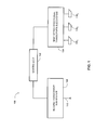
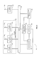
- System 350 includes a first band transceiving array 352, a second band transceiving antenna 354, a second-band transceiver module 356, a switch 358, a RADAR receiver 360, a communications receiver 362, a signal generator 364 and a controller 366.
- Transceiving array 352 includes a plurality of antennas 368 1 , 368 2 , ..., 368 N and corresponding first-band transceiver modules 370 1 , 370 2 , ..., 370 N .
- Each one of antennas 354, 368 1 , 368 2 , ..., 368 N may be embodied as a blade antenna.
- Signal source generator 364 is coupled with controller 366, with RADAR receiver 360, with communications receiver 362 and with switch 358.
- RADAR receiver 360 is further coupled with switch 358 and with controller 366.
- Communications receiver 362 is further coupled with switch 358 and with controller 366.
- Each one of first-band transceiver modules 370 1 , 370 2 , ..., 370 N is coupled with a corresponding one of antennas 368 1 , 368 2 , ..., 368 N and with switch 358.
- Second-band transceiver module 356 is coupled with second-band transceiving antenna 354 and with switch 358. Controller 366 is further coupled with switch 358.
- Controller 366 further manages the different missions of system 350 such as emitter signal acquisition (i.e., recognizing the transmission of an emitter and determining the characteristics thereof) and emitter maintenance (i.e., updating the characteristics of an acquired emitter).
- emitter signal acquisition i.e., recognizing the transmission of an emitter and determining the characteristics thereof
- emitter maintenance i.e., updating the characteristics of an acquired emitter
- transceiver modules 370 1 , 370 2 , ..., 370 N and 356 receives a source signal, transmitted by a source (i.e., an emitter), via the respective one of antennas 368 1 , 368 2 , ..., 368 N and 354.
- a source i.e., an emitter
- Each one of transceivers 370 1 , 370 2 , ..., 370 N and 356 performs down conversion, filtering sampling and the like.
- Each one of transceivers 370 1 , 370 2 , ..., 370 N and 356 provide the received signal thereof to RADAR receiver 360 and communications receiver 362.
- RADAR receiver 360 determines first and second received RADAR signal parameters corresponding to the first and second frequency band.
- RADAR receiver 360 and communications receiver 362 may alter the relative phase of the re-transmitted signal to introduce additional effects to the re-transmitted signal. Furthermore, RADAR receiver 360 and communications receiver 362 provide the determined received signals parameters to signal source generator 364.
- Signal source generator 364 generates a first intermediate signal according to the first received signal parameters and a second intermediate signal according to the second received signal parameters.
- signal source generator 364 provides the first intermediate signal to transceiver modules 370 1 , 370 2 , ..., 370 N .
- Each one of transceiver modules 370 1 , 370 2 , ..., 370 N shifts the phase of the first intermediate signal by the corresponding relative phase shift thereof, amplifies the corresponding phase shifted signal and re-transmits the amplified signal via the corresponding one of antennas 368 1 , 368 2 , ..., 368 N .
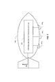
- the low frequencies tactical ECM system may be housed within an aerodynamic container attachable to an aircraft.
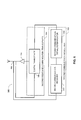
- Figure 7 is a schematic illustration of a low frequencies tactical ECM system generally reference 400, housed within an aerodynamic container 402, in accordance with a further embodiment of the disclosed technique.
- Low frequencies tactical ECM system 400 corresponds to low frequencies tactical ECM system, generally reference 100 of Figure 1 .
- Aerodynamic container 402 is attachable to an aircraft.
- the transceiver system includes antennas 404 1 , 404 2 , ..., 404 N and antenna 406.
- Antennas 404 1 , 404 2 , ..., 404 N are affixed on the exterior of aerodynamic container 402 and antenna 406 is located at one of the fins of aerodynamic container 402.
- low frequencies tactical ECM system generally reference 400 is may be used for self protection of air crafts or for escort jamming purposes.
- antennas 404 1 , 404 2 , ..., 404 N are 'blade antennas' (i.e., antennas that are located within a body exhibiting a blade like shape), thus, maintaining the aerodynamic structure of aerodynamic container 402.
- antennas 404 1 , 404 2 , ..., 404 N may also be located on the fins of aerodynamic container 402.
- antenna 406 may be affixed on the exterior of aerodynamic container 402 and be embodied as a blade antenna.
- Aerodynamic container 402 may be for example a pod, a munitions shell such as a bomb shell, a munitions contour (i.e., having the shape of a munitions shell by made of a different material), fuel tanks or cargo tanks.
- retro-directional transceiver system 400 may be any one of transceiver system 100 described in conjunction with Figure 1 .
- FIG 8 is a schematic illustration of a low frequencies tactical ECM system generally reference 420, housed within an aerodynamic container 422, in accordance with another embodiment of the disclosed technique.
- Low frequencies tactical ECM system 420 corresponds to low frequencies tactical ECM system, generally reference 100 of Figure 1 .
- Aerodynamic container 422 is attachable to an aircraft.
- the retro-directional transceiver system includes antennas 424 1 , 424 2 , ..., 424 N and antenna 426.
- Antennas 424 1 , 424 2 , ..., 424 N are located within aerodynamic container 422 and antenna 426 is located at the one of the fins if aerodynamic container 422.
- antenna 426 is located at the one of the fins if aerodynamic container 422.
- Aerodynamic container 422 may be for example a pod, a munitions shell such as a bomb shell, a munitions contour (i.e., having the shape of a munitions shell by made of a different material), fuel tanks or cargo tanks.
- a munitions shell such as a bomb shell
- a munitions contour i.e., having the shape of a munitions shell by made of a different material
- fuel tanks or cargo tanks may be for example a pod, a munitions shell such as a bomb shell, a munitions contour (i.e., having the shape of a munitions shell by made of a different material), fuel tanks or cargo tanks.
- tactical ECM system generally reference 400
- transceiver system 420 ( Figure 7 ) may be any one of transceiver system 100 described in conjunction with Figure 1 .
- each one of the antennas described hereinabove may be any type of antenna (e.g., a monopole antenna, a dipole antenna, a slot antenna, a loop antenna, a spiral antenna) exhibiting any desired shape thus achieving desired properties such as bandwidth and directionality.
- a monopole antenna e.g., a monopole antenna, a dipole antenna, a slot antenna, a loop antenna, a spiral antenna
- desired properties such as bandwidth and directionality.
Applications Claiming Priority (3)
| Application Number | Priority Date | Filing Date | Title |
|---|---|---|---|
| IL204908A IL204908A (en) | 2010-04-08 | 2010-04-08 | Electronic Response System |
| IL204909A IL204909A0 (en) | 2010-04-08 | 2010-04-08 | Retro - direction transceiver system |
| EP11721831.3A EP2556385B2 (fr) | 2010-04-08 | 2011-04-06 | Système de mesure de compteur électronique |
Related Parent Applications (3)
| Application Number | Title | Priority Date | Filing Date |
|---|---|---|---|
| EP11721831.3A Division EP2556385B2 (fr) | 2010-04-08 | 2011-04-06 | Système de mesure de compteur électronique |
| EP11721831.3A Division-Into EP2556385B2 (fr) | 2010-04-08 | 2011-04-06 | Système de mesure de compteur électronique |
| EP11721831.3 Division | 2011-04-06 |
Publications (3)
| Publication Number | Publication Date |
|---|---|
| EP2669700A2 true EP2669700A2 (fr) | 2013-12-04 |
| EP2669700A3 EP2669700A3 (fr) | 2014-03-19 |
| EP2669700B1 EP2669700B1 (fr) | 2016-08-31 |
Family
ID=44483830
Family Applications (2)
| Application Number | Title | Priority Date | Filing Date |
|---|---|---|---|
| EP13004209.6A Active EP2669700B1 (fr) | 2010-04-08 | 2011-04-06 | Système de contre-mesures électroniques |
| EP11721831.3A Active EP2556385B2 (fr) | 2010-04-08 | 2011-04-06 | Système de mesure de compteur électronique |
Family Applications After (1)
| Application Number | Title | Priority Date | Filing Date |
|---|---|---|---|
| EP11721831.3A Active EP2556385B2 (fr) | 2010-04-08 | 2011-04-06 | Système de mesure de compteur électronique |
Country Status (12)
| Country | Link |
|---|---|
| US (2) | US8203479B2 (fr) |
| EP (2) | EP2669700B1 (fr) |
| KR (1) | KR20130040832A (fr) |
| BR (1) | BR112012025506A2 (fr) |
| CL (1) | CL2012002818A1 (fr) |
| CO (1) | CO6630179A2 (fr) |
| DK (2) | DK2556385T3 (fr) |
| ES (2) | ES2461998T3 (fr) |
| PL (2) | PL2556385T3 (fr) |
| PT (2) | PT2669700T (fr) |
| SG (2) | SG178928A1 (fr) |
| WO (1) | WO2011125060A2 (fr) |
Families Citing this family (22)
| Publication number | Priority date | Publication date | Assignee | Title |
|---|---|---|---|---|
| BR112012025506A2 (pt) * | 2010-04-08 | 2016-06-21 | Elbit Systems Ew And Sigint Elisra Ltd | sistema de contramedida eletrônico |
| US8886038B1 (en) * | 2011-04-29 | 2014-11-11 | Bae Systems Information And Electronic Systems Integration Inc. | Weighted waveforms for improved jam code effectiveness |
| US9020343B1 (en) * | 2011-04-29 | 2015-04-28 | Bae Systems Information And Electronic Systems Integration Inc. | Pre-jam waveforms for enhanced optical break lock jamming effects |
| DE102011106507A1 (de) * | 2011-06-15 | 2012-12-20 | Astrium Gmbh | Vorrichtung zur Fahrzeug-ortung und -verfolgung |
| RU2486536C1 (ru) * | 2012-02-07 | 2013-06-27 | Виктор Владимирович Млечин | Способ создания двухчастотной помехи |
| US9564682B2 (en) * | 2012-07-11 | 2017-02-07 | Digimarc Corporation | Body-worn phased-array antenna |
| RU2545168C2 (ru) * | 2012-08-29 | 2015-03-27 | Федеральное государственное военное образовательное учреждение высшего профессионального образования "Военный авиационный инженерный университет" (г. Воронеж) Министерства обороны Российской Федерации | Многофункциональная станция помех |
| RU2577843C1 (ru) * | 2015-04-27 | 2016-03-20 | ОАО "Научно-технический центр радиоэлектронной борьбы" | Способ защиты мобильных объектов от радиолокационных средств разведки и наведения оружия |
| US9965267B2 (en) | 2015-11-19 | 2018-05-08 | Raytheon Company | Dynamic interface for firmware updates |
| US10473758B2 (en) * | 2016-04-06 | 2019-11-12 | Raytheon Company | Universal coherent technique generator |
| RU2622904C1 (ru) * | 2016-04-07 | 2017-06-21 | Закрытое акционерное общество "Научно-исследовательский институт современных телекоммуникационных технологий" | Способ искажения радиолокационного изображения в космической радиолокационной станции с синтезированной апертурой антенны |
| RU2609527C1 (ru) * | 2016-04-18 | 2017-02-02 | АО "Научно-технический центр радиоэлектронной борьбы" | Станция радиотехнической разведки |
| RU2672577C2 (ru) * | 2016-09-06 | 2018-11-16 | Федеральное государственное казенное военное образовательное учреждение высшего образования "Военный учебно-научный центр Военно-воздушных сил "Военно-воздушная академия имени профессора Н.Е. Жуковского и Ю.А. Гагарина" (г. Воронеж) Министерства обороны Российской Федерации | Способ идентификации уводящей помехи |
| RU2660469C1 (ru) * | 2017-11-03 | 2018-07-06 | Акционерное общество "Центральный научно-исследовательский радиотехнический институт имени академика А.И. Берга" (АО "ЦНИРТИ им. академика А.И. Берга") | Станция активных помех |
| RU2681202C1 (ru) * | 2018-05-29 | 2019-03-05 | Акционерное общество "НИИ измерительных приборов - Новосибирский завод имени Коминтерна" /АО "НПО НИИИП-НЗиК"/ | Способ определения дальности до постановщика прицельной по частоте шумовой помехи |
| RU2692077C1 (ru) * | 2018-05-29 | 2019-06-21 | Акционерное общество "Научно-технический центр радиоэлектронной борьбы" | Способ применения станций активных помех в составе зенитно-ракетных комплексов |
| RU2705561C1 (ru) * | 2019-04-01 | 2019-11-08 | Акционерное общество "Научно-исследовательский институт телевидения" | Способ оценки разведывательной защищенности линий радиосвязи передающего радиоцентра |
| CN110187332B (zh) * | 2019-05-15 | 2022-01-18 | 中科宇达(北京)科技有限公司 | 基于数字波束形成技术的低空防御雷达系统及方法 |
| RU2771138C1 (ru) * | 2020-12-29 | 2022-04-27 | Акционерное общество "Таганрогский научно-исследовательский институт связи" (АО "ТНИИС") | Корабельная станция радиотехнической разведки |
| US20220260675A1 (en) * | 2021-02-18 | 2022-08-18 | The United States Of America, As Represented By The Secretary Of The Navy | Ground based radar cross section measurement of countermeasures |
| WO2022195345A1 (fr) * | 2021-03-19 | 2022-09-22 | Станислав ЗАВЬЯЛОВ | Station d'interférences radio-électroniques actives "омут-civ" |
| IT202100007574A1 (it) * | 2021-03-26 | 2022-09-26 | Hi Te S R L | Apparecchiatura per la generazione di campi elettromagnetici di disturbo verso apparati elettronici |
Citations (3)
| Publication number | Priority date | Publication date | Assignee | Title |
|---|---|---|---|---|
| US4467328A (en) | 1981-10-26 | 1984-08-21 | Westinghouse Electric Corp. | Radar jammer with an antenna array of pseudo-randomly spaced radiating elements |
| US4472719A (en) | 1973-01-15 | 1984-09-18 | The United States Of America As Represented By The Secretary Of The Navy | ECM Multiple-target retrodirective antenna |
| US7248203B2 (en) | 2002-11-18 | 2007-07-24 | Lockheed Martin Corporation | System and method for detecting and jamming emitter signals |
Family Cites Families (21)
| Publication number | Priority date | Publication date | Assignee | Title |
|---|---|---|---|---|
| US3681771A (en) * | 1970-03-23 | 1972-08-01 | Macdowell Associates Inc | Retroflector dipole antenna array and method of making |
| US4001691A (en) * | 1975-01-30 | 1977-01-04 | Gruenberg Elliot | Communications relay system |
| US6297762B1 (en) * | 1979-06-27 | 2001-10-02 | Raytheon Company | Electronic countermeasures system |
| GB2286308A (en) * | 1994-02-07 | 1995-08-09 | Secr Defence | Radar jammer |
| US5623270A (en) * | 1994-10-12 | 1997-04-22 | Riverside Research Institute | Phased array antenna |
| US5781845A (en) * | 1996-12-03 | 1998-07-14 | The Aerospace Corporation | Adaptive transmitting antenna |
| JP3597678B2 (ja) * | 1997-08-18 | 2004-12-08 | 富士通株式会社 | レーダ装置 |
| JP3713922B2 (ja) | 1997-10-30 | 2005-11-09 | セイコーエプソン株式会社 | 液晶表示装置の駆動装置、液晶表示装置、電子機器、及び液晶表示装置の駆動方法 |
| US6252544B1 (en) * | 1998-01-27 | 2001-06-26 | Steven M. Hoffberg | Mobile communication device |
| KR100264817B1 (ko) * | 1998-06-09 | 2000-09-01 | 박태진 | 광대역 마이크로스트립 다이폴 안테나 어레이 |
| FR2848302B1 (fr) * | 2002-12-10 | 2005-05-27 | Thales Sa | Procede de calibration d'une source hyperfrequence |
| US7006039B2 (en) * | 2003-08-05 | 2006-02-28 | University Of Hawaii | Microwave self-phasing antenna arrays for secure data transmission & satellite network crosslinks |
| KR100783476B1 (ko) * | 2004-06-21 | 2007-12-07 | 후지쓰 텐 가부시키가이샤 | 레이더 장치 |
| US7821623B2 (en) * | 2004-11-16 | 2010-10-26 | The Boeing Company | Surveillance satellite image denial system |
| IL178910A (en) † | 2006-10-26 | 2008-04-13 | Rst Reut Systems & Advanced Te | Airborne bait that transmits radio frequencies (RF) and a method of deceiving radar-guided missiles by exploiting it |
| US8182103B1 (en) * | 2007-08-20 | 2012-05-22 | Raytheon Company | Modular MMW power source |
| US8254433B2 (en) * | 2008-01-08 | 2012-08-28 | Raytheon Company | Non-federated multi-function Ka-band exciter system and method |
| US8509205B2 (en) * | 2008-06-05 | 2013-08-13 | The Boeing Company | Multicode aperture transmitter/receiver |
| US8248320B2 (en) * | 2008-09-24 | 2012-08-21 | Raytheon Company | Lens array module |
| US20110224865A1 (en) * | 2010-03-11 | 2011-09-15 | Honeywell International Inc. | Health monitoring systems and methods with vehicle velocity |
| BR112012025506A2 (pt) * | 2010-04-08 | 2016-06-21 | Elbit Systems Ew And Sigint Elisra Ltd | sistema de contramedida eletrônico |
-
2011
- 2011-04-06 BR BR112012025506A patent/BR112012025506A2/pt not_active IP Right Cessation
- 2011-04-06 SG SG2012014387A patent/SG178928A1/en unknown
- 2011-04-06 ES ES11721831.3T patent/ES2461998T3/es active Active
- 2011-04-06 US US13/387,171 patent/US8203479B2/en active Active
- 2011-04-06 WO PCT/IL2011/000292 patent/WO2011125060A2/fr active Application Filing
- 2011-04-06 EP EP13004209.6A patent/EP2669700B1/fr active Active
- 2011-04-06 PL PL11721831T patent/PL2556385T3/pl unknown
- 2011-04-06 DK DK11721831.3T patent/DK2556385T3/da active
- 2011-04-06 ES ES13004209.6T patent/ES2600905T3/es active Active
- 2011-04-06 KR KR1020127027565A patent/KR20130040832A/ko not_active Application Discontinuation
- 2011-04-06 PT PT130042096T patent/PT2669700T/pt unknown
- 2011-04-06 PT PT117218313T patent/PT2556385E/pt unknown
- 2011-04-06 SG SG2013067863A patent/SG193870A1/en unknown
- 2011-04-06 EP EP11721831.3A patent/EP2556385B2/fr active Active
- 2011-04-06 PL PL13004209T patent/PL2669700T3/pl unknown
- 2011-04-06 DK DK13004209.6T patent/DK2669700T3/en active
-
2012
- 2012-05-11 US US13/469,611 patent/US8368580B2/en active Active
- 2012-10-08 CL CL2012002818A patent/CL2012002818A1/es unknown
- 2012-11-06 CO CO12199262A patent/CO6630179A2/es active IP Right Grant
Patent Citations (3)
| Publication number | Priority date | Publication date | Assignee | Title |
|---|---|---|---|---|
| US4472719A (en) | 1973-01-15 | 1984-09-18 | The United States Of America As Represented By The Secretary Of The Navy | ECM Multiple-target retrodirective antenna |
| US4467328A (en) | 1981-10-26 | 1984-08-21 | Westinghouse Electric Corp. | Radar jammer with an antenna array of pseudo-randomly spaced radiating elements |
| US7248203B2 (en) | 2002-11-18 | 2007-07-24 | Lockheed Martin Corporation | System and method for detecting and jamming emitter signals |
Also Published As
| Publication number | Publication date |
|---|---|
| ES2461998T3 (es) | 2014-05-22 |
| WO2011125060A2 (fr) | 2011-10-13 |
| US20120223851A1 (en) | 2012-09-06 |
| CL2012002818A1 (es) | 2014-06-06 |
| PL2556385T3 (pl) | 2014-11-28 |
| DK2556385T3 (da) | 2014-06-10 |
| CO6630179A2 (es) | 2013-03-01 |
| PT2556385E (pt) | 2014-05-15 |
| PT2669700T (pt) | 2016-12-20 |
| ES2600905T3 (es) | 2017-02-13 |
| BR112012025506A2 (pt) | 2016-06-21 |
| EP2669700A3 (fr) | 2014-03-19 |
| EP2556385A2 (fr) | 2013-02-13 |
| WO2011125060A3 (fr) | 2011-12-29 |
| EP2669700B1 (fr) | 2016-08-31 |
| KR20130040832A (ko) | 2013-04-24 |
| EP2556385B2 (fr) | 2017-06-14 |
| US8203479B2 (en) | 2012-06-19 |
| SG193870A1 (en) | 2013-10-30 |
| DK2669700T3 (en) | 2016-12-05 |
| SG178928A1 (en) | 2012-04-27 |
| EP2556385B1 (fr) | 2014-03-19 |
| US8368580B2 (en) | 2013-02-05 |
| PL2669700T3 (pl) | 2017-02-28 |
| US20120119933A1 (en) | 2012-05-17 |
Similar Documents
| Publication | Publication Date | Title |
|---|---|---|
| EP2669700B1 (fr) | Système de contre-mesures électroniques | |
| US7994969B2 (en) | OFDM frequency scanning radar | |
| EP2131508B1 (fr) | Transmetteur/récepteur d'ouverture multicodes | |
| Wang et al. | First demonstration of joint wireless communication and high-resolution SAR imaging using airborne MIMO radar system | |
| EP2251705B1 (fr) | Système et procédé d'utilisation d'un système radar en mode onde continue pour la communication de données | |
| US9885777B2 (en) | Detection of stealth vehicles using VHF radar | |
| CN105866746A (zh) | 一种数字相控阵中fmcw体制t/r单元的应用 | |
| Cui et al. | Dual-use unimodular sequence design via frequency nulling modulation | |
| CN106970388A (zh) | 双星Ka FMCW PANEL SAR成像系统 | |
| Heino et al. | On the prospects of in-band full-duplex radios as monostatic continuous-wave noise radars | |
| US10630322B2 (en) | High power signal communications within a power limit | |
| US9170321B2 (en) | Method and radar system for repetition jammer and clutter supression | |
| Wang et al. | Joint wireless communication and high resolution SAR imaging using airborne MIMO radar system | |
| US20060255999A1 (en) | Radar system having a beamless emission signature | |
| CN112014808A (zh) | 一种弹载双基sar抗干扰系统及其工作方法 | |
| IL204908A (en) | Electronic Response System | |
| CN111077502A (zh) | 多频段虚拟的扩展阵列系统 | |
| Grossi et al. | Spectrum-sharing between a surveillance radar and a mimo communication system in cluttered environments | |
| Zhang et al. | Synthesis of directional modulation LFM radar waveform for sidelobe jamming suppression | |
| du Preez et al. | Systems Aspects of Millimeter-Wave Power Amplifiers | |
| Skolnik | Status of ultrawideband (UWB) radar and its technology | |
| Kellett et al. | Multifunction Maritime Radar and RF Systems—Technology Challenges and Areas of Development | |
| Li et al. | Spaceborne phased array antenna for communication systems | |
| Mishra et al. | Millimeter-Wave and THz-Band Joint Radar-Communications | |
| Scotti et al. | Photonics Enabling Coherent MIMO Radar Networks |
Legal Events
| Date | Code | Title | Description |
|---|---|---|---|
| PUAI | Public reference made under article 153(3) epc to a published international application that has entered the european phase |
Free format text: ORIGINAL CODE: 0009012 |
|
| 17P | Request for examination filed |
Effective date: 20130917 |
|
| AC | Divisional application: reference to earlier application |
Ref document number: 2556385 Country of ref document: EP Kind code of ref document: P |
|
| AK | Designated contracting states |
Kind code of ref document: A2 Designated state(s): AL AT BE BG CH CY CZ DE DK EE ES FI FR GB GR HR HU IE IS IT LI LT LU LV MC MK MT NL NO PL PT RO RS SE SI SK SM TR |
|
| RIN1 | Information on inventor provided before grant (corrected) |
Inventor name: RAYBEE, ARYE Inventor name: KANTER, ERAN Inventor name: MANELA, REUEL Inventor name: BLANK, DAVID |
|
| PUAL | Search report despatched |
Free format text: ORIGINAL CODE: 0009013 |
|
| AK | Designated contracting states |
Kind code of ref document: A3 Designated state(s): AL AT BE BG CH CY CZ DE DK EE ES FI FR GB GR HR HU IE IS IT LI LT LU LV MC MK MT NL NO PL PT RO RS SE SI SK SM TR |
|
| RIC1 | Information provided on ipc code assigned before grant |
Ipc: G01S 7/38 20060101AFI20140210BHEP |
|
| 17Q | First examination report despatched |
Effective date: 20150408 |
|
| 17Q | First examination report despatched |
Effective date: 20150420 |
|
| GRAP | Despatch of communication of intention to grant a patent |
Free format text: ORIGINAL CODE: EPIDOSNIGR1 |
|
| INTG | Intention to grant announced |
Effective date: 20160311 |
|
| RAP1 | Party data changed (applicant data changed or rights of an application transferred) |
Owner name: ELBIT SYSTEMS EW AND SIGINT - ELISRA LTD. |
|
| GRAS | Grant fee paid |
Free format text: ORIGINAL CODE: EPIDOSNIGR3 |
|
| GRAA | (expected) grant |
Free format text: ORIGINAL CODE: 0009210 |
|
| AC | Divisional application: reference to earlier application |
Ref document number: 2556385 Country of ref document: EP Kind code of ref document: P |
|
| AK | Designated contracting states |
Kind code of ref document: B1 Designated state(s): AL AT BE BG CH CY CZ DE DK EE ES FI FR GB GR HR HU IE IS IT LI LT LU LV MC MK MT NL NO PL PT RO RS SE SI SK SM TR |
|
| REG | Reference to a national code |
Ref country code: CH Ref legal event code: EP Ref country code: GB Ref legal event code: FG4D |
|
| REG | Reference to a national code |
Ref country code: IE Ref legal event code: FG4D |
|
| REG | Reference to a national code |
Ref country code: AT Ref legal event code: REF Ref document number: 825445 Country of ref document: AT Kind code of ref document: T Effective date: 20161015 |
|
| REG | Reference to a national code |
Ref country code: DE Ref legal event code: R096 Ref document number: 602011029990 Country of ref document: DE |
|
| REG | Reference to a national code |
Ref country code: NL Ref legal event code: FP |
|
| REG | Reference to a national code |
Ref country code: SE Ref legal event code: TRGR |
|
| REG | Reference to a national code |
Ref country code: DK Ref legal event code: T3 Effective date: 20161128 |
|
| REG | Reference to a national code |
Ref country code: NO Ref legal event code: T2 Effective date: 20160831 |
|
| REG | Reference to a national code |
Ref country code: PT Ref legal event code: SC4A Ref document number: 2669700 Country of ref document: PT Date of ref document: 20161220 Kind code of ref document: T Free format text: AVAILABILITY OF NATIONAL TRANSLATION Effective date: 20161130 |
|
| REG | Reference to a national code |
Ref country code: LT Ref legal event code: MG4D |
|
| REG | Reference to a national code |
Ref country code: AT Ref legal event code: MK05 Ref document number: 825445 Country of ref document: AT Kind code of ref document: T Effective date: 20160831 |
|
| PG25 | Lapsed in a contracting state [announced via postgrant information from national office to epo] |
Ref country code: LT Free format text: LAPSE BECAUSE OF FAILURE TO SUBMIT A TRANSLATION OF THE DESCRIPTION OR TO PAY THE FEE WITHIN THE PRESCRIBED TIME-LIMIT Effective date: 20160831 Ref country code: RS Free format text: LAPSE BECAUSE OF FAILURE TO SUBMIT A TRANSLATION OF THE DESCRIPTION OR TO PAY THE FEE WITHIN THE PRESCRIBED TIME-LIMIT Effective date: 20160831 Ref country code: HR Free format text: LAPSE BECAUSE OF FAILURE TO SUBMIT A TRANSLATION OF THE DESCRIPTION OR TO PAY THE FEE WITHIN THE PRESCRIBED TIME-LIMIT Effective date: 20160831 |
|
| REG | Reference to a national code |
Ref country code: ES Ref legal event code: FG2A Ref document number: 2600905 Country of ref document: ES Kind code of ref document: T3 Effective date: 20170213 |
|
| PG25 | Lapsed in a contracting state [announced via postgrant information from national office to epo] |
Ref country code: LV Free format text: LAPSE BECAUSE OF FAILURE TO SUBMIT A TRANSLATION OF THE DESCRIPTION OR TO PAY THE FEE WITHIN THE PRESCRIBED TIME-LIMIT Effective date: 20160831 Ref country code: AT Free format text: LAPSE BECAUSE OF FAILURE TO SUBMIT A TRANSLATION OF THE DESCRIPTION OR TO PAY THE FEE WITHIN THE PRESCRIBED TIME-LIMIT Effective date: 20160831 |
|
| REG | Reference to a national code |
Ref country code: GR Ref legal event code: EP Ref document number: 20160402646 Country of ref document: GR Effective date: 20170130 |
|
| REG | Reference to a national code |
Ref country code: FR Ref legal event code: PLFP Year of fee payment: 7 |
|
| PG25 | Lapsed in a contracting state [announced via postgrant information from national office to epo] |
Ref country code: RO Free format text: LAPSE BECAUSE OF FAILURE TO SUBMIT A TRANSLATION OF THE DESCRIPTION OR TO PAY THE FEE WITHIN THE PRESCRIBED TIME-LIMIT Effective date: 20160831 Ref country code: EE Free format text: LAPSE BECAUSE OF FAILURE TO SUBMIT A TRANSLATION OF THE DESCRIPTION OR TO PAY THE FEE WITHIN THE PRESCRIBED TIME-LIMIT Effective date: 20160831 |
|
| PG25 | Lapsed in a contracting state [announced via postgrant information from national office to epo] |
Ref country code: BG Free format text: LAPSE BECAUSE OF FAILURE TO SUBMIT A TRANSLATION OF THE DESCRIPTION OR TO PAY THE FEE WITHIN THE PRESCRIBED TIME-LIMIT Effective date: 20161130 Ref country code: CZ Free format text: LAPSE BECAUSE OF FAILURE TO SUBMIT A TRANSLATION OF THE DESCRIPTION OR TO PAY THE FEE WITHIN THE PRESCRIBED TIME-LIMIT Effective date: 20160831 Ref country code: SM Free format text: LAPSE BECAUSE OF FAILURE TO SUBMIT A TRANSLATION OF THE DESCRIPTION OR TO PAY THE FEE WITHIN THE PRESCRIBED TIME-LIMIT Effective date: 20160831 Ref country code: SK Free format text: LAPSE BECAUSE OF FAILURE TO SUBMIT A TRANSLATION OF THE DESCRIPTION OR TO PAY THE FEE WITHIN THE PRESCRIBED TIME-LIMIT Effective date: 20160831 |
|
| PGFP | Annual fee paid to national office [announced via postgrant information from national office to epo] |
Ref country code: PT Payment date: 20170327 Year of fee payment: 7 |
|
| REG | Reference to a national code |
Ref country code: DE Ref legal event code: R097 Ref document number: 602011029990 Country of ref document: DE |
|
| PLBE | No opposition filed within time limit |
Free format text: ORIGINAL CODE: 0009261 |
|
| STAA | Information on the status of an ep patent application or granted ep patent |
Free format text: STATUS: NO OPPOSITION FILED WITHIN TIME LIMIT |
|
| PGFP | Annual fee paid to national office [announced via postgrant information from national office to epo] |
Ref country code: NO Payment date: 20170421 Year of fee payment: 7 Ref country code: DK Payment date: 20170424 Year of fee payment: 7 |
|
| 26N | No opposition filed |
Effective date: 20170601 |
|
| PG25 | Lapsed in a contracting state [announced via postgrant information from national office to epo] |
Ref country code: SI Free format text: LAPSE BECAUSE OF FAILURE TO SUBMIT A TRANSLATION OF THE DESCRIPTION OR TO PAY THE FEE WITHIN THE PRESCRIBED TIME-LIMIT Effective date: 20160831 |
|
| PGFP | Annual fee paid to national office [announced via postgrant information from national office to epo] |
Ref country code: BE Payment date: 20170424 Year of fee payment: 7 Ref country code: ES Payment date: 20170503 Year of fee payment: 7 |
|
| REG | Reference to a national code |
Ref country code: CH Ref legal event code: PL |
|
| REG | Reference to a national code |
Ref country code: IE Ref legal event code: MM4A |
|
| PG25 | Lapsed in a contracting state [announced via postgrant information from national office to epo] |
Ref country code: MC Free format text: LAPSE BECAUSE OF FAILURE TO SUBMIT A TRANSLATION OF THE DESCRIPTION OR TO PAY THE FEE WITHIN THE PRESCRIBED TIME-LIMIT Effective date: 20160831 |
|
| PG25 | Lapsed in a contracting state [announced via postgrant information from national office to epo] |
Ref country code: LI Free format text: LAPSE BECAUSE OF NON-PAYMENT OF DUE FEES Effective date: 20170430 Ref country code: LU Free format text: LAPSE BECAUSE OF NON-PAYMENT OF DUE FEES Effective date: 20170406 Ref country code: CH Free format text: LAPSE BECAUSE OF NON-PAYMENT OF DUE FEES Effective date: 20170430 |
|
| REG | Reference to a national code |
Ref country code: FR Ref legal event code: PLFP Year of fee payment: 8 |
|
| PG25 | Lapsed in a contracting state [announced via postgrant information from national office to epo] |
Ref country code: IE Free format text: LAPSE BECAUSE OF NON-PAYMENT OF DUE FEES Effective date: 20170406 |
|
| PG25 | Lapsed in a contracting state [announced via postgrant information from national office to epo] |
Ref country code: MT Free format text: LAPSE BECAUSE OF NON-PAYMENT OF DUE FEES Effective date: 20170406 |
|
| PG25 | Lapsed in a contracting state [announced via postgrant information from national office to epo] |
Ref country code: AL Free format text: LAPSE BECAUSE OF FAILURE TO SUBMIT A TRANSLATION OF THE DESCRIPTION OR TO PAY THE FEE WITHIN THE PRESCRIBED TIME-LIMIT Effective date: 20160831 |
|
| REG | Reference to a national code |
Ref country code: DK Ref legal event code: EBP Effective date: 20180430 Ref country code: NO Ref legal event code: MMEP |
|
| REG | Reference to a national code |
Ref country code: BE Ref legal event code: FP Effective date: 20161129 Ref country code: BE Ref legal event code: MM Effective date: 20180430 |
|
| PG25 | Lapsed in a contracting state [announced via postgrant information from national office to epo] |
Ref country code: NO Free format text: LAPSE BECAUSE OF NON-PAYMENT OF DUE FEES Effective date: 20180430 Ref country code: GR Free format text: LAPSE BECAUSE OF NON-PAYMENT OF DUE FEES Effective date: 20181106 Ref country code: PT Free format text: LAPSE BECAUSE OF NON-PAYMENT OF DUE FEES Effective date: 20181008 |
|
| PG25 | Lapsed in a contracting state [announced via postgrant information from national office to epo] |
Ref country code: BE Free format text: LAPSE BECAUSE OF NON-PAYMENT OF DUE FEES Effective date: 20180430 |
|
| PG25 | Lapsed in a contracting state [announced via postgrant information from national office to epo] |
Ref country code: DK Free format text: LAPSE BECAUSE OF NON-PAYMENT OF DUE FEES Effective date: 20180430 |
|
| PG25 | Lapsed in a contracting state [announced via postgrant information from national office to epo] |
Ref country code: HU Free format text: LAPSE BECAUSE OF FAILURE TO SUBMIT A TRANSLATION OF THE DESCRIPTION OR TO PAY THE FEE WITHIN THE PRESCRIBED TIME-LIMIT; INVALID AB INITIO Effective date: 20110406 |
|
| REG | Reference to a national code |
Ref country code: ES Ref legal event code: FD2A Effective date: 20190911 |
|
| PG25 | Lapsed in a contracting state [announced via postgrant information from national office to epo] |
Ref country code: ES Free format text: LAPSE BECAUSE OF NON-PAYMENT OF DUE FEES Effective date: 20180407 Ref country code: CY Free format text: LAPSE BECAUSE OF NON-PAYMENT OF DUE FEES Effective date: 20160831 |
|
| PG25 | Lapsed in a contracting state [announced via postgrant information from national office to epo] |
Ref country code: MK Free format text: LAPSE BECAUSE OF FAILURE TO SUBMIT A TRANSLATION OF THE DESCRIPTION OR TO PAY THE FEE WITHIN THE PRESCRIBED TIME-LIMIT Effective date: 20160831 |
|
| PG25 | Lapsed in a contracting state [announced via postgrant information from national office to epo] |
Ref country code: TR Free format text: LAPSE BECAUSE OF FAILURE TO SUBMIT A TRANSLATION OF THE DESCRIPTION OR TO PAY THE FEE WITHIN THE PRESCRIBED TIME-LIMIT Effective date: 20160831 |
|
| PG25 | Lapsed in a contracting state [announced via postgrant information from national office to epo] |
Ref country code: IS Free format text: LAPSE BECAUSE OF FAILURE TO SUBMIT A TRANSLATION OF THE DESCRIPTION OR TO PAY THE FEE WITHIN THE PRESCRIBED TIME-LIMIT Effective date: 20161231 |
|
| PGFP | Annual fee paid to national office [announced via postgrant information from national office to epo] |
Ref country code: FR Payment date: 20230309 Year of fee payment: 13 |
|
| PGFP | Annual fee paid to national office [announced via postgrant information from national office to epo] |
Ref country code: SE Payment date: 20230310 Year of fee payment: 13 Ref country code: PL Payment date: 20230314 Year of fee payment: 13 Ref country code: IT Payment date: 20230310 Year of fee payment: 13 Ref country code: GB Payment date: 20230302 Year of fee payment: 13 |
|
| PGFP | Annual fee paid to national office [announced via postgrant information from national office to epo] |
Ref country code: NL Payment date: 20230314 Year of fee payment: 13 |
|
| PGFP | Annual fee paid to national office [announced via postgrant information from national office to epo] |
Ref country code: DE Payment date: 20230307 Year of fee payment: 13 |
|
| PGFP | Annual fee paid to national office [announced via postgrant information from national office to epo] |
Ref country code: FI Payment date: 20230411 Year of fee payment: 13 |