EP2669555A1 - Leaf seal - Google Patents
Leaf seal Download PDFInfo
- Publication number
- EP2669555A1 EP2669555A1 EP13169762.5A EP13169762A EP2669555A1 EP 2669555 A1 EP2669555 A1 EP 2669555A1 EP 13169762 A EP13169762 A EP 13169762A EP 2669555 A1 EP2669555 A1 EP 2669555A1
- Authority
- EP
- European Patent Office
- Prior art keywords
- leaf
- abutment
- leaves
- seal
- pack
- Prior art date
- Legal status (The legal status is an assumption and is not a legal conclusion. Google has not performed a legal analysis and makes no representation as to the accuracy of the status listed.)
- Withdrawn
Links
- 230000015572 biosynthetic process Effects 0.000 claims abstract description 55
- 238000005755 formation reaction Methods 0.000 claims abstract description 55
- 238000000034 method Methods 0.000 claims description 2
- 238000011144 upstream manufacturing Methods 0.000 claims 1
- 238000002485 combustion reaction Methods 0.000 description 3
- 230000000694 effects Effects 0.000 description 3
- 230000001141 propulsive effect Effects 0.000 description 3
- 238000007789 sealing Methods 0.000 description 3
- 125000006850 spacer group Chemical group 0.000 description 3
- 230000006835 compression Effects 0.000 description 1
- 238000007906 compression Methods 0.000 description 1
- 239000000446 fuel Substances 0.000 description 1
- 239000000203 mixture Substances 0.000 description 1
- 238000012986 modification Methods 0.000 description 1
- 230000004048 modification Effects 0.000 description 1
Images




Classifications
-
- F—MECHANICAL ENGINEERING; LIGHTING; HEATING; WEAPONS; BLASTING
- F16—ENGINEERING ELEMENTS AND UNITS; GENERAL MEASURES FOR PRODUCING AND MAINTAINING EFFECTIVE FUNCTIONING OF MACHINES OR INSTALLATIONS; THERMAL INSULATION IN GENERAL
- F16J—PISTONS; CYLINDERS; SEALINGS
- F16J15/00—Sealings
- F16J15/16—Sealings between relatively-moving surfaces
- F16J15/32—Sealings between relatively-moving surfaces with elastic sealings, e.g. O-rings
- F16J15/3284—Sealings between relatively-moving surfaces with elastic sealings, e.g. O-rings characterised by their structure; Selection of materials
- F16J15/3292—Lamellar structures
-
- F—MECHANICAL ENGINEERING; LIGHTING; HEATING; WEAPONS; BLASTING
- F01—MACHINES OR ENGINES IN GENERAL; ENGINE PLANTS IN GENERAL; STEAM ENGINES
- F01D—NON-POSITIVE DISPLACEMENT MACHINES OR ENGINES, e.g. STEAM TURBINES
- F01D11/00—Preventing or minimising internal leakage of working-fluid, e.g. between stages
- F01D11/001—Preventing or minimising internal leakage of working-fluid, e.g. between stages for sealing space between stator blade and rotor
-
- F—MECHANICAL ENGINEERING; LIGHTING; HEATING; WEAPONS; BLASTING
- F01—MACHINES OR ENGINES IN GENERAL; ENGINE PLANTS IN GENERAL; STEAM ENGINES
- F01D—NON-POSITIVE DISPLACEMENT MACHINES OR ENGINES, e.g. STEAM TURBINES
- F01D11/00—Preventing or minimising internal leakage of working-fluid, e.g. between stages
- F01D11/02—Preventing or minimising internal leakage of working-fluid, e.g. between stages by non-contact sealings, e.g. of labyrinth type
-
- F—MECHANICAL ENGINEERING; LIGHTING; HEATING; WEAPONS; BLASTING
- F05—INDEXING SCHEMES RELATING TO ENGINES OR PUMPS IN VARIOUS SUBCLASSES OF CLASSES F01-F04
- F05D—INDEXING SCHEME FOR ASPECTS RELATING TO NON-POSITIVE-DISPLACEMENT MACHINES OR ENGINES, GAS-TURBINES OR JET-PROPULSION PLANTS
- F05D2240/00—Components
- F05D2240/55—Seals
- F05D2240/57—Leaf seals
-
- F—MECHANICAL ENGINEERING; LIGHTING; HEATING; WEAPONS; BLASTING
- F05—INDEXING SCHEMES RELATING TO ENGINES OR PUMPS IN VARIOUS SUBCLASSES OF CLASSES F01-F04
- F05D—INDEXING SCHEME FOR ASPECTS RELATING TO NON-POSITIVE-DISPLACEMENT MACHINES OR ENGINES, GAS-TURBINES OR JET-PROPULSION PLANTS
- F05D2240/00—Components
- F05D2240/55—Seals
- F05D2240/59—Lamellar seals
-
- F—MECHANICAL ENGINEERING; LIGHTING; HEATING; WEAPONS; BLASTING
- F16—ENGINEERING ELEMENTS AND UNITS; GENERAL MEASURES FOR PRODUCING AND MAINTAINING EFFECTIVE FUNCTIONING OF MACHINES OR INSTALLATIONS; THERMAL INSULATION IN GENERAL
- F16J—PISTONS; CYLINDERS; SEALINGS
- F16J15/00—Sealings
- F16J15/16—Sealings between relatively-moving surfaces
- F16J15/32—Sealings between relatively-moving surfaces with elastic sealings, e.g. O-rings
- F16J15/3284—Sealings between relatively-moving surfaces with elastic sealings, e.g. O-rings characterised by their structure; Selection of materials
- F16J15/3288—Filamentary structures, e.g. brush seals
Definitions
- the present invention relates to a leaf seal.
- Leaf seals may be used to form a seal between two relatively rotating components in order to maintain a relatively high pressure on one side of the seal and a relatively low pressure on the other.
- a leaf seal is arranged with a large number of typically rectangular leaves which are held at a defined angle to the radial all the way round the seal circumference. The leaves give the seal a low stiffness, and are packed together such that the total leakage through the seal is reduced. Nonetheless, interleaf gaps do provide the seal with a porous aerodynamic working section.
- Such seals may be used, for example, in gas turbine engines.
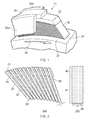
- Figure 1 shows schematically a cut-away perspective view of a portion of a leaf seal 31 comprising a pack of leaves 32.
- Figure 2 shows (a) a view along the axial direction of an arc segment of the pack to better show some of the leaves 32 edge-on, and (b) a plan view of a single leaf 32.
- the leaves 32 each have a root portion 40 and a working portion 41, and have a width w in the axial direction and a thickness t.
- the leaves alternate with spacer elements 33 at their root portions 40, and are secured thereat to a backing ring 34 of a housing, which typically also comprises front 35a (high pressure side) and rear (low pressure side) 35b rigid coverplates.
- the working portions 41 of the leaves 32 present end edges 36 towards a surface 37 of a rotating component (shaft) generally rotating in the direction depicted by arrowhead 38.
- the leaves 32, and in particular the end edges 36 of the leaves 32 act against the surface 37 in order to create a seal across the assembly 31.
- Each leaf 32 is sufficiently compliant in order to adjust with rotation of the surface 37, so that a good sealing effect is created.
- the spacers 33 ensure that flexibility is available to appropriately present the leaves 32 towards the surface 37 which, as illustrated, is generally with an inclined angle between them.
- the spacers 33 also help to form interleaf gaps 39 between adjacent working portions 41 of the leaves 32. A leakage flow through these gaps 39 is induced by the pressure differential across the seal.
- An aim of the present invention is to provide a leaf seal with a longer useful life.
- the present invention provides a leaf seal for effecting a seal between two, coaxial, relatively rotating components, the leaf seal having an annular pack of stacked leaves, the pack being mountable to a first one of the components at root portions of the leaves and extending towards the other component such that end edges of the leaves are presented for wiping contact with the other component and, in use, a pressure drop is maintained axially across the pack and the leaves are arranged to undergo a predetermined amount of blow-down during normal steady state operating conditions::
- a physical end stop can be created by the abutment formation of the leaf in combination with the stop portion of the coverplate.
- This physical end stop can act as a blow-down limiter, preventing excessive blow-down loading being applied on to the other component. This can reduce the amount of wear of the end edges and the other component, prolonging the usable lifetime of the seal.
- the present invention provides a gas turbine engine, such as an aero gas turbine engine, having one or more leaf seals according to the first aspect.
- the present invention provides use of the leaf seal of the first aspect to prevent excessive blow-down loading being applied on to the other component.
- a method of effecting a seal between two, coaxial, relatively rotating components can include: mounting the leaf seal of the first aspect to the two components; and rotating the components and maintaining a pressure drop axially across the pack of stacked leaves, the rotational speed and pressure drop producing blow-down causing the leaves to deflect radially by the predetermined amount, whereby the abutment formations abut the stop portion to prevent further radial deflection beyond that amount.
- Each abutment formation can be arranged to abut the stop portion during normal operation of the seal, e.g. during rotational transients. For example, as blow-down generally increases with increasing axial pressure drop, the predetermined amount of radial deflection can be reached at the highest axial pressure drop experienced during normal operation.
- the amount of radial deflection that can be tolerated in a seal scales with seal radius. For example, if R is the radius of the seal in metres at the end edge of the leaf, the predetermined amount of radial deflection in mm of the leaf measured at the end edge may be at least 0.4R, 0.7R or R. The predetermined amount of radial deflection in mm of the leaf measured at the end edge of the leaf may be at most 5R, 6R or 7R.
- Each leaf may have a respective abutment formation.
- the abutment formation and stop portion can be located at the high pressure side of the respective leaf or the low pressure side of the leaf. Even if only one coverplate provides the stop portion, the seal may nonetheless have coverplates at both sides of the pack. However, when the seal does have coverplates at both sides, another option is for an abutment formation and corresponding stop portion to be located at both sides of the respective leaf.
- the abutment formation can be located at a side edge of the respective leaf between its root portion and its end edge.
- the abutment formation may be provided by a step in the side edge of the leaf.
- the step may form a leaf which is wider at the root portion than at the end edge.
- Another option is for the abutment formation to be provided by a salient or outward projection from the side edge. The leaf can then be the same width at the root portion as at the end edge.
- the abutment formation may have an abutment surface that is substantially parallel to the axial direction.
- the abutment formation may have an abutment surface that is inclined to the axial direction.
- the abutment formation may have an abutment surface which is curved.
- the stop portion may have a surface that is substantially parallel to the axial direction for contact with the abutment surface of the leaf.
- the stop portion may have a surface that is inclined to the axial direction for contact with the abutment surface of the leaf.
- the stop portion may have a curved surface for contact with the abutment surface of the leaf.
- each leaf having an abutment formation may taper inwards from the root portion to the end edge.
- the clearance radially outwards of the abutment formations may be greater than the clearance between the abutment formations and stop portions in normal use.
- the leaf seal can be used, for example, in gas and steam turbines, and jet engines. However, it may also be used in other applications, e.g. where sealing between a high and low pressure region is required along a shaft.
- a ducted fan gas turbine engine incorporating the invention is generally indicated at 10 and has a principal and rotational axis X-X.
- the engine comprises, in axial flow series, an air intake 11, a propulsive fan 12, an intermediate pressure compressor 13, a high-pressure compressor 14, combustion equipment 15, a high-pressure turbine 16, and intermediate pressure turbine 17, a low-pressure turbine 18 and a core engine exhaust nozzle 19.
- a nacelle 21 generally surrounds the engine 10 and defines the intake 11, a bypass duct 22 and a bypass exhaust nozzle 23.
- air entering the intake 11 is accelerated by the fan 12 to produce two air flows: a first air flow A into the intermediate pressure compressor 13 and a second air flow B which passes through the bypass duct 22 to provide propulsive thrust.
- the intermediate pressure compressor 13 compresses the air flow A directed into it before delivering that air to the high pressure compressor 14 where further compression takes place.
- the compressed air exhausted from the high-pressure compressor 14 is directed into the combustion equipment 15 where it is mixed with fuel and the mixture combusted.
- the resultant hot combustion products then expand through, and thereby drive the high, intermediate and low-pressure turbines 16, 17, 18 before being exhausted through the nozzle 19 to provide additional propulsive thrust.
- the high, intermediate and low-pressure turbines respectively drive the high and intermediate pressure compressors 14, 13 and the fan 12 by suitable interconnecting shafts.
- the engine may have one or more leaf seals installed, for example, between an interconnecting shaft and a casing for the shaft.
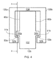
- Figure 4 shows a cross section of a leaf 132 and housing 134 of such a leaf seal.
- the leaf seal of Figure 4 has a circumferential pack of approximately rectangular leaves 132 extending to end edges 136 which make wiping contact with a rotor (e.g. an engine interconnecting shaft).
- the leaves are held at an inclined angle to the radial. Interleaf gaps are formed between the leaves 132, giving a porous aerodynamic working section and sufficient compliance to adjust to the rotor. Nonetheless, the leaves are packed sufficiently tightly together so that the total leakage through the seal is low.
- the housing 134 includes a front (high pressure) coverplate 135a and a rear (low pressure) coverplate 135b which each cover a portion of the radial extent of the leaf pack.
- the front coverplate 135a includes a stop portion 52a with a stop surface 53a.
- the rear coverplate 135b includes a stop portion 52b with a stop surface 53b.
- the leaf 132 has a front (high pressure) side edge 60a and a rear (low pressure) side edge 60b. These edges respectively include front 50a and rear 50b abutment formations in the form of outwardly projecting salients that cause the leaf to depart from a purely rectangular shape.
- Each abutment formation and its corresponding stop portion can therefore act as a physical blow-down limiter.
- the radial clearance between the abutment formations 50a, 50b and the stop portions 52a, 52b in a non-working state is less than the expected deflection during normal use.
- Leaf seals can be designed to undergo a predetermined amount of blow-down during normal steady state operating conditions. Blow-down deflection is proportional to blow-down force acting on the leaf which is proportional to the differential pressure. In the majority of applications there is a range of expected operating conditions for the seal which constitute normal operation. Hence, there will be at least a first operating pressure which induces a first level of blow-down force on the leaves, and a second, higher pressure operating point which induces a greater level of blow-down force.
- a leaf seal will be designed such that the blow-down force is sufficient to substantially close the gap between the edge end 136 of the leaves 132 and the rotor at the lower pressure operating point.
- the blow-down is proportional to the differential pressure, this means that the blow-down force will be too great at the second, higher pressure operating point. This will result in unnecessarily high rotor torque and wear.
- the present invention provides a blow-down limiter in the form of the stop portions 52a,b and abutment formations 50a,b to ensure that at higher pressure condition the leaf deflection is limited after a predetermined amount of pressure differential. As there is no sliding contact between the leaves and the coverplates any further pressure can be better absorbed without excessive and unnecessary wear to the rotor or leaf edge end 136.
- the abutment formations 50a,b may also be viewed as a means for reducing the effective free length of leaves 132 at pressures greater than a first predetermined pressure. This limits the amount of radial deflection which can be achieved in comparison to an unrestricted length. Additional blow-down can still be achieved above the first operating point but is limited to the free end beyond the abutment formations 50a,b. Thus the sealing force can be increased at higher pressures if necessary but in a more controlled way.
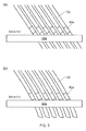
- Figure 5 shows schematically (a) a view of plane A-A of the leaf seal of Figure 4 , and (b) the view of plane A-A with a pressure load acting on the leaves.
- the pressure load causes blow-down deflection of the leaves 132, the deflection being prevented from causing excessive radial deflection by the abutment formations 50a coming into contact with the stop portion 52a.
- FIG. 6 illustrates the effect of different pressures on blow-down on a view of plane A-A of the leaf seal of Figure 4 . More particularly, individual leaves are shown for a range of different pressures ranging from the zero pressure case for the leaf on the far left (corresponding to Figure 5(a) ), to the high pressure case for the leaf on the far right (corresponding to Figure 5(b) ). As the pressure increases, the amount of blow-down increases and deflects the leaves radially inwardly. When the abutment formations 50a, 50b of a respective leaf 132 contact their corresponding stop portions 52a, 52b, further deflection is physically limited.
- any additional load acts upon the stop portions.
- the ability to limit deflection therefore leads to a maximum value of the load which can be exerted on the rotor, thereby reducing the amount of wear of the rotor and of the leaf end edges 136.
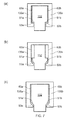
- Figures 7(a) to (c) show possible shapes of leaves 132 and coverplates 135a, 135b.
- Each leaf 132 has an abutment surface 51a on the abutment formation of the front side edge that contacts a stop surface 53a on the stop portion of the front coverplate 135a when the leaf is deflected radially by the predetermined amount.
- each leaf has an abutment surface 51b on the abutment formation of the rear side edge that contacts a stop surface 53b on the stop portion of the rear coverplate 135b when the leaf is deflected radially by the predetermined amount.
- each of the abutment formations of the front side edge and the rear side edges are a step in the respective side edge. These steps form abutment surfaces 51a and 51b which lie substantially parallel to the axial direction. Corresponding stop surfaces 53a and 53b also lie substantially parallel to the axial direction.
- the side edges 60a, 60b include abutment formations 50a, 50b in the form of outwardly projecting salients.
- the abutment surfaces 51a, 51b of the abutment formations are inclined to the axial direction.
- the stop surfaces 53a, 53b are also inclined to the axial direction and the incline of the stop surfaces 53a, 53b can be chosen to match the incline of the abutment surfaces 51a, 51b.
- the abutment formations of the leaf are steps in each of the front and side edges of the leaf.
- each step forms an abutment surface 51a, 51b at an incline to the axial direction.
- the stop surfaces 53a, 53b are also inclined to the axial direction and the incline of the stop surfaces 53a, 53b is chosen to match the incline of the abutment surfaces 51a, 51b.
- FIGS 8(a) to (c) also show further possible shapes of leaves 132 and coverplates 135a, 135b.
- each abutment formation 50a, 50b has an abutment surface 51a, 51b which is curved and each coverplate has a curved stop surface 53a, 53b.
- the leaf has abutment formations at the front side edge and the rear side edge in form of outwardly projecting salients whereas in Figure 8(b) the abutment formation at each of the front and rear edge is a step at the respective side edge.
- the stop surfaces 53a and 53b are convex and the abutment surfaces 51a and 51b are concave.
- Figure 8(c) shows a leaf 132 which is tapered so that it is widest at the root portion and narrowest at the end edge 136.
- the abutment formations each take the form of an outwardly projecting salient with a curved abutment surface 51a, 51b.
- the front and rear coverplates widen as the leaf tapers such that the inner walls of the coverplate adjacent the curved abutment surfaces form the stop surfaces 53a and 53b.
- each of the leaf and coverplate combinations of Figures 7(a) to (c) and Figures 8(a) to (c) also has the ability to limit leaf deflection, setting a maximum value of the load which can be exerted on the rotor, and thereby reducing the amount of wear of the rotor and of the leaf end edges.
- Figure 9 is a graph of deflection at the end edges of the leaves against seal radius at the end edges and shows schematically upper 70 and lower 71 limits for the maximum amount of deflection that can be tolerated.
- Typical values for the gradient of the upper limit are 5, 6 or 7 mm of deflection per metre of seal radius, and typical values for the gradient of the lower limit are 0.4, 0.7 or 1 mm of deflection per metre of seal radius.
- the abutment formations and stop surfaces of the seals discussed above can be arranged such that, for a given seal, the amount of predetermined deflection, ⁇ lim , is located in the shaded region between these limits.
Landscapes
- Engineering & Computer Science (AREA)
- General Engineering & Computer Science (AREA)
- Mechanical Engineering (AREA)
- Turbine Rotor Nozzle Sealing (AREA)
- Sealing Devices (AREA)
- Sealing Using Fluids, Sealing Without Contact, And Removal Of Oil (AREA)
Abstract
Description
- The present invention relates to a leaf seal.
- Leaf seals may be used to form a seal between two relatively rotating components in order to maintain a relatively high pressure on one side of the seal and a relatively low pressure on the other. A leaf seal is arranged with a large number of typically rectangular leaves which are held at a defined angle to the radial all the way round the seal circumference. The leaves give the seal a low stiffness, and are packed together such that the total leakage through the seal is reduced. Nonetheless, interleaf gaps do provide the seal with a porous aerodynamic working section. Such seals may be used, for example, in gas turbine engines.
-
Figure 1 shows schematically a cut-away perspective view of a portion of aleaf seal 31 comprising a pack ofleaves 32.Figure 2 shows (a) a view along the axial direction of an arc segment of the pack to better show some of theleaves 32 edge-on, and (b) a plan view of asingle leaf 32. - The
leaves 32 each have aroot portion 40 and a workingportion 41, and have a width w in the axial direction and a thickness t. The leaves alternate withspacer elements 33 at theirroot portions 40, and are secured thereat to abacking ring 34 of a housing, which typically also comprises front 35a (high pressure side) and rear (low pressure side) 35b rigid coverplates. Theworking portions 41 of theleaves 32present end edges 36 towards asurface 37 of a rotating component (shaft) generally rotating in the direction depicted byarrowhead 38. Theleaves 32, and in particular theend edges 36 of theleaves 32, act against thesurface 37 in order to create a seal across theassembly 31. Eachleaf 32 is sufficiently compliant in order to adjust with rotation of thesurface 37, so that a good sealing effect is created. Thespacers 33 ensure that flexibility is available to appropriately present theleaves 32 towards thesurface 37 which, as illustrated, is generally with an inclined angle between them. Thespacers 33 also help to forminterleaf gaps 39 between adjacentworking portions 41 of theleaves 32. A leakage flow through thesegaps 39 is induced by the pressure differential across the seal. - In a conventional leaf seal, such as that shown in
Figures 1 and 2 , the pressure drops from a high pressure on one side of the pack to a low pressure on the other side of the pack. In some circumstances, this pressure drop can contribute to leaf blow-down in which theend edges 36 bear down strongly on thesurface 37. Although a limited amount of blow-down is desirable to create a good seal between theend edges 36 and thesurface 37, excessive blow-down deflection causes high end edge contact loading and wear. Excessive blow-down deflection can also lead to increased wear of the rotor. The wear of the end edges and/or the rotor can limit the usable life of the seal. - An aim of the present invention is to provide a leaf seal with a longer useful life.
- In a first aspect, the present invention provides a leaf seal for effecting a seal between two, coaxial, relatively rotating components, the leaf seal having an annular pack of stacked leaves, the pack being mountable to a first one of the components at root portions of the leaves and extending towards the other component such that end edges of the leaves are presented for wiping contact with the other component and, in use, a pressure drop is maintained axially across the pack and the leaves are arranged to undergo a predetermined amount of blow-down during normal steady state operating conditions::
- wherein the leaf seal further has a coverplate at the high or the low pressure side of the pack, the coverplate covering a portion of the radial extent of the pack; and
- wherein some or all of the leaves have respective abutment formations;
- each abutment formation being arranged to abut the coverplate at a stop portion thereof upon radial deflection of the leaf by a predetermined amount to prevent further radial deflection beyond that amount so as to act as a physical blow-down limiter.
- Thus a physical end stop can be created by the abutment formation of the leaf in combination with the stop portion of the coverplate. This physical end stop can act as a blow-down limiter, preventing excessive blow-down loading being applied on to the other component. This can reduce the amount of wear of the end edges and the other component, prolonging the usable lifetime of the seal.
- In a second aspect, the present invention provides a gas turbine engine, such as an aero gas turbine engine, having one or more leaf seals according to the first aspect.
- In a third aspect, the present invention provides use of the leaf seal of the first aspect to prevent excessive blow-down loading being applied on to the other component. For example, a method of effecting a seal between two, coaxial, relatively rotating components can include: mounting the leaf seal of the first aspect to the two components; and rotating the components and maintaining a pressure drop axially across the pack of stacked leaves, the rotational speed and pressure drop producing blow-down causing the leaves to deflect radially by the predetermined amount, whereby the abutment formations abut the stop portion to prevent further radial deflection beyond that amount.
- Optional features of the invention will now be set out. These are applicable singly or in any combination with any aspect of the invention.
- Each abutment formation can be arranged to abut the stop portion during normal operation of the seal, e.g. during rotational transients. For example, as blow-down generally increases with increasing axial pressure drop, the predetermined amount of radial deflection can be reached at the highest axial pressure drop experienced during normal operation.
- Generally, the amount of radial deflection that can be tolerated in a seal scales with seal radius. For example, if R is the radius of the seal in metres at the end edge of the leaf, the predetermined amount of radial deflection in mm of the leaf measured at the end edge may be at least 0.4R, 0.7R or R. The predetermined amount of radial deflection in mm of the leaf measured at the end edge of the leaf may be at most 5R, 6R or 7R.
- Each leaf may have a respective abutment formation.
- The abutment formation and stop portion can be located at the high pressure side of the respective leaf or the low pressure side of the leaf. Even if only one coverplate provides the stop portion, the seal may nonetheless have coverplates at both sides of the pack. However, when the seal does have coverplates at both sides, another option is for an abutment formation and corresponding stop portion to be located at both sides of the respective leaf.
- The abutment formation can be located at a side edge of the respective leaf between its root portion and its end edge.
- The abutment formation may be provided by a step in the side edge of the leaf. In this way, the step may form a leaf which is wider at the root portion than at the end edge. Another option is for the abutment formation to be provided by a salient or outward projection from the side edge. The leaf can then be the same width at the root portion as at the end edge.
- The abutment formation may have an abutment surface that is substantially parallel to the axial direction. Alternatively, the abutment formation may have an abutment surface that is inclined to the axial direction.
- The abutment formation may have an abutment surface which is curved.
- The stop portion may have a surface that is substantially parallel to the axial direction for contact with the abutment surface of the leaf. Alternatively, the stop portion may have a surface that is inclined to the axial direction for contact with the abutment surface of the leaf.
- The stop portion may have a curved surface for contact with the abutment surface of the leaf.
- The side edges of each leaf having an abutment formation may taper inwards from the root portion to the end edge.
- The clearance radially outwards of the abutment formations may be greater than the clearance between the abutment formations and stop portions in normal use.
- The leaf seal can be used, for example, in gas and steam turbines, and jet engines. However, it may also be used in other applications, e.g. where sealing between a high and low pressure region is required along a shaft.
- Further optional features of the invention are set out below.
- Embodiments of the invention will now be described by way of example with reference to the accompanying drawings in which:
-
Figure 1 shows schematically a cut-away perspective view of a portion of a leaf seal; -
Figure 2 shows (a) a view along the axial direction of an arc segment of the pack of leaves of the seal ofFigure 1 , and (b) a plan view of a single leaf of the seal ofFigure 1 ; -
Figure 3 shows schematically a longitudinal section through a gas turbine engine; -
Figure 4 shows schematically a cross-section parallel to the rotational axis of a leaf seal; -
Figure 5 shows schematically (a) a view of plane A-A of the leaf seal ofFigure 4 , and (b) the view of plane A-A with a pressure load acting on the leaves; -
Figure 6 illustrates the effect of different pressures on blow-down on a view of plane A-A of the leaf seal ofFigure 4 ; -
Figure 7 shows schematically respective cross sections (a) to (c) of possible shapes of leaves and coverplates for a leaf seal; -
Figure 8 shows schematically respective cross sections (a) to (c) of further possible shapes of leaves and coverplates for a leaf seal; and -
Figure 9 is a graph of deflection at the end edges of the leaves against seal radius at the end edges and shows schematically upper and lower limits for the maximum amount of deflection that can be tolerated. - With reference to
Figure 3 , a ducted fan gas turbine engine incorporating the invention is generally indicated at 10 and has a principal and rotational axis X-X. The engine comprises, in axial flow series, anair intake 11, apropulsive fan 12, anintermediate pressure compressor 13, a high-pressure compressor 14,combustion equipment 15, a high-pressure turbine 16, andintermediate pressure turbine 17, a low-pressure turbine 18 and a coreengine exhaust nozzle 19. Anacelle 21 generally surrounds theengine 10 and defines theintake 11, abypass duct 22 and abypass exhaust nozzle 23. - During operation, air entering the
intake 11 is accelerated by thefan 12 to produce two air flows: a first air flow A into theintermediate pressure compressor 13 and a second air flow B which passes through thebypass duct 22 to provide propulsive thrust. Theintermediate pressure compressor 13 compresses the air flow A directed into it before delivering that air to thehigh pressure compressor 14 where further compression takes place. - The compressed air exhausted from the high-
pressure compressor 14 is directed into thecombustion equipment 15 where it is mixed with fuel and the mixture combusted. The resultant hot combustion products then expand through, and thereby drive the high, intermediate and low-pressure turbines nozzle 19 to provide additional propulsive thrust. The high, intermediate and low-pressure turbines respectively drive the high andintermediate pressure compressors fan 12 by suitable interconnecting shafts. - The engine may have one or more leaf seals installed, for example, between an interconnecting shaft and a casing for the shaft.
-
Figure 4 shows a cross section of aleaf 132 andhousing 134 of such a leaf seal. - The leaf seal of
Figure 4 has a circumferential pack of approximatelyrectangular leaves 132 extending to endedges 136 which make wiping contact with a rotor (e.g. an engine interconnecting shaft). The leaves are held at an inclined angle to the radial. Interleaf gaps are formed between theleaves 132, giving a porous aerodynamic working section and sufficient compliance to adjust to the rotor. Nonetheless, the leaves are packed sufficiently tightly together so that the total leakage through the seal is low. - The
housing 134 includes a front (high pressure) coverplate 135a and a rear (low pressure) coverplate 135b which each cover a portion of the radial extent of the leaf pack. The front coverplate 135a includes astop portion 52a with astop surface 53a. Therear coverplate 135b includes astop portion 52b with astop surface 53b. - The
leaf 132 has a front (high pressure)side edge 60a and a rear (low pressure)side edge 60b. These edges respectively include front 50a and rear 50b abutment formations in the form of outwardly projecting salients that cause the leaf to depart from a purely rectangular shape. -
Respective abutment surfaces abutment formations stop portions stop surfaces abutment formations stop portions - Leaf seals can be designed to undergo a predetermined amount of blow-down during normal steady state operating conditions. Blow-down deflection is proportional to blow-down force acting on the leaf which is proportional to the differential pressure. In the majority of applications there is a range of expected operating conditions for the seal which constitute normal operation. Hence, there will be at least a first operating pressure which induces a first level of blow-down force on the leaves, and a second, higher pressure operating point which induces a greater level of blow-down force.
- Ideally a leaf seal will be designed such that the blow-down force is sufficient to substantially close the gap between the
edge end 136 of theleaves 132 and the rotor at the lower pressure operating point. However, since the blow-down is proportional to the differential pressure, this means that the blow-down force will be too great at the second, higher pressure operating point. This will result in unnecessarily high rotor torque and wear. - The present invention provides a blow-down limiter in the form of the
stop portions 52a,b andabutment formations 50a,b to ensure that at higher pressure condition the leaf deflection is limited after a predetermined amount of pressure differential. As there is no sliding contact between the leaves and the coverplates any further pressure can be better absorbed without excessive and unnecessary wear to the rotor orleaf edge end 136. - The
abutment formations 50a,b may also be viewed as a means for reducing the effective free length ofleaves 132 at pressures greater than a first predetermined pressure. This limits the amount of radial deflection which can be achieved in comparison to an unrestricted length. Additional blow-down can still be achieved above the first operating point but is limited to the free end beyond theabutment formations 50a,b. Thus the sealing force can be increased at higher pressures if necessary but in a more controlled way. -
Figure 5 shows schematically (a) a view of plane A-A of the leaf seal ofFigure 4 , and (b) the view of plane A-A with a pressure load acting on the leaves. The pressure load causes blow-down deflection of theleaves 132, the deflection being prevented from causing excessive radial deflection by theabutment formations 50a coming into contact with thestop portion 52a. - The operation of the leaf seal can be described with reference to
Figure 6 which illustrates the effect of different pressures on blow-down on a view of plane A-A of the leaf seal ofFigure 4 . More particularly, individual leaves are shown for a range of different pressures ranging from the zero pressure case for the leaf on the far left (corresponding toFigure 5(a) ), to the high pressure case for the leaf on the far right (corresponding toFigure 5(b) ). As the pressure increases, the amount of blow-down increases and deflects the leaves radially inwardly. When theabutment formations respective leaf 132 contact theircorresponding stop portions -
Figures 7(a) to (c) show possible shapes ofleaves 132 andcoverplates leaf 132 has anabutment surface 51a on the abutment formation of the front side edge that contacts astop surface 53a on the stop portion of the front coverplate 135a when the leaf is deflected radially by the predetermined amount. Similarly, each leaf has anabutment surface 51b on the abutment formation of the rear side edge that contacts astop surface 53b on the stop portion of therear coverplate 135b when the leaf is deflected radially by the predetermined amount. - In
Figure 7(a) , each of the abutment formations of the front side edge and the rear side edges are a step in the respective side edge. These steps form abutment surfaces 51a and 51b which lie substantially parallel to the axial direction. Corresponding stop surfaces 53a and 53b also lie substantially parallel to the axial direction. - In
Figure 7(b) , theside edges abutment formations - In
Figure 7(c) , the abutment formations of the leaf are steps in each of the front and side edges of the leaf. In this case, each step forms anabutment surface -
Figures 8(a) to (c) also show further possible shapes ofleaves 132 andcoverplates abutment formation abutment surface curved stop surface - In
Figure 8(a) the leaf has abutment formations at the front side edge and the rear side edge in form of outwardly projecting salients whereas inFigure 8(b) the abutment formation at each of the front and rear edge is a step at the respective side edge. In each ofFigures 8(a) and 8(b) the stop surfaces 53a and 53b are convex and the abutment surfaces 51a and 51b are concave. -
Figure 8(c) shows aleaf 132 which is tapered so that it is widest at the root portion and narrowest at theend edge 136. The abutment formations each take the form of an outwardly projecting salient with acurved abutment surface - Like the leaf and coverplate combination shown in
Figures 4 to 6 , each of the leaf and coverplate combinations ofFigures 7(a) to (c) andFigures 8(a) to (c) also has the ability to limit leaf deflection, setting a maximum value of the load which can be exerted on the rotor, and thereby reducing the amount of wear of the rotor and of the leaf end edges. - In general, the amount of radial deflection that can be tolerated in a seal scales with seal radius.
Figure 9 is a graph of deflection at the end edges of the leaves against seal radius at the end edges and shows schematically upper 70 and lower 71 limits for the maximum amount of deflection that can be tolerated. Typical values for the gradient of the upper limit are 5, 6 or 7 mm of deflection per metre of seal radius, and typical values for the gradient of the lower limit are 0.4, 0.7 or 1 mm of deflection per metre of seal radius. The abutment formations and stop surfaces of the seals discussed above can be arranged such that, for a given seal, the amount of predetermined deflection, δlim, is located in the shaded region between these limits. - It will be appreciated that in each of the embodiments above, the deflection of the leaves radially outwards is unhindered. That is, the stop portions are only provided on radially inwards of the abutment formations. Thus, the outer radial clearance of the abutment formations is greater than the inner radial clearance. It will be appreciated that the arrangements shown in
Figures 7a, 7c and8b have stepped portions rather than transients or projections and as such do not have radially outer clearance. - While the invention has been described in conjunction with the exemplary embodiments described above, many equivalent modifications and variations will be apparent to those skilled in the art when given this disclosure. For example, in
Figures 4 to 8 abutment formations and corresponding stop portions are shown on both sides of the leaf. However, another option is to provide an abutment formation and corresponding stop portion only one side of the leaf. Accordingly, the exemplary embodiments of the invention set forth above are considered to be illustrative and not limiting. Various changes to the described embodiments may be made without departing from the spirit and scope of the invention.
Claims (15)
- A leaf seal for effecting a seal between two, coaxial, relatively rotating components, the leaf seal having an annular pack of stacked leaves (132), the pack being mountable to a first one of the components at root portions of the leaves and extending towards the other component such that end edges of the leaves are presented for wiping contact with the other component and, in use, a pressure drop is maintained axially across the pack and the leaves are arranged to undergo a predetermined amount of blow-down during normal steady state operating conditions:wherein the leaf seal further has a coverplate (135a, 135b) at the high or the low pressure side of the pack, the coverplate covering a portion of the radial extent of the pack; andwherein some or all of the leaves (132) have respective abutment formations (50a, 50b), each abutment formation being arranged to abut the coverplate (135a, 135b) at a stop portion (52a, 52b) thereof upon radial deflection of the leaf (132) by a predetermined amount to prevent further radial deflection beyond that amount so as to act as a physical blow-down limiter.
- A leaf seal according to claim 1, wherein if R is the radius of the seal in metres at the end edge of the leaf, the predetermined amount of radial deflection in mm of the leaf (132) measured at the end edge is at least 0.4R.
- A leaf seal according to claim 1 or 2, wherein if R is the radius of the seal in metres at the end edge of the leaf, the predetermined amount of radial deflection in mm of the leaf (132) measured at the end edge is at most 5R.
- A leaf seal according to any one of the preceding claims, wherein the abutment formation (50a, 50b) is located at a side edge (60a, 60b) of the respective leaf between its root portion and its end edge (136).
- A leaf seal according to any one of the preceding claims, wherein the abutment formation (50a, 50b) is a step in the side edge (60a, 60b) of the leaf (132) or a salient from the side edge (60a, 60b).
- A leaf seal according to any one of the preceding claims, wherein the abutment formation (50a, 50b) has an abutment surface (51a, 51b) that is substantially parallel to the axial direction.
- A leaf seal according to any one of claims 1 to 5, wherein the abutment formation (50a, 50b) has an abutment surface (51a, 51b) that is inclined to the axial direction.
- A leaf seal according to any one of the preceding claims, wherein the abutment formation (50a, 50b) has an abutment surface (51a, 51b) which is curved.
- A leaf seal according to any one of the preceding claims, wherein the stop portion (52a, 52b) has a stop surface (53a, 53b) that is substantially parallel to the axial direction for contact with the abutment surface of the leaf (132) for contact with the abutment surface (51a, 51b) of the leaf.
- A leaf seal according to claim any one of the preceding claims, wherein the stop portion (52a, 52b) has a curved stop surface (53a, 53b) for contact with the abutment surface (51a, 51b) of the leaf.
- A leaf seal according to any one of the preceding claims, wherein the side edges (60a, 60b) of each leaf having an abutment formation taper inwards from the root portion to the end edge (136).
- A leaf seal according to any one of the preceding claims having coverplates (135a, 135b) at the high and the low pressure sides of the pack, and having abutment formations (50a, 50b) and a respective stop portion (52a, 52b) at the high and low pressure sides of the respective leaves.
- A leaf seal according to any preceding claim wherein the clearance radially outwards of the abutment formations is greater than the clearance between the abutment formations and stop portions in normal use.
- A gas turbine engine having one or more leaf seals according to any one of the previous claims.
- A method of effecting a seal between two, coaxial, relatively rotating components comprising:mounting the leaf seal of the first aspect to the two components;rotating the components and maintaining a pressure drop axially across a leaf seal having a pack of stacked leaves and upstream and downstream cover plates, the rotational speed and pressure drop producing blow-down causing the leaves to deflect radially by the predetermined amount whereby abutment formations on the leaves abut stop portions on corresponding cover plates to prevent further radial deflection beyond that amount.
Applications Claiming Priority (1)
| Application Number | Priority Date | Filing Date | Title |
|---|---|---|---|
| GBGB1209705.1A GB201209705D0 (en) | 2012-05-31 | 2012-05-31 | Leaf seal |
Publications (1)
| Publication Number | Publication Date |
|---|---|
| EP2669555A1 true EP2669555A1 (en) | 2013-12-04 |
Family
ID=46582139
Family Applications (2)
| Application Number | Title | Priority Date | Filing Date |
|---|---|---|---|
| EP13169763.3A Withdrawn EP2669556A1 (en) | 2012-05-31 | 2013-05-29 | A leaf seal |
| EP13169762.5A Withdrawn EP2669555A1 (en) | 2012-05-31 | 2013-05-29 | Leaf seal |
Family Applications Before (1)
| Application Number | Title | Priority Date | Filing Date |
|---|---|---|---|
| EP13169763.3A Withdrawn EP2669556A1 (en) | 2012-05-31 | 2013-05-29 | A leaf seal |
Country Status (4)
| Country | Link |
|---|---|
| US (2) | US9057444B2 (en) |
| EP (2) | EP2669556A1 (en) |
| JP (1) | JP2013249844A (en) |
| GB (2) | GB201209705D0 (en) |
Cited By (3)
| Publication number | Priority date | Publication date | Assignee | Title |
|---|---|---|---|---|
| KR20170083130A (en) * | 2014-12-16 | 2017-07-17 | 미츠비시 히타치 파워 시스템즈 가부시키가이샤 | Shaft seal mechanism |
| CN109073087A (en) * | 2016-05-09 | 2018-12-21 | 三菱日立电力系统株式会社 | Seal section and rotating machinery |
| WO2021120772A1 (en) * | 2019-12-20 | 2021-06-24 | 南京航空航天大学 | Labyrinth sealing device capable of reducing amount of gas intrusion |
Families Citing this family (9)
| Publication number | Priority date | Publication date | Assignee | Title |
|---|---|---|---|---|
| JP6012505B2 (en) * | 2013-02-22 | 2016-10-25 | 三菱重工業株式会社 | Shaft seal device and rotary machine |
| GB201311612D0 (en) * | 2013-06-28 | 2013-08-14 | Rolls Royce Plc | A Leaf Seal |
| JP6358976B2 (en) * | 2015-02-20 | 2018-07-18 | 三菱日立パワーシステムズ株式会社 | Turbine sealing device and turbine, and thin plate for sealing device |
| JP6590522B2 (en) * | 2015-05-19 | 2019-10-16 | 三菱日立パワーシステムズ株式会社 | Sealing device and rotating machine |
| GB201514651D0 (en) * | 2015-08-18 | 2015-09-30 | Rolls Royce Plc | Sealing arrangements |
| JP6675262B2 (en) * | 2016-05-09 | 2020-04-01 | 三菱日立パワーシステムズ株式会社 | Seal segment and rotating machine |
| JP7064071B2 (en) * | 2018-03-29 | 2022-05-10 | 三菱重工業株式会社 | Shaft sealing device and rotary machine equipped with this shaft sealing device |
| US11085315B2 (en) * | 2019-07-09 | 2021-08-10 | General Electric Company | Turbine engine with a seal |
| US20230374849A1 (en) * | 2022-05-18 | 2023-11-23 | Steve Abramson | Weatherstripping Backing with Self-Adjusting Angled Guideposts |
Citations (3)
| Publication number | Priority date | Publication date | Assignee | Title |
|---|---|---|---|---|
| WO2006016098A1 (en) * | 2004-08-07 | 2006-02-16 | Rolls-Royce Plc | A leaf seal arrangement |
| FR2915548A1 (en) * | 2007-04-30 | 2008-10-31 | Gen Electric | METHODS AND DEVICES FOR FACILITATING SEALING IN ROTATING MACHINES. |
| EP2604894A1 (en) * | 2011-12-14 | 2013-06-19 | Rolls-Royce plc | Improved leaf seal |
Family Cites Families (18)
| Publication number | Priority date | Publication date | Assignee | Title |
|---|---|---|---|---|
| GB9801864D0 (en) * | 1998-01-30 | 1998-03-25 | Rolls Royce Plc | A seal arrangement |
| CA2303151C (en) * | 1998-07-13 | 2004-08-31 | Mitsubishi Heavy Industries, Ltd. | Shaft seal and turbine using the shaft seal |
| DE10006298A1 (en) * | 2000-02-12 | 2001-08-16 | Abb Patent Gmbh | Seal for rotating parts |
| GB2365082B (en) * | 2000-07-18 | 2003-10-08 | Rolls Royce Plc | A method of manufacturing seals |
| CA2359933C (en) | 2001-02-08 | 2006-03-14 | Mitsubishi Heavy Industries, Ltd. | Shaft seal and gas turbine |
| GB0307291D0 (en) * | 2003-03-29 | 2003-05-07 | Rolls Royce Plc | A seal arrangement |
| GB2411931A (en) | 2004-03-08 | 2005-09-14 | Alstom Technology Ltd | A leaf seal arrangement |
| US7413194B2 (en) * | 2004-10-28 | 2008-08-19 | Rolls-Royce Plc | Pressure balanced annular seal |
| US8382119B2 (en) * | 2006-08-15 | 2013-02-26 | General Electric Company | Compliant plate seals for turbomachinery |
| US7419164B2 (en) * | 2006-08-15 | 2008-09-02 | General Electric Company | Compliant plate seals for turbomachinery |
| JP5294462B2 (en) | 2008-02-14 | 2013-09-18 | イーグル工業株式会社 | Leaf seal device |
| GB2461279A (en) * | 2008-06-25 | 2009-12-30 | Rolls Royce Plc | Leaf seal which is resistant to flutter |
| US8250756B2 (en) * | 2009-02-20 | 2012-08-28 | General Electric Company | Method of manufacture of compliant plate seals |
| DE102009015122A1 (en) * | 2009-03-31 | 2010-10-14 | Alstom Technology Ltd. | Lamella seal for a turbomachine |
| US8152462B1 (en) * | 2009-08-19 | 2012-04-10 | Florida Turbine Technologies, Inc. | Card seal with conical flexible seal |
| GB0919708D0 (en) * | 2009-11-11 | 2009-12-30 | Alstom Technology Ltd | Leaf seal |
| US9206904B2 (en) * | 2010-07-08 | 2015-12-08 | Siemens Energy, Inc. | Seal including flexible seal strips |
| GB201119528D0 (en) * | 2011-11-14 | 2011-12-21 | Rolls Royce Plc | Leaf seal |
-
2012
- 2012-05-31 GB GBGB1209705.1A patent/GB201209705D0/en not_active Ceased
-
2013
- 2013-05-29 EP EP13169763.3A patent/EP2669556A1/en not_active Withdrawn
- 2013-05-29 US US13/904,406 patent/US9057444B2/en not_active Expired - Fee Related
- 2013-05-29 US US13/904,639 patent/US20130320627A1/en not_active Abandoned
- 2013-05-29 EP EP13169762.5A patent/EP2669555A1/en not_active Withdrawn
- 2013-05-29 GB GB1309579.9A patent/GB2503800A/en not_active Withdrawn
- 2013-05-31 JP JP2013116167A patent/JP2013249844A/en active Pending
Patent Citations (3)
| Publication number | Priority date | Publication date | Assignee | Title |
|---|---|---|---|---|
| WO2006016098A1 (en) * | 2004-08-07 | 2006-02-16 | Rolls-Royce Plc | A leaf seal arrangement |
| FR2915548A1 (en) * | 2007-04-30 | 2008-10-31 | Gen Electric | METHODS AND DEVICES FOR FACILITATING SEALING IN ROTATING MACHINES. |
| EP2604894A1 (en) * | 2011-12-14 | 2013-06-19 | Rolls-Royce plc | Improved leaf seal |
Cited By (7)
| Publication number | Priority date | Publication date | Assignee | Title |
|---|---|---|---|---|
| KR20170083130A (en) * | 2014-12-16 | 2017-07-17 | 미츠비시 히타치 파워 시스템즈 가부시키가이샤 | Shaft seal mechanism |
| EP3217045A4 (en) * | 2014-12-16 | 2018-01-03 | Mitsubishi Hitachi Power Systems, Ltd. | Shaft seal mechanism |
| US10174844B2 (en) | 2014-12-16 | 2019-01-08 | Mitsubishi Hitachi Power Systems, Ltd. | Shaft seal mechanism |
| CN109073087A (en) * | 2016-05-09 | 2018-12-21 | 三菱日立电力系统株式会社 | Seal section and rotating machinery |
| US10876481B2 (en) | 2016-05-09 | 2020-12-29 | Mitsubishi Hitachi Power Systems, Ltd. | Seal segment and rotary machine |
| WO2021120772A1 (en) * | 2019-12-20 | 2021-06-24 | 南京航空航天大学 | Labyrinth sealing device capable of reducing amount of gas intrusion |
| US11543034B2 (en) | 2019-12-20 | 2023-01-03 | Nanjing University Of Aeronautics And Astronautics | Labyrinth sealing device for reducing gas intrusion |
Also Published As
| Publication number | Publication date |
|---|---|
| GB201309579D0 (en) | 2013-07-10 |
| GB201209705D0 (en) | 2012-07-18 |
| US20130320624A1 (en) | 2013-12-05 |
| US20130320627A1 (en) | 2013-12-05 |
| GB2503800A (en) | 2014-01-08 |
| EP2669556A1 (en) | 2013-12-04 |
| JP2013249844A (en) | 2013-12-12 |
| US9057444B2 (en) | 2015-06-16 |
Similar Documents
| Publication | Publication Date | Title |
|---|---|---|
| US9057444B2 (en) | Leaf seal | |
| EP3196518B1 (en) | Seal shoe for a hydrostatic non-contact seal device | |
| US8162323B2 (en) | Leaf seal arrangement | |
| CN102817642B (en) | For the compliance plate seal assemblies of turbo machine | |
| US9206905B2 (en) | Leaf seal | |
| EP2660494B1 (en) | Leaf seal | |
| EP2669554A1 (en) | Seal and method of forming a seal | |
| EP2592311B1 (en) | Leaf seal | |
| EP2626603B1 (en) | Leaf seal | |
| US10228061B2 (en) | Seal arrangement | |
| EP2827030A2 (en) | A leaf seal | |
| EP2818770B1 (en) | A leaf seal | |
| US9121506B2 (en) | Leaf seal | |
| US20200011188A1 (en) | Blade for a gas turbine engine | |
| US10927958B2 (en) | Non-axisymmetric brush seal assembly | |
| GB2523139A (en) | A leaf seal | |
| GB2536861A (en) | A gas turbine engine with a compliant filament seal arrangement |
Legal Events
| Date | Code | Title | Description |
|---|---|---|---|
| PUAI | Public reference made under article 153(3) epc to a published international application that has entered the european phase |
Free format text: ORIGINAL CODE: 0009012 |
|
| AK | Designated contracting states |
Kind code of ref document: A1 Designated state(s): AL AT BE BG CH CY CZ DE DK EE ES FI FR GB GR HR HU IE IS IT LI LT LU LV MC MK MT NL NO PL PT RO RS SE SI SK SM TR |
|
| AX | Request for extension of the european patent |
Extension state: BA ME |
|
| 17P | Request for examination filed |
Effective date: 20140603 |
|
| RBV | Designated contracting states (corrected) |
Designated state(s): AL AT BE BG CH CY CZ DE DK EE ES FI FR GB GR HR HU IE IS IT LI LT LU LV MC MK MT NL NO PL PT RO RS SE SI SK SM TR |
|
| RAP1 | Party data changed (applicant data changed or rights of an application transferred) |
Owner name: ROLLS-ROYCE PLC |
|
| STAA | Information on the status of an ep patent application or granted ep patent |
Free format text: STATUS: THE APPLICATION HAS BEEN WITHDRAWN |
|
| 18W | Application withdrawn |
Effective date: 20160525 |