EP2669553A1 - Metal gasket - Google Patents
Metal gasket Download PDFInfo
- Publication number
- EP2669553A1 EP2669553A1 EP12739353.6A EP12739353A EP2669553A1 EP 2669553 A1 EP2669553 A1 EP 2669553A1 EP 12739353 A EP12739353 A EP 12739353A EP 2669553 A1 EP2669553 A1 EP 2669553A1
- Authority
- EP
- European Patent Office
- Prior art keywords
- corner part
- metal gasket
- circumference
- outer ring
- ring
- Prior art date
- Legal status (The legal status is an assumption and is not a legal conclusion. Google has not performed a legal analysis and makes no representation as to the accuracy of the status listed.)
- Withdrawn
Links
Images


Classifications
-
- F—MECHANICAL ENGINEERING; LIGHTING; HEATING; WEAPONS; BLASTING
- F16—ENGINEERING ELEMENTS AND UNITS; GENERAL MEASURES FOR PRODUCING AND MAINTAINING EFFECTIVE FUNCTIONING OF MACHINES OR INSTALLATIONS; THERMAL INSULATION IN GENERAL
- F16J—PISTONS; CYLINDERS; SEALINGS
- F16J15/00—Sealings
- F16J15/02—Sealings between relatively-stationary surfaces
- F16J15/06—Sealings between relatively-stationary surfaces with solid packing compressed between sealing surfaces
- F16J15/08—Sealings between relatively-stationary surfaces with solid packing compressed between sealing surfaces with exclusively metal packing
- F16J15/0881—Sealings between relatively-stationary surfaces with solid packing compressed between sealing surfaces with exclusively metal packing the sealing effect being obtained by plastic deformation of the packing
-
- F—MECHANICAL ENGINEERING; LIGHTING; HEATING; WEAPONS; BLASTING
- F16—ENGINEERING ELEMENTS AND UNITS; GENERAL MEASURES FOR PRODUCING AND MAINTAINING EFFECTIVE FUNCTIONING OF MACHINES OR INSTALLATIONS; THERMAL INSULATION IN GENERAL
- F16J—PISTONS; CYLINDERS; SEALINGS
- F16J15/00—Sealings
- F16J15/02—Sealings between relatively-stationary surfaces
- F16J15/06—Sealings between relatively-stationary surfaces with solid packing compressed between sealing surfaces
- F16J15/08—Sealings between relatively-stationary surfaces with solid packing compressed between sealing surfaces with exclusively metal packing
- F16J15/0887—Sealings between relatively-stationary surfaces with solid packing compressed between sealing surfaces with exclusively metal packing the sealing effect being obtained by elastic deformation of the packing
- F16J15/0893—Sealings between relatively-stationary surfaces with solid packing compressed between sealing surfaces with exclusively metal packing the sealing effect being obtained by elastic deformation of the packing the packing having a hollow profile
-
- F—MECHANICAL ENGINEERING; LIGHTING; HEATING; WEAPONS; BLASTING
- F16—ENGINEERING ELEMENTS AND UNITS; GENERAL MEASURES FOR PRODUCING AND MAINTAINING EFFECTIVE FUNCTIONING OF MACHINES OR INSTALLATIONS; THERMAL INSULATION IN GENERAL
- F16J—PISTONS; CYLINDERS; SEALINGS
- F16J15/00—Sealings
- F16J15/02—Sealings between relatively-stationary surfaces
- F16J15/021—Sealings between relatively-stationary surfaces with elastic packing
- F16J15/022—Sealings between relatively-stationary surfaces with elastic packing characterised by structure or material
- F16J15/024—Sealings between relatively-stationary surfaces with elastic packing characterised by structure or material the packing being locally weakened in order to increase elasticity
- F16J15/027—Sealings between relatively-stationary surfaces with elastic packing characterised by structure or material the packing being locally weakened in order to increase elasticity and with a hollow profile
Definitions
- the present invention relates to a metal gasket that is suitable for being used in environments such as a high-temperature environment, a plasma environment, and an ultra-vacuum environment.
- An annular metal gasket that is called a metal C-ring gasket is used as a gasket that is used in environments such as a high-temperature environment, a plasma environment, and an ultra-vacuum environment in which a gasket made of rubber cannot be used for a variety of piping and mechanical equipment for nuclear facilities and semiconductor manufacturing equipment.
- a metal gasket that is called a metal C-ring gasket is configured in the manner in which an inner ring made of a metal leaf spring or a coil spring is fitted inside a metal outer ring having a substantially C-shaped cross-section as disclosed in the Patent Literatures 1 and 2 for instance. Consequently, in the case in which the metal gasket is used, a tightening force larger than that for a gasket made of rubber is required, and a load in a tightening work and a fastening means such as a flange and a bolt are enlarged unfortunately.
- Fig. 7 is a cross-sectional view showing a metal gasket that is disclosed in Patent Literature 3 describing a prior art.
- Fig. 8 is a cross-sectional view showing a state in which the metal gasket that is disclosed in Patent Literature 3 describing a prior art is mounted in a sealing groove.
- a metal gasket 100 of Patent Literature 3 is comprised of an outer ring 110 having a substantially C-shaped cross-section and having an opening 112 formed on a circumferential side and an inner ring 120 that is fitted inside the outer ring 110.
- the inner ring 120 is formed so as to have a polygonal cross-section comprising a pair of an upper corner part 122a and a lower corner part 122b in a vertical direction of the cross section and a pair of an inner-circumference-side corner part 122c and an outer-circumference-side corner 122d in a horizontal direction of the cross section.
- the upper corner part 122a and the lower corner part 122b are fitted into the outer ring 110 so as to make contact with an inner side face of the outer ring 110.
- the metal gasket 100 of Patent Literature 3 is mounted in a sealing groove 134 that is formed in a flange 132, and is pressed in a vertical direction with a tightening force F by a flange 130 on the other side.
- the pair of the upper corner part 122a and the lower corner part 122b described above then strongly presses an inner side face of the outer ring 110 by a restoring force of the inner ring 120, and the upper side of the outer ring 110 and the flange 130 are partially strongly made contact with each other.
- the lower side of the outer ring 110 and the sealing groove 134 of the flange 132 are partially strongly made contact with each other.
- a space between the flange 130 and the flange 132 is sealed in such a manner that the contact part functions as a sealing part.
- the metal gasket 100 of Patent Literature 3 describing a prior art is configured in such a manner that an inner side face of the outer ring 110 is pressed by the upper corner part 122a and the lower corner part 122b with a restoring force of the inner ring 120. Consequently, a high sealing performance can be obtained by a small tightening force as compared with a general metal gasket that is disclosed in Patent Literatures 1 and 2.
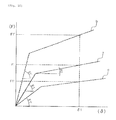
- a relationship between a tightening force that is applied to a metal gasket and an amount of displacement of the metal gasket is preferably a relationship that is indicated by the line a of a graph in Fig. 9.
- Fig. 9 is a graph for illustrating a preferable relationship between a tightening force F and a displacement amount ⁇ for a metal gasket.
- a relationship between a tightening force F and a displacement amount 5 for a metal gasket 100 of Patent Literature 3 described above is generally approximated to the line a of the graph in Fig. 9 .
- a vertical axis of the graph in Fig. 9 indicates a tightening force F and a horizontal axis of the graph in Fig. 9 indicates a displacement amount ⁇ of the metal gasket.
- an inclination of the line a of the graph indicates a rapid inclination E1 in the early stages.
- an inclination E1 in the early stages of Fig. 9 indicates a rapid inclination in such a manner that a tightening force F is as large as possible to a displacement amount ⁇ per unit.
- an inclination E2 of the line a of the graph indicates a gradual inclination after a tightening force F exceeds a predetermined tightening force F2.
- a metal gasket is used in the case in which a space between a flange 130 and a flange 132 is sealed as described above for instance in the case in which a space between two members is sealed.
- a tightening between flanges in this case is carried out until flanges come into contact with each other, that is, a metal touch of a flange face is carried out. That is, a tightening is carried out until the flanges 130 and 132 come into contact with each other in a state shown in Fig. 8 described above.
- the metal gasket 100 is compressed by a displacement amount ⁇ 1.
- a metal gasket is tightened until a metal touch of a flange face is carried out
- a tightening force F1 in the case of a metal touch is increased extremely and it is difficult to manage a tightening of a metal gasket.
- a symbol F0 indicates a tightening force that is required to obtain a predetermined sealing performance
- a symbol F2 indicates a tightening force in the case in which an inclination of the line a of the graph is changed from a rapid inclination E1 to gradual inclination E2.
- the tightening force F0 is smaller than a tightening force F1 in the case of a metal touch as a matter of course, and the tightening force F0 is smaller than a tightening force F2 described above. This is important to obtain a stable sealing performance for a metal gasket.
- an inclination E1 of the line of the graph indicates a rapid inclination in the early stages in such a manner that a tightening force F is increased per unit displacement amount.
- an inclination E2 of the line of the graph indicates a gradual inclination in such a manner that a tightening force F is decreased per unit displacement amount in the state in which a tightening force is larger than F0 and the metal gasket obtains a predetermined sealing performance.
- a line b and a line c of a graph of Fig. 10 are lines that indicate a relationship between a tightening force and a displacement amount for a conventional general metal gasket that is disclosed in Patent Literatures 1 and 2.
- a tightening force F1' in the case of a metal touch is increased in general.
- a tightening force F1' in the case of a metal touch is tried to be decreased, a tightening force F1' in the early stages is gradual in general as shown in the line c of the graph of Fig. 10 .
- a metal gasket can be made obtain a sealing performance almost equal to that of a metal gasket that is disclosed in Patent Literature 3 with a tightening force smaller than that of a metal gasket 100 that is disclosed in Patent Literature 3 by modifying a cross sectional shape of an inner ring 120 of the metal gasket 100 that is disclosed in Patent Literature 3.
- the present inventors have examined a relationship between inner angles ⁇ 1 and ⁇ 2 and a tightening force and a displacement amount for a metal gasket 100 that is disclosed in Patent Literature 3 shown in Figs. 7 and 8 .
- an inclination E in the early stages tends to be increased but a tightening force F1 in the case of a metal touch tends to be increased in the case in which an inner angle ⁇ 1 of the upper corner part 122a and the lower corner part 122b is decreased and a tightening force F1 in the case of a metal touch tends to be decreased in the case in which an inner angle ⁇ 2 of the inner-circumference-side corner part 122c and the outer-circumference-side corner 122d is decreased, and have completed the present invention.
- a metal gasket in accordance with the present invention is characterized by an annular metal gasket for sealing a space between members by being pressed in the vertical direction in a state of being mounted between the members, the metal gasket comprising an annular outer ring having a substantially C-shaped cross-section and having a circumferential-direction opening formed therein; and an annular inner ring fitted inside the outer ring, wherein the inner ring is formed so as to have a polygonal cross-section comprising:
- a metal gasket can be provided in which it obtains a sealing performance almost equal to that of a metal gasket that is disclosed in Patent Literature 3 with a tightening force smaller than that of a metal gasket that is disclosed in Patent Literature 3 shown in Figs. 7 and 8 .
- a metal gasket can be provided in which a tightening management of the metal gasket can be easily carried out since a tightening force until a metal touch can be decreased as compared with a metal gasket that is disclosed in Patent Literature 3 shown in Figs. 7 and 8 .
- a cross section of the inner ring is formed in a line symmetric shape in a vertical direction.
- the inner ring in the case in which a metal gasket is pressed in a vertical direction, the inner ring is deformed in a generally line symmetric shape in a vertical direction and in a horizontal direction of the cross section. Consequently, the inner ring can be prevented from being shifted or inclined at an angle, whereby the inner ring can be held on the inside of the outer ring in a stable state.
- the metal gasket in accordance with the present invention is characterized by further comprising a second bend part having an inside angle smaller than 180° between the upper corner part and the bend part formed between the upper corner part and the inner-circumference-side corner part, between the upper corner part and the bend part formed between the upper corner part and the outer-circumference-side corner part, between the lower corner part and the bend part formed between the upper corner part and the inner-circumference-side corner part, and between the lower corner part and the bend part formed between the upper corner part and the outer-circumference-side corner part.
- a metal gasket can be provided in which it obtains a sealing performance almost equal to that of a metal gasket that is disclosed in Patent Literature 3 shown in Figs. 7 and 8 with a smaller tightening force. Moreover, a metal gasket can be provided in which a tightening management of the metal gasket can be more easily carried out since a tightening force until a metal touch can be decreased.
- a metal gasket can be provided in which it obtains a sealing performance almost equal to that of a metal gasket that is disclosed in Patent Literature 3 describing a prior art with a tightening force smaller than that of a metal gasket that is disclosed in Patent Literature 3 describing a prior art shown in Figs. 7 and 8 .
- a tightening force can be made smaller than that of a conventional metal gasket, a flange can be thinned, an apparatus can be made compact and light, and a cost can be reduced.
- a material such as ceramics
- a material that may be easily damaged as compared with a metal can also be used as a material of a flange.
- a metal gasket can be provided in which a tightening management of the metal gasket can be easily carried out since a tightening force until a metal touch can be decreased as compared with a metal gasket that is disclosed in Patent Literature 3 describing a prior art shown in Figs. 7 and 8 .
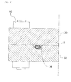
- Fig. 1 is a partially enlarged cross-sectional view showing a state in which a metal gasket in accordance with the present invention is used for a joint part of piping or the like.
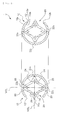
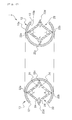
- Fig. 2 is a cross-sectional view showing a metal gasket in accordance with the present invention.
- a metal gasket 1 in accordance with the present invention is used for a joint part of a variety of piping of semiconductor manufacturing equipment. As shown in Fig. 1 , the metal gasket 1 is mounted to a sealing groove 34 that is formed in a flange 32, and is disposed between a flange 30 and the flange 32. The metal gasket 1 is pressed in a vertical direction by being tightened with a bolt 40 until a metal touch of the flange 30 and the flange 32 is carried out. By this configuration, a space between the flange 30 and the flange 32 is sealed.
- the metal gasket 1 in accordance with the present invention is provided with an annular outer ring 10 and an annular inner ring 20 that has been fitted inside the outer ring 10.
- an opening 12 is formed in a circumferential direction on the circumferential side of an outside surface 10a and having a substantially C-shaped cross-section as shown in Fig. 2 .
- the inner ring 20 is formed in a polygonal shape of a cross sectional hollow. Moreover, an upper corner part 22a that makes contact with an upper side of an inside surface 10b of the outer ring 10 and a lower corner part 22b that makes contact with a lower side of an inside surface 10b of the outer ring 10 are formed on the upper side of the cross section.
- An inner-circumference-side corner part 22c is formed on an inner circumference side between the upper corner part 22a and the lower corner part 22b, and an outer-circumference-side corner 22d is formed on an outer circumference side between the upper corner part 22a and the lower corner part 22b.
- an upper side of an inside surface 10b of the outer ring 10 indicates a part on the upper side of the opening 12.
- the upper side of an inside surface 10b of the outer ring 10 indicates an inside surface 10b that is located on the upper side of an upper end part 12a of the opening 12 for the inside surface 10b of the outer ring 10 in Fig. 2 .
- a lower side of an inside surface 10b of the outer ring 10 indicates a part on the lower side of the opening 12.
- the lower side of an inside surface 10b of the outer ring 10 indicates an inside surface 10b that is located on the lower side of a lower end part 12b of the opening 12 for the inside surface 10b of the outer ring 10.
- the inner-circumference-side corner part 22c of the inner ring 20 comes into contact with the inside surface 10b of the outer ring 10.
- a top part of each bend part of the upper corner part 22a, the lower corner part 22b, the inner-circumference-side corner part 22c, and the outer-circumference-side corner part 22d is formed in a circular arc shape.
- a top part of the bend part of the upper corner part 22a and the lower corner part 22b that comes into contact with the inside surface 10b of the outer ring 10 is formed in a circular arc shape in order to prevent the inside surface 10b of the outer ring 10 from being damaged.
- two bend parts of a bend part 24 and a second bend part 26 are formed from a part closer to the inner-circumference-side corner part 22c or the outer-circumference-side corner part 22d between the upper corner part 22a and the inner-circumference-side corner part 22c and the outer-circumference-side corner part 22d. Furthermore, two bend parts of a bend part 24 and a second bend part 26 are also formed from a part closer to the inner-circumference-side corner part 22c or the outer-circumference-side corner part 22d between the lower corner part 22b and the inner-circumference-side corner part 22c and the outer-circumference-side corner part 22d.
- the bend part 24 is bent toward an inside of a cross section of the inner ring 20, and an inside angle of the bend part 24 is larger than 180°.
- the second bend part 26 is bent toward an outside of a cross section of the inner ring 20, and an inside angle of the second bend part 26 is smaller than 180°.
- the upper corner part 22a described above comes into contact with the highest side part of the inside surface 10b of the outer ring 10
- the lower corner part 22b described above comes into contact with the lowest side part of the inside surface 10b of the outer ring 10.
- a contact part of the upper corner part 22a, the lower corner part 22b, and the inside surface 10b of the outer ring 10 is not restricted to the part described above.
- the upper corner part 22a comes into contact with the highest side part of the inside surface 10b of the outer ring 10 and the lower corner part 22b comes into contact with the lowest side part of the inside surface 10b of the outer ring 10 as described above since a pressing force is also applied to the inner ring 20 on the instant via the outer ring 10 in the case in which the metal gasket 1 is pressed in a vertical direction.
- a cross section of the inner ring 20 is formed in a line symmetric shape in a vertical direction and in a horizontal direction.
- the cross section of the inner ring 20 is formed in a symmetric shape in a vertical direction to the center line HCL in a horizontal direction and is formed in a symmetric shape in a horizontal direction to the center line VCL in a vertical direction as shown in Fig. 2 .
- An inner angle ⁇ 1 of the upper corner part 22a and that of the lower corner part 22b are equal to each other, and an inner angle ⁇ 2 of the inner-circumference-side corner part 22c and that of the outer-circumference-side corner part 22d are equal to each other.
- a cross section of the inner ring 20 is not restricted to be in a line symmetric shape in a vertical direction and in a horizontal direction.
- a cross section of the inner ring 20 is formed in a line symmetric shape at least in a vertical direction as described above since the inner ring 20 can be prevented from being shifted or inclined at an angle whereby the inner ring 20 can be held on the inside of the outer ring 10 in a stable state in the case in which the metal gasket 1 is pressed in a vertical direction as described later.
- a reason that the bend part 24 and the second bend part 26 as described above are formed is in the following. As described above, the present inventors have examined and found that a tightening force F1 in the case of a metal touch tends to be decreased in the case in which an inner angle ⁇ 2 of the inner-circumference-side corner part 122c and the outer-circumference-side corner 122d is decreased.
- a bend part 24 having an inside angle larger than 180° is formed between the upper corner part 22a and the inner-circumference-side corner part 22c and the outer-circumference-side corner part 22d and between the lower corner part 22b and inner-circumference-side corner part 22c and the outer-circumference-side corner part 22d, whereby an inner angle ⁇ 2 of the inner-circumference-side corner part 22c and the outer-circumference-side corner 22d is decreased.
- a tightening force F1 in the case of a metal touch tends to be increased extremely in the case in which an inner angle ⁇ 1 of the upper corner part 22a and the lower corner part 22b is decreased.
- an inner angle ⁇ 2 of the inner-circumference-side corner part 22c and the outer-circumference-side corner 22d is decreased and an inner angle ⁇ 1 of the upper corner part 22a and the lower corner part 22b is also decreased.
- a second bend part 26 having an inside angle smaller than 180° is formed between the upper corner part 22a and the lower corner part 22b and the bend part 24, whereby the inner angle ⁇ 1 of the upper corner part 22a and the lower corner part 22b is not too decreased.
- a bending degree of the second bend part 26 is smaller than that of the bend part 24.
- an outer angle of the second bend part 26 is smaller than the inner angle of the bend part 24.
- the inner angle ⁇ 1 of the upper corner part 22a and the lower corner part 22b is preferably in the range of 50° to 120°, more preferably in the range of 60° to 90°, depending on a shape and material of the metal gasket 1 and a displacement amount until a metal touch.
- the inner angle ⁇ 2 of the inner-circumference-side corner part 22c and the outer-circumference-side corner 22d is preferably 90° or less, more preferably in the range of 35° to 80°.
- the inner angle ⁇ 1 is about 75° and the inner angle ⁇ 2 is about 60°.
- a constitutional material of the outer ring 10 and the inner ring 20 is metal.
- metal that constitutes the inner ring 20 is a harder metal than metal that constitutes the outer ring 10.
- the outer ring 10 is made of aluminum that is called light metal and the inner ring 20 is made of metal harder than aluminum, such as stainless steel.
- the inner ring 20 is made of metal having a hardness degree higher than that of the outer ring 10 as described above and a metal gasket 1 in accordance with the present invention is disposed between the flanges 30 and 32 and pressed in a vertical direction as shown in Fig. 1 , the inner ring 20 that is hard to be deformed relatively and that has a high hardness degree strongly presses the outer ring 10 having a low hardness degree to the flanges 30 and 32.
- the outer ring 10 having a low hardness degree obtains a high sealing performance since the settlement to the flange 30 is excellent.
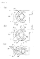
- Fig. 3 is a cross-sectional view showing a state in which a metal gasket in accordance with the present invention is pressed in a vertical direction and deformed.
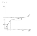
- Fig. 4 is a graph showing a relationship between a tightening force F and a displacement amount 5 for a metal gasket in accordance with the present invention.
- Fig. 3(a) indicates an initial state before the metal gasket 1 is deformed
- Fig. 3(b) indicates a state in which the metal gasket 1 is pressed and deformed and a predetermined sealing performance is obtained
- Fig. 3(c) indicates a state in which the metal gasket 1 is pressed and deformed until a metal touch of the metal gasket 1 is carried out.
- the symbols F0, F1, ⁇ 1, and ⁇ 2 in Fig. 3 are corresponded to tightening forces F0 and F1 and displacement amounts ⁇ 1 and ⁇ 2 that are shown in the graph of Fig. 4 , respectively.
- the inner angle ⁇ 1 is slightly increased and the inner angle ⁇ 1 is slightly decreased.
- a displacement amount ⁇ 2 of the metal gasket 1 in the state shown in Fig. 3(b) is mainly caused by a compressive deformation of a leading end part of the upper corner part 22a and the lower corner part 22b.
- the upper corner part 22a and the lower corner part 22b of the inner ring 20 are opened and deformed by slow degrees, and the inner angle ⁇ 1 is increased by slow degrees.
- the inner-circumference-side corner part 22c and the outer-circumference-side corner part 22d of the inner ring 20 are closed and deformed by slow degrees, and the inner angle ⁇ 2 is decreased by slow degrees.
- the inner ring 20 is pressed in a vertical direction and deformed, the bend part 24 on the upper side and the bend part 24 on the lower side come into contact with each other, and the inner angle ⁇ 2 of the inner-circumference-side corner part 22c and the outer-circumference-side corner part 22d becomes 0°.
- a compressive deformation by a displacement amount ⁇ 1 in a vertical direction is then carried out for the entire metal gasket 1.
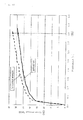
- Fig. 5 is a graph showing a result of an analysis of a relationship between a tightening force and a displacement amount using the finite element method in the case in which a metal gasket 1 shown in Fig. 2 in accordance with the present invention is an embodiment and a conventional metal gasket 100 shown in Fig. 7 in accordance with Patent Literature 3 is a comparison example.
- a vertical axis of the graph of Fig. 5 indicates a linear pressure and a horizontal axis of the graph indicates a displacement amount.
- linear pressure of a vertical axis of the graph is a tightening force per unit length that is applied to a metal gasket in the case in which the metal gasket is tightened and is defined as the following expression (1):
- Linear pressure tightening force ⁇ length of a central circumference of a metal gasket
- the condition of the metal gasket 1 of the embodiment is equivalent to that of the inner ring 120 of the comparison example except that the bend part 24 and the second bend part 26 described above are formed in the inner ring 20 of the embodiment.
- a material, a length of a central circumference, and a shape size of a cross section of the outer ring 10 of the embodiment and the outer ring 110 of the comparison example are specified as the same conditions, and a material, a length of a central circumference, and a thickness, height, and width of a cross section of the inner ring 20 of the embodiment and the inner ring 120 of the comparison example are specified as the same conditions.
- an inclination in the early stages is a rapid inclination for both the embodiment and the comparison example.
- an inclination in the state in which a linear pressure that is applied to the metal gasket is larger than F0 (15 KN/m in this embodiment) and the metal gasket obtains a predetermined sealing performance is a gradual inclination for the embodiment as compared with the comparison example.
- a linear pressure for a displacement amount ⁇ 1 (0.8 mm in this embodiment) in the case of a metal touch is 34.3 KN/m for the embodiment and 38.1 KN/m for the comparison example, that is, a linear pressure of the embodiment is decreased by about 10%.
- the metal gasket 1 in accordance with the present invention can obtain a sealing performance almost equal to that of a metal gasket that is disclosed in Patent Literature 3 with a tightening force smaller than that of the metal gasket 100 that is disclosed in Patent Literature 3.
- a tightening force can be made smaller than that of the metal gasket 100 that is disclosed in Patent Literature 3
- a flange can be thinned, an apparatus can be made compact and light, and a cost can be reduced.
- a material such as ceramics
- a material that may be easily damaged as compared with a metal can also be used as a material of a flange.
- a tightening management of the metal gasket 1 can be easily carried out since a tightening force F1 until a metal touch can be decreased as compared with the metal gasket 100 that is disclosed in Patent Literature 3.
- a bend part 24 having an inner angle smaller than 180° are formed between the upper corner part 22a and the inner- and outer-circumference-side corner parts 22c and 22d; and between the lower corner part 22b and the inner-and outer-circumference-side corner parts 22c and 22d at least.
- the opening 12 of the outer ring 10 is formed in a circumferential direction on the outer circumference side of the outside surface 10a.
- the metal gasket 1 in accordance with the present invention is not restricted to this configuration, the opening 12 of the outer ring 10 can also be formed in a circumferential direction on the inner circumference side of the outside surface 10a.
Landscapes
- Engineering & Computer Science (AREA)
- General Engineering & Computer Science (AREA)
- Mechanical Engineering (AREA)
- Gasket Seals (AREA)
Abstract
Description
- The present invention relates to a metal gasket that is suitable for being used in environments such as a high-temperature environment, a plasma environment, and an ultra-vacuum environment.
- An annular metal gasket that is called a metal C-ring gasket is used as a gasket that is used in environments such as a high-temperature environment, a plasma environment, and an ultra-vacuum environment in which a gasket made of rubber cannot be used for a variety of piping and mechanical equipment for nuclear facilities and semiconductor manufacturing equipment.
- A metal gasket that is called a metal C-ring gasket is configured in the manner in which an inner ring made of a metal leaf spring or a coil spring is fitted inside a metal outer ring having a substantially C-shaped cross-section as disclosed in the
Patent Literatures 1 and 2 for instance. Consequently, in the case in which the metal gasket is used, a tightening force larger than that for a gasket made of rubber is required, and a load in a tightening work and a fastening means such as a flange and a bolt are enlarged unfortunately. - Under such a background, this applicant has disclosed a metal gasket in which an inner ring is formed in a polygonal shape such as a square as an annular metal gasket in which a high sealing performance can be obtained by using a less tightening force (see Patent Literature 3).
-
Fig. 7 is a cross-sectional view showing a metal gasket that is disclosed in Patent Literature 3 describing a prior art.Fig. 8 is a cross-sectional view showing a state in which the metal gasket that is disclosed in Patent Literature 3 describing a prior art is mounted in a sealing groove. - As shown in
Fig. 7 , ametal gasket 100 of Patent Literature 3 is comprised of anouter ring 110 having a substantially C-shaped cross-section and having anopening 112 formed on a circumferential side and aninner ring 120 that is fitted inside theouter ring 110. As shown inFig. 7 , theinner ring 120 is formed so as to have a polygonal cross-section comprising a pair of anupper corner part 122a and alower corner part 122b in a vertical direction of the cross section and a pair of an inner-circumference-side corner part 122c and an outer-circumference-side corner 122d in a horizontal direction of the cross section. Theupper corner part 122a and thelower corner part 122b are fitted into theouter ring 110 so as to make contact with an inner side face of theouter ring 110. - As shown in
Fig. 8 , themetal gasket 100 of Patent Literature 3 is mounted in asealing groove 134 that is formed in aflange 132, and is pressed in a vertical direction with a tightening force F by aflange 130 on the other side. The pair of theupper corner part 122a and thelower corner part 122b described above then strongly presses an inner side face of theouter ring 110 by a restoring force of theinner ring 120, and the upper side of theouter ring 110 and theflange 130 are partially strongly made contact with each other. In addition, the lower side of theouter ring 110 and thesealing groove 134 of theflange 132 are partially strongly made contact with each other. A space between theflange 130 and theflange 132 is sealed in such a manner that the contact part functions as a sealing part. - As described above, the
metal gasket 100 of Patent Literature 3 describing a prior art is configured in such a manner that an inner side face of theouter ring 110 is pressed by theupper corner part 122a and thelower corner part 122b with a restoring force of theinner ring 120. Consequently, a high sealing performance can be obtained by a small tightening force as compared with a general metal gasket that is disclosed inPatent Literatures 1 and 2. - A relationship between a tightening force that is applied to a metal gasket and an amount of displacement of the metal gasket is preferably a relationship that is indicated by the line a of a graph in
Fig. 9. Fig. 9 is a graph for illustrating a preferable relationship between a tightening force F and a displacement amount δ for a metal gasket. A relationship between a tightening force F and adisplacement amount 5 for ametal gasket 100 of Patent Literature 3 described above is generally approximated to the line a of the graph inFig. 9 . A vertical axis of the graph inFig. 9 indicates a tightening force F and a horizontal axis of the graph inFig. 9 indicates a displacement amount δ of the metal gasket. - As shown by the line a of the graph in
Fig. 9 , for a relationship between a tightening force F and a displacement amount δ for a metal gasket, it is preferable that an inclination of the line a of the graph indicates a rapid inclination E1 in the early stages. - This is because a settlement is required between a metal gasket and a flange face in order to obtain a certain level of sealing performance of a metal gasket and is it necessary that a large contact stress is applied to a sealing part of a metal gasket that comes into contact with a flange face in order to obtain the settlement. In order to apply a large contact stress to a sealing part of a metal gasket, it is preferable that an inclination E1 in the early stages of
Fig. 9 indicates a rapid inclination in such a manner that a tightening force F is as large as possible to a displacement amount δ per unit. - In the case in which an inclination E1 in the early stages is gradual, it is necessary that a metal gasket is deformed greatly to apply a large contact stress to a sealing part of a metal gasket. In the case in which a tightening of a bolt is insufficient, a sufficient settlement cannot be obtained between a metal gasket and a flange face in some cases. The settlement that is said here is that a metal gasket that comes into contact with a flange face is deformed along minute concavity and convexity of the flange face and a gap between a metal gasket and a flange face is removed by bridging the concavity and convexity.
- As shown by the line a of the graph of
Fig. 9 , for a relationship between a tightening force F and a displacement amount δ for a metal gasket, it is preferable that an inclination E2 of the line a of the graph indicates a gradual inclination after a tightening force F exceeds a predetermined tightening force F2. - This is because a metal gasket is used in the case in which a space between a
flange 130 and aflange 132 is sealed as described above for instance in the case in which a space between two members is sealed. A tightening between flanges in this case is carried out until flanges come into contact with each other, that is, a metal touch of a flange face is carried out. That is, a tightening is carried out until theflanges Fig. 8 described above. In a state in which a tightening is completed, themetal gasket 100 is compressed by a displacement amount δ1. - As described above, a metal gasket is tightened until a metal touch of a flange face is carried out In the case of a metal gasket in which an inclination E2 of the line a of the graph indicates a rapid inclination, a tightening force F1 in the case of a metal touch is increased extremely and it is difficult to manage a tightening of a metal gasket.
- In the case in which a management of a tightening of a metal gasket is carried out by a so-called displacement control in which a tightening is carried out until a displacement of a metal gasket becomes a predetermined displacement amount δ1, the following problems occur in some cases. In other words, an error occurs by a wave or a dimension tolerance of flange face and a sealing groove for a displacement amount of a metal touch. Therefore, in the case in which an inclination E2 of the line a of the graph indicates a rapid inclination, a tightening force is varied greatly only by a small error that occurs for a displacement amount of a metal touch. In the case in which a tightening force is decreased, a sealing performance may be deteriorated. In the case in which a tightening force is increased, a bolt is damaged or a tightening cannot be carried out until a metal touch unfortunately.
- In the graph shown in
Fig. 9 , a symbol F0 indicates a tightening force that is required to obtain a predetermined sealing performance, and a symbol F2 indicates a tightening force in the case in which an inclination of the line a of the graph is changed from a rapid inclination E1 to gradual inclination E2. The tightening force F0 is smaller than a tightening force F1 in the case of a metal touch as a matter of course, and the tightening force F0 is smaller than a tightening force F2 described above. This is important to obtain a stable sealing performance for a metal gasket. -
- [Patent Literature 1]
Japanese Patent Application Laid-Open Publication No.2-113171 - [Patent Literature 2]
Japanese Patent Application Laid-Open Publication No.9-264427 - [Patent Literature 3]
Japanese Patent Application Laid-Open Publication No.2009-281424 - As described above, for a relationship between a tightening force F and a displacement amount δ for a metal gasket, it is preferable that an inclination E1 of the line of the graph indicates a rapid inclination in the early stages in such a manner that a tightening force F is increased per unit displacement amount. Moreover, it is preferable that an inclination E2 of the line of the graph indicates a gradual inclination in such a manner that a tightening force F is decreased per unit displacement amount in the state in which a tightening force is larger than F0 and the metal gasket obtains a predetermined sealing performance.
- Moreover, to make a metal gasket obtain a higher sealing performance with a small tightening force, it is necessary that a tightening force F1 in the case of a metal touch is decreased while a relationship between a tightening force F and a displacement amount δ as described above is maintained.
- However, it is not easy to develop a metal gasket in which a tightening force F1 in the case of a metal touch is decreased while a relationship between a tightening force F and a
displacement amount 5 as described above is maintained. For instance, a line b and a line c of a graph ofFig. 10 are lines that indicate a relationship between a tightening force and a displacement amount for a conventional general metal gasket that is disclosed inPatent Literatures 1 and 2. As shown in the line b of the graph ofFig. 10 , in the case in which an inclination E1' of the line of the graph in the early stages is tried to be increased, a tightening force F1' in the case of a metal touch is increased in general. Moreover, a tightening force F1' in the case of a metal touch is tried to be decreased, a tightening force F1' in the early stages is gradual in general as shown in the line c of the graph ofFig. 10 . - Under such a technical background, the present inventors have thought that a metal gasket can be made obtain a sealing performance almost equal to that of a metal gasket that is disclosed in Patent Literature 3 with a tightening force smaller than that of a
metal gasket 100 that is disclosed in Patent Literature 3 by modifying a cross sectional shape of aninner ring 120 of themetal gasket 100 that is disclosed in Patent Literature 3. - Moreover, the present inventors have examined a relationship between inner angles θ1 and θ2 and a tightening force and a displacement amount for a
metal gasket 100 that is disclosed in Patent Literature 3 shown inFigs. 7 and8 . As a result, the present inventors have found that an inclination E in the early stages tends to be increased but a tightening force F1 in the case of a metal touch tends to be increased in the case in which an inner angle θ1 of theupper corner part 122a and thelower corner part 122b is decreased and a tightening force F1 in the case of a metal touch tends to be decreased in the case in which an inner angle θ2 of the inner-circumference-side corner part 122c and the outer-circumference-side corner 122d is decreased, and have completed the present invention. - 1. A metal gasket in accordance with the present invention is characterized by an annular metal gasket for sealing a space between members by being pressed in the vertical direction in a state of being mounted between the members, the metal gasket comprising an annular outer ring having a substantially C-shaped cross-section and having a circumferential-direction opening formed therein; and an annular inner ring fitted inside the outer ring,
wherein the inner ring is formed so as to have a polygonal cross-section comprising: - an upper corner part that makes contact with an upper side of an inside surface of the outer ring;
- a lower corner part that makes contact with a lower side of the inside surface of the outer ring;
- an inner-circumference-side corner part formed on an inner-circumference side of the inner ring so as to be positioned between the upper corner part and the lower corner part; and
- an outer-circumference-side corner formed on an outer-circumference side of the inner ring so as to be positioned between the upper corner part and the lower corner part, and
- bend parts having an inside angle larger than 180° are formed between the upper corner part and the inner- and outer-circumference-side corner parts; and between the lower corner part and the inner- and outer-circumference-side corner parts.
- By this configuration, a metal gasket can be provided in which it obtains a sealing performance almost equal to that of a metal gasket that is disclosed in Patent Literature 3 with a tightening force smaller than that of a metal gasket that is disclosed in Patent Literature 3 shown in
Figs. 7 and8 . - Moreover, a metal gasket can be provided in which a tightening management of the metal gasket can be easily carried out since a tightening force until a metal touch can be decreased as compared with a metal gasket that is disclosed in Patent Literature 3 shown in
Figs. 7 and8 . - In the above invention, it is preferable that a cross section of the inner ring is formed in a line symmetric shape in a vertical direction.
- By this configuration, in the case in which a metal gasket is pressed in a vertical direction, the inner ring is deformed in a generally line symmetric shape in a vertical direction and in a horizontal direction of the cross section. Consequently, the inner ring can be prevented from being shifted or inclined at an angle, whereby the inner ring can be held on the inside of the outer ring in a stable state.
- In the above invention, the metal gasket in accordance with the present invention is characterized by further comprising a second bend part having an inside angle smaller than 180° between the upper corner part and the bend part formed between the upper corner part and the inner-circumference-side corner part, between the upper corner part and the bend part formed between the upper corner part and the outer-circumference-side corner part, between the lower corner part and the bend part formed between the upper corner part and the inner-circumference-side corner part, and between the lower corner part and the bend part formed between the upper corner part and the outer-circumference-side corner part.
- By this configuration, a metal gasket can be provided in which it obtains a sealing performance almost equal to that of a metal gasket that is disclosed in Patent Literature 3 shown in
Figs. 7 and8 with a smaller tightening force. Moreover, a metal gasket can be provided in which a tightening management of the metal gasket can be more easily carried out since a tightening force until a metal touch can be decreased. - In accordance with the present invention, a metal gasket can be provided in which it obtains a sealing performance almost equal to that of a metal gasket that is disclosed in Patent Literature 3 describing a prior art with a tightening force smaller than that of a metal gasket that is disclosed in Patent Literature 3 describing a prior art shown in
Figs. 7 and8 . In accordance with the present invention, since a tightening force can be made smaller than that of a conventional metal gasket, a flange can be thinned, an apparatus can be made compact and light, and a cost can be reduced. Moreover, a material (such as ceramics) that may be easily damaged as compared with a metal can also be used as a material of a flange. - Moreover, a metal gasket can be provided in which a tightening management of the metal gasket can be easily carried out since a tightening force until a metal touch can be decreased as compared with a metal gasket that is disclosed in Patent Literature 3 describing a prior art shown in
Figs. 7 and8 . -
- [
Fig. 1 ]
Fig. 1 is a partially enlarged cross-sectional view showing a state in which a metal gasket in accordance with the present invention is used for a flange part of piping or the like. - [
Fig. 2 ]
Fig. 2 is a cross-sectional view showing a metal gasket in accordance with the present invention. - [
Fig. 3 ]
Fig. 3 is a cross-sectional view showing a state in which a metal gasket in accordance with the present invention is pressed in a vertical direction and deformed. - [
Fig. 4 ]
Fig. 4 is a graph showing a relationship between a tightening force F and a displacement amount δ for a metal gasket in accordance with the present invention. - [
Fig. 5 ]
Fig. 5 is a graph showing a result of an analysis of a relationship between a tightening force and a displacement amount using the finite element method in the case in which ametal gasket 1 in accordance with the present invention is an embodiment and ametal gasket 100 in accordance with Patent Literature 3 is a comparison example. - [
Fig. 6 ]
Fig. 6 is a cross-sectional view showing a metal gasket in accordance with another embodiment of the present invention. - [
Fig. 7 ]
Fig. 7 is a cross-sectional view showing a metal gasket that is disclosed in Patent Literature 3 describing a prior art. - [
Fig. 8 ]
Fig. 8 is a cross-sectional view showing a state in which the metal gasket that is disclosed in Patent Literature 3 describing a prior art is mounted in a sealing groove. - [
Fig. 9 ]
Fig. 9 is a graph for illustrating a preferable relationship between a tightening force F and a displacement amount δ for a metal gasket. - [
Fig. 10 ]
Fig. 10 is a graph for illustrating a relationship between a tightening force F and adisplacement amount 5 for a conventional general metal gasket. - An embodiment of the present invention will be described below in detail with reference to the drawings.
Fig. 1 is a partially enlarged cross-sectional view showing a state in which a metal gasket in accordance with the present invention is used for a joint part of piping or the like.Fig. 2 is a cross-sectional view showing a metal gasket in accordance with the present invention. - A
metal gasket 1 in accordance with the present invention is used for a joint part of a variety of piping of semiconductor manufacturing equipment. As shown inFig. 1 , themetal gasket 1 is mounted to a sealinggroove 34 that is formed in aflange 32, and is disposed between aflange 30 and theflange 32. Themetal gasket 1 is pressed in a vertical direction by being tightened with abolt 40 until a metal touch of theflange 30 and theflange 32 is carried out. By this configuration, a space between theflange 30 and theflange 32 is sealed. - As shown in
Fig. 2 , themetal gasket 1 in accordance with the present invention is provided with an annularouter ring 10 and an annularinner ring 20 that has been fitted inside theouter ring 10.
For theouter ring 10, anopening 12 is formed in a circumferential direction on the circumferential side of anoutside surface 10a and having a substantially C-shaped cross-section as shown inFig. 2 . - As shown in
Fig. 2 , theinner ring 20 is formed in a polygonal shape of a cross sectional hollow. Moreover, anupper corner part 22a that makes contact with an upper side of aninside surface 10b of theouter ring 10 and alower corner part 22b that makes contact with a lower side of aninside surface 10b of theouter ring 10 are formed on the upper side of the cross section. An inner-circumference-side corner part 22c is formed on an inner circumference side between theupper corner part 22a and thelower corner part 22b, and an outer-circumference-side corner 22d is formed on an outer circumference side between theupper corner part 22a and thelower corner part 22b. - Here, an upper side of an
inside surface 10b of theouter ring 10 indicates a part on the upper side of theopening 12. In other words, the upper side of aninside surface 10b of theouter ring 10 indicates aninside surface 10b that is located on the upper side of anupper end part 12a of theopening 12 for theinside surface 10b of theouter ring 10 inFig. 2 . Similarly, a lower side of aninside surface 10b of theouter ring 10 indicates a part on the lower side of theopening 12. In other words, the lower side of aninside surface 10b of theouter ring 10 indicates aninside surface 10b that is located on the lower side of alower end part 12b of theopening 12 for theinside surface 10b of theouter ring 10. InFig. 2 , the inner-circumference-side corner part 22c of theinner ring 20 comes into contact with theinside surface 10b of theouter ring 10. However, it is not always necessary that the inner-circumference-side corner part 22c comes into contact with theinside surface 10b of theouter ring 10. - It is preferable that a top part of each bend part of the
upper corner part 22a, thelower corner part 22b, the inner-circumference-side corner part 22c, and the outer-circumference-side corner part 22d is formed in a circular arc shape. In particular, it is preferable that a top part of the bend part of theupper corner part 22a and thelower corner part 22b that comes into contact with theinside surface 10b of theouter ring 10 is formed in a circular arc shape in order to prevent theinside surface 10b of theouter ring 10 from being damaged. - Moreover, two bend parts of a
bend part 24 and asecond bend part 26 are formed from a part closer to the inner-circumference-side corner part 22c or the outer-circumference-side corner part 22d between theupper corner part 22a and the inner-circumference-side corner part 22c and the outer-circumference-side corner part 22d. Furthermore, two bend parts of abend part 24 and asecond bend part 26 are also formed from a part closer to the inner-circumference-side corner part 22c or the outer-circumference-side corner part 22d between thelower corner part 22b and the inner-circumference-side corner part 22c and the outer-circumference-side corner part 22d. - As shown in
Fig. 2 , thebend part 24 is bent toward an inside of a cross section of theinner ring 20, and an inside angle of thebend part 24 is larger than 180°. On the other hand, thesecond bend part 26 is bent toward an outside of a cross section of theinner ring 20, and an inside angle of thesecond bend part 26 is smaller than 180°. - For the
inner ring 20 shown inFig. 2 , theupper corner part 22a described above comes into contact with the highest side part of theinside surface 10b of theouter ring 10, and thelower corner part 22b described above comes into contact with the lowest side part of theinside surface 10b of theouter ring 10. - For the
metal gasket 1 in accordance with the present invention, a contact part of theupper corner part 22a, thelower corner part 22b, and theinside surface 10b of theouter ring 10 is not restricted to the part described above. However, it is preferable that theupper corner part 22a comes into contact with the highest side part of theinside surface 10b of theouter ring 10 and thelower corner part 22b comes into contact with the lowest side part of theinside surface 10b of theouter ring 10 as described above since a pressing force is also applied to theinner ring 20 on the instant via theouter ring 10 in the case in which themetal gasket 1 is pressed in a vertical direction. - A cross section of the
inner ring 20 is formed in a line symmetric shape in a vertical direction and in a horizontal direction. In other words, the cross section of theinner ring 20 is formed in a symmetric shape in a vertical direction to the center line HCL in a horizontal direction and is formed in a symmetric shape in a horizontal direction to the center line VCL in a vertical direction as shown inFig. 2 . An inner angle θ1 of theupper corner part 22a and that of thelower corner part 22b are equal to each other, and an inner angle θ2 of the inner-circumference-side corner part 22c and that of the outer-circumference-side corner part 22d are equal to each other. - For the
metal gasket 1 in accordance with the present invention, a cross section of theinner ring 20 is not restricted to be in a line symmetric shape in a vertical direction and in a horizontal direction. However, it is preferable that a cross section of theinner ring 20 is formed in a line symmetric shape at least in a vertical direction as described above since theinner ring 20 can be prevented from being shifted or inclined at an angle whereby theinner ring 20 can be held on the inside of theouter ring 10 in a stable state in the case in which themetal gasket 1 is pressed in a vertical direction as described later. - For the
metal gasket 1 in accordance with the present invention, a reason that thebend part 24 and thesecond bend part 26 as described above are formed is in the following.
As described above, the present inventors have examined and found that a tightening force F1 in the case of a metal touch tends to be decreased in the case in which an inner angle θ2 of the inner-circumference-side corner part 122c and the outer-circumference-side corner 122d is decreased. Consequently, for themetal gasket 1 in accordance with the present invention, abend part 24 having an inside angle larger than 180° is formed between theupper corner part 22a and the inner-circumference-side corner part 22c and the outer-circumference-side corner part 22d and between thelower corner part 22b and inner-circumference-side corner part 22c and the outer-circumference-side corner part 22d, whereby an inner angle θ2 of the inner-circumference-side corner part 22c and the outer-circumference-side corner 22d is decreased. - In addition, the present inventors have examined and found that a tightening force F1 in the case of a metal touch tends to be increased extremely in the case in which an inner angle θ1 of the
upper corner part 22a and thelower corner part 22b is decreased. In the case in which thebend part 24 as described above is formed, an inner angle θ2 of the inner-circumference-side corner part 22c and the outer-circumference-side corner 22d is decreased and an inner angle θ1 of theupper corner part 22a and thelower corner part 22b is also decreased. Consequently, for themetal gasket 1 in accordance with the present invention, asecond bend part 26 having an inside angle smaller than 180° is formed between theupper corner part 22a and thelower corner part 22b and thebend part 24, whereby the inner angle θ1 of theupper corner part 22a and thelower corner part 22b is not too decreased. - It is preferable that a bending degree of the
second bend part 26 is smaller than that of thebend part 24. In other words, it is preferable that an outer angle of thesecond bend part 26 is smaller than the inner angle of thebend part 24. In the case in which thesecond bend part 26 is bent greatly, theupper corner part 22a and thelower corner part 22b are concaved inside and deformed in the state shown inFig. 3(C) described later for instance. Consequently, a contact stress of theupper corner part 22a and thelower corner part 22b and theinside surface 10b of theouter ring 10 is decreased, whereby a sealing performed may be deteriorated. - The inner angle θ1 of the
upper corner part 22a and thelower corner part 22b is preferably in the range of 50° to 120°, more preferably in the range of 60° to 90°, depending on a shape and material of themetal gasket 1 and a displacement amount until a metal touch. Moreover, the inner angle θ2 of the inner-circumference-side corner part 22c and the outer-circumference-side corner 22d is preferably 90° or less, more preferably in the range of 35° to 80°. In the present embodiment, the inner angle θ1 is about 75° and the inner angle θ2 is about 60°. - A constitutional material of the
outer ring 10 and theinner ring 20 is metal. In this case, it is preferable that metal that constitutes theinner ring 20 is a harder metal than metal that constitutes theouter ring 10. For instance, it is preferable that theouter ring 10 is made of aluminum that is called light metal and theinner ring 20 is made of metal harder than aluminum, such as stainless steel. - In the case in which the
inner ring 20 is made of metal having a hardness degree higher than that of theouter ring 10 as described above and ametal gasket 1 in accordance with the present invention is disposed between theflanges Fig. 1 , theinner ring 20 that is hard to be deformed relatively and that has a high hardness degree strongly presses theouter ring 10 having a low hardness degree to theflanges outer ring 10 having a low hardness degree obtains a high sealing performance since the settlement to theflange 30 is excellent. - Moreover, in the case in which a soft layer (not shown) that is formed by coating polytetrafluoroethylene (PTFE) or polyimide or plating silver, nickel, or copper is formed on the
outside surface 10a of theouter ring 10, the settlement to theflange 30 of theouter ring 10 is more excellent, and theouter ring 10 obtains a higher sealing performance, -
Fig. 3 is a cross-sectional view showing a state in which a metal gasket in accordance with the present invention is pressed in a vertical direction and deformed.Fig. 4 is a graph showing a relationship between a tightening force F and adisplacement amount 5 for a metal gasket in accordance with the present invention. Here,Fig. 3(a) indicates an initial state before themetal gasket 1 is deformed,Fig. 3(b) indicates a state in which themetal gasket 1 is pressed and deformed and a predetermined sealing performance is obtained, andFig. 3(c) indicates a state in which themetal gasket 1 is pressed and deformed until a metal touch of themetal gasket 1 is carried out. The symbols F0, F1, δ1, and δ2 inFig. 3 are corresponded to tightening forces F0 and F1 and displacement amounts δ1 and δ2 that are shown in the graph ofFig. 4 , respectively. - As shown in
Fig. 3 , in the case in which themetal gasket 1 is pressed in a vertical direction in the initial state shown inFig. 3(a) , a leading end part of theupper corner part 22a and thelower corner part 22b of theinner ring 20 is pressed and deformed in the first place. A compressive deformation by a displacement amount δ2 in a vertical direction is then carried out for theentire metal gasket 1 to enter the state shown inFig. 3(b) . In this state, an inner angle θ1 of theupper corner part 22a and thelower corner part 22b and an inner angle θ2 of the inner-circumference-side corner part 22c and the outer-circumference-side corner part 22d are hardly changed from their initial state. The inner angle θ1 is slightly increased and the inner angle θ1 is slightly decreased. In other words, a displacement amount δ2 of themetal gasket 1 in the state shown inFig. 3(b) is mainly caused by a compressive deformation of a leading end part of theupper corner part 22a and thelower corner part 22b. - In the case in which the
metal gasket 1 is still pressed while a tightening force F is increased, theupper corner part 22a and thelower corner part 22b of theinner ring 20 are opened and deformed by slow degrees, and the inner angle θ1 is increased by slow degrees. Moreover, the inner-circumference-side corner part 22c and the outer-circumference-side corner part 22d of theinner ring 20 are closed and deformed by slow degrees, and the inner angle θ2 is decreased by slow degrees. In a definitive fashion as shown inFig. 3(c) , theinner ring 20 is pressed in a vertical direction and deformed, thebend part 24 on the upper side and thebend part 24 on the lower side come into contact with each other, and the inner angle θ2 of the inner-circumference-side corner part 22c and the outer-circumference-side corner part 22d becomes 0°. A compressive deformation by a displacement amount δ1 in a vertical direction is then carried out for theentire metal gasket 1. - In this case, until the
metal gasket 1 is deformed by a predetermined displacement amount δ2 from the initial state, a large tightening force F is required to a displacement amount per unit. In other words, as shown inFig. 4 , an inclination in the early stages for a line a of the graph is a rapid inclination E1. On the other hand, until a displacement amount of themetal gasket 1 is changed from δ2 to δ1, a deformation is carried out by a small tightening force F to a displacement amount per unit. In other words, as shown inFig. 4 , an inclination E1 in the early stages for a line a of the graph is a gradual inclination E2. -
Fig. 5 is a graph showing a result of an analysis of a relationship between a tightening force and a displacement amount using the finite element method in the case in which ametal gasket 1 shown inFig. 2 in accordance with the present invention is an embodiment and aconventional metal gasket 100 shown inFig. 7 in accordance with Patent Literature 3 is a comparison example. A vertical axis of the graph ofFig. 5 indicates a linear pressure and a horizontal axis of the graph indicates a displacement amount. - The linear pressure of a vertical axis of the graph is a tightening force per unit length that is applied to a metal gasket in the case in which the metal gasket is tightened and is defined as the following expression (1):

- In the finite element analysis, for the
metal gasket 1 in accordance with the embodiment and themetal gasket 100 in accordance with the comparison example, while theinner ring 120 of the comparison example is formed in a square shape, the condition of themetal gasket 1 of the embodiment is equivalent to that of theinner ring 120 of the comparison example except that thebend part 24 and thesecond bend part 26 described above are formed in theinner ring 20 of the embodiment. In other words, a material, a length of a central circumference, and a shape size of a cross section of theouter ring 10 of the embodiment and theouter ring 110 of the comparison example are specified as the same conditions, and a material, a length of a central circumference, and a thickness, height, and width of a cross section of theinner ring 20 of the embodiment and theinner ring 120 of the comparison example are specified as the same conditions. - As shown in
Fig. 5 , an inclination in the early stages is a rapid inclination for both the embodiment and the comparison example. This means that themetal gasket 1 in accordance with the embodiment has a sealing performance almost equivalent to that of themetal gasket 100 in accordance with the comparison example. - As shown in
Fig. 5 , an inclination in the state in which a linear pressure that is applied to the metal gasket is larger than F0 (15 KN/m in this embodiment) and the metal gasket obtains a predetermined sealing performance is a gradual inclination for the embodiment as compared with the comparison example. Moreover, a linear pressure for a displacement amount δ1 (0.8 mm in this embodiment) in the case of a metal touch is 34.3 KN/m for the embodiment and 38.1 KN/m for the comparison example, that is, a linear pressure of the embodiment is decreased by about 10%. - As described above, the
metal gasket 1 in accordance with the present invention can obtain a sealing performance almost equal to that of a metal gasket that is disclosed in Patent Literature 3 with a tightening force smaller than that of themetal gasket 100 that is disclosed in Patent Literature 3. As described above, for themetal gasket 1 in accordance with the present invention, since a tightening force can be made smaller than that of themetal gasket 100 that is disclosed in Patent Literature 3, a flange can be thinned, an apparatus can be made compact and light, and a cost can be reduced. Moreover, a material (such as ceramics) that may be easily damaged as compared with a metal can also be used as a material of a flange. - Moreover, for the
metal gasket 1 in accordance with the present invention, a tightening management of themetal gasket 1 can be easily carried out since a tightening force F1 until a metal touch can be decreased as compared with themetal gasket 100 that is disclosed in Patent Literature 3. - While the preferred embodiments in accordance with the present invention have been described above, the present invention is not restricted to the embodiments, and various changes, modifications, and functional additions can be thus made without departing from the scope of the present invention.
For instance, although two bend parts of thebend part 24 and the second bend part26 are formed in the embodiment described above, the present invention is not restricted to this configuration. As shown inFig. 6 , abend part 24 having an inner angle smaller than 180° are formed between theupper corner part 22a and the inner- and outer-circumference-side corner parts lower corner part 22b and the inner-and outer-circumference-side corner parts - Moreover, in the embodiment described above, the
opening 12 of theouter ring 10 is formed in a circumferential direction on the outer circumference side of theoutside surface 10a. However, themetal gasket 1 in accordance with the present invention is not restricted to this configuration, theopening 12 of theouter ring 10 can also be formed in a circumferential direction on the inner circumference side of theoutside surface 10a. -
- 1: Metal gasket
- 10: Outer ring
- 10a: Outside surface of the outer ring
- 10b: Inside surface of the outer ring
- 12: Opening
- 12a: Upper end part of the opening
- 12b: Lower end part of the opening
- 20: Inner ring
- 22a: Upper corner part
- 22b: Lower corner part
- 22c: Inner-circumference-side corner part
- 22d: Outer-circumference-side corner part
- 24: Bend part
- 26: Second bend part
- 30 and 32: Flanges
- 34: Sealing groove
- 40: Bolt
- 100: Metal gasket
- 110: Outer ring
- 112: Opening
- 120: Inner ring
- 122a: Upper corner part
- 122b: Lower corner part
- 122c: Inner-circumference-side corner part
- 122d: Outer-circumference-side corner part
- 130 and 132: Flanges
- 134: Sealing groove
- θ1: Inner angle of the upper corner part and the lower corner part
- θ2: Inner angle of the inner-circumference-side corner part and the outer-circumference-side corner part
Claims (3)
- An annular metal gasket for sealing a space between members by being pressed in the vertical direction in a state of being mounted between the members, the metal gasket comprising an annular outer ring having a substantially C-shaped cross-section and having a circumferential-direction opening formed therein; and an annular inner ring fitted inside the outer ring,
wherein the inner ring is formed so as to have a polygonal cross-section comprising:an upper corner part that makes contact with an upper side of an inside surface of the outer ring;a lower corner part that makes contact with a lower side of the inside surface of the outer ring;an inner-circumference-side corner part formed on an inner-circumference side of the inner ring so as to be positioned between the upper corner part and the lower corner part; andan outer-circumference-side corner part formed on an outer-circumference side of the inner ring so as to be positioned between the upper corner part and the lower corner part, andbend parts having an inner angle larger than 180° are formed between the upper corner part and the inner- andouter-circumference-side corner parts; and between the lower corner part and the inner- and outer-circumference-side corner parts. - A metal gasket as defined in claim 1, wherein a cross section of the inner ring is formed in a line symmetric shape in a vertical direction.
- A metal gasket as defined in claim 1 or 2, further comprising a second bend part having an inside angle smaller than 180° between the upper corner part and the bend part formed between the upper corner part and the inner-circumference-side corner part, between the upper corner part and the bend part formed between the upper corner part and the outer-circumference-side corner part, between the lower corner part and the bend part formed between the upper corner part and the inner-circumference-side corner part, and between the lower corner part and the bend part formed between the upper corner part and the outer-circumference-side corner part.
Applications Claiming Priority (2)
| Application Number | Priority Date | Filing Date | Title |
|---|---|---|---|
| JP2011011984A JP5638401B2 (en) | 2011-01-24 | 2011-01-24 | Metal gasket |
| PCT/JP2012/050429 WO2012102082A1 (en) | 2011-01-24 | 2012-01-12 | Metal gasket |
Publications (2)
| Publication Number | Publication Date |
|---|---|
| EP2669553A1 true EP2669553A1 (en) | 2013-12-04 |
| EP2669553A4 EP2669553A4 (en) | 2016-08-24 |
Family
ID=46580655
Family Applications (1)
| Application Number | Title | Priority Date | Filing Date |
|---|---|---|---|
| EP12739353.6A Withdrawn EP2669553A4 (en) | 2011-01-24 | 2012-01-12 | METAL TRIM |
Country Status (6)
| Country | Link |
|---|---|
| US (1) | US8807573B2 (en) |
| EP (1) | EP2669553A4 (en) |
| JP (1) | JP5638401B2 (en) |
| KR (1) | KR101489615B1 (en) |
| CN (1) | CN103282701B (en) |
| WO (1) | WO2012102082A1 (en) |
Cited By (2)
| Publication number | Priority date | Publication date | Assignee | Title |
|---|---|---|---|---|
| WO2024184547A1 (en) * | 2023-03-09 | 2024-09-12 | Tokamak Energy Ltd | Sealing ring and method of forming a metal-to-metal seal |
| EP4632252A1 (en) * | 2024-04-08 | 2025-10-15 | Goodrich Corporation | Seal |
Families Citing this family (6)
| Publication number | Priority date | Publication date | Assignee | Title |
|---|---|---|---|---|
| JP6257277B2 (en) * | 2013-11-13 | 2018-01-10 | 三菱電線工業株式会社 | Metal seal |
| JP6309284B2 (en) * | 2014-01-27 | 2018-04-11 | 三菱電線工業株式会社 | Metal seal |
| US20160091092A1 (en) * | 2014-09-25 | 2016-03-31 | Atlas Bimetal Labs, Inc. | Deformable all metal gaskets for ultra high purity sealing |
| US10460845B2 (en) * | 2015-11-16 | 2019-10-29 | Ge-Hitachi Nuclear Energy Americas Llc | Nuclear reactor flow path sealing systems and seals |
| WO2022085577A1 (en) * | 2020-10-20 | 2022-04-28 | 株式会社バルカー | Metal gasket |
| KR20220076798A (en) | 2020-12-01 | 2022-06-08 | 현대자동차주식회사 | Variable back-up ring and sealing structure having the same |
Family Cites Families (13)
| Publication number | Priority date | Publication date | Assignee | Title |
|---|---|---|---|---|
| US2701155A (en) * | 1951-02-19 | 1955-02-01 | Globe Hoist Co | Oil seal unit and expander ring therefor |
| DE1216634B (en) | 1963-08-16 | 1966-05-12 | Goetzewerke | Sealing for flanges, especially cylinder heads |
| GB1305366A (en) | 1971-05-28 | 1973-01-31 | ||
| US4026197A (en) * | 1975-06-02 | 1977-05-31 | Caterpillar Tractor Co. | Oil cooled piston rings |
| US4218067A (en) | 1979-02-02 | 1980-08-19 | Pressure Science Incorporated | Multi-ply sealing rings |
| FR2636115B1 (en) | 1988-09-08 | 1990-10-19 | Commissariat Energie Atomique | HIGHLY SPECIFIC PRESSURE METAL GASKET |
| JPH02309063A (en) | 1989-05-24 | 1990-12-25 | Canon Inc | Vacuum seal device |
| JPH0932928A (en) * | 1995-07-17 | 1997-02-07 | Nippon Valqua Ind Ltd | Metal gasket and method of manufacturing metal gasket |
| JP3110307B2 (en) | 1996-03-28 | 2000-11-20 | 日本バルカー工業株式会社 | Metal gasket |
| FR2823826B1 (en) | 2001-04-23 | 2003-07-25 | Commissariat Energie Atomique | FLEXIBLE ELASTIC METALLIC SEAL WITH HIGH-SPEED PARTS |
| US7451989B1 (en) * | 2005-01-25 | 2008-11-18 | Parker-Hannifin Corporation | Seal |
| BRPI0622040A2 (en) * | 2006-09-27 | 2014-07-01 | Masato Nagawa | GASKET |
| JP5204550B2 (en) | 2008-05-20 | 2013-06-05 | 国立大学法人東北大学 | Metal gasket |
-
2011
- 2011-01-24 JP JP2011011984A patent/JP5638401B2/en active Active
-
2012
- 2012-01-12 KR KR1020137020737A patent/KR101489615B1/en active Active
- 2012-01-12 WO PCT/JP2012/050429 patent/WO2012102082A1/en not_active Ceased
- 2012-01-12 US US13/981,218 patent/US8807573B2/en active Active
- 2012-01-12 EP EP12739353.6A patent/EP2669553A4/en not_active Withdrawn
- 2012-01-12 CN CN201280004505.4A patent/CN103282701B/en active Active
Cited By (2)
| Publication number | Priority date | Publication date | Assignee | Title |
|---|---|---|---|---|
| WO2024184547A1 (en) * | 2023-03-09 | 2024-09-12 | Tokamak Energy Ltd | Sealing ring and method of forming a metal-to-metal seal |
| EP4632252A1 (en) * | 2024-04-08 | 2025-10-15 | Goodrich Corporation | Seal |
Also Published As
| Publication number | Publication date |
|---|---|
| JP2012154369A (en) | 2012-08-16 |
| CN103282701B (en) | 2015-06-17 |
| JP5638401B2 (en) | 2014-12-10 |
| EP2669553A4 (en) | 2016-08-24 |
| WO2012102082A1 (en) | 2012-08-02 |
| CN103282701A (en) | 2013-09-04 |
| US8807573B2 (en) | 2014-08-19 |
| US20130300070A1 (en) | 2013-11-14 |
| KR101489615B1 (en) | 2015-02-04 |
| KR20130103804A (en) | 2013-09-24 |
Similar Documents
| Publication | Publication Date | Title |
|---|---|---|
| US8807573B2 (en) | Metal gasket | |
| EP2287497B1 (en) | Metal gasket | |
| US9845875B2 (en) | Ring seal with sealing surface extension | |
| US20200182354A1 (en) | Ultra-seal gasket for joining high purity fluid pathways | |
| EP3505803B1 (en) | Threaded joint for oil well pipe | |
| EP2770239B1 (en) | Threaded coupling for pipe | |
| JP2015038379A (en) | System, method and apparatus for spring-energized dynamic sealing assembly | |
| GB2291143A (en) | Inprovements relating to metallic seal rings | |
| EP3191745B1 (en) | Sealing ring | |
| JP2003185021A (en) | Shallow S-shaped metal seal | |
| JP2012255565A (en) | Seal device | |
| KR100987747B1 (en) | High pressure sealing device | |
| EP1930633B1 (en) | High pressure sealing apparatus | |
| US20150069721A1 (en) | Metal gasket | |
| US12553518B2 (en) | Ring seal with trough | |
| EP3865738A1 (en) | Metal gasket | |
| JP6693977B2 (en) | Sealed connection device | |
| EP2937612A1 (en) | Threaded joint for pipe | |
| US20160091092A1 (en) | Deformable all metal gaskets for ultra high purity sealing | |
| EP3098496B1 (en) | Threaded joint for pipe | |
| JP2003156147A (en) | Metal gasket | |
| GB2221000A (en) | Improvements relating to metallic sealing rings and their manufacture | |
| EP3492783B1 (en) | System comprising bi-directional face metal sealing seal that can be self-powered by pressure | |
| US20240167501A1 (en) | Pre-tightening disc spring, assembly comprising the pre-tightening disc spring, and method for manufacturing the pre-tighening disc spring | |
| JP7376657B1 (en) | Annular metal seal, installation structure of annular metal seal, and installation method of annular metal seal |
Legal Events
| Date | Code | Title | Description |
|---|---|---|---|
| PUAI | Public reference made under article 153(3) epc to a published international application that has entered the european phase |
Free format text: ORIGINAL CODE: 0009012 |
|
| 17P | Request for examination filed |
Effective date: 20130725 |
|
| AK | Designated contracting states |
Kind code of ref document: A1 Designated state(s): AL AT BE BG CH CY CZ DE DK EE ES FI FR GB GR HR HU IE IS IT LI LT LU LV MC MK MT NL NO PL PT RO RS SE SI SK SM TR |
|
| DAX | Request for extension of the european patent (deleted) | ||
| RA4 | Supplementary search report drawn up and despatched (corrected) |
Effective date: 20160727 |
|
| RIC1 | Information provided on ipc code assigned before grant |
Ipc: F16J 15/02 20060101ALI20160721BHEP Ipc: F16J 15/08 20060101AFI20160721BHEP |
|
| GRAP | Despatch of communication of intention to grant a patent |
Free format text: ORIGINAL CODE: EPIDOSNIGR1 |
|
| INTG | Intention to grant announced |
Effective date: 20170220 |
|
| STAA | Information on the status of an ep patent application or granted ep patent |
Free format text: STATUS: THE APPLICATION IS DEEMED TO BE WITHDRAWN |
|
| 18D | Application deemed to be withdrawn |
Effective date: 20170704 |