EP2669533A1 - Shelving structure, in particular for inner fitting of commercial vans with facilities - Google Patents
Shelving structure, in particular for inner fitting of commercial vans with facilities Download PDFInfo
- Publication number
- EP2669533A1 EP2669533A1 EP13002751.9A EP13002751A EP2669533A1 EP 2669533 A1 EP2669533 A1 EP 2669533A1 EP 13002751 A EP13002751 A EP 13002751A EP 2669533 A1 EP2669533 A1 EP 2669533A1
- Authority
- EP
- European Patent Office
- Prior art keywords
- aimed
- wall
- lateral wall
- support upright
- outer portion
- Prior art date
- Legal status (The legal status is an assumption and is not a legal conclusion. Google has not performed a legal analysis and makes no representation as to the accuracy of the status listed.)
- Granted
Links
Images


Classifications
-
- A—HUMAN NECESSITIES
- A47—FURNITURE; DOMESTIC ARTICLES OR APPLIANCES; COFFEE MILLS; SPICE MILLS; SUCTION CLEANERS IN GENERAL
- A47B—TABLES; DESKS; OFFICE FURNITURE; CABINETS; DRAWERS; GENERAL DETAILS OF FURNITURE
- A47B57/00—Cabinets, racks or shelf units, characterised by features for adjusting shelves or partitions
- A47B57/06—Cabinets, racks or shelf units, characterised by features for adjusting shelves or partitions with means for adjusting the height of the shelves
- A47B57/18—Cabinets, racks or shelf units, characterised by features for adjusting shelves or partitions with means for adjusting the height of the shelves consisting of screwbolts as connecting members
-
- F—MECHANICAL ENGINEERING; LIGHTING; HEATING; WEAPONS; BLASTING
- F16—ENGINEERING ELEMENTS AND UNITS; GENERAL MEASURES FOR PRODUCING AND MAINTAINING EFFECTIVE FUNCTIONING OF MACHINES OR INSTALLATIONS; THERMAL INSULATION IN GENERAL
- F16B—DEVICES FOR FASTENING OR SECURING CONSTRUCTIONAL ELEMENTS OR MACHINE PARTS TOGETHER, e.g. NAILS, BOLTS, CIRCLIPS, CLAMPS, CLIPS OR WEDGES; JOINTS OR JOINTING
- F16B12/00—Jointing of furniture or the like, e.g. hidden from exterior
- F16B12/44—Leg joints; Corner joints
- F16B12/46—Non-metal corner connections
-
- F—MECHANICAL ENGINEERING; LIGHTING; HEATING; WEAPONS; BLASTING
- F16—ENGINEERING ELEMENTS AND UNITS; GENERAL MEASURES FOR PRODUCING AND MAINTAINING EFFECTIVE FUNCTIONING OF MACHINES OR INSTALLATIONS; THERMAL INSULATION IN GENERAL
- F16B—DEVICES FOR FASTENING OR SECURING CONSTRUCTIONAL ELEMENTS OR MACHINE PARTS TOGETHER, e.g. NAILS, BOLTS, CIRCLIPS, CLAMPS, CLIPS OR WEDGES; JOINTS OR JOINTING
- F16B12/00—Jointing of furniture or the like, e.g. hidden from exterior
- F16B12/44—Leg joints; Corner joints
- F16B12/50—Metal corner connections
Definitions
- the present invention relates to a shelving structure, of the type preferably used in the inner fitting of outfitted commercial vans.
- the fastening means should allow a certain shelving flexibility, yet preventing it from detaching from the van inner surfaces.
- reference numeral 1 indicates a vessel or containing element as a whole, used as a shelf in a shelving structure of the type used to obtain the inner fitting of outfitted commercial vans.
- the shelving structure being examined includes a plurality of containing elements or vessels 1, which are situated at prefixed distances one from another in vertical direction.
- Each vessel 1 is provided, in its lower part, with a bottom wall 2, from which rise externally a front wall 3, a back wall 4 and two opposite side walls 5.
- the vessels 1, that form said plurality, are identical to one another and integrally fastened to support uprights 6 at different heights.
- Each front wall 3 is formed by a piece of section member made of light alloy (of aluminium) and has its opposite ends formed so as to define end contact surfaces 30, parallel to one another and aimed at contacting corresponding portions of surfaces of the opposite side walls 5 and support uprights 6 (at least for the front wall 3) of the shelving structure.
- each front side 3 (and rear side 4)
- the connection between the vessel 1 and its support upright 6 is made by a connecting bracket 7, in which two portions can be defined and arranged on two different planes.
- a first, outer portion 7a is aimed at being placed outside of the lateral wall 5 so as to interact at least with the portion of the support upright 6 facing and contacting a portion of the contact surface 30 of the relative end of the front wall 3.
- An intermediate folded part 7c of a connecting bracket 7, made of elastically deformable material, is aimed at being freely introduced in a slot 50 made in each lateral wall 5.
- the intermediate part 7c connects the first, outer portion 7a, with the second, inner portion 7b.
- Suitable means are provided for firmly connecting the second, inner portion 7b, to the respective support upright 6 and lateral wall 5.
- Centring and containing means serve to maintain the first, outer portion 7a in a prefixed position on the end contact surface 30.
- the second, inner portion 7b situated in more internal position with respect to the lateral wall 5, when in its natural configuration, i.e. not firmly fixed contacting the wall 5, has a position, which is not parallel to that of the first, outer portion 7a.
- Such position defines an inclination, by virtue of which the intersection of the two planes, defined by the first, outer portion 7a and the second, inner portion 7b, is situated, with respect to the folded intermediate part 7c, in the half space containing the first, outer portion 7a.
- the centring and containing means aimed at maintaining the first, outer portion 7a in a prefixed position on the end contact surface 30, include at least a gudgeon 31 having a widened head.
- a gudgeon 31 having a widened head According to the illustrated embodiment, two parallel gudgeons 31 are provided, each of which is perpendicularly fastened to the end contact surface 30 and has such dimensions as to be perfectly received in a slot 70 made in the first, outer portion 7a.
- Each gudgeon 31 has a widened head 32 with dimensions for interacting with a part of the outer surface of the first, outer portion 7a situated at the edge of said slot 70.
- the diameter of the widened head 32 is larger than the width of the slot 70.
- the width of the latter is greater than the diameter of the shank portion 33 of the gudgeon 31, which remains protruding from the end contact surface 30 after the introduction has been completed.
- the shank portion 33 of the gudgeon 31 is longer than the sum of the thicknesses of the lateral wall 5 and first, outer portion 7a.
- the shank portion 33 is aimed at pushing firmly the lateral wall 5 against the end contact surface 30. Fastening is obtained by screwing the threaded portion 34 of the gudgeon 31, which screws into a suitable seat in the front wall 3.
- the two gudgeons 5 are identical to each other, parallel and their axes lie in a common vertical plane.
- each slot 70 is elongated in horizontal direction.
- the two slots 70 are identical to each other, as the respective gudgeons, and aligned in a vertical direction, parallel to the folded intermediate wall 7c.
- Each support upright 6 is made of a even square section member, which has, at each of two opposite sides an appendage or fore wing 60, aimed at interacting in contact with a front part of the fore contact surface 30, and an appendage or rear wing 61, aimed at interacting in contact with a part of the outer surface of the lateral wall 5.
- the means for stable connection of the second, inner portion 7b to the respective support upright 6 and to the lateral wall 5, define a stable, tightly "packed” connection of each second, inner portion 7b with the corresponding lateral wall 5 and the corresponding rear wing 61 by means of tap bolts 8.
- One of the ends 7d of the second, inner portion 7b is folded so as to allow gripping in order to introduce and remove the connecting bracket 7.
- the two gudgeons 31, introduced in the two slots 70, are screwed in suitable holes in correspondence to each of the surfaces of the portions of the wall 5 leaning on the contact surfaces 30.
- the second, inner portion 7b is tightened and made adhere in matching contact to the inner surface of the lateral wall 5 by means of tap bolts 8.
- tap bolts 8 In order to simplify the operation, in the appendages or rear wings 61 there are rows of small holes 62, in which the tap bolts 8 can be screwed easily and safely.
Landscapes
- Assembled Shelves (AREA)
- Display Racks (AREA)
Abstract
Description
- The present invention relates to a shelving structure, of the type preferably used in the inner fitting of outfitted commercial vans.
- In particular, but not exclusively, it can be used for shelvings formed by a plurality of containing elements, vessels or shelves in general, which are integrally fastened to support uprights at different heights.
- In the case of this type of facilities, which form the inner fitting of outfitted commercial vehicles, the important factors are lightness, solidity and the capability of supporting both static loads and dynamic loads, such as those generated normally as a result of the vehicle movement.
- Since various materials (small items, tools and utensils, as well as other accessories) are to be transported in a safe and ordered way, it is necessary to use suitable shelvings formed by vessels, drawers or shelves, by means of appropriate connecting and fixing systems, which are capable of withstanding the above mentioned stresses, as well as stresses deriving from the stress tests for possible collisions or crashes of the vehicle (crash test).
- In any case, all the various components of the system must be integrally connected, so as to ensure strength of the structure not only during the normal movement caused by the journey, but also in case of impacts, to which the van is subjected due to the uneven road or ground, on which it moves.
- It is known that, although each pair of sides forming a substantial part of their vertical structure need a relatively reduced payload capacity, the shelvings for commercial vehicles, unlike the storeroom shelvings, must allow an elevated lateral hold in case of a possible accident or, in any case, they must resist to considerable stresses (during acceleration and braking), to which they are continuously subjected due to the vehicle movement. Obviously, they must also guarantee the safety of the person/s who are inside the van.
- Consequently, since they must support and keep all the other elements in their positions in various journey conditions, the shelvings for vans are an important, if not the most important, component.
- However, it is not only breaking strength that counts, but also the capability of supporting deformations, consequently, the shelvings adaptability, both in terms of flexibility and fastening to various points of the van. Actually, the fastening means should allow a certain shelving flexibility, yet preventing it from detaching from the van inner surfaces.
- The simplicity of the structure and its components, together with the weight factor, which affects the stowable useful load (or payload) in an inversely proportional way, must be taken into consideration while making the shelving.
- Actually, there are known constructions which, in order to obtain the necessary strength characteristics, use steel for making components, i.e. the sides, that are usually made of folded steel sheet or aluminium sheet or extruded aluminium. Then, vessels, shelves or other elements are fastened and assembled to such sides by means of screws or bolts. The sides are often provided with holes, in which suitable threaded caged nuts are introduced. This system obliges the assembling operators to introduce the caged nuts into the holes in the sides and to be particularly careful not to get wrong while they place them in the shelf left and right side. This makes the assembling operation laborious.
- Moreover, known assembling systems, like the just described one, make the whole shelf little rigid longitudinally. This requires very often the use of stiffening elements with real bracing devices which results in inevitable increase of weight, as well as of assembling time and costs.
- Consequently, there is the need to define a structure that can be produced and mounted according to a system which does not feature the drawbacks and disadvantages listed previously, or in which such drawbacks and disadvantages are considerably reduced.
- Therefore, it is an object of the present invention to provide a shelving structure, of the type used for inner fitting of outfitted commercial vans, which is characterized by an extremely limited number of components, that can be assembled in a very simple and rapid way, without the necessity for particular devices.
- Details of one or more implementations are set forth in the accompanying drawings and in the description hereinbelow of a non exclusive embodiment illustrated by way of non limiting example, in which:
-
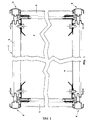
Figure 1 is a schematic plan view, partially in section, taken along a horizontal plane; -
Figure 2 illustrates a part ofFigure 1 in enlarged scale; -
Figure 3 is an exploded view ofFigure 2 ; -
Figure 4 is a side view ofFigure 2 , partially in section along the tracing plane I-I; -
Figure 5 is the same view ofFigure 2 in a different configuration. - With reference to the above mentioned figures,
reference numeral 1 indicates a vessel or containing element as a whole, used as a shelf in a shelving structure of the type used to obtain the inner fitting of outfitted commercial vans. The shelving structure being examined includes a plurality of containing elements orvessels 1, which are situated at prefixed distances one from another in vertical direction. Eachvessel 1 is provided, in its lower part, with abottom wall 2, from which rise externally afront wall 3, aback wall 4 and twoopposite side walls 5. - The
vessels 1, that form said plurality, are identical to one another and integrally fastened to supportuprights 6 at different heights. In this case, there are foursupport uprights 6, situated at four corners of thevessels 1. - Each
front wall 3 is formed by a piece of section member made of light alloy (of aluminium) and has its opposite ends formed so as to defineend contact surfaces 30, parallel to one another and aimed at contacting corresponding portions of surfaces of theopposite side walls 5 and support uprights 6 (at least for the front wall 3) of the shelving structure. - For each of said opposite ends of each front side 3 (and rear side 4), the connection between the
vessel 1 and its support upright 6 is made by a connectingbracket 7, in which two portions can be defined and arranged on two different planes. A first,outer portion 7a is aimed at being placed outside of thelateral wall 5 so as to interact at least with the portion of the support upright 6 facing and contacting a portion of thecontact surface 30 of the relative end of thefront wall 3. - A second,
inner portion 7b aimed at being placed inside thelateral wall 5 in an area, in which the outer side of this wall faces a portion of the outer surface of the support upright 6. - An intermediate folded
part 7c of a connectingbracket 7, made of elastically deformable material, is aimed at being freely introduced in aslot 50 made in eachlateral wall 5. Theintermediate part 7c connects the first,outer portion 7a, with the second,inner portion 7b. - Suitable means are provided for firmly connecting the second,
inner portion 7b, to the respective support upright 6 andlateral wall 5. - Centring and containing means serve to maintain the first,
outer portion 7a in a prefixed position on theend contact surface 30. - More in particular, the second,
inner portion 7b, situated in more internal position with respect to thelateral wall 5, when in its natural configuration, i.e. not firmly fixed contacting thewall 5, has a position, which is not parallel to that of the first,outer portion 7a. Such position defines an inclination, by virtue of which the intersection of the two planes, defined by the first,outer portion 7a and the second,inner portion 7b, is situated, with respect to the foldedintermediate part 7c, in the half space containing the first,outer portion 7a. - The centring and containing means aimed at maintaining the first,
outer portion 7a in a prefixed position on theend contact surface 30, include at least agudgeon 31 having a widened head. According to the illustrated embodiment, twoparallel gudgeons 31 are provided, each of which is perpendicularly fastened to theend contact surface 30 and has such dimensions as to be perfectly received in aslot 70 made in the first,outer portion 7a. - Each
gudgeon 31 has a widenedhead 32 with dimensions for interacting with a part of the outer surface of the first,outer portion 7a situated at the edge of saidslot 70. The diameter of the widenedhead 32 is larger than the width of theslot 70. The width of the latter is greater than the diameter of theshank portion 33 of thegudgeon 31, which remains protruding from theend contact surface 30 after the introduction has been completed. Theshank portion 33 of thegudgeon 31 is longer than the sum of the thicknesses of thelateral wall 5 and first,outer portion 7a. Theshank portion 33 is aimed at pushing firmly thelateral wall 5 against theend contact surface 30. Fastening is obtained by screwing the threadedportion 34 of thegudgeon 31, which screws into a suitable seat in thefront wall 3. - The two
gudgeons 5 are identical to each other, parallel and their axes lie in a common vertical plane. - The shape of each
slot 70 is elongated in horizontal direction. The twoslots 70 are identical to each other, as the respective gudgeons, and aligned in a vertical direction, parallel to the foldedintermediate wall 7c. - Each support upright 6 is made of a even square section member, which has, at each of two opposite sides an appendage or
fore wing 60, aimed at interacting in contact with a front part of thefore contact surface 30, and an appendage orrear wing 61, aimed at interacting in contact with a part of the outer surface of thelateral wall 5. The means for stable connection of the second,inner portion 7b to the respective support upright 6 and to thelateral wall 5, define a stable, tightly "packed" connection of each second,inner portion 7b with the correspondinglateral wall 5 and the correspondingrear wing 61 by means oftap bolts 8. - One of the ends 7d of the second,
inner portion 7b is folded so as to allow gripping in order to introduce and remove the connectingbracket 7. - During the assembly, the two
gudgeons 31, introduced in the twoslots 70, are screwed in suitable holes in correspondence to each of the surfaces of the portions of thewall 5 leaning on thecontact surfaces 30. - After the
fore wing 60 andrear wing 61 of the single support upright 6 have been moved closer to thelateral wall 5, the second,inner portion 7b is tightened and made adhere in matching contact to the inner surface of thelateral wall 5 by means oftap bolts 8. In order to simplify the operation, in the appendages orrear wings 61 there are rows ofsmall holes 62, in which thetap bolts 8 can be screwed easily and safely. - By contrast, due to the elastic deformability of the connecting
bracket 7, the first,outer portion 7a is pushed and kept in matching contact with the portion facing thewing 60 of the support upright 6. - This allows to set the structure at right angle.
- Those skilled in the art will understand that the present invention is not limited by what has been in particular illustrated and described previously, since the scope of the invention is defined by the following claims.
Claims (9)
- A shelving structure, of the type preferably used for inner fitting of outfitted commercial vans and comprising a plurality of containing elements or vessels (1), which are provided, in their lower part, with a bottom wall (2), along whose perimeter extend a front wall (3), a back wall (4) and two opposite side walls (5), said vessels (1) being integrally fastened to support uprights (6) at different heights characterized in that at least each said front wall (3) has opposite ends formed so as to define end contact surfaces (30) parallel to one another and aimed at contacting corresponding portions of surfaces of said opposite side walls (5) and of said support uprights (6); for each of said opposite ends, the connection between said vessel (1) and its support upright (6) being made by a connecting bracket (7), in which two portions can be defined and arranged on two different planes: a first outer portion (7a) aimed at being placed in outer position with respect to said lateral wall (5) so as to interact at least with the portion of said support upright (6) facing said contact surface (30) of the relative end of said front wall (3); a second inner portion (7b) aimed at being placed in internal position with respect to said lateral wall (5) in an area in which the outer side of this wall faces a portion of the outer surface of said support upright (6); each said lateral wall (5) having a slot (50), through which said connecting bracket (7) is aimed at being introduced freely at its folded intermediate part (7c), which connects said first outer portion (7a) with said second inner portion (7b); with means provided for stable connection of the second, inner portion (7b) to the relative support upright (6) and to said lateral wall (5) and centring and containing means aimed at maintaining said first, outer portion (7a) in a predetermined position on said end contact surface (30).
- A shelving structure according to claim 1, characterized in that said connecting bracket (7) is formed of a resiliently deformable material.
- A shelving structure according to claim 1, characterized in that said second, inner portion (7b), aimed at being situated inside said lateral wall (5), in its natural, not assembled configuration, lies in a position not parallel to that of the first, outer portion (7a), which defines an inclination, by virtue of which the intersection of the two planes, defined by the first, outer portion (7a) and the second, inner portion (7b), is situated, with respect to said folded intermediate wall (7c), in the half space containing the first, outer portion (7a).
- A shelving structure according to claim 1 or 3, characterized in that said centring and containing means aimed at maintaining said first, outer portion (7a) in a predetermined position on said end contact surface (30), include at least one gudgeon (31) with widened head, which is fastened perpendicularly to said end contact surface (30) and with such dimensions as to be received perfectly in a slot (70) made in said first, outer portion (7a).
- A shelving structure according to claim 4, characterized in that at least said gudgeon (31) has a widened head (32) with such dimension as to interact with a part of the outer surface of said first, outer portion (7a) situated at the edge of said slot (70).
- A shelving structure according to claim 4 or 5, characterized in that the shape of said slot (50) is elongated in horizontal direction.
- A shelving structure according to claim 5 or 6, characterized in that each said support upright (6) is formed by a section member having an even squared section, which features, at each of two opposite sides, an appendage or fore wing (60), aimed at interacting in contact with a front part of said fore contact surface (30), and an appendage or rear wing (61), aimed at interacting in contact with a part of said outer surface of the lateral wall (5).
- A shelving structure according to claim 7, characterized in that said means for stable connection of the second, inner portion (7b) to the respective support upright (6) and to said lateral wall (5), define a stable, tightly "packed" connection of each second, inner portion (7b) with the corresponding lateral wall (5) and the corresponding rear wing (61), which connection is made in form of a screw.
- A shelving structure according to any one of the previous claims, characterized in that the end (7b) of said second, inner portion (7b) is folded so as to allow gripping.
Applications Claiming Priority (1)
| Application Number | Priority Date | Filing Date | Title |
|---|---|---|---|
| IT000144A ITMO20120144A1 (en) | 2012-05-30 | 2012-05-30 | SHELF STRUCTURE IN PARTICULAR FOR THE INTERIOR PREPARATION OF EQUIPPED COMMERCIAL VANS |
Publications (2)
| Publication Number | Publication Date |
|---|---|
| EP2669533A1 true EP2669533A1 (en) | 2013-12-04 |
| EP2669533B1 EP2669533B1 (en) | 2015-01-07 |
Family
ID=46727385
Family Applications (1)
| Application Number | Title | Priority Date | Filing Date |
|---|---|---|---|
| EP20130002751 Active EP2669533B1 (en) | 2012-05-30 | 2013-05-28 | Shelving structure, in particular for inner fitting of commercial vans with facilities |
Country Status (2)
| Country | Link |
|---|---|
| EP (1) | EP2669533B1 (en) |
| IT (1) | ITMO20120144A1 (en) |
Citations (3)
| Publication number | Priority date | Publication date | Assignee | Title |
|---|---|---|---|---|
| FR2216760A5 (en) * | 1973-02-02 | 1974-08-30 | Inova Creations | |
| DE2803055A1 (en) * | 1975-05-02 | 1979-07-26 | Systemkonstruktion Produkt Ent | Corner connector for furniture or container - has fillet arc connected as extension of corner sections by adhesive or screws |
| WO2006027015A1 (en) * | 2004-09-10 | 2006-03-16 | Tegometall (International) Ag | Column comprising an adapter rail |
-
2012
- 2012-05-30 IT IT000144A patent/ITMO20120144A1/en unknown
-
2013
- 2013-05-28 EP EP20130002751 patent/EP2669533B1/en active Active
Patent Citations (3)
| Publication number | Priority date | Publication date | Assignee | Title |
|---|---|---|---|---|
| FR2216760A5 (en) * | 1973-02-02 | 1974-08-30 | Inova Creations | |
| DE2803055A1 (en) * | 1975-05-02 | 1979-07-26 | Systemkonstruktion Produkt Ent | Corner connector for furniture or container - has fillet arc connected as extension of corner sections by adhesive or screws |
| WO2006027015A1 (en) * | 2004-09-10 | 2006-03-16 | Tegometall (International) Ag | Column comprising an adapter rail |
Also Published As
| Publication number | Publication date |
|---|---|
| ITMO20120144A1 (en) | 2013-12-01 |
| EP2669533B1 (en) | 2015-01-07 |
Similar Documents
| Publication | Publication Date | Title |
|---|---|---|
| US9878649B2 (en) | High density foldaway shelving | |
| US9132784B2 (en) | Truck headache rack | |
| US10913398B2 (en) | Shelving systems | |
| US8901438B2 (en) | Electronic equipment cabinet structure | |
| EP3750444B1 (en) | Foldable shelving construction | |
| CN105307935B (en) | Seat unit | |
| US20080309107A1 (en) | Frame for building a vehicular body with a load bearing support system | |
| EP2842808A1 (en) | Mounting assembly for mounting a detachable article to an utility vehicle | |
| EP3287379B1 (en) | Double-surface contact tray loading base | |
| EP3694778B1 (en) | Two-piece center frame assembly | |
| WO2015123703A2 (en) | Stowable floor assembly for package delivery vehicles | |
| US9163778B2 (en) | Horizontal logistics bar holder for logistics trailers | |
| CN113978323A (en) | Seat attachment system for public transport vehicles | |
| EP1876875A2 (en) | Modular rack design | |
| US11147396B2 (en) | Display shelf system | |
| EP2669533B1 (en) | Shelving structure, in particular for inner fitting of commercial vans with facilities | |
| US10518710B2 (en) | Mounting bracket for console background | |
| US20240416822A1 (en) | Systems and methods for adjustable mobile storage for vehicle cargo | |
| AU2007100978A4 (en) | A shelving assembly for vehicles | |
| EP4126596B1 (en) | A driver's cabin of a vehicle | |
| US8813978B2 (en) | Material supporting ledge | |
| US12499786B2 (en) | Placard mounting structure | |
| US20070294975A1 (en) | Support panel for removable brackets and the like | |
| US20190031078A1 (en) | Load Bearing Rail and Tie-Down Ring Assembly | |
| JP6900215B2 (en) | Assist grip and luggage rack with it |
Legal Events
| Date | Code | Title | Description |
|---|---|---|---|
| PUAI | Public reference made under article 153(3) epc to a published international application that has entered the european phase |
Free format text: ORIGINAL CODE: 0009012 |
|
| 17P | Request for examination filed |
Effective date: 20130529 |
|
| AK | Designated contracting states |
Kind code of ref document: A1 Designated state(s): AL AT BE BG CH CY CZ DE DK EE ES FI FR GB GR HR HU IE IS IT LI LT LU LV MC MK MT NL NO PL PT RO RS SE SI SK SM TR |
|
| AX | Request for extension of the european patent |
Extension state: BA ME |
|
| REG | Reference to a national code |
Ref country code: DE Ref legal event code: R079 Ref document number: 602013000757 Country of ref document: DE Free format text: PREVIOUS MAIN CLASS: F16B0012500000 Ipc: A47B0057180000 |
|
| GRAP | Despatch of communication of intention to grant a patent |
Free format text: ORIGINAL CODE: EPIDOSNIGR1 |
|
| RIC1 | Information provided on ipc code assigned before grant |
Ipc: F16B 12/50 20060101ALN20140721BHEP Ipc: F16B 12/46 20060101ALN20140721BHEP Ipc: A47B 57/18 20060101AFI20140721BHEP |
|
| INTG | Intention to grant announced |
Effective date: 20140805 |
|
| GRAS | Grant fee paid |
Free format text: ORIGINAL CODE: EPIDOSNIGR3 |
|
| GRAA | (expected) grant |
Free format text: ORIGINAL CODE: 0009210 |
|
| AK | Designated contracting states |
Kind code of ref document: B1 Designated state(s): AL AT BE BG CH CY CZ DE DK EE ES FI FR GB GR HR HU IE IS IT LI LT LU LV MC MK MT NL NO PL PT RO RS SE SI SK SM TR |
|
| REG | Reference to a national code |
Ref country code: GB Ref legal event code: FG4D |
|
| REG | Reference to a national code |
Ref country code: CH Ref legal event code: EP |
|
| REG | Reference to a national code |
Ref country code: IE Ref legal event code: FG4D |
|
| REG | Reference to a national code |
Ref country code: AT Ref legal event code: REF Ref document number: 705067 Country of ref document: AT Kind code of ref document: T Effective date: 20150215 |
|
| REG | Reference to a national code |
Ref country code: DE Ref legal event code: R096 Ref document number: 602013000757 Country of ref document: DE Effective date: 20150219 |
|
| REG | Reference to a national code |
Ref country code: DE Ref legal event code: R082 Ref document number: 602013000757 Country of ref document: DE Representative=s name: PATENTANWAELTE WEICKMANN & WEICKMANN, DE Ref country code: DE Ref legal event code: R082 Ref document number: 602013000757 Country of ref document: DE Representative=s name: WEICKMANN & WEICKMANN PATENTANWAELTE - RECHTSA, DE Ref country code: DE Ref legal event code: R082 Ref document number: 602013000757 Country of ref document: DE Representative=s name: WEICKMANN & WEICKMANN PATENT- UND RECHTSANWAEL, DE |
|
| REG | Reference to a national code |
Ref country code: NL Ref legal event code: VDEP Effective date: 20150107 |
|
| REG | Reference to a national code |
Ref country code: AT Ref legal event code: MK05 Ref document number: 705067 Country of ref document: AT Kind code of ref document: T Effective date: 20150107 |
|
| REG | Reference to a national code |
Ref country code: LT Ref legal event code: MG4D |
|
| PG25 | Lapsed in a contracting state [announced via postgrant information from national office to epo] |
Ref country code: NO Free format text: LAPSE BECAUSE OF FAILURE TO SUBMIT A TRANSLATION OF THE DESCRIPTION OR TO PAY THE FEE WITHIN THE PRESCRIBED TIME-LIMIT Effective date: 20150407 Ref country code: SE Free format text: LAPSE BECAUSE OF FAILURE TO SUBMIT A TRANSLATION OF THE DESCRIPTION OR TO PAY THE FEE WITHIN THE PRESCRIBED TIME-LIMIT Effective date: 20150107 Ref country code: FI Free format text: LAPSE BECAUSE OF FAILURE TO SUBMIT A TRANSLATION OF THE DESCRIPTION OR TO PAY THE FEE WITHIN THE PRESCRIBED TIME-LIMIT Effective date: 20150107 Ref country code: BG Free format text: LAPSE BECAUSE OF FAILURE TO SUBMIT A TRANSLATION OF THE DESCRIPTION OR TO PAY THE FEE WITHIN THE PRESCRIBED TIME-LIMIT Effective date: 20150407 Ref country code: LT Free format text: LAPSE BECAUSE OF FAILURE TO SUBMIT A TRANSLATION OF THE DESCRIPTION OR TO PAY THE FEE WITHIN THE PRESCRIBED TIME-LIMIT Effective date: 20150107 Ref country code: ES Free format text: LAPSE BECAUSE OF FAILURE TO SUBMIT A TRANSLATION OF THE DESCRIPTION OR TO PAY THE FEE WITHIN THE PRESCRIBED TIME-LIMIT Effective date: 20150107 Ref country code: HR Free format text: LAPSE BECAUSE OF FAILURE TO SUBMIT A TRANSLATION OF THE DESCRIPTION OR TO PAY THE FEE WITHIN THE PRESCRIBED TIME-LIMIT Effective date: 20150107 |
|
| PG25 | Lapsed in a contracting state [announced via postgrant information from national office to epo] |
Ref country code: LV Free format text: LAPSE BECAUSE OF FAILURE TO SUBMIT A TRANSLATION OF THE DESCRIPTION OR TO PAY THE FEE WITHIN THE PRESCRIBED TIME-LIMIT Effective date: 20150107 Ref country code: RS Free format text: LAPSE BECAUSE OF FAILURE TO SUBMIT A TRANSLATION OF THE DESCRIPTION OR TO PAY THE FEE WITHIN THE PRESCRIBED TIME-LIMIT Effective date: 20150107 Ref country code: PL Free format text: LAPSE BECAUSE OF FAILURE TO SUBMIT A TRANSLATION OF THE DESCRIPTION OR TO PAY THE FEE WITHIN THE PRESCRIBED TIME-LIMIT Effective date: 20150107 Ref country code: NL Free format text: LAPSE BECAUSE OF FAILURE TO SUBMIT A TRANSLATION OF THE DESCRIPTION OR TO PAY THE FEE WITHIN THE PRESCRIBED TIME-LIMIT Effective date: 20150107 Ref country code: IS Free format text: LAPSE BECAUSE OF FAILURE TO SUBMIT A TRANSLATION OF THE DESCRIPTION OR TO PAY THE FEE WITHIN THE PRESCRIBED TIME-LIMIT Effective date: 20150507 Ref country code: GR Free format text: LAPSE BECAUSE OF FAILURE TO SUBMIT A TRANSLATION OF THE DESCRIPTION OR TO PAY THE FEE WITHIN THE PRESCRIBED TIME-LIMIT Effective date: 20150408 Ref country code: AT Free format text: LAPSE BECAUSE OF FAILURE TO SUBMIT A TRANSLATION OF THE DESCRIPTION OR TO PAY THE FEE WITHIN THE PRESCRIBED TIME-LIMIT Effective date: 20150107 |
|
| REG | Reference to a national code |
Ref country code: DE Ref legal event code: R097 Ref document number: 602013000757 Country of ref document: DE |
|
| PG25 | Lapsed in a contracting state [announced via postgrant information from national office to epo] |
Ref country code: SK Free format text: LAPSE BECAUSE OF FAILURE TO SUBMIT A TRANSLATION OF THE DESCRIPTION OR TO PAY THE FEE WITHIN THE PRESCRIBED TIME-LIMIT Effective date: 20150107 Ref country code: CZ Free format text: LAPSE BECAUSE OF FAILURE TO SUBMIT A TRANSLATION OF THE DESCRIPTION OR TO PAY THE FEE WITHIN THE PRESCRIBED TIME-LIMIT Effective date: 20150107 Ref country code: EE Free format text: LAPSE BECAUSE OF FAILURE TO SUBMIT A TRANSLATION OF THE DESCRIPTION OR TO PAY THE FEE WITHIN THE PRESCRIBED TIME-LIMIT Effective date: 20150107 Ref country code: RO Free format text: LAPSE BECAUSE OF FAILURE TO SUBMIT A TRANSLATION OF THE DESCRIPTION OR TO PAY THE FEE WITHIN THE PRESCRIBED TIME-LIMIT Effective date: 20150107 Ref country code: DK Free format text: LAPSE BECAUSE OF FAILURE TO SUBMIT A TRANSLATION OF THE DESCRIPTION OR TO PAY THE FEE WITHIN THE PRESCRIBED TIME-LIMIT Effective date: 20150107 |
|
| PLBE | No opposition filed within time limit |
Free format text: ORIGINAL CODE: 0009261 |
|
| STAA | Information on the status of an ep patent application or granted ep patent |
Free format text: STATUS: NO OPPOSITION FILED WITHIN TIME LIMIT |
|
| 26N | No opposition filed |
Effective date: 20151008 |
|
| PG25 | Lapsed in a contracting state [announced via postgrant information from national office to epo] |
Ref country code: LU Free format text: LAPSE BECAUSE OF FAILURE TO SUBMIT A TRANSLATION OF THE DESCRIPTION OR TO PAY THE FEE WITHIN THE PRESCRIBED TIME-LIMIT Effective date: 20150528 Ref country code: MC Free format text: LAPSE BECAUSE OF FAILURE TO SUBMIT A TRANSLATION OF THE DESCRIPTION OR TO PAY THE FEE WITHIN THE PRESCRIBED TIME-LIMIT Effective date: 20150107 |
|
| REG | Reference to a national code |
Ref country code: IE Ref legal event code: MM4A |
|
| PG25 | Lapsed in a contracting state [announced via postgrant information from national office to epo] |
Ref country code: SI Free format text: LAPSE BECAUSE OF FAILURE TO SUBMIT A TRANSLATION OF THE DESCRIPTION OR TO PAY THE FEE WITHIN THE PRESCRIBED TIME-LIMIT Effective date: 20150107 |
|
| PG25 | Lapsed in a contracting state [announced via postgrant information from national office to epo] |
Ref country code: IE Free format text: LAPSE BECAUSE OF NON-PAYMENT OF DUE FEES Effective date: 20150528 |
|
| PG25 | Lapsed in a contracting state [announced via postgrant information from national office to epo] |
Ref country code: BE Free format text: LAPSE BECAUSE OF FAILURE TO SUBMIT A TRANSLATION OF THE DESCRIPTION OR TO PAY THE FEE WITHIN THE PRESCRIBED TIME-LIMIT Effective date: 20150107 |
|
| REG | Reference to a national code |
Ref country code: FR Ref legal event code: PLFP Year of fee payment: 4 |
|
| PG25 | Lapsed in a contracting state [announced via postgrant information from national office to epo] |
Ref country code: MT Free format text: LAPSE BECAUSE OF FAILURE TO SUBMIT A TRANSLATION OF THE DESCRIPTION OR TO PAY THE FEE WITHIN THE PRESCRIBED TIME-LIMIT Effective date: 20150107 |
|
| REG | Reference to a national code |
Ref country code: CH Ref legal event code: PL |
|
| PG25 | Lapsed in a contracting state [announced via postgrant information from national office to epo] |
Ref country code: CH Free format text: LAPSE BECAUSE OF NON-PAYMENT OF DUE FEES Effective date: 20160531 Ref country code: LI Free format text: LAPSE BECAUSE OF NON-PAYMENT OF DUE FEES Effective date: 20160531 |
|
| REG | Reference to a national code |
Ref country code: FR Ref legal event code: PLFP Year of fee payment: 5 |
|
| PG25 | Lapsed in a contracting state [announced via postgrant information from national office to epo] |
Ref country code: HU Free format text: LAPSE BECAUSE OF FAILURE TO SUBMIT A TRANSLATION OF THE DESCRIPTION OR TO PAY THE FEE WITHIN THE PRESCRIBED TIME-LIMIT; INVALID AB INITIO Effective date: 20130528 |
|
| PG25 | Lapsed in a contracting state [announced via postgrant information from national office to epo] |
Ref country code: CY Free format text: LAPSE BECAUSE OF FAILURE TO SUBMIT A TRANSLATION OF THE DESCRIPTION OR TO PAY THE FEE WITHIN THE PRESCRIBED TIME-LIMIT Effective date: 20150107 |
|
| PG25 | Lapsed in a contracting state [announced via postgrant information from national office to epo] |
Ref country code: TR Free format text: LAPSE BECAUSE OF FAILURE TO SUBMIT A TRANSLATION OF THE DESCRIPTION OR TO PAY THE FEE WITHIN THE PRESCRIBED TIME-LIMIT Effective date: 20150107 |
|
| REG | Reference to a national code |
Ref country code: FR Ref legal event code: PLFP Year of fee payment: 6 |
|
| PG25 | Lapsed in a contracting state [announced via postgrant information from national office to epo] |
Ref country code: SM Free format text: LAPSE BECAUSE OF FAILURE TO SUBMIT A TRANSLATION OF THE DESCRIPTION OR TO PAY THE FEE WITHIN THE PRESCRIBED TIME-LIMIT Effective date: 20150107 |
|
| PG25 | Lapsed in a contracting state [announced via postgrant information from national office to epo] |
Ref country code: MK Free format text: LAPSE BECAUSE OF FAILURE TO SUBMIT A TRANSLATION OF THE DESCRIPTION OR TO PAY THE FEE WITHIN THE PRESCRIBED TIME-LIMIT Effective date: 20150107 Ref country code: PT Free format text: LAPSE BECAUSE OF FAILURE TO SUBMIT A TRANSLATION OF THE DESCRIPTION OR TO PAY THE FEE WITHIN THE PRESCRIBED TIME-LIMIT Effective date: 20150107 |
|
| PG25 | Lapsed in a contracting state [announced via postgrant information from national office to epo] |
Ref country code: AL Free format text: LAPSE BECAUSE OF FAILURE TO SUBMIT A TRANSLATION OF THE DESCRIPTION OR TO PAY THE FEE WITHIN THE PRESCRIBED TIME-LIMIT Effective date: 20150107 |
|
| P01 | Opt-out of the competence of the unified patent court (upc) registered |
Effective date: 20230328 |
|
| PGFP | Annual fee paid to national office [announced via postgrant information from national office to epo] |
Ref country code: DE Payment date: 20250626 Year of fee payment: 13 |
|
| PGFP | Annual fee paid to national office [announced via postgrant information from national office to epo] |
Ref country code: GB Payment date: 20250623 Year of fee payment: 13 |
|
| PGFP | Annual fee paid to national office [announced via postgrant information from national office to epo] |
Ref country code: IT Payment date: 20250530 Year of fee payment: 13 |
|
| PGFP | Annual fee paid to national office [announced via postgrant information from national office to epo] |
Ref country code: FR Payment date: 20250530 Year of fee payment: 13 |