EP2669500A2 - Jet exhaust noise reduction - Google Patents
Jet exhaust noise reduction Download PDFInfo
- Publication number
- EP2669500A2 EP2669500A2 EP13165089.7A EP13165089A EP2669500A2 EP 2669500 A2 EP2669500 A2 EP 2669500A2 EP 13165089 A EP13165089 A EP 13165089A EP 2669500 A2 EP2669500 A2 EP 2669500A2
- Authority
- EP
- European Patent Office
- Prior art keywords
- exhaust gas
- nozzle
- exhaust
- streamtube
- jet
- Prior art date
- Legal status (The legal status is an assumption and is not a legal conclusion. Google has not performed a legal analysis and makes no representation as to the accuracy of the status listed.)
- Granted
Links
Images


Classifications
-
- F—MECHANICAL ENGINEERING; LIGHTING; HEATING; WEAPONS; BLASTING
- F02—COMBUSTION ENGINES; HOT-GAS OR COMBUSTION-PRODUCT ENGINE PLANTS
- F02K—JET-PROPULSION PLANTS
- F02K1/00—Plants characterised by the form or arrangement of the jet pipe or nozzle; Jet pipes or nozzles peculiar thereto
- F02K1/28—Plants characterised by the form or arrangement of the jet pipe or nozzle; Jet pipes or nozzles peculiar thereto using fluid jets to influence the jet flow
- F02K1/34—Plants characterised by the form or arrangement of the jet pipe or nozzle; Jet pipes or nozzles peculiar thereto using fluid jets to influence the jet flow for attenuating noise
-
- F—MECHANICAL ENGINEERING; LIGHTING; HEATING; WEAPONS; BLASTING
- F02—COMBUSTION ENGINES; HOT-GAS OR COMBUSTION-PRODUCT ENGINE PLANTS
- F02K—JET-PROPULSION PLANTS
- F02K1/00—Plants characterised by the form or arrangement of the jet pipe or nozzle; Jet pipes or nozzles peculiar thereto
- F02K1/38—Introducing air inside the jet
- F02K1/383—Introducing air inside the jet with retractable elements
Definitions
- This application relates generally to a method and device for reducing noise generated by supersonic jet exhaust.
- a supersonic jet exhaust nozzle generally includes an upstream converging section and a downstream diverging section.
- the converging section expands and accelerates subsonic exhaust gas flow such that the exhaust gas flow reaches the speed of sound at a location of minimum cross-sectional area known as the geometric throat of the nozzle.
- the diverging section of the nozzle which begins downstream from the throat, further expands and accelerates the exhaust gas flow to supersonic speeds.
- the Mach cones are formed as the plume undergoes pressure equalization with the ambient air. Mach cones created in the jet exhaust are propagated downstream along the jet exhaust plume.
- the Mach cones include shock waves, which generate a significant amount of noise as they impinge upon the shear layer between the exhaust plume and the ambient air.
- the amount of noise generated by a jet engine's exhaust plume may, therefore, vary according to (among other factors) an expansion state of an engine's exhaust nozzle, which governs the exhaust plume's pressure relative to that of the ambient air mass.
- a jet engine exhaust nozzle may have an ideally expanded, under-expanded, or over-expanded state.
- An under-expanded nozzle is a nozzle shaped such that jet engine exhaust gas pressure at a nozzle exit plane is higher than ambient atmospheric pressure.
- an over-expanded nozzle is a nozzle shaped such that jet engine exhaust gas pressure at the nozzle exit plane is lower than ambient atmospheric pressure.
- a perfectly or ideally expanded nozzle is a nozzle shaped in such a way that jet engine exhaust gas pressure at the nozzle exit plane equals ambient atmospheric pressure, thereby precluding the formation of Mach cones.
- a method for reducing jet noise by weakening Mach cones in a jet exhaust gas streamtube is provided.
- the Mach cones are weakened by modifying exhaust gas flow in a longitudinal axial core of the exhaust gas streamtube.
- jet noise reduction device comprising a gas flow modifier, at least a portion of which is deployable along a central longitudinal axis of a jet exhaust nozzle.
- the gas flow modifier is configured to weaken jet exhaust streamtube Mach cones by modifying gas flow along a longitudinal axial core of the jet exhaust gas streamtube.
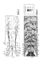
- Figure 1 is a schematic cross-sectional side view of a jet exhaust gas stream exiting a jet exhaust nozzle and forming an exhaust plume and showing Mach cones being generated in a diverging, supersonic section of the nozzle and propagating downstream in the exhaust plume;
- Figure 2 is a pressure gradient map of the jet exhaust gas stream and nozzle of Figure 1 ;
- Figure 3 is a schematic cross-sectional side view of an illustrative embodiment of a jet exhaust noise reduction device in the form of a virtual plug comprising a porous tube emitting pressurized air into the diverging section of a nozzle along a longitudinal axial core of the exhaust gas stream;
- Figure 4 is a pressure gradient map of the jet exhaust gas stream and nozzle of Figure 3 ;
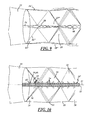
- Figure 5 is a schematic cross-sectional side view of another illustrative embodiment of a jet exhaust noise reduction device in the form of a porous tube transpiration element deployed along a longitudinal axial core of a jet exhaust gas stream;
- Figure 6 is a pressure gradient map of the jet exhaust gas stream and nozzle of Figure 5 ;
- Figure 7 is a schematic cross-sectional side view of an additional illustrative embodiment of a jet exhaust noise reduction device in the form of a secondary subjet disposed in a diverging section of a jet exhaust nozzle and directing a high energy flow of gas along a centerline of an exhaust gas plume;
- Figure 8 is a pressure gradient map of the jet exhaust gas stream and nozzle of Figure 7 ;
- Figure 9 is a schematic magnified view of region 9 of Figure 7 depicting interaction between the jet exhaust gas stream and the high energy flow from the secondary subjet;
- Figure 10 is a schematic magnified view depicting interaction between the jet exhaust gas stream of Figure 5 and transpiration flow into and out of the porous tube of Figure 5 ;
- Figure 11 is a cutaway view of the jet exhaust noise reduction device of Figure 5 installed in a turbine hub cone of a jet engine at an upstream end of an exhaust nozzle of the engine and shown with the porous tube transpiration element retracted onto a reel of the device within the turbine hub;
- Figure 12 is a magnified cutaway view of the retracted porous tube transpiration element of Figure 11 ;
- Figure 13 is a cutaway view of the jet engine exhaust noise reduction device of Figures 5 , 11, and 12 shown with the porous tube transpiration element deployed from the reel through an opening in an apex of the turbine hub cone;
- Figure 14 is a magnified cutaway view of the deployed porous tube transpiration element of Figure 13 .
- FIG. 10 Generally indicated at 10 in Figures 3 and 4 is a device that reduces supersonic noise generated when Mach cone shock waves in a j et exhaust plume impinge upon a shear layer surrounding the exhaust plume.
- a second embodiment is generally indicated at 10' in Figures 5, 6 , and 10-14
- a third embodiment is generally indicated at 10" in Figures 7-9 .
- Reference numerals with the designation prime (') or double prime (") indicate alternative configurations of elements that also appear in other embodiments. Unless indicated otherwise, where a portion of the following description uses a reference numeral to refer to Figures 3 and 4 , that portion of the description applies equally to elements designated by primed or double primed numerals in other Figures.
- the device 10 may include a gas flow modifier 12 that may be disposed in a longitudinal axial core region 13 of a jet exhaust gas streamtube 14.
- the gas flow modifier 12 may be positioned and configured to modify gas flow along the longitudinal axial core region 13 of the streamtube 14 in such a way as to weaken Mach cones 16 that are formed in a supersonic portion of the exhaust gas streamtube 14 as shown in Figures 1-4 . Weakening of the Mach cones 16 reduces the amount of noise generated by the Mach cones 16 as they impinge upon an exhaust plume shear layer 18 surrounding an exhaust plume 20.
- exhaust gas streamtube herein refers to a flow of exhaust gas through a jet exhaust nozzle 22 and into an exhaust plume 20 formed where streamtube exhaust gases exit the nozzle 22.
- Figures 1 and 2 show baseline visual and pressure images, respectively, of such an exhaust gas streamtube 14 exiting a jet exhaust nozzle 22 with no gas flow modifier 12 present.
- the exhaust gas flow modifier 12 may include a transpiration element 24 that may be deployed along a central longitudinal axis 27 of the jet exhaust nozzle 22 such that the element 24 passes through at least respective portions of both converging 30 and diverging 28 sections of the nozzle 22.
- the transpiration element 24 may be configured to passively absorb exhaust gas from the streamtube 14 where the streamtube 14 passes through the relatively high-pressure converging section 30 of the nozzle 22 and may be further configured to expel the absorbed exhaust gas back into the streamtube 14 where the streamtube 14 passes through the relatively low-pressure diverging section 28 of the nozzle 22.
- the transpiration element 24 may comprise a flexible porous tube 26 that may absorb exhaust gas from the streamtube 14 through upstream pores 32 in the nozzle's converging section 30 and expel the absorbed exhaust gas back into the streamtube 14 via downstream pores 34 in the nozzle's diverging section 28.
- low energy air could be routed into the tube 26 from another low energy air source 29 and forced through the downstream pores 34 of the porous tube 26. According to this alternative arrangement there would be no need for upstream pores 32 in the flexible porous tube 26.
- the flexible porous tube 26 may thus act as a "virtual plug” by expelling exhaust gas out of downstream pores 34 in such a way as to form a low energy wake 36 (In other words, having lower stagnation pressure than the surrounding exhaust plume 20) that displaces an axial core of the exhaust gas streamtube 14 such that the exhaust gas streamtube 14 becomes annular in shape where the exhaust gas streamtube 14 crosses an exit plane 38 of the exhaust nozzle 22.
- the tube 26 may be configured to expel air from its downstream pores 34 in such a way as to form a wake 36 that forms the exhaust gas streamtube 14 into an annular cross-sectional shape having, at the nozzle exit plane 38, a lowered effective cross-sectional exit area that approaches an ideal expansion state, i.e., a cross-sectional exit area close enough to an ideal expansion state to weaken Mach cones sufficiently to effect a noise level reduction of a desired magnitude.
- the flexible porous tube 26 may comprise Sylramic TM SiC Fiber or any other suitable flexible material capable of withstanding high temperatures.
- the tube 26 may comprise any suitable non-flexible heat-resistant material formed in interconnected segments that allow the tube to flex.
- an exhaust gas flow modifier 12' may alternatively include a Mach cone silencer 39 comprising a longer transpiration element 40 (i.e., a transpiration element 40 longer than the transpiration element 24 of the first embodiment) that is deployable along a longitudinal axial core 13' of an exhaust gas streamtube 14'.
- a longer transpiration element 40 i.e., a transpiration element 40 longer than the transpiration element 24 of the first embodiment
- the long transpiration element 40 may be configured to extend through and past the nozzle exit plane 38 to passively weaken Mach cones 16' in the exhaust plume 20' by reducing pressure differentials across (i.e., between opposite sides of) Mach cone shock waves 16.
- the reduced pressure differentials cause a corresponding reduction in magnitude of the impingement of the exhaust plume Mach cones 16 on the shear layer 18 surrounding the jet exhaust plume 20'.
- the long transpiration element 40 may passively absorb and expel gas in a way that mimics a wavy rod configured to weaken the reflected strength of any incident wave (compression or expansion), thereby weakening the exhaust plume Mach cones 16'.
- This embodiment may be employed to reduce noise in either under-expanded or over-expanded jet plumes.
- the long transpiration element 40 may comprise a long flexible porous tube 42 (i.e., a flexible porous tube 42 longer than the flexible porous tube 26 of the first embodiment) deployable along the longitudinal axial core 13' of the exhaust gas streamtube 14'.
- a long porous tube 42 plume exhaust gases may be drawn into the long porous tube 42 through tube pores 52 disposed in relatively high pressure portions 53 of Mach cone shock waves 16'. The gases may be exhausted from the long porous tube through tube pores 54 disposed in relatively low pressure portions 55 of Mach cone shock waves 16'.
- the device 10' may include a reel 44 that may be disposed in an engine turbine hub cone 46 and may be configured to deploy and retract the long porous tube 42 through an opening 48 at an apex of the turbine hub cone 46. As best shown in Figures 5, 6 , and 13 , the device 10' may be configured to deploy the porous tube 42 to preferably extend approximately 3 (between 2.5 and 4) nozzle diameters aft of the nozzle exit plane 38.
- the exhaust gas flow modifier 12" may include a Mach cone silencer 39" in the form of a secondary subjet 56 rather than a porous tube.
- the secondary subjet 56 may be configured and positioned to emit a high-energy (stagnation pressure greater than the surrounding exhaust plume 20") supersonic secondary gas plume 58 into a diverging section 28 of the jet exhaust nozzle 22 along the longitudinal axial core 13" of the exhaust gas streamtube 14".
- secondary Mach cones 60 formed in the secondary gas plume 58 weaken the Mach cones 16" of the surrounding (primary) exhaust plume 20" and reduce noise due to impingement of the primary plume's Mach cones 16" on the shear layer 18" surrounding the primary plume 20".
- noise generated when Mach cone shock waves 16 in the supersonic flow region of the jet exhaust gas streamtube 14 impinge upon the shear layer 18 surrounding the plume portion of the streamtube 14, may be reduced by modifying exhaust gas flow in the longitudinal axial core region of the exhaust gas streamtube 14 in such a way as to weaken the Mach cones 16.
- exhaust plume Mach cones 16 may be passively weakened or inhibited during formation by deploying a gas flow modifier 12 in the form of a transpiration element 24, such as a flexible porous tube 26, to a position along the central longitudinal axis 27 of the exhaust nozzle 22 through which the exhaust gas is flowing.
- the transpiration element 24 may extend from a converging (subsonic) section 30 of the exhaust nozzle 22 into a diverging (supersonic) section 28 of the nozzle 22 and may be configured to passively absorb exhaust gases from the streamtube 14 in the converging section 30 of the nozzle 22 and expel the absorbed gasses into the diverging section 28 of the nozzle 22 upstream of the nozzle exit plane 38.
- the gases may be expelled from the transpiration element 24 such that a low energy wake 36 or "virtual plug” is generated along the longitudinal axial core 13 of the exhaust gas streamtube 14 in the diverging section 28 of the jet exhaust nozzle 22.
- the low energy wake 36 may be generated such that it displaces the axial core 13 of the exhaust gas streamtube 14, forcing the exhaust gas streamtube 14 into an annular cross-sectional configuration having a lowered effective cross-sectional area that approaches an ideal cross-sectional area for a perfectly expanded state where the exhaust gas streamtube 14 crosses the exit plane 38 of the exhaust nozzle 22.
- exhaust plume Mach cones 16' may be passively weakened by deploying a longer transpiration element 40, such as a long flexible porous tube 42 to preferably extend approximately 3 nozzle diameters aft of the nozzle exit plane 38 along the longitudinal axial core 13' of the exhaust gas streamtube 14'.
- the long transpiration element 40 may be configured to act as a "Mach cone silencer" while deployed, by reducing pressure differentials across Mach cone shock waves 16'.
- the transpiration element may be deployed while the jet engine is running and a jet exhaust plume 20' is present, and may be retracted before the jet is shut down so that the transpiration element is deployed only when supported by the exhaust gas streamtube 14'.
- exhaust plume Mach cones 16" may be weakened by a Mach Cone Silencer 39" in the form of a subjet 56, rather than a porous tube, disposed in the diverging section 28 of the jet exhaust nozzle 22.
- the subjet 56 may be positioned and configured to emit a high-energy flow of gas along a longitudinal axial core 13" of the exhaust gas streamtube 14" to form a narrow secondary supersonic plume 58 having subjet Mach cones 60 that weaken the primary exhaust plume Mach cones 16".
- a jet noise reduction device constructed and employed as described above greatly reduces noise generated by Mach cone formation in jet exhaust plumes, with negligible impact on an engine's thrust.
- an engine equipped with such a device can produce more thrust for a given amount of sound generated, than could the same engine without a sound reduction device.
- an aircraft equipped with noise reduction devices retains a better performance envelope than unmodified aircraft in areas with noise reduction restrictions.
- engines may also be designed to have a superior performance envelope that would otherwise produce an unacceptable level of noise.
Landscapes
- Engineering & Computer Science (AREA)
- Chemical & Material Sciences (AREA)
- Combustion & Propulsion (AREA)
- Mechanical Engineering (AREA)
- General Engineering & Computer Science (AREA)
- Exhaust Silencers (AREA)
Abstract
Description
- This application relates generally to a method and device for reducing noise generated by supersonic jet exhaust.
- A supersonic jet exhaust nozzle generally includes an upstream converging section and a downstream diverging section. The converging section expands and accelerates subsonic exhaust gas flow such that the exhaust gas flow reaches the speed of sound at a location of minimum cross-sectional area known as the geometric throat of the nozzle. The diverging section of the nozzle, which begins downstream from the throat, further expands and accelerates the exhaust gas flow to supersonic speeds.
- A difference in pressure between an ambient air mass and supersonic exhaust gases departing the nozzle at a nozzle exit, causes cone-shaped waves of compression and expansion, or "Mach cones," to form in an exhaust plume formed downstream from the nozzle exit. The Mach cones are formed as the plume undergoes pressure equalization with the ambient air. Mach cones created in the jet exhaust are propagated downstream along the jet exhaust plume. The Mach cones include shock waves, which generate a significant amount of noise as they impinge upon the shear layer between the exhaust plume and the ambient air.
- The amount of noise generated by a jet engine's exhaust plume may, therefore, vary according to (among other factors) an expansion state of an engine's exhaust nozzle, which governs the exhaust plume's pressure relative to that of the ambient air mass. A jet engine exhaust nozzle may have an ideally expanded, under-expanded, or over-expanded state. An under-expanded nozzle is a nozzle shaped such that jet engine exhaust gas pressure at a nozzle exit plane is higher than ambient atmospheric pressure. In contrast, an over-expanded nozzle is a nozzle shaped such that jet engine exhaust gas pressure at the nozzle exit plane is lower than ambient atmospheric pressure. A perfectly or ideally expanded nozzle is a nozzle shaped in such a way that jet engine exhaust gas pressure at the nozzle exit plane equals ambient atmospheric pressure, thereby precluding the formation of Mach cones.
- A method is provided for reducing jet noise by weakening Mach cones in a jet exhaust gas streamtube. The Mach cones are weakened by modifying exhaust gas flow in a longitudinal axial core of the exhaust gas streamtube.
- Also provided is jet noise reduction device comprising a gas flow modifier, at least a portion of which is deployable along a central longitudinal axis of a jet exhaust nozzle. The gas flow modifier is configured to weaken jet exhaust streamtube Mach cones by modifying gas flow along a longitudinal axial core of the jet exhaust gas streamtube.
- These and other features and advantages will become apparent to those skilled in the art in connection with the following detailed description and drawings of one or more embodiments of the invention, in which:
-
Figure 1 is a schematic cross-sectional side view of a jet exhaust gas stream exiting a jet exhaust nozzle and forming an exhaust plume and showing Mach cones being generated in a diverging, supersonic section of the nozzle and propagating downstream in the exhaust plume; -
Figure 2 is a pressure gradient map of the jet exhaust gas stream and nozzle ofFigure 1 ; -
Figure 3 is a schematic cross-sectional side view of an illustrative embodiment of a jet exhaust noise reduction device in the form of a virtual plug comprising a porous tube emitting pressurized air into the diverging section of a nozzle along a longitudinal axial core of the exhaust gas stream; -
Figure 4 is a pressure gradient map of the jet exhaust gas stream and nozzle ofFigure 3 ; -
Figure 5 is a schematic cross-sectional side view of another illustrative embodiment of a jet exhaust noise reduction device in the form of a porous tube transpiration element deployed along a longitudinal axial core of a jet exhaust gas stream; -
Figure 6 is a pressure gradient map of the jet exhaust gas stream and nozzle ofFigure 5 ; -
Figure 7 is a schematic cross-sectional side view of an additional illustrative embodiment of a jet exhaust noise reduction device in the form of a secondary subjet disposed in a diverging section of a jet exhaust nozzle and directing a high energy flow of gas along a centerline of an exhaust gas plume; -
Figure 8 is a pressure gradient map of the jet exhaust gas stream and nozzle ofFigure 7 ; -
Figure 9 is a schematic magnified view of region 9 ofFigure 7 depicting interaction between the jet exhaust gas stream and the high energy flow from the secondary subjet; -
Figure 10 is a schematic magnified view depicting interaction between the jet exhaust gas stream ofFigure 5 and transpiration flow into and out of the porous tube ofFigure 5 ; -
Figure 11 is a cutaway view of the jet exhaust noise reduction device ofFigure 5 installed in a turbine hub cone of a jet engine at an upstream end of an exhaust nozzle of the engine and shown with the porous tube transpiration element retracted onto a reel of the device within the turbine hub; -
Figure 12 is a magnified cutaway view of the retracted porous tube transpiration element ofFigure 11 ; -
Figure 13 is a cutaway view of the jet engine exhaust noise reduction device ofFigures 5 ,11, and 12 shown with the porous tube transpiration element deployed from the reel through an opening in an apex of the turbine hub cone; and -
Figure 14 is a magnified cutaway view of the deployed porous tube transpiration element ofFigure 13 . - Generally indicated at 10 in
Figures 3 and 4 is a device that reduces supersonic noise generated when Mach cone shock waves in a j et exhaust plume impinge upon a shear layer surrounding the exhaust plume. A second embodiment is generally indicated at 10' inFigures 5, 6 , and10-14 , and a third embodiment is generally indicated at 10" inFigures 7-9 . Reference numerals with the designation prime (') or double prime (") indicate alternative configurations of elements that also appear in other embodiments. Unless indicated otherwise, where a portion of the following description uses a reference numeral to refer toFigures 3 and 4 , that portion of the description applies equally to elements designated by primed or double primed numerals in other Figures. - According to the first embodiment, the
device 10 may include agas flow modifier 12 that may be disposed in a longitudinalaxial core region 13 of a jetexhaust gas streamtube 14. As shown inFigures 3 and 4 , thegas flow modifier 12 may be positioned and configured to modify gas flow along the longitudinalaxial core region 13 of thestreamtube 14 in such a way as to weakenMach cones 16 that are formed in a supersonic portion of theexhaust gas streamtube 14 as shown inFigures 1-4 . Weakening of the Machcones 16 reduces the amount of noise generated by the Machcones 16 as they impinge upon an exhaustplume shear layer 18 surrounding anexhaust plume 20. - The term "exhaust gas streamtube" herein refers to a flow of exhaust gas through a
jet exhaust nozzle 22 and into anexhaust plume 20 formed where streamtube exhaust gases exit thenozzle 22.Figures 1 and 2 show baseline visual and pressure images, respectively, of such anexhaust gas streamtube 14 exiting ajet exhaust nozzle 22 with nogas flow modifier 12 present. - The exhaust
gas flow modifier 12 may include a transpiration element 24 that may be deployed along a centrallongitudinal axis 27 of thejet exhaust nozzle 22 such that the element 24 passes through at least respective portions of both converging 30 and diverging 28 sections of thenozzle 22. The transpiration element 24 may be configured to passively absorb exhaust gas from thestreamtube 14 where thestreamtube 14 passes through the relatively high-pressure converging section 30 of thenozzle 22 and may be further configured to expel the absorbed exhaust gas back into thestreamtube 14 where thestreamtube 14 passes through the relatively low-pressure diverging section 28 of thenozzle 22. - The transpiration element 24 may comprise a flexible
porous tube 26 that may absorb exhaust gas from thestreamtube 14 throughupstream pores 32 in the nozzle'sconverging section 30 and expel the absorbed exhaust gas back into thestreamtube 14 viadownstream pores 34 in the nozzle's divergingsection 28. Alternatively, low energy air could be routed into thetube 26 from another lowenergy air source 29 and forced through thedownstream pores 34 of theporous tube 26. According to this alternative arrangement there would be no need forupstream pores 32 in the flexibleporous tube 26. - In either case, the flexible
porous tube 26 may thus act as a "virtual plug" by expelling exhaust gas out ofdownstream pores 34 in such a way as to form a low energy wake 36 (In other words, having lower stagnation pressure than the surrounding exhaust plume 20) that displaces an axial core of theexhaust gas streamtube 14 such that theexhaust gas streamtube 14 becomes annular in shape where theexhaust gas streamtube 14 crosses anexit plane 38 of theexhaust nozzle 22. Where theexhaust nozzle 22 is over-expanded, thetube 26 may be configured to expel air from itsdownstream pores 34 in such a way as to form awake 36 that forms theexhaust gas streamtube 14 into an annular cross-sectional shape having, at thenozzle exit plane 38, a lowered effective cross-sectional exit area that approaches an ideal expansion state, i.e., a cross-sectional exit area close enough to an ideal expansion state to weaken Mach cones sufficiently to effect a noise level reduction of a desired magnitude. The flexibleporous tube 26 may comprise Sylramic ™ SiC Fiber or any other suitable flexible material capable of withstanding high temperatures. Alternatively, thetube 26 may comprise any suitable non-flexible heat-resistant material formed in interconnected segments that allow the tube to flex. - According to the second embodiment, and as shown in
Figures 5 and 6 , an exhaust gas flow modifier 12' may alternatively include a Machcone silencer 39 comprising a longer transpiration element 40 (i.e., a transpiration element 40 longer than the transpiration element 24 of the first embodiment) that is deployable along a longitudinal axial core 13' of an exhaust gas streamtube 14'. Where the relatively short transpiration element 24 of the first embodiment transpires gas only within the nozzle, the long transpiration element 40 may be configured to extend through and past thenozzle exit plane 38 to passively weaken Mach cones 16' in the exhaust plume 20' by reducing pressure differentials across (i.e., between opposite sides of) Machcone shock waves 16. The reduced pressure differentials cause a corresponding reduction in magnitude of the impingement of the exhaustplume Mach cones 16 on theshear layer 18 surrounding the jet exhaust plume 20'. In other words, the long transpiration element 40 may passively absorb and expel gas in a way that mimics a wavy rod configured to weaken the reflected strength of any incident wave (compression or expansion), thereby weakening the exhaust plume Mach cones 16'. This embodiment may be employed to reduce noise in either under-expanded or over-expanded jet plumes. - As best shown in
Figure 10 , the long transpiration element 40 may comprise a long flexible porous tube 42 (i.e., a flexibleporous tube 42 longer than the flexibleporous tube 26 of the first embodiment) deployable along the longitudinal axial core 13' of the exhaust gas streamtube 14'. Where the long transpiration element 40 is a longporous tube 42, plume exhaust gases may be drawn into the longporous tube 42 throughtube pores 52 disposed in relativelyhigh pressure portions 53 of Mach cone shock waves 16'. The gases may be exhausted from the long porous tube throughtube pores 54 disposed in relativelylow pressure portions 55 of Mach cone shock waves 16'. As shown inFigures 11-14 , the device 10' may include areel 44 that may be disposed in an engineturbine hub cone 46 and may be configured to deploy and retract the longporous tube 42 through anopening 48 at an apex of theturbine hub cone 46. As best shown inFigures 5, 6 , and13 , the device 10' may be configured to deploy theporous tube 42 to preferably extend approximately 3 (between 2.5 and 4) nozzle diameters aft of thenozzle exit plane 38. - According to the third embodiment, and as shown in
Figures 7-9 , the exhaustgas flow modifier 12" may include aMach cone silencer 39" in the form of asecondary subjet 56 rather than a porous tube. Thesecondary subjet 56 may be configured and positioned to emit a high-energy (stagnation pressure greater than the surroundingexhaust plume 20") supersonicsecondary gas plume 58 into a divergingsection 28 of thejet exhaust nozzle 22 along the longitudinalaxial core 13" of theexhaust gas streamtube 14". As best shown inFigure 9 ,secondary Mach cones 60 formed in thesecondary gas plume 58 weaken theMach cones 16" of the surrounding (primary)exhaust plume 20" and reduce noise due to impingement of the primary plume'sMach cones 16" on theshear layer 18" surrounding theprimary plume 20". - In practice, noise generated when Mach
cone shock waves 16 in the supersonic flow region of the jetexhaust gas streamtube 14 impinge upon theshear layer 18 surrounding the plume portion of thestreamtube 14, may be reduced by modifying exhaust gas flow in the longitudinal axial core region of theexhaust gas streamtube 14 in such a way as to weaken theMach cones 16. - As shown in
Figures 1 and 2 , exhaustplume Mach cones 16 may be passively weakened or inhibited during formation by deploying agas flow modifier 12 in the form of a transpiration element 24, such as a flexibleporous tube 26, to a position along the centrallongitudinal axis 27 of theexhaust nozzle 22 through which the exhaust gas is flowing. The transpiration element 24 may extend from a converging (subsonic)section 30 of theexhaust nozzle 22 into a diverging (supersonic)section 28 of thenozzle 22 and may be configured to passively absorb exhaust gases from thestreamtube 14 in the convergingsection 30 of thenozzle 22 and expel the absorbed gasses into the divergingsection 28 of thenozzle 22 upstream of thenozzle exit plane 38. The gases may be expelled from the transpiration element 24 such that alow energy wake 36 or "virtual plug" is generated along the longitudinalaxial core 13 of theexhaust gas streamtube 14 in the divergingsection 28 of thejet exhaust nozzle 22. Thelow energy wake 36 may be generated such that it displaces theaxial core 13 of theexhaust gas streamtube 14, forcing theexhaust gas streamtube 14 into an annular cross-sectional configuration having a lowered effective cross-sectional area that approaches an ideal cross-sectional area for a perfectly expanded state where theexhaust gas streamtube 14 crosses theexit plane 38 of theexhaust nozzle 22. - Alternatively, as shown in
Figures 5, 6 , and10-14 , exhaust plume Mach cones 16' may be passively weakened by deploying a longer transpiration element 40, such as a long flexibleporous tube 42 to preferably extend approximately 3 nozzle diameters aft of thenozzle exit plane 38 along the longitudinal axial core 13' of the exhaust gas streamtube 14'. The long transpiration element 40 may be configured to act as a "Mach cone silencer" while deployed, by reducing pressure differentials across Mach cone shock waves 16'. The transpiration element may be deployed while the jet engine is running and a jet exhaust plume 20' is present, and may be retracted before the jet is shut down so that the transpiration element is deployed only when supported by the exhaust gas streamtube 14'. - As a further alternative shown in
Figures 7-9 , exhaustplume Mach cones 16" may be weakened by aMach Cone Silencer 39" in the form of asubjet 56, rather than a porous tube, disposed in the divergingsection 28 of thejet exhaust nozzle 22. Thesubjet 56 may be positioned and configured to emit a high-energy flow of gas along a longitudinalaxial core 13" of theexhaust gas streamtube 14" to form a narrow secondarysupersonic plume 58 havingsubjet Mach cones 60 that weaken the primary exhaustplume Mach cones 16". - A jet noise reduction device constructed and employed as described above greatly reduces noise generated by Mach cone formation in jet exhaust plumes, with negligible impact on an engine's thrust. Among other advantages, an engine equipped with such a device can produce more thrust for a given amount of sound generated, than could the same engine without a sound reduction device. Thus, an aircraft equipped with noise reduction devices retains a better performance envelope than unmodified aircraft in areas with noise reduction restrictions. By using the presently disclosed device/method, engines may also be designed to have a superior performance envelope that would otherwise produce an unacceptable level of noise.
- This description, rather than describing limitations of an invention, only illustrates embodiments of the invention described in the claims. The language of this description is therefore exclusively descriptive and is non-limiting. Obviously, it's possible to modify this invention from what the description teaches. Within the scope of the claims, one may practice the invention other than as described above.
Claims (15)
- A method of reducing jet noise by weakening Mach cones (16;16';16") in a jet exhaust gas streamtube (14; 14'; 14") by modifying exhaust gas flow in a longitudinal axial core (13; 13'; 13") of the exhaust gas streamtube.
- The method of claim 1 in which the step of modifying exhaust gas flow includes generating a low energy wake (36) along the longitudinal axial core (13) of the exhaust gas streamtube (14) in a diverging section (28) of the jet exhaust nozzle (22) such that the low energy wake displaces the axial core of the exhaust gas streamtube (14), thereby forming the streamtube into an annular configuration.
- The method of claim 2 in which the step of generating a low energy wake (36) includes deploying a transpiration element (24) in the exhaust nozzle (22) along a central longitudinal axis (27) of the nozzle (22) in a position passing through at least portions of both converging and diverging sections (30,28) of the nozzle such that exhaust gas passing through the converging section (30) of the nozzle is absorbed into the transpiration element (24) and is expelled from the transpiration element into the diverging section (28) of the nozzle.
- The method of claim 2 in which the step of generating a low energy wake (36) includes:deploying a porous tube (26) along a central longitudinal axis (27) of the nozzle (22) in a position extending at least partially into the diverging section (28) of the nozzle; androuting low energy air into the tube from a low energy air source (29) such that the low energy air is expelled through pores (34) of the tube (26) into the diverging section (28) of the nozzle (22).
- The method of claim 1 in which the step of modifying exhaust gas flow includes passively weakening exhaust plume Mach cones (16') by reducing pressure differentials across Mach cone shock waves.
- The method of claim 5 in which the step of reducing pressure differentials includes deploying a transpiration element (40) along the longitudinal axial core (13') of the exhaust gas streamtube (14').
- The method of claim 1 in which the step of modifying flow includes weakening exhaust plume Mach cones (16") by emitting a flow of gas along a central longitudinal axis (27) of an exhaust gas streamtube (14") to form a secondary supersonic plume (58) having Mach cones (60) that weaken the exhaust plume Mach cones.
- The method of claim 7 in which the step of emitting a flow of gas includes emitting the flow of gas from a secondary subjet (56) disposed in the diverging section (28) of the jet nozzle (22).
- A jet noise reduction device (10;10';10") comprising a gas flow modifier (12;12';12"), at least a portion of which is deployable along a central longitudinal axis (27) of a jet exhaust nozzle (22) and configured to weaken jet exhaust streamtube Mach cones (16;16';16") by modifying gas flow along a longitudinal axial core (13;13';13") of the jet exhaust gas streamtube (14;14';14").
- A jet noise reduction device (10) as defined in claim 9 in which the exhaust gas flow modifier (12) includes a flexible porous tube (26) deployable along the central longitudinal axis (27) of the jet exhaust nozzle (22) through at least portions of both converging and diverging sections (30,28) of the nozzle, the porous tube (26) being configured to absorb exhaust gas in the converging section (30) of the nozzle (22) and to expel the absorbed exhaust gas into the diverging section (28) of the nozzle (22).
- A jet noise reduction device (10) as defined in claim 10 in which the porous tube (26) includes an array of pores (34) through which the tube expels exhaust gas to form a wake (36) that forms the exhaust gas streamtube (14) into an annular configuration having, at the nozzle exit plane (38), an effective cross-sectional exit area that approaches an ideal expansion state.
- A jet noise reduction device (10') as defined in claim 9 in which the exhaust gas flow modifier (12') includes a transpiration element (40) deployable along the longitudinal axial core (13') of the exhaust gas streamtube (14') and configured to passively weaken exhaust plume Mach cones (16') by reducing pressure differentials across Mach cone shock waves.
- A jet noise reduction device (10') as defined in claim 12 in which the transpiration element (40) comprises a flexible porous tube (42).
- A jet noise reduction device (10") as defined in claim 9 in which the exhaust gas flow modifier (12") includes a subjet (56) that emits gas flow along a longitudinal axial core (13") of an exhaust gas streamtube to form a secondary supersonic plume (58) that forms Mach cones (60) that weaken the exhaust plume Mach cones (16").
- A jet noise reduction device as defined in claim 14 in which the subjet (56) is positioned to emit the gas flow into a diverging section (28) of a jet exhaust nozzle (22).
Applications Claiming Priority (1)
| Application Number | Priority Date | Filing Date | Title |
|---|---|---|---|
| US13/482,131 US9261047B2 (en) | 2012-05-29 | 2012-05-29 | Jet exhaust noise reduction |
Publications (3)
| Publication Number | Publication Date |
|---|---|
| EP2669500A2 true EP2669500A2 (en) | 2013-12-04 |
| EP2669500A3 EP2669500A3 (en) | 2017-11-01 |
| EP2669500B1 EP2669500B1 (en) | 2022-10-12 |
Family
ID=48190731
Family Applications (1)
| Application Number | Title | Priority Date | Filing Date |
|---|---|---|---|
| EP13165089.7A Active EP2669500B1 (en) | 2012-05-29 | 2013-04-24 | Jet exhaust noise reduction |
Country Status (3)
| Country | Link |
|---|---|
| US (2) | US9261047B2 (en) |
| EP (1) | EP2669500B1 (en) |
| JP (1) | JP6145313B2 (en) |
Families Citing this family (2)
| Publication number | Priority date | Publication date | Assignee | Title |
|---|---|---|---|---|
| US9488129B1 (en) * | 2015-05-13 | 2016-11-08 | King Fahd University Of Petroleum And Minerals | Passive edge-tone suppression method |
| US11365704B2 (en) * | 2018-02-27 | 2022-06-21 | New York University In Abu Dhabi Corportion | Directionally targeted jet noise reduction system and method |
Family Cites Families (11)
| Publication number | Priority date | Publication date | Assignee | Title |
|---|---|---|---|---|
| GB791112A (en) | 1954-04-01 | 1958-02-26 | Cementation Muffelite Ltd | Improvements in or relating to jet engine silencing apparatus |
| US4051671A (en) * | 1974-10-31 | 1977-10-04 | Brewer John A | Jet engine with compressor driven by a ram air turbine |
| US4398667A (en) * | 1976-12-23 | 1983-08-16 | The United States Of America As Represented By The Administrator Of The National Aeronautics And Space Administration | Apparatus and method for jet noise suppression |
| US4817379A (en) * | 1985-01-09 | 1989-04-04 | Bagley Charles S | Jet propulsion engine and method |
| US4909346A (en) * | 1989-06-27 | 1990-03-20 | Nordam | Jet engine noise suppression system |
| US5491307A (en) * | 1990-10-05 | 1996-02-13 | Mcdonnell Douglas Corporation | Porous single expansion ramp |
| GB9511159D0 (en) * | 1995-06-02 | 1996-06-19 | British Aerospace | Airbourne apparatus for ground erosion reduction |
| US6178740B1 (en) * | 1999-02-25 | 2001-01-30 | The Boeing Company | Turbo fan engine nacelle exhaust system with concave primary nozzle plug |
| US7685806B2 (en) * | 2005-12-29 | 2010-03-30 | General Electric Company | Method and apparatus for supersonic and shock noise reduction in aircraft engines using pneumatic corrugations |
| FR2901578B1 (en) * | 2006-05-23 | 2008-07-25 | Snecma Sa | CENTRAL BODY FOR EXHAUST CHANNEL OF A TURBOJET, TURBOREACTOR |
| JP2011112011A (en) | 2009-11-30 | 2011-06-09 | Ud Trucks Corp | Engine auxiliary starting device |
-
2012
- 2012-05-29 US US13/482,131 patent/US9261047B2/en active Active
-
2013
- 2013-04-24 EP EP13165089.7A patent/EP2669500B1/en active Active
- 2013-05-28 JP JP2013112116A patent/JP6145313B2/en active Active
-
2015
- 2015-12-04 US US14/959,441 patent/US9551297B2/en active Active
Non-Patent Citations (1)
| Title |
|---|
| None |
Also Published As
| Publication number | Publication date |
|---|---|
| US9261047B2 (en) | 2016-02-16 |
| EP2669500B1 (en) | 2022-10-12 |
| JP6145313B2 (en) | 2017-06-07 |
| EP2669500A3 (en) | 2017-11-01 |
| US20130318944A1 (en) | 2013-12-05 |
| US9551297B2 (en) | 2017-01-24 |
| US20160084199A1 (en) | 2016-03-24 |
| JP2013245686A (en) | 2013-12-09 |
Similar Documents
| Publication | Publication Date | Title |
|---|---|---|
| US8550208B1 (en) | High pressure muffling devices | |
| RU2462608C2 (en) | Nacelle of airborne vehicle engine, and airborne vehicle containing such nacelle | |
| US8430202B1 (en) | Compact high-pressure exhaust muffling devices | |
| US9416752B2 (en) | Gas turbine exhaust having reduced jet noise | |
| US10920713B2 (en) | Compression cowl for jet engine exhaust | |
| US8186145B2 (en) | Rocket nozzles for unconventional vehicles | |
| JP2008286187A (en) | Grooved chevron discharge nozzle | |
| US9551297B2 (en) | Jet exhaust noise reduction | |
| US9422887B2 (en) | Device for reducing the noise emitted by the jet of an aircraft propulsion engine | |
| JP2017198200A (en) | Gas turbine engine transition duct and turbine center frame | |
| US10094332B2 (en) | Core cowl for a turbofan engine | |
| WO2020246494A1 (en) | Film cooling structure, and turbine blade for gas turbine engine | |
| JP2020522427A (en) | Flight vehicle air engine with isolator having bulge | |
| Khan et al. | An experimental study on the control of plug nozzle jets | |
| US20040244357A1 (en) | Divergent chevron nozzle and method | |
| JP6126095B2 (en) | Nozzle structure and manufacturing method of nozzle structure | |
| US9511873B2 (en) | Noise-reducing engine nozzle system | |
| CA2937319C (en) | Deployment mechanism for inflatable surface-increasing features for gas turbine engine | |
| JP6180005B2 (en) | Nozzle structure and manufacturing method of nozzle structure | |
| US20180216571A1 (en) | Vent nozzle shockwave cancellation | |
| US12221925B1 (en) | Passive bypass for mitigation of inlet buzz in supersonic or hypersonic air-breathing engines | |
| JPH09229025A (en) | Method and device for restraining pressure increase at wall surface by shock wave | |
| GB2542287A (en) | Core cowl for a turbofan engine |
Legal Events
| Date | Code | Title | Description |
|---|---|---|---|
| PUAI | Public reference made under article 153(3) epc to a published international application that has entered the european phase |
Free format text: ORIGINAL CODE: 0009012 |
|
| AK | Designated contracting states |
Kind code of ref document: A2 Designated state(s): AL AT BE BG CH CY CZ DE DK EE ES FI FR GB GR HR HU IE IS IT LI LT LU LV MC MK MT NL NO PL PT RO RS SE SI SK SM TR |
|
| AX | Request for extension of the european patent |
Extension state: BA ME |
|
| PUAL | Search report despatched |
Free format text: ORIGINAL CODE: 0009013 |
|
| AK | Designated contracting states |
Kind code of ref document: A3 Designated state(s): AL AT BE BG CH CY CZ DE DK EE ES FI FR GB GR HR HU IE IS IT LI LT LU LV MC MK MT NL NO PL PT RO RS SE SI SK SM TR |
|
| AX | Request for extension of the european patent |
Extension state: BA ME |
|
| RIC1 | Information provided on ipc code assigned before grant |
Ipc: F02K 1/34 20060101AFI20170928BHEP Ipc: F02K 1/38 20060101ALI20170928BHEP |
|
| STAA | Information on the status of an ep patent application or granted ep patent |
Free format text: STATUS: REQUEST FOR EXAMINATION WAS MADE |
|
| 17P | Request for examination filed |
Effective date: 20180501 |
|
| RBV | Designated contracting states (corrected) |
Designated state(s): AL AT BE BG CH CY CZ DE DK EE ES FI FR GB GR HR HU IE IS IT LI LT LU LV MC MK MT NL NO PL PT RO RS SE SI SK SM TR |
|
| STAA | Information on the status of an ep patent application or granted ep patent |
Free format text: STATUS: EXAMINATION IS IN PROGRESS |
|
| 17Q | First examination report despatched |
Effective date: 20200311 |
|
| GRAP | Despatch of communication of intention to grant a patent |
Free format text: ORIGINAL CODE: EPIDOSNIGR1 |
|
| STAA | Information on the status of an ep patent application or granted ep patent |
Free format text: STATUS: GRANT OF PATENT IS INTENDED |
|
| INTG | Intention to grant announced |
Effective date: 20220303 |
|
| GRAJ | Information related to disapproval of communication of intention to grant by the applicant or resumption of examination proceedings by the epo deleted |
Free format text: ORIGINAL CODE: EPIDOSDIGR1 |
|
| STAA | Information on the status of an ep patent application or granted ep patent |
Free format text: STATUS: EXAMINATION IS IN PROGRESS |
|
| INTC | Intention to grant announced (deleted) | ||
| GRAP | Despatch of communication of intention to grant a patent |
Free format text: ORIGINAL CODE: EPIDOSNIGR1 |
|
| STAA | Information on the status of an ep patent application or granted ep patent |
Free format text: STATUS: GRANT OF PATENT IS INTENDED |
|
| INTG | Intention to grant announced |
Effective date: 20220708 |
|
| GRAS | Grant fee paid |
Free format text: ORIGINAL CODE: EPIDOSNIGR3 |
|
| GRAA | (expected) grant |
Free format text: ORIGINAL CODE: 0009210 |
|
| STAA | Information on the status of an ep patent application or granted ep patent |
Free format text: STATUS: THE PATENT HAS BEEN GRANTED |
|
| AK | Designated contracting states |
Kind code of ref document: B1 Designated state(s): AL AT BE BG CH CY CZ DE DK EE ES FI FR GB GR HR HU IE IS IT LI LT LU LV MC MK MT NL NO PL PT RO RS SE SI SK SM TR |
|
| REG | Reference to a national code |
Ref country code: GB Ref legal event code: FG4D |
|
| REG | Reference to a national code |
Ref country code: CH Ref legal event code: EP |
|
| REG | Reference to a national code |
Ref country code: DE Ref legal event code: R096 Ref document number: 602013082656 Country of ref document: DE |
|
| REG | Reference to a national code |
Ref country code: IE Ref legal event code: FG4D |
|
| REG | Reference to a national code |
Ref country code: AT Ref legal event code: REF Ref document number: 1524313 Country of ref document: AT Kind code of ref document: T Effective date: 20221115 |
|
| REG | Reference to a national code |
Ref country code: LT Ref legal event code: MG9D |
|
| REG | Reference to a national code |
Ref country code: NL Ref legal event code: MP Effective date: 20221012 |
|
| REG | Reference to a national code |
Ref country code: AT Ref legal event code: MK05 Ref document number: 1524313 Country of ref document: AT Kind code of ref document: T Effective date: 20221012 |
|
| PG25 | Lapsed in a contracting state [announced via postgrant information from national office to epo] |
Ref country code: NL Free format text: LAPSE BECAUSE OF FAILURE TO SUBMIT A TRANSLATION OF THE DESCRIPTION OR TO PAY THE FEE WITHIN THE PRESCRIBED TIME-LIMIT Effective date: 20221012 |
|
| PG25 | Lapsed in a contracting state [announced via postgrant information from national office to epo] |
Ref country code: SE Free format text: LAPSE BECAUSE OF FAILURE TO SUBMIT A TRANSLATION OF THE DESCRIPTION OR TO PAY THE FEE WITHIN THE PRESCRIBED TIME-LIMIT Effective date: 20221012 Ref country code: PT Free format text: LAPSE BECAUSE OF FAILURE TO SUBMIT A TRANSLATION OF THE DESCRIPTION OR TO PAY THE FEE WITHIN THE PRESCRIBED TIME-LIMIT Effective date: 20230213 Ref country code: NO Free format text: LAPSE BECAUSE OF FAILURE TO SUBMIT A TRANSLATION OF THE DESCRIPTION OR TO PAY THE FEE WITHIN THE PRESCRIBED TIME-LIMIT Effective date: 20230112 Ref country code: LT Free format text: LAPSE BECAUSE OF FAILURE TO SUBMIT A TRANSLATION OF THE DESCRIPTION OR TO PAY THE FEE WITHIN THE PRESCRIBED TIME-LIMIT Effective date: 20221012 Ref country code: FI Free format text: LAPSE BECAUSE OF FAILURE TO SUBMIT A TRANSLATION OF THE DESCRIPTION OR TO PAY THE FEE WITHIN THE PRESCRIBED TIME-LIMIT Effective date: 20221012 Ref country code: ES Free format text: LAPSE BECAUSE OF FAILURE TO SUBMIT A TRANSLATION OF THE DESCRIPTION OR TO PAY THE FEE WITHIN THE PRESCRIBED TIME-LIMIT Effective date: 20221012 Ref country code: AT Free format text: LAPSE BECAUSE OF FAILURE TO SUBMIT A TRANSLATION OF THE DESCRIPTION OR TO PAY THE FEE WITHIN THE PRESCRIBED TIME-LIMIT Effective date: 20221012 |
|
| PG25 | Lapsed in a contracting state [announced via postgrant information from national office to epo] |
Ref country code: RS Free format text: LAPSE BECAUSE OF FAILURE TO SUBMIT A TRANSLATION OF THE DESCRIPTION OR TO PAY THE FEE WITHIN THE PRESCRIBED TIME-LIMIT Effective date: 20221012 Ref country code: PL Free format text: LAPSE BECAUSE OF FAILURE TO SUBMIT A TRANSLATION OF THE DESCRIPTION OR TO PAY THE FEE WITHIN THE PRESCRIBED TIME-LIMIT Effective date: 20221012 Ref country code: LV Free format text: LAPSE BECAUSE OF FAILURE TO SUBMIT A TRANSLATION OF THE DESCRIPTION OR TO PAY THE FEE WITHIN THE PRESCRIBED TIME-LIMIT Effective date: 20221012 Ref country code: IS Free format text: LAPSE BECAUSE OF FAILURE TO SUBMIT A TRANSLATION OF THE DESCRIPTION OR TO PAY THE FEE WITHIN THE PRESCRIBED TIME-LIMIT Effective date: 20230212 Ref country code: HR Free format text: LAPSE BECAUSE OF FAILURE TO SUBMIT A TRANSLATION OF THE DESCRIPTION OR TO PAY THE FEE WITHIN THE PRESCRIBED TIME-LIMIT Effective date: 20221012 Ref country code: GR Free format text: LAPSE BECAUSE OF FAILURE TO SUBMIT A TRANSLATION OF THE DESCRIPTION OR TO PAY THE FEE WITHIN THE PRESCRIBED TIME-LIMIT Effective date: 20230113 |
|
| REG | Reference to a national code |
Ref country code: DE Ref legal event code: R097 Ref document number: 602013082656 Country of ref document: DE |
|
| PG25 | Lapsed in a contracting state [announced via postgrant information from national office to epo] |
Ref country code: SM Free format text: LAPSE BECAUSE OF FAILURE TO SUBMIT A TRANSLATION OF THE DESCRIPTION OR TO PAY THE FEE WITHIN THE PRESCRIBED TIME-LIMIT Effective date: 20221012 Ref country code: RO Free format text: LAPSE BECAUSE OF FAILURE TO SUBMIT A TRANSLATION OF THE DESCRIPTION OR TO PAY THE FEE WITHIN THE PRESCRIBED TIME-LIMIT Effective date: 20221012 Ref country code: EE Free format text: LAPSE BECAUSE OF FAILURE TO SUBMIT A TRANSLATION OF THE DESCRIPTION OR TO PAY THE FEE WITHIN THE PRESCRIBED TIME-LIMIT Effective date: 20221012 Ref country code: DK Free format text: LAPSE BECAUSE OF FAILURE TO SUBMIT A TRANSLATION OF THE DESCRIPTION OR TO PAY THE FEE WITHIN THE PRESCRIBED TIME-LIMIT Effective date: 20221012 Ref country code: CZ Free format text: LAPSE BECAUSE OF FAILURE TO SUBMIT A TRANSLATION OF THE DESCRIPTION OR TO PAY THE FEE WITHIN THE PRESCRIBED TIME-LIMIT Effective date: 20221012 |
|
| PLBE | No opposition filed within time limit |
Free format text: ORIGINAL CODE: 0009261 |
|
| STAA | Information on the status of an ep patent application or granted ep patent |
Free format text: STATUS: NO OPPOSITION FILED WITHIN TIME LIMIT |
|
| PG25 | Lapsed in a contracting state [announced via postgrant information from national office to epo] |
Ref country code: SK Free format text: LAPSE BECAUSE OF FAILURE TO SUBMIT A TRANSLATION OF THE DESCRIPTION OR TO PAY THE FEE WITHIN THE PRESCRIBED TIME-LIMIT Effective date: 20221012 Ref country code: AL Free format text: LAPSE BECAUSE OF FAILURE TO SUBMIT A TRANSLATION OF THE DESCRIPTION OR TO PAY THE FEE WITHIN THE PRESCRIBED TIME-LIMIT Effective date: 20221012 |
|
| 26N | No opposition filed |
Effective date: 20230713 |
|
| PG25 | Lapsed in a contracting state [announced via postgrant information from national office to epo] |
Ref country code: SI Free format text: LAPSE BECAUSE OF FAILURE TO SUBMIT A TRANSLATION OF THE DESCRIPTION OR TO PAY THE FEE WITHIN THE PRESCRIBED TIME-LIMIT Effective date: 20221012 |
|
| REG | Reference to a national code |
Ref country code: CH Ref legal event code: PL |
|
| PG25 | Lapsed in a contracting state [announced via postgrant information from national office to epo] |
Ref country code: LU Free format text: LAPSE BECAUSE OF NON-PAYMENT OF DUE FEES Effective date: 20230424 |
|
| REG | Reference to a national code |
Ref country code: BE Ref legal event code: MM Effective date: 20230430 |
|
| PG25 | Lapsed in a contracting state [announced via postgrant information from national office to epo] |
Ref country code: MC Free format text: LAPSE BECAUSE OF FAILURE TO SUBMIT A TRANSLATION OF THE DESCRIPTION OR TO PAY THE FEE WITHIN THE PRESCRIBED TIME-LIMIT Effective date: 20221012 |
|
| PG25 | Lapsed in a contracting state [announced via postgrant information from national office to epo] |
Ref country code: MC Free format text: LAPSE BECAUSE OF FAILURE TO SUBMIT A TRANSLATION OF THE DESCRIPTION OR TO PAY THE FEE WITHIN THE PRESCRIBED TIME-LIMIT Effective date: 20221012 Ref country code: LI Free format text: LAPSE BECAUSE OF NON-PAYMENT OF DUE FEES Effective date: 20230430 Ref country code: CH Free format text: LAPSE BECAUSE OF NON-PAYMENT OF DUE FEES Effective date: 20230430 |
|
| REG | Reference to a national code |
Ref country code: IE Ref legal event code: MM4A |
|
| PG25 | Lapsed in a contracting state [announced via postgrant information from national office to epo] |
Ref country code: BE Free format text: LAPSE BECAUSE OF NON-PAYMENT OF DUE FEES Effective date: 20230430 |
|
| PG25 | Lapsed in a contracting state [announced via postgrant information from national office to epo] |
Ref country code: IE Free format text: LAPSE BECAUSE OF NON-PAYMENT OF DUE FEES Effective date: 20230424 |
|
| PG25 | Lapsed in a contracting state [announced via postgrant information from national office to epo] |
Ref country code: IE Free format text: LAPSE BECAUSE OF NON-PAYMENT OF DUE FEES Effective date: 20230424 |
|
| PG25 | Lapsed in a contracting state [announced via postgrant information from national office to epo] |
Ref country code: BG Free format text: LAPSE BECAUSE OF FAILURE TO SUBMIT A TRANSLATION OF THE DESCRIPTION OR TO PAY THE FEE WITHIN THE PRESCRIBED TIME-LIMIT Effective date: 20221012 |
|
| PG25 | Lapsed in a contracting state [announced via postgrant information from national office to epo] |
Ref country code: BG Free format text: LAPSE BECAUSE OF FAILURE TO SUBMIT A TRANSLATION OF THE DESCRIPTION OR TO PAY THE FEE WITHIN THE PRESCRIBED TIME-LIMIT Effective date: 20221012 |
|
| PGFP | Annual fee paid to national office [announced via postgrant information from national office to epo] |
Ref country code: DE Payment date: 20250429 Year of fee payment: 13 |
|
| PGFP | Annual fee paid to national office [announced via postgrant information from national office to epo] |
Ref country code: IT Payment date: 20250422 Year of fee payment: 13 |
|
| PGFP | Annual fee paid to national office [announced via postgrant information from national office to epo] |
Ref country code: FR Payment date: 20250425 Year of fee payment: 13 |
|
| PG25 | Lapsed in a contracting state [announced via postgrant information from national office to epo] |
Ref country code: CY Free format text: LAPSE BECAUSE OF FAILURE TO SUBMIT A TRANSLATION OF THE DESCRIPTION OR TO PAY THE FEE WITHIN THE PRESCRIBED TIME-LIMIT; INVALID AB INITIO Effective date: 20130424 |
|
| PG25 | Lapsed in a contracting state [announced via postgrant information from national office to epo] |
Ref country code: HU Free format text: LAPSE BECAUSE OF FAILURE TO SUBMIT A TRANSLATION OF THE DESCRIPTION OR TO PAY THE FEE WITHIN THE PRESCRIBED TIME-LIMIT; INVALID AB INITIO Effective date: 20130424 |
|
| PG25 | Lapsed in a contracting state [announced via postgrant information from national office to epo] |
Ref country code: TR Free format text: LAPSE BECAUSE OF FAILURE TO SUBMIT A TRANSLATION OF THE DESCRIPTION OR TO PAY THE FEE WITHIN THE PRESCRIBED TIME-LIMIT Effective date: 20221012 |
|
| PGFP | Annual fee paid to national office [announced via postgrant information from national office to epo] |
Ref country code: GB Payment date: 20260327 Year of fee payment: 14 |