EP2669148A1 - Center pillar upper portion coupling structure - Google Patents
Center pillar upper portion coupling structure Download PDFInfo
- Publication number
- EP2669148A1 EP2669148A1 EP11854533.4A EP11854533A EP2669148A1 EP 2669148 A1 EP2669148 A1 EP 2669148A1 EP 11854533 A EP11854533 A EP 11854533A EP 2669148 A1 EP2669148 A1 EP 2669148A1
- Authority
- EP
- European Patent Office
- Prior art keywords
- vehicle
- center pillar
- side rail
- upper portion
- roof side
- Prior art date
- Legal status (The legal status is an assumption and is not a legal conclusion. Google has not performed a legal analysis and makes no representation as to the accuracy of the status listed.)
- Granted
Links
Images




Classifications
-
- B—PERFORMING OPERATIONS; TRANSPORTING
- B62—LAND VEHICLES FOR TRAVELLING OTHERWISE THAN ON RAILS
- B62D—MOTOR VEHICLES; TRAILERS
- B62D25/00—Superstructure or monocoque structure sub-units; Parts or details thereof not otherwise provided for
-
- B—PERFORMING OPERATIONS; TRANSPORTING
- B62—LAND VEHICLES FOR TRAVELLING OTHERWISE THAN ON RAILS
- B62D—MOTOR VEHICLES; TRAILERS
- B62D25/00—Superstructure or monocoque structure sub-units; Parts or details thereof not otherwise provided for
- B62D25/04—Door pillars ; windshield pillars
-
- B—PERFORMING OPERATIONS; TRANSPORTING
- B62—LAND VEHICLES FOR TRAVELLING OTHERWISE THAN ON RAILS
- B62D—MOTOR VEHICLES; TRAILERS
- B62D25/00—Superstructure or monocoque structure sub-units; Parts or details thereof not otherwise provided for
- B62D25/06—Fixed roofs
Definitions
- the present invention relates to a center pillar upper portion joining structure that joins a center pillar with a roof side rail.
- Patent Document 1 Japanese Patent Application Laid-Open (JP-A) No. 2003-212148 ) disclosed a joining structure between a center pillar and a roof side rail that are disposed such that an upper portion of a center pillar reinforcement covers a roof side rail outer from a vehicle outer side.
- the roof side rail proceeds in the vehicle front-rear direction with a substantially constant cross section, and the upper portion of the center pillar reinforcement is joined so as to cover the outer side face of the roof side rail outer. Accordingly, a centroid of ⁇ the cross section of the roof side rail along the vehicle front-rear direction and a centroid of a cross section of the center pillar do not join up, and there is joint failure. Therefore. there is room for improvement in the matters of joining strength and rigidity between the upper portion of the center pillar and the roof side rail.
- an object of the present invention is to provide a center pillar upper portion joining structure that may improve joining strength and rigidity between an upper portion of a center pillar and a roof side rail.
- a center pillar upper portion joining structure of a first aspect of the present invention is a center pillar upper portion joining structure that joins a center pillar to a roof side rail, the center pillar extending along a vehicle up-down direction at a vehicle side portion, the roof side rail being disposed at a vehicle upper side of the center pillar and extending along a vehicle front-rear direction, and the center pillar upper portion joining structure including: a recess portion provided at a lower portion side of an outer wall face of a side rail outer that constitutes a vehicle with direction outer side wall of the roof side rail, the recess portion being indented to the vehicle inner side and opening to the vehicle lower side, and an upper face of the recess portion being disposed at the vehicle upward side relative to a centroid of a cross section of the roof side rail; and an upper portion joining portion that extends from an upper portion of a center pillar reinforcement constituting a vehicle width direction outer side wall of the center pillar and that is joined to the side rail outer so as to chose off the rece
- a center pillar upper portion joining structure of a second aspect of the present invention is the center pillar upper portion joining structure of the first aspect, in which, in a vehiclefront-rear direction view, a lower end portion of a floor face of the recess portion is disposed so as to substantially coincide with extension lines extending upward in the vehicle from mating flange positions at the vehicle front and rear of the center pillar.
- a center pillar upper portion joining structure of a third aspect of the present invention is the center pillar upper portion joining structure of the first or second aspect, in which the recess portion is disposed between terminal ends of a pair of front and rear circular arc-shaped connection portions that are provided at a joining portion between the center pillar reinforcement and the side rail outer and that are each formed in a circular arc shape in a vehicle side view.
- the recess portion which is indented to the vehicle inner side and of which the vehicle lower side is opened, is formed at the lower portion side of the outer wall face of the roof side rail outer that constitutes the vehicle with direction outer side wall of the roof side rail, and the upper face of the recess portion is disposed upward in the vehicle relative to the centroid of the cross section of the roof side rail.
- the upper portion joining portion which is provided protruding from the upper portion of the center pillar reinforcement that constitutes the vehiclewith direction outer side wall of the center pillar, is joined to the side rail outer so as to close off the recess portion.
- a virtual centroid of a cross section of the center pillar is formed, by a centroid of a closed cross section that is structured by the center pillar reinforcement and the recess portion of the side rail outer, at the vehicle upper side of a centroid of the cross section of the center pillar.
- the centroid of the cross section of the roof side rail and the virtual centroid of the cross section of the center pillar may be made to intersect in a vehicle side view, and joining, strength and rigidity between the upper portion of the center pillar and the roof side rail may be improved.
- the lower end portion of the floor face of the recess portion is disposed so as to substantially coincide, in a vehicle front-rear direction view, with an extension line extending upward in the vehicle from the mating flange positions at the vehicle front and rear of the center pillar.
- the centroid of the cross section of the roof side rail and the virtual centroid of the cross section of the center pillar may join up smoothly. Therefore, joining strength and rigidity between the upper portion of the center pillar and the roof side rail may be affectively improved.
- the pair of front and rear circular arc-shaped connection portions which are each formed in a circular arc shape in a vehicle side view, are provided at the joining portion between the center pillar reinforcement and the side rail outer.
- the recess portion of the side rail outer is disposed between the terminal ends of the pair of front and rear circular arc-form connection portions. Therefore, a drop in strength, with respect to a roof side rail axial force caused by a front collision of the vehicle, that is due to the recess portion of the side rail outer may be suppressed.
- center pillar upper portion joining structure relating to the present invention, joining strength and rigidity between an upper portion of a center pillar and a roof side rail may be improved.
- FIG. 1 an exemplary embodiment of the center pillar upper portion joining structure relating to the present invention is described using Fig. 1 to Fig. 4 .
- an arrow FR that is shown where appropriate represents a vehicle forward side
- an arrow UP represents a vehicle upper side
- an arrow OUT represents a vehicle width direction outer side.
- Fig. 1 shows a schematic side view of a portion of an automobile 10 (a vehicle) in which a center pillar upper portion joining structure 28 of the present exemplary embodiment is employed.
- Fig. 2 shows a perspective diagram in which the center pillar upper portion joining structure 28 is viewed from the vehicle outer side
- Fig. 3 shows a vertical sectional diagram of the center pillar upper portion joining structure 28, cut along line 3-3 of Fig. 2 .
- a front pillar 14, a center pillar 16 and a rear pillar 18 are disposed in this order from the vehicle forward side.
- the front pillar 14, the center pillar 16 and the rear pillar 18 are provided as left and right pairs at both sides of the automobile 10.
- the center pillar 16 is disposed between a front door aperture portion 20A and a rear door aperture portion 20B that are formed in the vehicle side portion 12.
- the center pillar 16 is a vehicle body framework member whose length direction is substantially in the vehicle up-down direction.
- An upper end portion 16A of the center pillar 16 is joined to a vehicle front-rear direction middle portion 22A of a roof side rail 22.
- a roof panel 52 (see Fig. 2 and Fig. 3 ) is disposed at an upper portion of the vehicle, and the roof side rail 22 is a vehicle body framework member that is disposed at each of two sides of the roof panel 52, with a length direction thereof substantially in the vehicle front-rear direction. That is, the roof side rail 22 is disposed substantially in the vehicle front-rear direction along the upper edges of the front door aperture portion 20A and the rear door aperture portion 20B.
- a joining portion between the center pillar 16 and the roof side rail 22 is formed substantially in a "T"' shape.
- a lower end portion 16B of the center pillar 16 is joined to a vehicle front-rear direction middle portion of a rocker 24.
- the rocker 24 is a vehicle body framework member at both sides of a vehicle body lower portion, and is disposed with a length direction thereof substantially in the vehicle front-rear direction. That is, the rocker 24 is disposed substantially in the vehicle front-rear direction along the lower edges of the front door aperture portion 20A and the rear door aperture portion 20B.
- An upper end portion 18A of the rear pillar 18 is joined to a vehicle front-rear direction rear end portion 22B of the roof side rail 22.
- a lower end portion of the lower side member 19 is joined to a vehicle front-rear direction rear end portion 24A of the rocker 24.
- the center pillar 16 is provides with a center pillar inner panel 30, which is disposed at the vehicle with direction inner side, and a center pillar reinforcement 32, which is disposed at the vehicle width direction outer side of the center pillar inner panel 30.
- the roof side rail 22 is provided with a roof side rail inner panel 34, which is disposed at the vehicle width direction inner side, and a roof side rail outer panel (side rail outer) 36, which is disposed at the vehicle width direction outer side of the roof side rail inner panel 34.
- a side member outer (also referred to as a side outer panel) 50 is disposed further to the vehicle width direction outer side of the roof side rail outer panel 36 and the center pillar reinforcement 32.
- the roof side rail inner panel 34 constitutes a vehicle width direction inner side portion of the roof side rail 22, and is disposed with a length direction thereof along the vehicle front-rear direction at the upper portion of the vehicle. As illustrated in Fig. 3 and the like, the roof side rail inner panel 34 is provided width a side wall portion 34A, an upper flange portion 34B and a lower flange portion 34C. A cross section of the side wall portion 34A disposed substantially along the vehicle up-down direction and the vehicle front-rear direction is substantially in an "L" shape.
- the upper flange portion 34B extends to the vehicle width direction inner side from an upper end portion of the side wall portion 34A.
- the lower flange portion 34C extends diagonally downward to the vehicle outer side from a lower end portion of the side wall portion 34A.
- the roof side rail outer panel 36 is disposed at the vehicle width direction outer side of the roof side rail inner panel 34 and extends in the vehicle front-rear direction. As illustrated in Fig. 2 , the roof side rail outer panel 36 is formed with a substantially hat-shaped cross section that opens to the vehicle width direction inner side.
- the roof side rail outer panel 36 is provided with an upper wall 36A, an outer side wall 36B, a lower wall 36C, an upper flange portion 36D and a lower flange portion 36E.
- the upper wall 36A is disposed substantially along the vehicle width direction.
- the outer side wall 36B is disposed diagonally downward to the vehicle outer side from a vehicle width direction outer side end portion of the upper wall 36A.
- the lower wall 36C is disposed to downward at the vehicle width direction inner side from a lower end portion of the outer side wall 36B.
- the upper flange portion 36D is formed at a vehicle width direction inner side end portion of the upper wall 36A
- the lower flange portion 36E is formed at a vehicle width direction inner side end portion of the lower wall 36C.
- the upper flange portion 36D is superimposed with and joined by welding to the vehicle upper side of the upper flange portion 34B of the roof side rail inner panel 34
- the lower flange portion 36E is superposed with and joined by welding to the vehicle width direction outer side of the lower flange portion 34C of the roof side rail inner panel 34.
- a flange portion 50A is formed at a vehicle inner side end portion of an upper portion of the side member outer 50.
- the flange portion 50A is superposed with and joined by welding to the vehicle upper side of the upper flange portion 36D of the roof side rail outer panel 36.
- a flange portion 52A is formed at a vehicle width direction outer side end portion of the roof panel 52.
- the flange portion 52A is superposed with and joined by welding to the vehicle upper side of the flange portion 50A of the side member outer 50.
- a recess portion 38 is formed in the roof side rail outer panel 36 at the joining portion with the upper end portion 16A of the center pillar 16.
- the recess portion 38 is indented to the vehicle inner side and opens to the vehicle lower side thereof.
- the recess portion 38 is provided at positions spanning from the outer side wall 36B to the lower wall 36C of the roof side rail outer panel 36.
- the recess portion 38 is formed in a semi-circle (arch) shape oriented to the vehicle upper side in a vehicle side view (see Fig. 2 ).
- the recess portion 38 is described in more detail below.
- the center pillar inner panel 30 is disposed with a length direction thereof substantially in the vehicle up-down direction, and is provided with an inner side wall 30A, a front flange portion 30B and a rear flange portion 30C.
- the inner side wall 30A is formed with inflected portions along the vehicle up-down direction at the vehicle front and rear thereof.
- the front flange portion 30B extends to the vehicle forward side from a vehicle front end portion of the inner side wall 30A.
- the rear flange portion 30C extends to the vehicle rearward side from a vehicle rear end portion of the inner side will 30A.
- the center pillar reinforcement 32 is disposed with a length direction thereof substantially in the vehicle up-down direction.
- a horizontal cross-section shape thereof is substantially a hat shape that opens inward in the vehicle width direction.
- the center pillar reinforcement 32 is provided with an outer side wall 32A, a front side wall 32B, a rear side wall 32C, a front flange portion 32D and a rear flange portion 32E.
- the outer side wall 32A is at the vehicle width direction outer side and has surface directions in directions substantially along the vehicle front-rear direction and substantially along the vehicle up-down direction.
- the front side wall 32B extends to the vehicle width direction inner side from a vehicle front end portion of the outer side wall 32A.
- the rear side wall 32C extends to the vehicle width direction inner side from a vehicle rear end portion of the outer side wall 32A.
- the front flange portion 32D extends to the vehicle forward direction from a vehicle inner side end portion of the front side will 32B.
- the rear flange portion 32E extends to the vehicle rearward direction from a vehicle inner side end portion of the rear side wall 32C.
- the front flange portion 32D and rear flange portion 32E of the center pillar reinforcement 32 are superposed with and joined by welding to the vehicle width direction outer sides of the front flange portion 30B and rear flange portion 30C, respectively, of the center pillar inner panel 30.
- the center pillar 16 is formed in a closed cross-section structure by the center pillar inner panel 30 and the center pillar reinforcement 32.
- position at which the front flange portion 32D and rear flange portion 32E of the center pillar reinforcement 32 are joined to the front flange portion 30B and rear flange portion 30C of the center pillar inner panel 30 serve as mating flange positions 33 at the vehicle front and rear of the center pillar 16.
- An upper portion extended portion 42 (an upper portion joining portion) is formed at an upper end portion of the center pillar reinforcement 32.
- the upper portion extended portion 42 is provided extending to the vehicle upper side along the vehicle width direction outer side of the outer side wall 36B of the roof side rail outer panel 36.
- the upper portion extended portion 42 is disposed so as to close off (cover) the recess portion 38 of the roof side rail outer panel 36.
- the upper portion side of the center pillar 16 which is to say, the vicinity of a region joining to the roof side rail 22, is formed as a pair of front and rear circular arc-shaped joining portions 43 (see Fig. 2 ) that gradually widen in the vehicle front-rear direction as they approach the roof side rail 22.
- the circular arc-shaped joining portions 43 curve such that the front side wall 32B and rear side wall 32C change direction from the vehicle rear direction to the vehicle front-rear direction.
- the front side wall 32B and rear side wall 32C form curves (curved surface shapes) in a vehicle side view.
- Terminal ends 43A and 43B of the pair of front and rear circular arc-shaped joining portions 43 that connect with the outer side wall 36B and lower wall 36C of the roof side rail outer panel 36 are provided (see Fig. 2 ) at ridge lines between the front side wall 32B and rear side wall 32C and the outer side wall 32A at the upper portion extended portion 42. That is, the terminal ends 43A and 43B of the pair of front and rear circular arc-shaped joining portions 43 of the center pillar reinforcement 32, which are starting points of a common surface with the roof side rail 22, are provided at the upper portion extended portion 42.
- the pair of front and rear circular arc-shaped joining portions 43 are provided with circular arc curves with different radiuses of curvature in the vehicle side view, and are formed such that the front side has a smoother circular arc curve than the rear side (see Fig. 1 ).
- the pair of front and rear circular arc-shaped joining portions 43 may have circular curves with the same radius of curvature in the vehicle side view.
- the lower wall 36C of the roof side rail outer panel 36 protrudes in a projection shape to the vehicle outer side at the position of the upper portion extended portion 42.
- the upper portion extended portion 42 is disposed in a state of surface contact with the outer side wall 36B, the lower wall 36C and the lower flange portion 36E at the vehicle front and rear and vehicle upward side of the recess portion 38 of the roof side rail outer panel 36.
- an upper end portion of the upper portion extended portion 42 (an upper portion joining portion) is joined by spot welding to the outer side wall 36B at the vehicle upper side of the recess portion 38, and lower end portions (flange portions) of the upper portion extended portion 42 at the vehicle front and rear are joined by spot welding to the lower flange portion 36E of the roof side rail outer panel 36 (see Fig. 2 ).
- the recess portion 38 of the roof side rail outer panel 36 is described.
- the recess portion 38 (see Fig. 3 ) is formed at the vehicle upper side of a centroid 60 of the cross section of the center pillar 16 (a centroid of the closed cross section formed by the center pillar reinforcement 32 and the center pillar inner panel 30).
- the recess portion 38 of the roof side rail outer panel 36 (the ridge line with the outer side wall 36B) is disposed, in the vehicle side view, between the terminal ends 43A and 43B of the pair of front and rear circular arc-shaped joining portion 43 of the upper portion extended portion 42 of the center pillar reinforcement 32 (see Fig. 2 ).
- the position of the recess portion 38 is set so as to be between the terminal ends 43A and 43B of the pair of front and rear circular arc-shaped joining potions 43 as seen from a vehicle side view in order to suppress a redaction in strength due to the recess portion 38 with respect to an axial force of the roof side rail 22 generated by a front collusion of the vehicle.
- front and rear start points 38A and 38B of the ridge line of the recess portion 38 are provided (see Fig. 2 ) at positions that substantially coincide with extension lines extending upward in the vehicle from the front and rear ridge lines of the outer side wall 32A (inflection potions between the outer side wall 32A and the front side wall 32B and rear side wall 32C) of the center pillar reinforcement 32 that is a framework member.
- the upper end portion of the upper portion extended portion 42 of the center pillar reinforcement 32 (the upper portion joining portion) is joined to the roof side rail outer panel 36 at the vehicle upper side of the recess portion 38 so as to close off the recess portion 38.
- a centroid of a closed cross section that is constituted by the center pillar reinforcement 32 (the upper portion extended portion 42) and the recess portion 38 of the roof side rail outer panel 36, that is, a virtual centroid 62 of the cross section of the center pillar 16 is formed upward in the vehicle relative to the centroid 60 of the cross section of the center pillar 16.
- a lower end portion of a floor face 38C of the recess portion 38 (a face substantially in the vehicle up-down direction in Fig. 3 ) is disposed so as to substantially coincide with extension lines extending upward in the vehicle from the mating flange position 33 of the center pillar 16. Therefore, in the vehicle front-rear direction view (the vehicle rear elevation view), the centroid 60 of the cross section of the center pillar 16 may smoothly join up with the virtual centroid 62 of the cross section of the center pillar 16.
- an upper face 38D of the recess portion 38 (a face that curves substantially to the vehicle width direction in Fig. 3 ) is provided upward in the vehicle relative to a centroid 64 of the cross section of the roof side rail 22.
- a structure may be formed in which, in the vehicle side view, the centroid 64 of the cross section of the roof side rail 22 and the virtual centroid 62 of the cross section of the center pillar 16, which is upward in the vehicle relative to the centroid 60 of the cross section of the center pillar 16, are made to intersect.
- a skewered state can be created between the centroid 64 of the cross section of the roof side rail 22 that is a vehicle body framework member and the centroid 60 and virtual centroid 62 of the cross section of the center pillar 16 that is a vehicle body framework member. Consequently, joint failure is eliminated, and joining strength and rigidity between the upper portion of the center pillar 16 and the roof side rail 22 are improved.
- the present exemplary embodiment is formed as a structure in which the centroid 64 of the cross section of the roof side rail 22 and the virtual centroid 62 of the cross section of the center pillar 16 are made to intersect in the vehicle front-rear direction view (the vehicle rear elevation view).
- centroid 64 of the cross section of the roof side rail 22 and the virtual centroid 62 of the cross section of the center pillar 16 are most desirable for intersect as seen from both a vehicle side view and a vehicle front-rear direction view (a vehicle rear elevation view) (see Fig. 2 and Fig. 3 ), configurations are possible in which the centroid 64 of the cross section of the roof side rail 22 and the virtual centroid 62 of the cross section of the center pillar 16 only intersect as seen from a vehicle side view.
- the recess portion 38 is provided at the lower portion side of the outer side wall 36B of the roof side rail outer panel 36 that constitutes the roof side rail 22, and the recess portion 38 is indented to the vehicle inner side and the vehicle lower side thereof is opened.
- the upper face 38D of the recess portion 38 is disposed upward in the vehicle relative to the centroid 64 of the cross section of the roof side rail 22, and the upper end portion of the upper portion extended portion 42 of the center pillar reinforcement 32 constituting the center pillar 16 is joined to the roof side rail outer panel 36 so as to close off the recess portion 38.
- the virtual centroid 62 of the cross section of the center pillar 16 is formed by the centroid of the closed cross section of the center pillar reinforcement 32 and the recess portion 38 of the roof side rail outer panel 36 at the vehicle upper side of the centroid 60 of the cross section of the center pillar 16.
- the centroid 64 of the cross section of the roof side rail 22 and the virtual centroid 62 of the cross section of the center pillar 16 that is upward in the vehicle of the centroid 60 of the cross section of the center pillar 16 are caused to intersect in a vehicle side view, a joining loss is eliminated, and joining strength and rigidity between the upper portion of the center pillar 16 and the roof side rail 22 may be improved.
- the lower end portion of the floor face 38C of the recess portion 38 is disposed so as to substantially coincide with the extension lines extending upward in the vehicle from the mating flange positions 33 at the vehicle front and rear of the center pillar 16. Therefore, the centroid 60 of the cross section of the center pillar 16 and the virtual centroid 62 of the cross section of the center pillar 16 may smoothly join up, and joining strength and rigidity between the upper portion of the center pillar 16 and the roof side rail 22 may be effectively improved.
- the recess portion 38 of the roof side rail outer panel 36 is disposed between the terminal ends 43A and 43B of the pair of front and rear circular arc-shaped joining portions 43 that are provided at the joining portion between the upper portion extended portion 42 of the center pillar reinforcement 32 and the roof side rail outer panel 36.
- Fig. 5 shows a center pillar upper portion joining structure 100 relating to a comparative example.
- a roof side rail outer panel 104 that constitutes a roof side rail 102 is formed substantially in a hat shape in cross section, which opens inward in the vehicle with direction.
- This roof side rail outer panel 104 is formed with the cross-sectional shape at the vehicle upper side of a center pillar 106 being substantially the same along the vehicle front-rear direction. In other words, a recess portion is not provided in the roof side rail outer panel 104.
- An upper end portion 108A of a center pillar reinforcement 108 that constitutes the center pillar 106 extends to a lower end portion of an outer side face 104A of the roof side rail outer panel 104, and the upper end portion 108A of the center pillar reinforcement 108 is disposed at the outer side face 104A of the roof side rail outer panel 104 in a state of surface contact and joined thereto by spot welding or the like.
- this center pillar upper portion joining structure 100 in order to prevent buckling due to an axial force of the roof side rail 102 when there is a front collision of the vehicle, a framework cross section of the roof side rail 102 passing along the vehicle front-rear direction takes priority, and the center pillar reinforcement 108 that is the framework of the center pillar 106 is a structure that covers the vehicle outer side of the roof side rail outer panel 104.
- the centroid 60 of the cross section of the center pillar 106 and the centroid 64 of the cross section of the roof side rail 102 do not join up in a vehicle side view, and there is a joining loss. Therefore, there is room for improvement in the matters of joining strength and rigidity between the upper portion of the center pillar 106 and the roof side rail 102.
- the virtual centroid 62 of the cross section of the center pillar 16 is formed by the centroid of the closed cross section of the center pillar reinforcement 32 and the recess portion 38 of the roof side rail outer panel 36 at the vehicle upper side of the centroid 60 of the cross section of the center pillar 16, and the centroid 64 of the cross section of the roof side rail 22 and the virtual centroid 62 of the cross section of the center pillar 16 are made to intersect (see Fig. 4 ). Therefore, there is no joining loss, and joining strength and rigidity between the upper portion of the center pillar 16 and the roof side rail 22 may be improved.
- the recess portion 38 of the roof side rail outer panel 36 is formed in a semi-circle (arch) toward the vehicle upper side in the vehicle side view.
- this shape is not limiting.
- a peak portion in the vehicle side view may be in a substantially triangular shape oriented upward in the vehicle, or may be in a rectangular shape or the like.
- the front and rear start points 38A and 38B of the ridge line of the recess portion 38 are specified to be substantially on extension lines extending upward in the vehicle from the front and rear ridge lines of the outer side wall 32A of the center pillar reinforcement 32 (the inflected portions between the outer side wall 32A and the front side wall 32B and rear side wall 32C), but this is not limiting. That is, the shape and size of the recess portion 38 may be suitably modified, provided the recess portion 38 is disposed between the pair of front and rear terminal ends 43A and 43B of the upper portion extended portion 42 of the center pillar reinforcement 32 in the vehicle side view.
Landscapes
- Engineering & Computer Science (AREA)
- Chemical & Material Sciences (AREA)
- Combustion & Propulsion (AREA)
- Transportation (AREA)
- Mechanical Engineering (AREA)
- Body Structure For Vehicles (AREA)
Abstract
Description
- The present invention relates to a center pillar upper portion joining structure that joins a center pillar with a roof side rail.
- Patent Document 1 (Japanese Patent Application Laid-Open (JP-A) No.
2003-212148 - In the structure recited in Patent Document 1 (
JP-A No. 2003-212148 - In consideration of the situation described above, an object of the present invention is to provide a center pillar upper portion joining structure that may improve joining strength and rigidity between an upper portion of a center pillar and a roof side rail.
- A center pillar upper portion joining structure of a first aspect of the present invention is a center pillar upper portion joining structure that joins a center pillar to a roof side rail, the center pillar extending along a vehicle up-down direction at a vehicle side portion, the roof side rail being disposed at a vehicle upper side of the center pillar and extending along a vehicle front-rear direction, and the center pillar upper portion joining structure including: a recess portion provided at a lower portion side of an outer wall face of a side rail outer that constitutes a vehicle with direction outer side wall of the roof side rail, the recess portion being indented to the vehicle inner side and opening to the vehicle lower side, and an upper face of the recess portion being disposed at the vehicle upward side relative to a centroid of a cross section of the roof side rail; and an upper portion joining portion that extends from an upper portion of a center pillar reinforcement constituting a vehicle width direction outer side wall of the center pillar and that is joined to the side rail outer so as to chose off the recess portion.
- A center pillar upper portion joining structure of a second aspect of the present invention is the center pillar upper portion joining structure of the first aspect, in which, in a vehiclefront-rear direction view, a lower end portion of a floor face of the recess portion is disposed so as to substantially coincide with extension lines extending upward in the vehicle from mating flange positions at the vehicle front and rear of the center pillar.
- A center pillar upper portion joining structure of a third aspect of the present invention is the center pillar upper portion joining structure of the first or second aspect, in which the recess portion is disposed between terminal ends of a pair of front and rear circular arc-shaped connection portions that are provided at a joining portion between the center pillar reinforcement and the side rail outer and that are each formed in a circular arc shape in a vehicle side view.
- According to the center pillar upper portion joining structure of the first aspect of the present invention, the recess portion, which is indented to the vehicle inner side and of which the vehicle lower side is opened, is formed at the lower portion side of the outer wall face of the roof side rail outer that constitutes the vehicle with direction outer side wall of the roof side rail, and the upper face of the recess portion is disposed upward in the vehicle relative to the centroid of the cross section of the roof side rail. The upper portion joining portion, which is provided protruding from the upper portion of the center pillar reinforcement that constitutes the vehiclewith direction outer side wall of the center pillar, is joined to the side rail outer so as to close off the recess portion. Consequently, a virtual centroid of a cross section of the center pillar is formed, by a centroid of a closed cross section that is structured by the center pillar reinforcement and the recess portion of the side rail outer, at the vehicle upper side of a centroid of the cross section of the center pillar. Thus, the centroid of the cross section of the roof side rail and the virtual centroid of the cross section of the center pillar may be made to intersect in a vehicle side view, and joining, strength and rigidity between the upper portion of the center pillar and the roof side rail may be improved.
- according to the center pillar upper portion joining structure of the second aspect of the present invention, the lower end portion of the floor face of the recess portion is disposed so as to substantially coincide, in a vehicle front-rear direction view, with an extension line extending upward in the vehicle from the mating flange positions at the vehicle front and rear of the center pillar. Thus, the centroid of the cross section of the roof side rail and the virtual centroid of the cross section of the center pillar may join up smoothly. Therefore, joining strength and rigidity between the upper portion of the center pillar and the roof side rail may be affectively improved.
- According to the center pillar upper portion joining structure of the third aspect of the present invention, the pair of front and rear circular arc-shaped connection portions, which are each formed in a circular arc shape in a vehicle side view, are provided at the joining portion between the center pillar reinforcement and the side rail outer. The recess portion of the side rail outer is disposed between the terminal ends of the pair of front and rear circular arc-form connection portions. Therefore, a drop in strength, with respect to a roof side rail axial force caused by a front collision of the vehicle, that is due to the recess portion of the side rail outer may be suppressed.
- According to the center pillar upper portion joining structure relating to the present invention, joining strength and rigidity between an upper portion of a center pillar and a roof side rail may be improved.
-
-
Fig. 1 is a side view showing schematic structure of a vehicle side portion. -
Fig. 2 is a perspective diagram illustrating a center pillar upper portion joining structure relating to an exemplary embodiment, and is a diagram in which a vicinity of a joining portion between the upper portion of the center pillar and a roof side rail is viewed from the vehicle outer side. -
Fig. 3 is a vertical sectional diagram cut along line 3-3 ofFig. 2 , illustrating the vicinity of the joining portion between the upper portion of the center pillar and the roof side rail. -
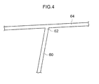
Fig. 4 is a diagram schematically illustrating a centroid of a cross section of the center pillar, a virtual centroid of the cross section of the center pillar and a centroid of a cross section of the roof side rail, at the center pillar upper portion joining structure relating to the exemplary embodiment. -
Fig. 5 is a diagram illustrating a center pillar upper portion joining structure relating to a comparative example, and is a vertical sectional diagram illustrating the vicinity of the joining portion between the upper portion of the center pillar and a roof side rail. -
Fig. 6 is a diagram schematically illustrating a centroid of a cross section of the center pillar and a centroid of a cross section of the roof side rail at the center pillar upper portion joining structure relating to the comparative example. - Herebelow, an exemplary embodiment of the center pillar upper portion joining structure relating to the present invention is described using
Fig. 1 to Fig. 4 . In these drawings, an arrow FR that is shown where appropriate represents a vehicle forward side, an arrow UP represents a vehicle upper side, and an arrow OUT represents a vehicle width direction outer side. -
Fig. 1 shows a schematic side view of a portion of an automobile 10 (a vehicle) in which a center pillar upperportion joining structure 28 of the present exemplary embodiment is employed.Fig. 2 shows a perspective diagram in which the center pillar upperportion joining structure 28 is viewed from the vehicle outer side, andFig. 3 shows a vertical sectional diagram of the center pillar upperportion joining structure 28, cut along line 3-3 ofFig. 2 . - As illustrate in
Fig. 1 , at avehicle side portion 12, afront pillar 14, acenter pillar 16 and arear pillar 18 are disposed in this order from the vehicle forward side. Thefront pillar 14, thecenter pillar 16 and therear pillar 18 are provided as left and right pairs at both sides of theautomobile 10. Thecenter pillar 16 is disposed between a frontdoor aperture portion 20A and a reardoor aperture portion 20B that are formed in thevehicle side portion 12. Thecenter pillar 16 is a vehicle body framework member whose length direction is substantially in the vehicle up-down direction. - An
upper end portion 16A of thecenter pillar 16 is joined to a vehicle front-reardirection middle portion 22A of aroof side rail 22. A roof panel 52 (seeFig. 2 andFig. 3 ) is disposed at an upper portion of the vehicle, and theroof side rail 22 is a vehicle body framework member that is disposed at each of two sides of theroof panel 52, with a length direction thereof substantially in the vehicle front-rear direction. That is, theroof side rail 22 is disposed substantially in the vehicle front-rear direction along the upper edges of the frontdoor aperture portion 20A and the reardoor aperture portion 20B. A joining portion between thecenter pillar 16 and theroof side rail 22 is formed substantially in a "T"' shape. Alower end portion 16B of thecenter pillar 16 is joined to a vehicle front-rear direction middle portion of arocker 24. Therocker 24 is a vehicle body framework member at both sides of a vehicle body lower portion, and is disposed with a length direction thereof substantially in the vehicle front-rear direction. That is, therocker 24 is disposed substantially in the vehicle front-rear direction along the lower edges of the frontdoor aperture portion 20A and the reardoor aperture portion 20B. - An
upper end portion 18A of therear pillar 18 is joined to a vehicle front-rear directionrear end portion 22B of theroof side rail 22. Alower side member 19, which is inflected to the vehicle forward side and extends to the vehicle downward side, is provided at a lower portion of therear pillar 18. A lower end portion of thelower side member 19 is joined to a vehicle front-rear directionrear end portion 24A of therocker 24. - As illustrated in
Fig. 2 andFig. 3 , thecenter pillar 16 is provides with a center pillarinner panel 30, which is disposed at the vehicle with direction inner side, and acenter pillar reinforcement 32, which is disposed at the vehicle width direction outer side of the center pillarinner panel 30. Theroof side rail 22 is provided with a roof side railinner panel 34, which is disposed at the vehicle width direction inner side, and a roof side rail outer panel (side rail outer) 36, which is disposed at the vehicle width direction outer side of the roof side railinner panel 34. A side member outer (also referred to as a side outer panel) 50 is disposed further to the vehicle width direction outer side of the roof side railouter panel 36 and thecenter pillar reinforcement 32. - The roof side rail
inner panel 34 constitutes a vehicle width direction inner side portion of theroof side rail 22, and is disposed with a length direction thereof along the vehicle front-rear direction at the upper portion of the vehicle. As illustrated inFig. 3 and the like, the roof side railinner panel 34 is provided width aside wall portion 34A, anupper flange portion 34B and alower flange portion 34C. A cross section of theside wall portion 34A disposed substantially along the vehicle up-down direction and the vehicle front-rear direction is substantially in an "L" shape. Theupper flange portion 34B extends to the vehicle width direction inner side from an upper end portion of theside wall portion 34A. Thelower flange portion 34C extends diagonally downward to the vehicle outer side from a lower end portion of theside wall portion 34A. - The roof side rail
outer panel 36 is disposed at the vehicle width direction outer side of the roof side railinner panel 34 and extends in the vehicle front-rear direction. As illustrated inFig. 2 , the roof side railouter panel 36 is formed with a substantially hat-shaped cross section that opens to the vehicle width direction inner side. The roof side railouter panel 36 is provided with anupper wall 36A, anouter side wall 36B, alower wall 36C, anupper flange portion 36D and alower flange portion 36E. Theupper wall 36A is disposed substantially along the vehicle width direction. Theouter side wall 36B is disposed diagonally downward to the vehicle outer side from a vehicle width direction outer side end portion of theupper wall 36A. Thelower wall 36C is disposed to downward at the vehicle width direction inner side from a lower end portion of theouter side wall 36B. Theupper flange portion 36D is formed at a vehicle width direction inner side end portion of theupper wall 36A, and thelower flange portion 36E is formed at a vehicle width direction inner side end portion of thelower wall 36C. - Of the roof side rail
outer panel 36, theupper flange portion 36D is superimposed with and joined by welding to the vehicle upper side of theupper flange portion 34B of the roof side railinner panel 34, and thelower flange portion 36E is superposed with and joined by welding to the vehicle width direction outer side of thelower flange portion 34C of the roof side railinner panel 34. - A
flange portion 50A is formed at a vehicle inner side end portion of an upper portion of the side member outer 50. Theflange portion 50A is superposed with and joined by welding to the vehicle upper side of theupper flange portion 36D of the roof side railouter panel 36. Aflange portion 52A is formed at a vehicle width direction outer side end portion of theroof panel 52. Theflange portion 52A is superposed with and joined by welding to the vehicle upper side of theflange portion 50A of the side member outer 50. - A
recess portion 38 is formed in the roof side railouter panel 36 at the joining portion with theupper end portion 16A of thecenter pillar 16. Therecess portion 38 is indented to the vehicle inner side and opens to the vehicle lower side thereof. Therecess portion 38 is provided at positions spanning from theouter side wall 36B to thelower wall 36C of the roof side railouter panel 36. In the present exemplary embodiment, therecess portion 38 is formed in a semi-circle (arch) shape oriented to the vehicle upper side in a vehicle side view (seeFig. 2 ). Therecess portion 38 is described in more detail below. - The center pillar
inner panel 30 is disposed with a length direction thereof substantially in the vehicle up-down direction, and is provided with aninner side wall 30A, afront flange portion 30B and arear flange portion 30C. Theinner side wall 30A is formed with inflected portions along the vehicle up-down direction at the vehicle front and rear thereof. Thefront flange portion 30B extends to the vehicle forward side from a vehicle front end portion of theinner side wall 30A. Therear flange portion 30C extends to the vehicle rearward side from a vehicle rear end portion of the inner side will 30A. - The
center pillar reinforcement 32 is disposed with a length direction thereof substantially in the vehicle up-down direction. A horizontal cross-section shape thereof is substantially a hat shape that opens inward in the vehicle width direction. Thecenter pillar reinforcement 32 is provided with anouter side wall 32A, afront side wall 32B, arear side wall 32C, afront flange portion 32D and arear flange portion 32E. Theouter side wall 32A is at the vehicle width direction outer side and has surface directions in directions substantially along the vehicle front-rear direction and substantially along the vehicle up-down direction. Thefront side wall 32B extends to the vehicle width direction inner side from a vehicle front end portion of theouter side wall 32A. Therear side wall 32C extends to the vehicle width direction inner side from a vehicle rear end portion of theouter side wall 32A. Thefront flange portion 32D extends to the vehicle forward direction from a vehicle inner side end portion of the front side will 32B. Therear flange portion 32E extends to the vehicle rearward direction from a vehicle inner side end portion of therear side wall 32C. - The
front flange portion 32D andrear flange portion 32E of thecenter pillar reinforcement 32 are superposed with and joined by welding to the vehicle width direction outer sides of thefront flange portion 30B andrear flange portion 30C, respectively, of the center pillarinner panel 30. Thus, thecenter pillar 16 is formed in a closed cross-section structure by the center pillarinner panel 30 and thecenter pillar reinforcement 32. In the present exemplary embodiment, position at which thefront flange portion 32D andrear flange portion 32E of thecenter pillar reinforcement 32 are joined to thefront flange portion 30B andrear flange portion 30C of the center pillarinner panel 30 serve as mating flange positions 33 at the vehicle front and rear of thecenter pillar 16. - An upper portion extended portion 42 (an upper portion joining portion) is formed at an upper end portion of the
center pillar reinforcement 32. The upper portion extendedportion 42 is provided extending to the vehicle upper side along the vehicle width direction outer side of theouter side wall 36B of the roof side railouter panel 36. The upper portion extendedportion 42 is disposed so as to close off (cover) therecess portion 38 of the roof side railouter panel 36. In a vehicle side view, the upper portion side of thecenter pillar 16, which is to say, the vicinity of a region joining to theroof side rail 22, is formed as a pair of front and rear circular arc-shaped joining portions 43 (seeFig. 2 ) that gradually widen in the vehicle front-rear direction as they approach theroof side rail 22. - In other words, the circular arc-shaped joining
portions 43 curve such that thefront side wall 32B andrear side wall 32C change direction from the vehicle rear direction to the vehicle front-rear direction. Thus, thefront side wall 32B andrear side wall 32C form curves (curved surface shapes) in a vehicle side view. Terminal ends 43A and 43B of the pair of front and rear circular arc-shaped joiningportions 43 that connect with theouter side wall 36B andlower wall 36C of the roof side railouter panel 36 are provided (seeFig. 2 ) at ridge lines between thefront side wall 32B andrear side wall 32C and theouter side wall 32A at the upper portion extendedportion 42. That is, the terminal ends 43A and 43B of the pair of front and rear circular arc-shaped joiningportions 43 of thecenter pillar reinforcement 32, which are starting points of a common surface with theroof side rail 22, are provided at the upper portion extendedportion 42. - The pair of front and rear circular arc-shaped joining
portions 43 are provided with circular arc curves with different radiuses of curvature in the vehicle side view, and are formed such that the front side has a smoother circular arc curve than the rear side (seeFig. 1 ). The pair of front and rear circular arc-shaped joiningportions 43 may have circular curves with the same radius of curvature in the vehicle side view. - The
lower wall 36C of the roof side railouter panel 36 protrudes in a projection shape to the vehicle outer side at the position of the upper portion extendedportion 42. The upper portion extendedportion 42 is disposed in a state of surface contact with theouter side wall 36B, thelower wall 36C and thelower flange portion 36E at the vehicle front and rear and vehicle upward side of therecess portion 38 of the roof side railouter panel 36. In the state in which the upper portion extendedportion 42 closes off therecess portion 38, an upper end portion of the upper portion extended portion 42 (an upper portion joining portion) is joined by spot welding to theouter side wall 36B at the vehicle upper side of therecess portion 38, and lower end portions (flange portions) of the upper portion extendedportion 42 at the vehicle front and rear are joined by spot welding to thelower flange portion 36E of the roof side rail outer panel 36 (seeFig. 2 ). - Now the
recess portion 38 of the roof side railouter panel 36 is described. The recess portion 38 (seeFig. 3 ) is formed at the vehicle upper side of acentroid 60 of the cross section of the center pillar 16 (a centroid of the closed cross section formed by thecenter pillar reinforcement 32 and the center pillar inner panel 30). - The
recess portion 38 of the roof side rail outer panel 36 (the ridge line with theouter side wall 36B) is disposed, in the vehicle side view, between the terminal ends 43A and 43B of the pair of front and rear circular arc-shaped joiningportion 43 of the upper portion extendedportion 42 of the center pillar reinforcement 32 (seeFig. 2 ). The position of therecess portion 38 is set so as to be between the terminal ends 43A and 43B of the pair of front and rear circular arc-shaped joiningpotions 43 as seen from a vehicle side view in order to suppress a redaction in strength due to therecess portion 38 with respect to an axial force of theroof side rail 22 generated by a front collusion of the vehicle. - In the present exemplary embodiment, front and rear start points 38A and 38B of the ridge line of the
recess portion 38 are provided (seeFig. 2 ) at positions that substantially coincide with extension lines extending upward in the vehicle from the front and rear ridge lines of theouter side wall 32A (inflection potions between theouter side wall 32A and thefront side wall 32B andrear side wall 32C) of thecenter pillar reinforcement 32 that is a framework member. - The upper end portion of the upper portion extended
portion 42 of the center pillar reinforcement 32 (the upper portion joining portion) is joined to the roof side railouter panel 36 at the vehicle upper side of therecess portion 38 so as to close off therecess portion 38. Thus, a centroid of a closed cross section that is constituted by the center pillar reinforcement 32 (the upper portion extended portion 42) and therecess portion 38 of the roof side railouter panel 36, that is, avirtual centroid 62 of the cross section of thecenter pillar 16, is formed upward in the vehicle relative to thecentroid 60 of the cross section of thecenter pillar 16. - In a vehicle front-rear direction view (a vehicle rear elevation view), a lower end portion of a
floor face 38C of the recess portion 38 (a face substantially in the vehicle up-down direction inFig. 3 ) is disposed so as to substantially coincide with extension lines extending upward in the vehicle from themating flange position 33 of thecenter pillar 16. Therefore, in the vehicle front-rear direction view (the vehicle rear elevation view), thecentroid 60 of the cross section of thecenter pillar 16 may smoothly join up with thevirtual centroid 62 of the cross section of thecenter pillar 16. - In the vehicle front-rear direction view (the vehicle rear elevation view), an
upper face 38D of the recess portion 38 (a face that curves substantially to the vehicle width direction inFig. 3 ) is provided upward in the vehicle relative to acentroid 64 of the cross section of theroof side rail 22. Thus, as illustrated inFig. 4 , a structure may be formed in which, in the vehicle side view, thecentroid 64 of the cross section of theroof side rail 22 and thevirtual centroid 62 of the cross section of thecenter pillar 16, which is upward in the vehicle relative to thecentroid 60 of the cross section of thecenter pillar 16, are made to intersect. That is, because theupper face 38D of therecess portion 38 is configured thus, a skewered state can be created between thecentroid 64 of the cross section of theroof side rail 22 that is a vehicle body framework member and thecentroid 60 andvirtual centroid 62 of the cross section of thecenter pillar 16 that is a vehicle body framework member. Consequently, joint failure is eliminated, and joining strength and rigidity between the upper portion of thecenter pillar 16 and theroof side rail 22 are improved. - As illustrated in
Fig. 3 , the present exemplary embodiment is formed as a structure in which thecentroid 64 of the cross section of theroof side rail 22 and thevirtual centroid 62 of the cross section of thecenter pillar 16 are made to intersect in the vehicle front-rear direction view (the vehicle rear elevation view). - Although it is most desirable for the
centroid 64 of the cross section of theroof side rail 22 and thevirtual centroid 62 of the cross section of thecenter pillar 16 to intersect as seen from both a vehicle side view and a vehicle front-rear direction view (a vehicle rear elevation view) (seeFig. 2 andFig. 3 ), configurations are possible in which thecentroid 64 of the cross section of theroof side rail 22 and thevirtual centroid 62 of the cross section of thecenter pillar 16 only intersect as seen from a vehicle side view. - Next, operation and effects of the present exemplary embodiment are described.
- As illustrated in
Fig. 2 andFig. 3 , therecess portion 38 is provided at the lower portion side of theouter side wall 36B of the roof side railouter panel 36 that constitutes theroof side rail 22, and therecess portion 38 is indented to the vehicle inner side and the vehicle lower side thereof is opened. Theupper face 38D of therecess portion 38 is disposed upward in the vehicle relative to thecentroid 64 of the cross section of theroof side rail 22, and the upper end portion of the upper portion extendedportion 42 of thecenter pillar reinforcement 32 constituting thecenter pillar 16 is joined to the roof side railouter panel 36 so as to close off therecess portion 38. Consequently, thevirtual centroid 62 of the cross section of thecenter pillar 16 is formed by the centroid of the closed cross section of thecenter pillar reinforcement 32 and therecess portion 38 of the roof side railouter panel 36 at the vehicle upper side of thecentroid 60 of the cross section of thecenter pillar 16. Thus, because, as illustrated inFig. 4 , thecentroid 64 of the cross section of theroof side rail 22 and thevirtual centroid 62 of the cross section of thecenter pillar 16 that is upward in the vehicle of thecentroid 60 of the cross section of thecenter pillar 16 are caused to intersect in a vehicle side view, a joining loss is eliminated, and joining strength and rigidity between the upper portion of thecenter pillar 16 and theroof side rail 22 may be improved. - As illustrated in
Fig. 3 , in the vehicle front-rear direction view (the vehicle rear elevation view), the lower end portion of thefloor face 38C of therecess portion 38 is disposed so as to substantially coincide with the extension lines extending upward in the vehicle from the mating flange positions 33 at the vehicle front and rear of thecenter pillar 16. Therefore, thecentroid 60 of the cross section of thecenter pillar 16 and thevirtual centroid 62 of the cross section of thecenter pillar 16 may smoothly join up, and joining strength and rigidity between the upper portion of thecenter pillar 16 and theroof side rail 22 may be effectively improved. - The
recess portion 38 of the roof side railouter panel 36 is disposed between the terminal ends 43A and 43B of the pair of front and rear circular arc-shaped joiningportions 43 that are provided at the joining portion between the upper portion extendedportion 42 of thecenter pillar reinforcement 32 and the roof side railouter panel 36. Thus, with respect to an axial force of theroof side rail 22 that is caused by a front collision of the vehicle, a fall in strength of the roof side railouter panel 36 due to therecess portion 38 may be suppressed. -
Fig. 5 shows a center pillar upperportion joining structure 100 relating to a comparative example. In the center pillar upperportion joining structure 100, a roof side railouter panel 104 that constitutes aroof side rail 102 is formed substantially in a hat shape in cross section, which opens inward in the vehicle with direction. This roof side railouter panel 104 is formed with the cross-sectional shape at the vehicle upper side of acenter pillar 106 being substantially the same along the vehicle front-rear direction. In other words, a recess portion is not provided in the roof side railouter panel 104. - An
upper end portion 108A of acenter pillar reinforcement 108 that constitutes thecenter pillar 106 extends to a lower end portion of anouter side face 104A of the roof side railouter panel 104, and theupper end portion 108A of thecenter pillar reinforcement 108 is disposed at theouter side face 104A of the roof side railouter panel 104 in a state of surface contact and joined thereto by spot welding or the like. - In this center pillar upper
portion joining structure 100, in order to prevent buckling due to an axial force of theroof side rail 102 when there is a front collision of the vehicle, a framework cross section of theroof side rail 102 passing along the vehicle front-rear direction takes priority, and thecenter pillar reinforcement 108 that is the framework of thecenter pillar 106 is a structure that covers the vehicle outer side of the roof side railouter panel 104. - In the center pillar upper
portion joining structure 100, as illustrated inFig. 6 , thecentroid 60 of the cross section of thecenter pillar 106 and thecentroid 64 of the cross section of theroof side rail 102 do not join up in a vehicle side view, and there is a joining loss. Therefore, there is room for improvement in the matters of joining strength and rigidity between the upper portion of thecenter pillar 106 and theroof side rail 102. - In contrast, in the center pillar upper
portion joining structure 28 of the present exemplary embodiment, thevirtual centroid 62 of the cross section of thecenter pillar 16 is formed by the centroid of the closed cross section of thecenter pillar reinforcement 32 and therecess portion 38 of the roof side railouter panel 36 at the vehicle upper side of thecentroid 60 of the cross section of thecenter pillar 16, and thecentroid 64 of the cross section of theroof side rail 22 and thevirtual centroid 62 of the cross section of thecenter pillar 16 are made to intersect (seeFig. 4 ). Therefore, there is no joining loss, and joining strength and rigidity between the upper portion of thecenter pillar 16 and theroof side rail 22 may be improved. - In the above exemplary embodiment, the
recess portion 38 of the roof side railouter panel 36 is formed in a semi-circle (arch) toward the vehicle upper side in the vehicle side view. However, this shape is not limiting. For example, a peak portion in the vehicle side view may be in a substantially triangular shape oriented upward in the vehicle, or may be in a rectangular shape or the like. - In the present exemplary embodiment, the front and rear start points 38A and 38B of the ridge line of the
recess portion 38 are specified to be substantially on extension lines extending upward in the vehicle from the front and rear ridge lines of theouter side wall 32A of the center pillar reinforcement 32 (the inflected portions between theouter side wall 32A and thefront side wall 32B andrear side wall 32C), but this is not limiting. That is, the shape and size of therecess portion 38 may be suitably modified, provided therecess portion 38 is disposed between the pair of front and rear terminal ends 43A and 43B of the upper portion extendedportion 42 of thecenter pillar reinforcement 32 in the vehicle side view.
Claims (3)
- A center pillar upper portion joining structure that joins a center pillar to a roof side rail, the center pillar extending along a vehicle up-down direction at a vehicle side portion, the roof side rail being disposed at a vehicle upper side of the center pillar and extending along a vehicle front-rear direction, and the center pillar upper portion joining structure comprising:a recess portion provide at a lower portion side of an outer wall face of a side rail outer that constitutes a vehicle with direction outer side wall of the roof side rail, the recess portion being indented toward a vehicle inner side and opening toward a vehicle lower side, and an upper face of the recess portion being disposed at a vehicle upper side relative to a centroid of a cross section of the roof side rail; andan upper portion joining portion that extends from an upper portion of a center pillar reinforcement constituting a vehicle width direction outer side wall of the center pillar and that is joined two the side rail outer so as to close off the recess portion.
- The center pillar upper portion joining structure according two claim 1, wherein, from a vehicle front-rear direction view, a lower end portion of a floor face of the recess portion is disposed so as to substantially coincide with extension lines extending upward in the vehicle from mating flange positions at the vehicle frond and rear of the center pillar.
- The center pillar upper portion joining structure according to claim 1 or claim 2, wherein the recess portion is disposed between terminal ends of a pair of front and rear circular arc-shaped connection portions that are provided at a joining portion between the center pillar reinforcement and the side rail outer and that are each formed in a circular are shape from a vehicle side view.
Applications Claiming Priority (1)
| Application Number | Priority Date | Filing Date | Title |
|---|---|---|---|
| PCT/JP2011/051499 WO2012101783A1 (en) | 2011-01-26 | 2011-01-26 | Center pillar upper portion coupling structure |
Publications (3)
| Publication Number | Publication Date |
|---|---|
| EP2669148A1 true EP2669148A1 (en) | 2013-12-04 |
| EP2669148A4 EP2669148A4 (en) | 2014-08-20 |
| EP2669148B1 EP2669148B1 (en) | 2016-07-13 |
Family
ID=46580388
Family Applications (1)
| Application Number | Title | Priority Date | Filing Date |
|---|---|---|---|
| EP11854533.4A Not-in-force EP2669148B1 (en) | 2011-01-26 | 2011-01-26 | Center pillar upper portion coupling structure |
Country Status (6)
| Country | Link |
|---|---|
| US (1) | US8845009B2 (en) |
| EP (1) | EP2669148B1 (en) |
| JP (1) | JP5141847B2 (en) |
| KR (1) | KR101370729B1 (en) |
| CN (1) | CN102781766B (en) |
| WO (1) | WO2012101783A1 (en) |
Families Citing this family (13)
| Publication number | Priority date | Publication date | Assignee | Title |
|---|---|---|---|---|
| DE102011120519A1 (en) * | 2011-12-08 | 2013-06-13 | GM Global Technology Operations LLC (n. d. Gesetzen des Staates Delaware) | Reinforcement for a vehicle pillar, in particular the B-pillar of a vehicle |
| CN103863403B (en) * | 2012-12-12 | 2016-12-07 | 北汽福田汽车股份有限公司 | Mounting structure and automobile for automotive side wall central column |
| US10023237B2 (en) | 2013-11-15 | 2018-07-17 | Autotech Engineering A.I.E. | Beam for producing a metal framework |
| JP6311989B2 (en) * | 2014-12-03 | 2018-04-18 | スズキ株式会社 | Junction structure |
| DE102016001241A1 (en) * | 2016-02-04 | 2017-08-10 | GM Global Technology Operations LLC (n. d. Ges. d. Staates Delaware) | Structure node for a motor vehicle body |
| JP6673163B2 (en) * | 2016-11-28 | 2020-03-25 | トヨタ自動車株式会社 | Central structure of vehicle |
| JP6575015B2 (en) * | 2017-07-07 | 2019-09-18 | 本田技研工業株式会社 | Body structure |
| JP6538133B2 (en) * | 2017-09-29 | 2019-07-03 | 本田技研工業株式会社 | Body side structure |
| JP6973499B2 (en) * | 2017-11-01 | 2021-12-01 | 日本製鉄株式会社 | Laminated joint structure |
| JP7013953B2 (en) * | 2018-03-08 | 2022-02-01 | トヨタ自動車株式会社 | Pillar superstructure |
| KR102352965B1 (en) * | 2019-11-25 | 2022-01-21 | 주식회사 호원 | Light weight type side outer assembley |
| JP7223050B2 (en) * | 2021-03-29 | 2023-02-15 | 本田技研工業株式会社 | Body side structure |
| JP7834537B2 (en) | 2022-03-31 | 2026-03-24 | 本田技研工業株式会社 | Method for assembling the superstructure and body of a vehicle. |
Family Cites Families (16)
| Publication number | Priority date | Publication date | Assignee | Title |
|---|---|---|---|---|
| JPS616860A (en) | 1984-06-20 | 1986-01-13 | Mitsubishi Electric Corp | Color solid-state image pickup device |
| JPH0616860Y2 (en) * | 1987-10-16 | 1994-05-02 | トヨタ自動車株式会社 | Center pillar and roof side rail connection structure |
| JP2552326Y2 (en) * | 1991-06-11 | 1997-10-29 | 三菱自動車工業株式会社 | Structure of seat belt reinforcement |
| JPH0616860A (en) * | 1992-06-29 | 1994-01-25 | Junjiro Aoki | Production of porous polymer microsphere |
| JPH0976937A (en) * | 1995-09-11 | 1997-03-25 | Nissan Motor Co Ltd | Joint structure of vehicle body frame members |
| KR100194711B1 (en) * | 1995-12-12 | 1999-06-15 | 정몽규 | Shock Absorber of Vehicle Door |
| JP3293120B2 (en) * | 1996-06-14 | 2002-06-17 | 日産自動車株式会社 | Frame body member connection structure |
| JP3866416B2 (en) | 1998-06-15 | 2007-01-10 | 富士重工業株式会社 | Automobile center pillar upper coupling structure |
| KR100391537B1 (en) * | 1999-12-13 | 2003-07-12 | 기아자동차주식회사 | Center pillar assembly for a motor vehicle |
| DE10011946A1 (en) * | 2000-03-11 | 2001-09-13 | Opel Adam Ag | Connection between the roof and the side wall of a motor vehicle body |
| JP4145052B2 (en) | 2002-01-22 | 2008-09-03 | 富士重工業株式会社 | Automobile center pillar upper coupling structure |
| JP2003261063A (en) * | 2002-03-07 | 2003-09-16 | Araco Corp | Body structure of automobile |
| JP4483768B2 (en) * | 2005-11-08 | 2010-06-16 | トヨタ自動車株式会社 | Roof side structure |
| JP2007313963A (en) * | 2006-05-24 | 2007-12-06 | Toyota Motor Corp | Roof side structure |
| JP4265647B2 (en) * | 2006-11-29 | 2009-05-20 | トヨタ自動車株式会社 | Body side structure |
| JP2010162973A (en) * | 2009-01-14 | 2010-07-29 | Toyota Motor Corp | Pillar upper section connecting structure |
-
2011
- 2011-01-26 CN CN201180012636.2A patent/CN102781766B/en not_active Expired - Fee Related
- 2011-01-26 JP JP2012503159A patent/JP5141847B2/en not_active Expired - Fee Related
- 2011-01-26 US US13/518,763 patent/US8845009B2/en not_active Expired - Fee Related
- 2011-01-26 WO PCT/JP2011/051499 patent/WO2012101783A1/en not_active Ceased
- 2011-01-26 EP EP11854533.4A patent/EP2669148B1/en not_active Not-in-force
- 2011-01-26 KR KR1020127019898A patent/KR101370729B1/en not_active Expired - Fee Related
Also Published As
| Publication number | Publication date |
|---|---|
| JPWO2012101783A1 (en) | 2014-06-30 |
| US20130300155A1 (en) | 2013-11-14 |
| CN102781766A (en) | 2012-11-14 |
| KR20120120266A (en) | 2012-11-01 |
| WO2012101783A1 (en) | 2012-08-02 |
| CN102781766B (en) | 2014-11-19 |
| JP5141847B2 (en) | 2013-02-13 |
| EP2669148B1 (en) | 2016-07-13 |
| US8845009B2 (en) | 2014-09-30 |
| KR101370729B1 (en) | 2014-03-06 |
| EP2669148A4 (en) | 2014-08-20 |
Similar Documents
| Publication | Publication Date | Title |
|---|---|---|
| EP2669148B1 (en) | Center pillar upper portion coupling structure | |
| US8282154B2 (en) | Vehicle body lateral side portion structure | |
| US8556336B2 (en) | Vehicle body panel joining structure | |
| US9643655B2 (en) | Vehicle side portion structure | |
| JP6256519B2 (en) | Vehicle side body structure | |
| US20140339855A1 (en) | Pillar structure for vehicle | |
| JP6357886B2 (en) | Vehicle side structure | |
| JP6669089B2 (en) | Side body structure of vehicle | |
| CN107804373B (en) | Vehicle body superstructure | |
| JP2012111380A (en) | Door structure | |
| JP2012035646A (en) | Vehicle body lower structure | |
| US11142253B2 (en) | Vehicle side body structure | |
| CN111703506B (en) | Vehicle lower part structure | |
| US11548562B2 (en) | Vehicle body rear part structure | |
| JP2019116123A (en) | Vehicle body front section structure | |
| US10822038B2 (en) | Vehicle lower portion structure | |
| JP6966297B2 (en) | Body structure | |
| US11679810B2 (en) | Vehicle body side structure | |
| US9738325B2 (en) | Vehicle front section structure | |
| JP2023134951A (en) | front pillar for vehicle | |
| JP6304327B2 (en) | Upper body structure |
Legal Events
| Date | Code | Title | Description |
|---|---|---|---|
| PUAI | Public reference made under article 153(3) epc to a published international application that has entered the european phase |
Free format text: ORIGINAL CODE: 0009012 |
|
| 17P | Request for examination filed |
Effective date: 20120710 |
|
| AK | Designated contracting states |
Kind code of ref document: A1 Designated state(s): AL AT BE BG CH CY CZ DE DK EE ES FI FR GB GR HR HU IE IS IT LI LT LU LV MC MK MT NL NO PL PT RO RS SE SI SK SM TR |
|
| DAX | Request for extension of the european patent (deleted) | ||
| A4 | Supplementary search report drawn up and despatched |
Effective date: 20140721 |
|
| RIC1 | Information provided on ipc code assigned before grant |
Ipc: B62D 25/04 20060101AFI20140715BHEP Ipc: B62D 25/06 20060101ALI20140715BHEP |
|
| GRAP | Despatch of communication of intention to grant a patent |
Free format text: ORIGINAL CODE: EPIDOSNIGR1 |
|
| INTG | Intention to grant announced |
Effective date: 20150810 |
|
| INTG | Intention to grant announced |
Effective date: 20160126 |
|
| GRAS | Grant fee paid |
Free format text: ORIGINAL CODE: EPIDOSNIGR3 |
|
| GRAA | (expected) grant |
Free format text: ORIGINAL CODE: 0009210 |
|
| AK | Designated contracting states |
Kind code of ref document: B1 Designated state(s): AL AT BE BG CH CY CZ DE DK EE ES FI FR GB GR HR HU IE IS IT LI LT LU LV MC MK MT NL NO PL PT RO RS SE SI SK SM TR |
|
| REG | Reference to a national code |
Ref country code: GB Ref legal event code: FG4D |
|
| REG | Reference to a national code |
Ref country code: AT Ref legal event code: REF Ref document number: 812036 Country of ref document: AT Kind code of ref document: T Effective date: 20160715 Ref country code: CH Ref legal event code: EP |
|
| REG | Reference to a national code |
Ref country code: IE Ref legal event code: FG4D |
|
| REG | Reference to a national code |
Ref country code: DE Ref legal event code: R096 Ref document number: 602011028230 Country of ref document: DE |
|
| REG | Reference to a national code |
Ref country code: DE Ref legal event code: R084 Ref document number: 602011028230 Country of ref document: DE |
|
| REG | Reference to a national code |
Ref country code: LT Ref legal event code: MG4D |
|
| REG | Reference to a national code |
Ref country code: NL Ref legal event code: MP Effective date: 20160713 |
|
| REG | Reference to a national code |
Ref country code: GB Ref legal event code: 746 Effective date: 20161027 |
|
| REG | Reference to a national code |
Ref country code: FR Ref legal event code: PLFP Year of fee payment: 7 Ref country code: AT Ref legal event code: MK05 Ref document number: 812036 Country of ref document: AT Kind code of ref document: T Effective date: 20160713 |
|
| PG25 | Lapsed in a contracting state [announced via postgrant information from national office to epo] |
Ref country code: LT Free format text: LAPSE BECAUSE OF FAILURE TO SUBMIT A TRANSLATION OF THE DESCRIPTION OR TO PAY THE FEE WITHIN THE PRESCRIBED TIME-LIMIT Effective date: 20160713 Ref country code: FI Free format text: LAPSE BECAUSE OF FAILURE TO SUBMIT A TRANSLATION OF THE DESCRIPTION OR TO PAY THE FEE WITHIN THE PRESCRIBED TIME-LIMIT Effective date: 20160713 Ref country code: NO Free format text: LAPSE BECAUSE OF FAILURE TO SUBMIT A TRANSLATION OF THE DESCRIPTION OR TO PAY THE FEE WITHIN THE PRESCRIBED TIME-LIMIT Effective date: 20161013 Ref country code: NL Free format text: LAPSE BECAUSE OF FAILURE TO SUBMIT A TRANSLATION OF THE DESCRIPTION OR TO PAY THE FEE WITHIN THE PRESCRIBED TIME-LIMIT Effective date: 20160713 Ref country code: IS Free format text: LAPSE BECAUSE OF FAILURE TO SUBMIT A TRANSLATION OF THE DESCRIPTION OR TO PAY THE FEE WITHIN THE PRESCRIBED TIME-LIMIT Effective date: 20161113 Ref country code: IT Free format text: LAPSE BECAUSE OF FAILURE TO SUBMIT A TRANSLATION OF THE DESCRIPTION OR TO PAY THE FEE WITHIN THE PRESCRIBED TIME-LIMIT Effective date: 20160713 Ref country code: HR Free format text: LAPSE BECAUSE OF FAILURE TO SUBMIT A TRANSLATION OF THE DESCRIPTION OR TO PAY THE FEE WITHIN THE PRESCRIBED TIME-LIMIT Effective date: 20160713 Ref country code: RS Free format text: LAPSE BECAUSE OF FAILURE TO SUBMIT A TRANSLATION OF THE DESCRIPTION OR TO PAY THE FEE WITHIN THE PRESCRIBED TIME-LIMIT Effective date: 20160713 |
|
| PG25 | Lapsed in a contracting state [announced via postgrant information from national office to epo] |
Ref country code: PL Free format text: LAPSE BECAUSE OF FAILURE TO SUBMIT A TRANSLATION OF THE DESCRIPTION OR TO PAY THE FEE WITHIN THE PRESCRIBED TIME-LIMIT Effective date: 20160713 Ref country code: ES Free format text: LAPSE BECAUSE OF FAILURE TO SUBMIT A TRANSLATION OF THE DESCRIPTION OR TO PAY THE FEE WITHIN THE PRESCRIBED TIME-LIMIT Effective date: 20160713 Ref country code: PT Free format text: LAPSE BECAUSE OF FAILURE TO SUBMIT A TRANSLATION OF THE DESCRIPTION OR TO PAY THE FEE WITHIN THE PRESCRIBED TIME-LIMIT Effective date: 20161114 Ref country code: SE Free format text: LAPSE BECAUSE OF FAILURE TO SUBMIT A TRANSLATION OF THE DESCRIPTION OR TO PAY THE FEE WITHIN THE PRESCRIBED TIME-LIMIT Effective date: 20160713 Ref country code: BE Free format text: LAPSE BECAUSE OF FAILURE TO SUBMIT A TRANSLATION OF THE DESCRIPTION OR TO PAY THE FEE WITHIN THE PRESCRIBED TIME-LIMIT Effective date: 20160713 Ref country code: GR Free format text: LAPSE BECAUSE OF FAILURE TO SUBMIT A TRANSLATION OF THE DESCRIPTION OR TO PAY THE FEE WITHIN THE PRESCRIBED TIME-LIMIT Effective date: 20161014 Ref country code: AT Free format text: LAPSE BECAUSE OF FAILURE TO SUBMIT A TRANSLATION OF THE DESCRIPTION OR TO PAY THE FEE WITHIN THE PRESCRIBED TIME-LIMIT Effective date: 20160713 Ref country code: LV Free format text: LAPSE BECAUSE OF FAILURE TO SUBMIT A TRANSLATION OF THE DESCRIPTION OR TO PAY THE FEE WITHIN THE PRESCRIBED TIME-LIMIT Effective date: 20160713 |
|
| REG | Reference to a national code |
Ref country code: DE Ref legal event code: R097 Ref document number: 602011028230 Country of ref document: DE |
|
| PG25 | Lapsed in a contracting state [announced via postgrant information from national office to epo] |
Ref country code: RO Free format text: LAPSE BECAUSE OF FAILURE TO SUBMIT A TRANSLATION OF THE DESCRIPTION OR TO PAY THE FEE WITHIN THE PRESCRIBED TIME-LIMIT Effective date: 20160713 Ref country code: EE Free format text: LAPSE BECAUSE OF FAILURE TO SUBMIT A TRANSLATION OF THE DESCRIPTION OR TO PAY THE FEE WITHIN THE PRESCRIBED TIME-LIMIT Effective date: 20160713 |
|
| PLBE | No opposition filed within time limit |
Free format text: ORIGINAL CODE: 0009261 |
|
| STAA | Information on the status of an ep patent application or granted ep patent |
Free format text: STATUS: NO OPPOSITION FILED WITHIN TIME LIMIT |
|
| PG25 | Lapsed in a contracting state [announced via postgrant information from national office to epo] |
Ref country code: CZ Free format text: LAPSE BECAUSE OF FAILURE TO SUBMIT A TRANSLATION OF THE DESCRIPTION OR TO PAY THE FEE WITHIN THE PRESCRIBED TIME-LIMIT Effective date: 20160713 Ref country code: SK Free format text: LAPSE BECAUSE OF FAILURE TO SUBMIT A TRANSLATION OF THE DESCRIPTION OR TO PAY THE FEE WITHIN THE PRESCRIBED TIME-LIMIT Effective date: 20160713 Ref country code: DK Free format text: LAPSE BECAUSE OF FAILURE TO SUBMIT A TRANSLATION OF THE DESCRIPTION OR TO PAY THE FEE WITHIN THE PRESCRIBED TIME-LIMIT Effective date: 20160713 Ref country code: SM Free format text: LAPSE BECAUSE OF FAILURE TO SUBMIT A TRANSLATION OF THE DESCRIPTION OR TO PAY THE FEE WITHIN THE PRESCRIBED TIME-LIMIT Effective date: 20160713 Ref country code: BG Free format text: LAPSE BECAUSE OF FAILURE TO SUBMIT A TRANSLATION OF THE DESCRIPTION OR TO PAY THE FEE WITHIN THE PRESCRIBED TIME-LIMIT Effective date: 20161013 |
|
| 26N | No opposition filed |
Effective date: 20170418 |
|
| PG25 | Lapsed in a contracting state [announced via postgrant information from national office to epo] |
Ref country code: SI Free format text: LAPSE BECAUSE OF FAILURE TO SUBMIT A TRANSLATION OF THE DESCRIPTION OR TO PAY THE FEE WITHIN THE PRESCRIBED TIME-LIMIT Effective date: 20160713 |
|
| REG | Reference to a national code |
Ref country code: CH Ref legal event code: PL |
|
| PG25 | Lapsed in a contracting state [announced via postgrant information from national office to epo] |
Ref country code: MC Free format text: LAPSE BECAUSE OF FAILURE TO SUBMIT A TRANSLATION OF THE DESCRIPTION OR TO PAY THE FEE WITHIN THE PRESCRIBED TIME-LIMIT Effective date: 20160713 |
|
| PG25 | Lapsed in a contracting state [announced via postgrant information from national office to epo] |
Ref country code: LI Free format text: LAPSE BECAUSE OF NON-PAYMENT OF DUE FEES Effective date: 20170131 Ref country code: CH Free format text: LAPSE BECAUSE OF NON-PAYMENT OF DUE FEES Effective date: 20170131 |
|
| REG | Reference to a national code |
Ref country code: IE Ref legal event code: MM4A |
|
| PG25 | Lapsed in a contracting state [announced via postgrant information from national office to epo] |
Ref country code: LU Free format text: LAPSE BECAUSE OF NON-PAYMENT OF DUE FEES Effective date: 20170126 |
|
| REG | Reference to a national code |
Ref country code: FR Ref legal event code: PLFP Year of fee payment: 8 |
|
| PG25 | Lapsed in a contracting state [announced via postgrant information from national office to epo] |
Ref country code: IE Free format text: LAPSE BECAUSE OF NON-PAYMENT OF DUE FEES Effective date: 20170126 |
|
| PG25 | Lapsed in a contracting state [announced via postgrant information from national office to epo] |
Ref country code: MT Free format text: LAPSE BECAUSE OF NON-PAYMENT OF DUE FEES Effective date: 20170126 |
|
| PG25 | Lapsed in a contracting state [announced via postgrant information from national office to epo] |
Ref country code: AL Free format text: LAPSE BECAUSE OF FAILURE TO SUBMIT A TRANSLATION OF THE DESCRIPTION OR TO PAY THE FEE WITHIN THE PRESCRIBED TIME-LIMIT Effective date: 20160713 |
|
| PG25 | Lapsed in a contracting state [announced via postgrant information from national office to epo] |
Ref country code: HU Free format text: LAPSE BECAUSE OF FAILURE TO SUBMIT A TRANSLATION OF THE DESCRIPTION OR TO PAY THE FEE WITHIN THE PRESCRIBED TIME-LIMIT; INVALID AB INITIO Effective date: 20110126 |
|
| PG25 | Lapsed in a contracting state [announced via postgrant information from national office to epo] |
Ref country code: CY Free format text: LAPSE BECAUSE OF NON-PAYMENT OF DUE FEES Effective date: 20160713 |
|
| PG25 | Lapsed in a contracting state [announced via postgrant information from national office to epo] |
Ref country code: MK Free format text: LAPSE BECAUSE OF FAILURE TO SUBMIT A TRANSLATION OF THE DESCRIPTION OR TO PAY THE FEE WITHIN THE PRESCRIBED TIME-LIMIT Effective date: 20160713 |
|
| PG25 | Lapsed in a contracting state [announced via postgrant information from national office to epo] |
Ref country code: TR Free format text: LAPSE BECAUSE OF FAILURE TO SUBMIT A TRANSLATION OF THE DESCRIPTION OR TO PAY THE FEE WITHIN THE PRESCRIBED TIME-LIMIT Effective date: 20160713 |
|
| PGFP | Annual fee paid to national office [announced via postgrant information from national office to epo] |
Ref country code: GB Payment date: 20211206 Year of fee payment: 12 Ref country code: FR Payment date: 20211217 Year of fee payment: 12 |
|
| PGFP | Annual fee paid to national office [announced via postgrant information from national office to epo] |
Ref country code: DE Payment date: 20211130 Year of fee payment: 12 |
|
| REG | Reference to a national code |
Ref country code: DE Ref legal event code: R119 Ref document number: 602011028230 Country of ref document: DE |
|
| GBPC | Gb: european patent ceased through non-payment of renewal fee |
Effective date: 20230126 |
|
| PG25 | Lapsed in a contracting state [announced via postgrant information from national office to epo] |
Ref country code: GB Free format text: LAPSE BECAUSE OF NON-PAYMENT OF DUE FEES Effective date: 20230126 Ref country code: DE Free format text: LAPSE BECAUSE OF NON-PAYMENT OF DUE FEES Effective date: 20230801 |
|
| PG25 | Lapsed in a contracting state [announced via postgrant information from national office to epo] |
Ref country code: FR Free format text: LAPSE BECAUSE OF NON-PAYMENT OF DUE FEES Effective date: 20230131 |