EP2668991A1 - Filter assembly and process for filtering syngas - Google Patents
Filter assembly and process for filtering syngas Download PDFInfo
- Publication number
- EP2668991A1 EP2668991A1 EP12169749.4A EP12169749A EP2668991A1 EP 2668991 A1 EP2668991 A1 EP 2668991A1 EP 12169749 A EP12169749 A EP 12169749A EP 2668991 A1 EP2668991 A1 EP 2668991A1
- Authority
- EP
- European Patent Office
- Prior art keywords
- clusters
- filter assembly
- filter
- assembly according
- tube sheet
- Prior art date
- Legal status (The legal status is an assumption and is not a legal conclusion. Google has not performed a legal analysis and makes no representation as to the accuracy of the status listed.)
- Withdrawn
Links
- 238000001914 filtration Methods 0.000 title claims description 5
- 238000000034 method Methods 0.000 title claims 2
- 238000002485 combustion reaction Methods 0.000 claims description 2
- 239000007789 gas Substances 0.000 description 14
- 239000000428 dust Substances 0.000 description 7
- 238000004140 cleaning Methods 0.000 description 5
- 239000002245 particle Substances 0.000 description 5
- 230000000712 assembly Effects 0.000 description 4
- 238000000429 assembly Methods 0.000 description 4
- 239000000706 filtrate Substances 0.000 description 3
- 239000010881 fly ash Substances 0.000 description 3
- 238000012856 packing Methods 0.000 description 3
- 239000002893 slag Substances 0.000 description 3
- 239000007787 solid Substances 0.000 description 3
- IJGRMHOSHXDMSA-UHFFFAOYSA-N Atomic nitrogen Chemical compound N#N IJGRMHOSHXDMSA-UHFFFAOYSA-N 0.000 description 2
- 238000004891 communication Methods 0.000 description 2
- 230000000717 retained effect Effects 0.000 description 2
- 239000002028 Biomass Substances 0.000 description 1
- OKTJSMMVPCPJKN-UHFFFAOYSA-N Carbon Chemical compound [C] OKTJSMMVPCPJKN-UHFFFAOYSA-N 0.000 description 1
- 239000002956 ash Substances 0.000 description 1
- 238000007664 blowing Methods 0.000 description 1
- 239000006227 byproduct Substances 0.000 description 1
- 229910052799 carbon Inorganic materials 0.000 description 1
- 239000000919 ceramic Substances 0.000 description 1
- 239000000356 contaminant Substances 0.000 description 1
- 238000011143 downstream manufacturing Methods 0.000 description 1
- 230000000694 effects Effects 0.000 description 1
- 238000002309 gasification Methods 0.000 description 1
- 230000014509 gene expression Effects 0.000 description 1
- 239000011261 inert gas Substances 0.000 description 1
- 238000012423 maintenance Methods 0.000 description 1
- 239000002184 metal Substances 0.000 description 1
- 229910052757 nitrogen Inorganic materials 0.000 description 1
- 239000011148 porous material Substances 0.000 description 1
Images
Classifications
-
- B—PERFORMING OPERATIONS; TRANSPORTING
- B01—PHYSICAL OR CHEMICAL PROCESSES OR APPARATUS IN GENERAL
- B01D—SEPARATION
- B01D46/00—Filters or filtering processes specially modified for separating dispersed particles from gases or vapours
- B01D46/24—Particle separators, e.g. dust precipitators, using rigid hollow filter bodies
- B01D46/2403—Particle separators, e.g. dust precipitators, using rigid hollow filter bodies characterised by the physical shape or structure of the filtering element
- B01D46/2407—Filter candles
-
- B—PERFORMING OPERATIONS; TRANSPORTING
- B01—PHYSICAL OR CHEMICAL PROCESSES OR APPARATUS IN GENERAL
- B01D—SEPARATION
- B01D46/00—Filters or filtering processes specially modified for separating dispersed particles from gases or vapours
- B01D46/24—Particle separators, e.g. dust precipitators, using rigid hollow filter bodies
- B01D46/2403—Particle separators, e.g. dust precipitators, using rigid hollow filter bodies characterised by the physical shape or structure of the filtering element
- B01D46/2418—Honeycomb filters
- B01D46/2451—Honeycomb filters characterized by the geometrical structure, shape, pattern or configuration or parameters related to the geometry of the structure
- B01D46/2486—Honeycomb filters characterized by the geometrical structure, shape, pattern or configuration or parameters related to the geometry of the structure characterised by the shapes or configurations
- B01D46/2492—Hexagonal
-
- B—PERFORMING OPERATIONS; TRANSPORTING
- B01—PHYSICAL OR CHEMICAL PROCESSES OR APPARATUS IN GENERAL
- B01D—SEPARATION
- B01D46/00—Filters or filtering processes specially modified for separating dispersed particles from gases or vapours
- B01D46/24—Particle separators, e.g. dust precipitators, using rigid hollow filter bodies
- B01D46/2403—Particle separators, e.g. dust precipitators, using rigid hollow filter bodies characterised by the physical shape or structure of the filtering element
- B01D46/2418—Honeycomb filters
- B01D46/2451—Honeycomb filters characterized by the geometrical structure, shape, pattern or configuration or parameters related to the geometry of the structure
- B01D46/2455—Honeycomb filters characterized by the geometrical structure, shape, pattern or configuration or parameters related to the geometry of the structure of the whole honeycomb or segments
-
- B—PERFORMING OPERATIONS; TRANSPORTING
- B01—PHYSICAL OR CHEMICAL PROCESSES OR APPARATUS IN GENERAL
- B01D—SEPARATION
- B01D46/00—Filters or filtering processes specially modified for separating dispersed particles from gases or vapours
- B01D46/24—Particle separators, e.g. dust precipitators, using rigid hollow filter bodies
- B01D46/2403—Particle separators, e.g. dust precipitators, using rigid hollow filter bodies characterised by the physical shape or structure of the filtering element
- B01D46/2418—Honeycomb filters
- B01D46/2451—Honeycomb filters characterized by the geometrical structure, shape, pattern or configuration or parameters related to the geometry of the structure
- B01D46/2482—Thickness, height, width, length or diameter
-
- B—PERFORMING OPERATIONS; TRANSPORTING
- B01—PHYSICAL OR CHEMICAL PROCESSES OR APPARATUS IN GENERAL
- B01D—SEPARATION
- B01D46/00—Filters or filtering processes specially modified for separating dispersed particles from gases or vapours
- B01D46/24—Particle separators, e.g. dust precipitators, using rigid hollow filter bodies
- B01D46/2403—Particle separators, e.g. dust precipitators, using rigid hollow filter bodies characterised by the physical shape or structure of the filtering element
- B01D46/2418—Honeycomb filters
- B01D46/2451—Honeycomb filters characterized by the geometrical structure, shape, pattern or configuration or parameters related to the geometry of the structure
- B01D46/2484—Cell density, area or aspect ratio
-
- B—PERFORMING OPERATIONS; TRANSPORTING
- B01—PHYSICAL OR CHEMICAL PROCESSES OR APPARATUS IN GENERAL
- B01D—SEPARATION
- B01D46/00—Filters or filtering processes specially modified for separating dispersed particles from gases or vapours
- B01D46/66—Regeneration of the filtering material or filter elements inside the filter
- B01D46/70—Regeneration of the filtering material or filter elements inside the filter by acting counter-currently on the filtering surface, e.g. by flushing on the non-cake side of the filter
- B01D46/71—Regeneration of the filtering material or filter elements inside the filter by acting counter-currently on the filtering surface, e.g. by flushing on the non-cake side of the filter with pressurised gas, e.g. pulsed air
Definitions
- the invention pertains to a filter assembly, comprising a filter house with an inner chamber partitioned by a tube sheet separating an inlet compartment with an inlet and an outlet compartment with a filtrate outlet, wherein the main tube sheet carries a plurality of clusters of tubular filter elements defining a flow path from the inlet compartment to the outlet compartment, such as candle filters.
- the tubular filter elements typically have a tubular body of a porous structure extending between an open end and a closed end.
- the invention also relates to the use of such filter assemblies, for instance for the removal of fine ash or slag particles from a gaseous medium, such as an outlet stream of gasification reactor before the gas enters downstream processing units. Fly ash and slag particles are retained by the wall of the filter element.
- Filter assemblies of this kind can be cleaned by a reverse back flow induced by a pulse of an inert gas.
- the clusters can be capped with a tapering duct extending between a large end enclosing the open ends of the filter elements of the corresponding cluster, and a smaller open end extending into the outlet compartment.
- a blaster is directed to the open end of the corresponding tapering duct. The blaster can blast a pulse of an inert cleaning gas, such as nitrogen, into the tapering duct.
- the high pressure pulse of cleaning gas causes filtered syngas to enter the duct, creating a pressure wave through the filter elements which results in a temporary reverse flow through the filter elements. This dislodges solids from the filter elements. The dislodged solids drop down to the bottom of the filter house.
- the recovered fly ash and slag particles can either be recycled to the gasifier or discharged as a by-product.
- a filter assembly comprising a filter house with an inner chamber partitioned by a main tube sheet dividing the inner chamber into an inlet compartment with an inlet and an outlet compartment with a filtrate outlet.
- the main tube sheet carries a plurality of clusters of tubular filter elements defining a flow path from the inlet compartment to the outlet compartment.
- Each tubular filter element has a tubular body extending between an open end and a closed end.
- adjacent clusters have parallel adjacent side faces.
- cross section and “cross sectional” refer to the cross section along a plane perpendicular to a longitudinal axis of the filter elements.
- the clusters can for example have a polygonal cross section, e.g., a triangular, square or hexagonal cross section.
- the use of cluster with a polygonal cross section allows dense packing of the clusters within the filter assembly. Additionally, given a certain centre-to-centre distance and diameter of the filter elements, more filters can be packed within a polygonal cluster than in a cluster of a different outline, in particular a circular outline. Both effects contribute to maximization of the number of filter elements carried by a single main tube sheet, particularly a circular main tube sheet. Hence, the ratio between the number of filter elements and the required diameter of the main tube sheet increases, resulting in a reduction of the required size of the filter house or pressure vessel.
- the clusters can for instance be capped with a tapering duct extending between a large end enclosing the open ends of the filter elements of the corresponding cluster, and a smaller open end extending into the outlet compartment, wherein at a distance from each of the open ends of the tapering ducts, a blaster is directed to the open end of the corresponding tapering duct.
- the larger open ends of the tapering ducts can have an outline corresponding to the cross sectional shape of the corresponding clusters.
- the larger open ends of the tapering ducts and the clusters can have concentric polygonal, e.g., hexagonal outlines.
- the cross sectional outline of the tapering ducts gradually changes from hexagonal at the larger end to cylindrical at the smaller top ends.
- the main tube sheet can be provided with openings, wherein a secondary tube sheet carrying a cluster of tubular filter elements is suspended in each of said openings. This allows installing and removal of the clusters as subassemblies, allowing easier maintenance outside the filter vessel.
- the secondary tube sheets, the openings in the main tube sheet, and the clusters may have concentric polygonal, e.g., hexagonal outlines.
- all clusters are equally sized and shaped. In case of hexagonal clusters, this results in a regular honeycomb structure.
- each cluster may for example comprise more than 50 filter elements per m 2 .
- the filter elements within the clusters can be equally sized and equidistantly arranged with a centre-to-centre distance of at least 1,5 times the filter element diameter.
- the centre-to-centre distance can be at least 100 mm.
- the filter assembly may comprise any suitable number of clusters.
- a filter assembly for filtering synthetic gas discharged by a gasifier may comprise more than 45 clusters.
- the filter assembly may be provided with an inlet and a filtrate outlet having a flow capacity of at least 5 m 3 /sec.
- the width of the gaps between adjacent clusters can for instance be about 200 mm or less. Larger gaps can also be used if so desired.
- the filter elements comprise a tubular wall, e.g., of a porous material, which may for instance be ceramic and/or metallic.
- the tubular body of the filter element typically extends between an open end in open communication with the outlet compartment, and a closed end extending into the inlet compartment.
- the open end of the filter element can be connected to the tube sheet in line with one of the openings.
- the opposite end of the filter is closed.
- the filter elements will generally have a circular cross section.
- the filter elements may have a polygonal cross section, such as a triangular, square or hexagonal cross section, to enable dense packing of the filter elements.
- the disclosed filter assemblies are particularly suitable for filtering syngas formed by the partial combustion of a carbonaceous feed, such as oil, carbon or biomass.
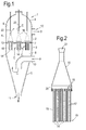
- FIG. 1 shows a filter assembly 1 in a longitudinal cross section.
- the filter assembly 1 comprises a filter house 2, typically formed of a cylindrical body 3 capped with a semispherical top 4.
- the shown embodiment comprises a conical lower section 5 narrowing down in downward direction.
- the filter house 2 encloses an inner chamber 6 partitioned by a main tube sheet 7 which divides the inner chamber 6 into an inlet compartment 8 and an outlet compartment 9.
- the inlet compartment 8 is provided with an inlet 10 for dust loaded gas, and an outlet 11 for filtered dust.
- the outlet compartment 9 is provided with an outlet 12 for filtered gas.
- the main tube sheet 7 rests on a shoulder 13 at the inside of the filter house 2.
- the main tube sheet 7 carries a plurality of clusters 14 of tubular filter elements 15. Each cluster 14 is capped with a tapering duct 16.
- a single cluster 14 with a tapering duct 16 is shown schematically in Figure 2 .
- Each tubular filter element 15 has a tubular body 17 with an open end 18 in open communication with the outlet compartment 9, and a closed end 19 extending into the inlet compartment 8.
- Such filter elements 15 are generally referred to as candle filters.
- the open ends 18 of the filter elements 15 are located at the level of the main tube sheet 7.
- the tapering duct 16 comprises a larger end 20 enclosing the open ends 18 of the filter elements 15 of the corresponding cluster 14, and a smaller open end 21 extending into the outlet compartment 9.
- blasters 22 are directed to the smaller open ends 21 at a distance above these smaller open ends 21 of the tapering ducts 16.
- dust loaded gas flows into the inlet compartment 8 of the filter assembly 1 via inlet 10 in the direction of arrow A.
- the inlet 10 is provided with a downwardly pointing end piece, which is coaxially arranged in relation to the filter house 2. This way the heavier dust particles tend to swirl down towards the dust outlet 11 in the direction of arrow B, while the rest of the dust loaded gas flows upwardly via the filter elements 15 and the tapering ducts 16 into the outlet compartment 9 (arrows C).
- the filtered gas is discharged via gas outlet 12 (arrow D).
- the filter elements filter the passing gas and retain solid contaminants.
- the filter elements 15 can be cleaned by a back flow.
- the blasters 22 can blast a cleaning gas via the tapered ducts 16 into the filter elements 15 in a direction opposite to arrows C.
- the cleaning gas is forced to pass the walls of the filter elements 15, blowing away the retained fly ash particles which subsequently fall down to be discharged via the dust outlet 11.
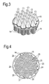
- Figure 3 shows in perspective view the main tube sheet 7 carrying the clusters 14 and the tapering ducts 16.
- the main tube sheet 7 comprises a circular outer rim 23 and a plurality of hexagonal openings 24 bordered by hexagonal rims 25.
- the hexagonal openings 24 are arranged side by side in a dense packing to form a honeycomb structure.
- Spaces 26 between the hexagonal rims and the outer circular rim 23 are closed off, e.g., by a sheet metal.
- Each cluster 14 is carried by a hexagonal secondary tube sheet 30.
- the secondary tube sheet 30 rests on a hexagonal rim 25 of the main tube sheet 7 and comprises openings 31 for carrying the individual tubular filter elements 15.
- the openings 31 are arranged in a hexagonal pattern. This way the tubular filter elements 15 form hexagonal clusters 14 with adjacent clusters 14 having parallel adjacent side faces 29.
- the openings 31 are circular. Other configurations can be used as well, if so desired.
Landscapes
- Physics & Mathematics (AREA)
- Geometry (AREA)
- Chemical & Material Sciences (AREA)
- Chemical Kinetics & Catalysis (AREA)
- Filtering Of Dispersed Particles In Gases (AREA)
Abstract
Filter assembly (1) comprising a filter house (2) with an inner chamber (6) partitioned by a main tube sheet (7) dividing the inner chamber into an inlet compartment (8) with an inlet (10) and an outlet compartment (9) with an outlet (12). The main tube sheet carries a plurality of clusters (14) of tubular filter elements (15). Each tubular filter element has a tubular body (17) extending between an open end (18) and a closed end (19). Adjacent clusters have adjacent side faces (29) which are parallel in cross section. To this end, the clusters (14) may for instance have a hexagonal cross section.
Description
- The invention pertains to a filter assembly, comprising a filter house with an inner chamber partitioned by a tube sheet separating an inlet compartment with an inlet and an outlet compartment with a filtrate outlet, wherein the main tube sheet carries a plurality of clusters of tubular filter elements defining a flow path from the inlet compartment to the outlet compartment, such as candle filters. The tubular filter elements typically have a tubular body of a porous structure extending between an open end and a closed end. The invention also relates to the use of such filter assemblies, for instance for the removal of fine ash or slag particles from a gaseous medium, such as an outlet stream of gasification reactor before the gas enters downstream processing units. Fly ash and slag particles are retained by the wall of the filter element.
- Filter assemblies of this kind can be cleaned by a reverse back flow induced by a pulse of an inert gas. To this end the clusters can be capped with a tapering duct extending between a large end enclosing the open ends of the filter elements of the corresponding cluster, and a smaller open end extending into the outlet compartment. At a distance from each of the open ends of the tapering ducts, a blaster is directed to the open end of the corresponding tapering duct. The blaster can blast a pulse of an inert cleaning gas, such as nitrogen, into the tapering duct. Due to the pressure fall in the tapering duct, the high pressure pulse of cleaning gas causes filtered syngas to enter the duct, creating a pressure wave through the filter elements which results in a temporary reverse flow through the filter elements. This dislodges solids from the filter elements. The dislodged solids drop down to the bottom of the filter house.
- The recovered fly ash and slag particles can either be recycled to the gasifier or discharged as a by-product.
- To provide a high filter capacity in a plant a plurality of filter units is typically used in a parallel arrangement. This results in increased control complexity and significant additional expenditure of the system as a whole.
- It is an object of the invention to reduce the need to use a plurality of filter assemblies in parallel arrangement.
- To this end a filter assembly is disclosed comprising a filter house with an inner chamber partitioned by a main tube sheet dividing the inner chamber into an inlet compartment with an inlet and an outlet compartment with a filtrate outlet. The main tube sheet carries a plurality of clusters of tubular filter elements defining a flow path from the inlet compartment to the outlet compartment. Each tubular filter element has a tubular body extending between an open end and a closed end. In cross section adjacent clusters have parallel adjacent side faces. In this context, the expressions "cross section" and "cross sectional" refer to the cross section along a plane perpendicular to a longitudinal axis of the filter elements.
- It has been found that such an arrangement of filter elements enables a substantial increase of the filter capacity of the clusters relative to their size. A higher density of filter elements can be realized without changing the centre-to-centre distance between the clusters or the centre-to-centre distance between the filter elements. In particular cases this may avoid the need for an auxiliary second filter assembly in parallel arrangement.
- The clusters can for example have a polygonal cross section, e.g., a triangular, square or hexagonal cross section. The use of cluster with a polygonal cross section allows dense packing of the clusters within the filter assembly. Additionally, given a certain centre-to-centre distance and diameter of the filter elements, more filters can be packed within a polygonal cluster than in a cluster of a different outline, in particular a circular outline. Both effects contribute to maximization of the number of filter elements carried by a single main tube sheet, particularly a circular main tube sheet. Hence, the ratio between the number of filter elements and the required diameter of the main tube sheet increases, resulting in a reduction of the required size of the filter house or pressure vessel.
- To enable cleaning by a reverse back flow through the filter elements, the clusters can for instance be capped with a tapering duct extending between a large end enclosing the open ends of the filter elements of the corresponding cluster, and a smaller open end extending into the outlet compartment, wherein at a distance from each of the open ends of the tapering ducts, a blaster is directed to the open end of the corresponding tapering duct. The larger open ends of the tapering ducts can have an outline corresponding to the cross sectional shape of the corresponding clusters. For instance, the larger open ends of the tapering ducts and the clusters can have concentric polygonal, e.g., hexagonal outlines. In an exemplary embodiment, the cross sectional outline of the tapering ducts gradually changes from hexagonal at the larger end to cylindrical at the smaller top ends.
- The main tube sheet can be provided with openings, wherein a secondary tube sheet carrying a cluster of tubular filter elements is suspended in each of said openings. This allows installing and removal of the clusters as subassemblies, allowing easier maintenance outside the filter vessel. The secondary tube sheets, the openings in the main tube sheet, and the clusters may have concentric polygonal, e.g., hexagonal outlines.
- In a specific embodiment, all clusters are equally sized and shaped. In case of hexagonal clusters, this results in a regular honeycomb structure.
- In a specific embodiment, each cluster may for example comprise more than 50 filter elements per m2. In a further specific embodiment, the filter elements within the clusters can be equally sized and equidistantly arranged with a centre-to-centre distance of at least 1,5 times the filter element diameter. For example, the centre-to-centre distance can be at least 100 mm.
- The filter assembly may comprise any suitable number of clusters. In a specific embodiment, e.g. for a filter assembly for filtering synthetic gas discharged by a gasifier, may comprise more than 45 clusters.
- In a further specific embodiment, particularly for a filter assembly for filtering synthetic gas discharged by a gasifier, the filter assembly may be provided with an inlet and a filtrate outlet having a flow capacity of at least 5 m3/sec.
- The width of the gaps between adjacent clusters can for instance be about 200 mm or less. Larger gaps can also be used if so desired.
- The filter elements comprise a tubular wall, e.g., of a porous material, which may for instance be ceramic and/or metallic.
- The tubular body of the filter element typically extends between an open end in open communication with the outlet compartment, and a closed end extending into the inlet compartment. The open end of the filter element can be connected to the tube sheet in line with one of the openings. The opposite end of the filter is closed. The filter elements will generally have a circular cross section. Optionally, the filter elements may have a polygonal cross section, such as a triangular, square or hexagonal cross section, to enable dense packing of the filter elements.
- The disclosed filter assemblies are particularly suitable for filtering syngas formed by the partial combustion of a carbonaceous feed, such as oil, carbon or biomass.
- Exemplary embodiments will be further described with reference to the accompanying drawings. In the drawings:
- Figure 1:
- shows schematically a longitudinal cross section of an exemplary embodiment of a filter assembly;
- Figure 2:
- shows schematically a longitudinal cross section of a cluster of filter elements of the assembly in
Figure 1 ; - Figure 3:
- shows in perspective view a main tube sheet carrying clusters of filter elements of the filter assembly of
Figure 1 ; - Figure 4:
- shows the main tube sheet of
Figure 3 in bottom view. -
Figure 1 shows afilter assembly 1 in a longitudinal cross section. Thefilter assembly 1 comprises afilter house 2, typically formed of acylindrical body 3 capped with a semispherical top 4. The shown embodiment comprises a conicallower section 5 narrowing down in downward direction. - The
filter house 2 encloses aninner chamber 6 partitioned by amain tube sheet 7 which divides theinner chamber 6 into an inlet compartment 8 and an outlet compartment 9. The inlet compartment 8 is provided with aninlet 10 for dust loaded gas, and anoutlet 11 for filtered dust. The outlet compartment 9 is provided with anoutlet 12 for filtered gas. - The
main tube sheet 7 rests on ashoulder 13 at the inside of thefilter house 2. Themain tube sheet 7 carries a plurality ofclusters 14 oftubular filter elements 15. Eachcluster 14 is capped with a taperingduct 16. Asingle cluster 14 with a taperingduct 16 is shown schematically inFigure 2 . - Each
tubular filter element 15 has atubular body 17 with anopen end 18 in open communication with the outlet compartment 9, and aclosed end 19 extending into the inlet compartment 8.Such filter elements 15 are generally referred to as candle filters. The open ends 18 of thefilter elements 15 are located at the level of themain tube sheet 7. - The tapering
duct 16 comprises alarger end 20 enclosing the open ends 18 of thefilter elements 15 of the correspondingcluster 14, and a smalleropen end 21 extending into the outlet compartment 9. - Referring back to
Figure 1 ,blasters 22 are directed to the smaller open ends 21 at a distance above these smaller open ends 21 of the taperingducts 16. - In use, dust loaded gas flows into the inlet compartment 8 of the
filter assembly 1 viainlet 10 in the direction of arrow A. In the inlet compartment 8 theinlet 10 is provided with a downwardly pointing end piece, which is coaxially arranged in relation to thefilter house 2. This way the heavier dust particles tend to swirl down towards thedust outlet 11 in the direction of arrow B, while the rest of the dust loaded gas flows upwardly via thefilter elements 15 and the taperingducts 16 into the outlet compartment 9 (arrows C). The filtered gas is discharged via gas outlet 12 (arrow D). The filter elements filter the passing gas and retain solid contaminants. - The
filter elements 15 can be cleaned by a back flow. To this end, theblasters 22 can blast a cleaning gas via the taperedducts 16 into thefilter elements 15 in a direction opposite to arrows C. The cleaning gas is forced to pass the walls of thefilter elements 15, blowing away the retained fly ash particles which subsequently fall down to be discharged via thedust outlet 11. -
Figure 3 shows in perspective view themain tube sheet 7 carrying theclusters 14 and the taperingducts 16. Referring toFigure 4 , themain tube sheet 7 comprises a circularouter rim 23 and a plurality ofhexagonal openings 24 bordered byhexagonal rims 25. Thehexagonal openings 24 are arranged side by side in a dense packing to form a honeycomb structure.Spaces 26 between the hexagonal rims and the outercircular rim 23 are closed off, e.g., by a sheet metal. - Each
cluster 14 is carried by a hexagonalsecondary tube sheet 30. Thesecondary tube sheet 30 rests on ahexagonal rim 25 of themain tube sheet 7 and comprisesopenings 31 for carrying the individualtubular filter elements 15. Theopenings 31 are arranged in a hexagonal pattern. This way thetubular filter elements 15 formhexagonal clusters 14 withadjacent clusters 14 having parallel adjacent side faces 29. - In the shown exemplary embodiment the
openings 31 are circular. Other configurations can be used as well, if so desired.
Claims (13)
- Filter assembly (1) comprising a filter house (2) with an inner chamber (6) partitioned by a main tube sheet (7) dividing the inner chamber into an inlet compartment (8) with an inlet (10) and an outlet compartment (9) with an outlet (12),- wherein the main tube sheet carries a plurality of clusters (14) of tubular filter elements (15) defining a flow path from the inlet compartment to the outlet compartment,- each tubular filter element having a tubular body (17) extending between an open end (18) and a closed end (19),- wherein adjacent clusters have adjacent side faces (29) which are parallel in cross section.
- A filter assembly according to claim 1 wherein at least a part of the clusters (14) have a hexagonal cross section.
- A filter assembly according to any one of the preceding claims wherein each cluster (14) is capped with a tapering duct (16) extending between a large end (20) enclosing the open ends of the filter elements of the corresponding cluster, and a smaller open end (21) extending into the outlet compartment; and wherein at a distance from each of the open ends of the tapering ducts, a blaster (22) is directed to the open end of the corresponding tapering duct.
- A filter assembly according to claim 3 wherein the larger open ends of the tapering ducts (16) have an outline corresponding to the cross sectional shape of the corresponding clusters (14).
- A filter assembly according to any one of the preceding claims wherein the main tube sheet (7) is provided with openings (24), wherein a secondary tube sheet (30) carrying a cluster (14) of tubular filter elements (15) is suspended in each of said openings.
- A filter assembly according to claim 5, wherein the openings in the main tube sheet (7), the secondary tube sheets (30) and the clusters (14) have concentric hexagonal outlines.
- Filter assembly according to any one of the preceding claims wherein all clusters (14) are equally sized and shaped.
- Filter assembly according to any one of the preceding claims wherein each cluster (14) comprises more than 50 filter elements per m2.
- Filter assembly according to any one of the preceding claims wherein the filter elements (15) within at least one of the clusters are equally sized and equidistantly arranged with a centre-to-centre distance of at least 1,5 times the filter element diameter.
- Filter assembly according to claim 9 wherein the centre-to-centre distance is at least 100 mm.
- Filter assembly according to any one of the preceding claims and comprising more than 45 clusters (14).
- Filter assembly according to any one of the preceding claims wherein the width of the gaps between the facing side faces (29) of adjacent clusters (14) is constant and is 200 mm or less.
- Process for filtering syngas formed by the partial combustion of a carbonaceous feed, using a filter assembly according to any one of the preceding claims.
Priority Applications (1)
| Application Number | Priority Date | Filing Date | Title |
|---|---|---|---|
| EP12169749.4A EP2668991A1 (en) | 2012-05-29 | 2012-05-29 | Filter assembly and process for filtering syngas |
Applications Claiming Priority (1)
| Application Number | Priority Date | Filing Date | Title |
|---|---|---|---|
| EP12169749.4A EP2668991A1 (en) | 2012-05-29 | 2012-05-29 | Filter assembly and process for filtering syngas |
Publications (1)
| Publication Number | Publication Date |
|---|---|
| EP2668991A1 true EP2668991A1 (en) | 2013-12-04 |
Family
ID=46149313
Family Applications (1)
| Application Number | Title | Priority Date | Filing Date |
|---|---|---|---|
| EP12169749.4A Withdrawn EP2668991A1 (en) | 2012-05-29 | 2012-05-29 | Filter assembly and process for filtering syngas |
Country Status (1)
| Country | Link |
|---|---|
| EP (1) | EP2668991A1 (en) |
Citations (2)
| Publication number | Priority date | Publication date | Assignee | Title |
|---|---|---|---|---|
| WO1993020924A1 (en) * | 1992-04-16 | 1993-10-28 | Schumacher Umwelt- Und Trenntechnik Gmbh | Device for the uniform distribution of a two-phase stream |
| US20080271607A1 (en) * | 2007-05-03 | 2008-11-06 | Mott Corporation | Plenum based high pressure blowback gas delivery system in a continuous process flow filtration system |
-
2012
- 2012-05-29 EP EP12169749.4A patent/EP2668991A1/en not_active Withdrawn
Patent Citations (2)
| Publication number | Priority date | Publication date | Assignee | Title |
|---|---|---|---|---|
| WO1993020924A1 (en) * | 1992-04-16 | 1993-10-28 | Schumacher Umwelt- Und Trenntechnik Gmbh | Device for the uniform distribution of a two-phase stream |
| US20080271607A1 (en) * | 2007-05-03 | 2008-11-06 | Mott Corporation | Plenum based high pressure blowback gas delivery system in a continuous process flow filtration system |
Similar Documents
| Publication | Publication Date | Title |
|---|---|---|
| US8945283B1 (en) | Apparatuses and methods for gas-solid separations using cyclones | |
| CA2063605C (en) | Apparatus and a method for separating particulate material from high-temperature gases | |
| KR101688467B1 (en) | Cyclone Bag-filter Dust Collecter with Diffuser | |
| US10328407B2 (en) | Particle separating catalytic chemical reactor and particle separator | |
| US20200001309A1 (en) | Reverse flow cyclones | |
| US4286974A (en) | Compound particle separator | |
| RU2471565C2 (en) | Gases and solids separator | |
| JP4344730B2 (en) | Particulate matter removal device | |
| KR20180095072A (en) | Systems and methods for filtering gas-solid mixtures | |
| CN102935428B (en) | A kind of separator of separate solid particles and application thereof | |
| US5458665A (en) | Apparatus for filtering gases | |
| AU2009100485A4 (en) | Uniflow cyclone components for improving particulate separation and equipment life | |
| KR20150110521A (en) | Dust catcher for blast furnace gas | |
| EP2411115B1 (en) | Vessel for removing solid particles from gases | |
| WO1996018450A1 (en) | Separation of particulate from flue gas of fossil fuel combustion and gasification | |
| CN201333367Y (en) | Complex fly ash filter with cyclone inside for pre dust removal | |
| US9168499B1 (en) | Arrangements for removing entrained catalyst particulates from a gas | |
| LT5912B (en) | Multi-cyclone | |
| CN105148672A (en) | Combined type dust remover used for combustible gas | |
| CN101658750B (en) | Composite fly ash filter with built-in cyclone pre-dedusting | |
| US20110030558A1 (en) | Dust collector, filtration arrangment, and methods | |
| CN111068593B (en) | Fluidized bed reactor and method of application thereof, and method for desulfurization of hydrocarbon oil | |
| CN114144251A (en) | System for recovering entrained particles from an exhaust gas stream | |
| RU2178332C1 (en) | Aerosol tubular separator | |
| RU239161U1 (en) | GAS CLEANING CYCLONE |
Legal Events
| Date | Code | Title | Description |
|---|---|---|---|
| PUAI | Public reference made under article 153(3) epc to a published international application that has entered the european phase |
Free format text: ORIGINAL CODE: 0009012 |
|
| AK | Designated contracting states |
Kind code of ref document: A1 Designated state(s): AL AT BE BG CH CY CZ DE DK EE ES FI FR GB GR HR HU IE IS IT LI LT LU LV MC MK MT NL NO PL PT RO RS SE SI SK SM TR |
|
| AX | Request for extension of the european patent |
Extension state: BA ME |
|
| STAA | Information on the status of an ep patent application or granted ep patent |
Free format text: STATUS: THE APPLICATION IS DEEMED TO BE WITHDRAWN |
|
| 18D | Application deemed to be withdrawn |
Effective date: 20140605 |