EP2668691B1 - Manifold assembly for controlling gas flow and flow distribution in a fuel cell stack - Google Patents
Manifold assembly for controlling gas flow and flow distribution in a fuel cell stack Download PDFInfo
- Publication number
- EP2668691B1 EP2668691B1 EP12739776.8A EP12739776A EP2668691B1 EP 2668691 B1 EP2668691 B1 EP 2668691B1 EP 12739776 A EP12739776 A EP 12739776A EP 2668691 B1 EP2668691 B1 EP 2668691B1
- Authority
- EP
- European Patent Office
- Prior art keywords
- fuel cell
- manifold
- anode
- cell stack
- stack
- Prior art date
- Legal status (The legal status is an assumption and is not a legal conclusion. Google has not performed a legal analysis and makes no representation as to the accuracy of the status listed.)
- Active
Links
Images



Classifications
-
- H—ELECTRICITY
- H01—ELECTRIC ELEMENTS
- H01M—PROCESSES OR MEANS, e.g. BATTERIES, FOR THE DIRECT CONVERSION OF CHEMICAL ENERGY INTO ELECTRICAL ENERGY
- H01M8/00—Fuel cells; Manufacture thereof
- H01M8/04—Auxiliary arrangements, e.g. for control of pressure or for circulation of fluids
- H01M8/04082—Arrangements for control of reactant parameters, e.g. pressure or concentration
- H01M8/04089—Arrangements for control of reactant parameters, e.g. pressure or concentration of gaseous reactants
-
- H—ELECTRICITY
- H01—ELECTRIC ELEMENTS
- H01M—PROCESSES OR MEANS, e.g. BATTERIES, FOR THE DIRECT CONVERSION OF CHEMICAL ENERGY INTO ELECTRICAL ENERGY
- H01M8/00—Fuel cells; Manufacture thereof
- H01M8/04—Auxiliary arrangements, e.g. for control of pressure or for circulation of fluids
- H01M8/04276—Arrangements for managing the electrolyte stream, e.g. heat exchange
-
- H—ELECTRICITY
- H01—ELECTRIC ELEMENTS
- H01M—PROCESSES OR MEANS, e.g. BATTERIES, FOR THE DIRECT CONVERSION OF CHEMICAL ENERGY INTO ELECTRICAL ENERGY
- H01M8/00—Fuel cells; Manufacture thereof
- H01M8/02—Details
- H01M8/0289—Means for holding the electrolyte
-
- H—ELECTRICITY
- H01—ELECTRIC ELEMENTS
- H01M—PROCESSES OR MEANS, e.g. BATTERIES, FOR THE DIRECT CONVERSION OF CHEMICAL ENERGY INTO ELECTRICAL ENERGY
- H01M8/00—Fuel cells; Manufacture thereof
- H01M8/04—Auxiliary arrangements, e.g. for control of pressure or for circulation of fluids
- H01M8/04082—Arrangements for control of reactant parameters, e.g. pressure or concentration
-
- H—ELECTRICITY
- H01—ELECTRIC ELEMENTS
- H01M—PROCESSES OR MEANS, e.g. BATTERIES, FOR THE DIRECT CONVERSION OF CHEMICAL ENERGY INTO ELECTRICAL ENERGY
- H01M8/00—Fuel cells; Manufacture thereof
- H01M8/24—Grouping of fuel cells, e.g. stacking of fuel cells
- H01M8/2465—Details of groupings of fuel cells
- H01M8/2484—Details of groupings of fuel cells characterised by external manifolds
-
- Y—GENERAL TAGGING OF NEW TECHNOLOGICAL DEVELOPMENTS; GENERAL TAGGING OF CROSS-SECTIONAL TECHNOLOGIES SPANNING OVER SEVERAL SECTIONS OF THE IPC; TECHNICAL SUBJECTS COVERED BY FORMER USPC CROSS-REFERENCE ART COLLECTIONS [XRACs] AND DIGESTS
- Y02—TECHNOLOGIES OR APPLICATIONS FOR MITIGATION OR ADAPTATION AGAINST CLIMATE CHANGE
- Y02E—REDUCTION OF GREENHOUSE GAS [GHG] EMISSIONS, RELATED TO ENERGY GENERATION, TRANSMISSION OR DISTRIBUTION
- Y02E60/00—Enabling technologies; Technologies with a potential or indirect contribution to GHG emissions mitigation
- Y02E60/30—Hydrogen technology
- Y02E60/50—Fuel cells
Definitions
- This invention relates to fuel cell systems with at least one fuel cell stack and an external manifold and, in particular, to a manifold assembly or a flow distribution control assembly for use in a fuel cell system having at least one externally manifolded fuel cell stack.
- the invention comprises an assembly that includes one or more baffle plates disposed in one or more of the manifolds of the fuel cell stack for controlling the flow distribution of the gases among multiple fuel cells of the stack.
- Variations of the baffling principal can be applied at a system level to regulate gas flow to a fuel system that includes two or more fuel cell stacks.
- the system level baffling assembly comprises one or more baffle plates in an intake assembly and/or in an exhaust assembly of the multiple fuel cell system so that each fuel cell stack in the system receives a predetermined amount of gas flow.
- a fuel cell is a device that directly converts chemical energy in the form of a fuel into electrical energy by way of an electrochemical reaction.
- a fuel cell like a battery, a fuel cell includes a negative electrode or anode and a positive electrode or cathode separated by an electrolyte that serves to conduct electrically charged ions between them.
- a fuel cell will continue to produce electric power as long as fuel and oxidant are supplied to the anode and cathode, respectively.
- a fuel cell stack may be categorized as an internally manifolded stack or an externally manifolded stack.
- gas passages for delivering fuel and oxidant are built into the fuel cell plates themselves.
- the fuel cell plates are left open on their ends and gas is delivered by way of manifolds or pans sealed to the respective faces of the fuel cell stack.
- the manifolds provide sealed passages for delivering fuel and oxidant gases to the fuel cells and preventing those gases from leaking either to the environment or to the other manifolds.
- the stack is placed in an enclosure and the enclosure environment represents one of the process gases.
- the enclosure environment represents one of the process gases.
- at least three manifolds are required to provide inlet and outlet gas passages for the stack, each of which must be sealed to the stack.
- the manifolds must perform the above functions under the conditions required for operation of the fuel cell stack and for the duration of its life.
- An important aspect of the performance of an externally manifolded fuel cell stack is the flow distribution of process gases, i.e. fuel and oxidant process gases, among multiple fuel cells so that the process gases are evenly distributed to each of the fuel cells in the stack.
- process gases i.e. fuel and oxidant process gases
- all of the fuel cells in the stack get about the same amount of gas flow therethrough for the electrochemical reaction and for the purpose of cooling the cells uniformly or in predetermined regions.
- fuel cells that are disposed closest to the anode exhaust pipe receive more fuel gas flow than fuel cells disposed further away from the exhaust pipe.
- the fuel cells with less gas flow therethrough are subjected to greater overheating while fuel cells with more gas flow produce more electrochemical reactions and thus, more power. This uneven gas distribution leads to a decreased fuel cell stack lifespan.
- an externally manifolded fuel cell stack for a greater control of the flow distribution of the gases to the fuel cells in the stack to more uniformly distribute the gas flow to all of the fuel cells in the stack.
- controlling of the fuel gas supply to individual fuel cells within the stack requires a complex piping and fuel delivery assembly.
- controlling the distribution of fuel so as to provide cooling to the anode inlet area of the stack.
- an object of the present invention to provide a manifold assembly that is capable of controlling the gas flow distribution through the fuel cells in the stack.
- the fuel cell system may include multiple fuel cell stacks that operate from a single fuel source provided by a fuel intake assembly and/or a single oxidant source provided by an oxidant gas intake assembly and/or exhaust spent gas into a single exhaust assembly.
- each stack requires a predetermined amount of fuel and/or a predetermined percentage of the fuel in air.
- flow control valves are costly and fragile in the hot, corrosive environments that surround the fuel cell stacks, it is desirable to have a flow control assembly that does not depend on such costly, fragile valves.
- a manifold assembly for use with a fuel cell stack, the manifold assembly comprising an external manifold for abutting and sealingly enclosing a face of the fuel cell stack, wherein the manifold comprises an enclosure for one of: providing inlet gas to the fuel cell stack and receiving exhaust gas from said fuel cell stack; and one or more baffles disposed in the enclosure of the external manifold.
- the one or more baffles one of: (a) controls gas flow distribution of the inlet gas from said enclosure to fuel cells of said fuel cell stack; and (b) controls direction of the exhaust gas flow within the enclosure.
- the external manifold is an anode exhaust manifold for receiving anode exhaust gas from an anode outlet face of said fuel cell stack
- the enclosure of the manifold includes an opening adapted to face the anode outlet face of the fuel cell stack and through which anode exhaust gas is output from the anode outlet face into the enclosure when the manifold abuts the anode outlet face.
- a height of the enclosure of the manifold is at least equal to or greater than a height of the fuel cell stack and the manifold assembly includes a plurality of baffles that are disposed in the enclosure along at least a portion of the enclosure's height.
- the baffles are disposed in the enclosure so as to control back pressure of the anode exhaust in predetermined fuel cells of the fuel cell stack and to reduce the amount of inlet fuel flow into the predetermined fuel cells.
- the predetermined fuel cells of the fuel cell stack include fuel cells that are closest to the exhaust outlet in the enclosure of the manifold and fuel cells that receive greater inlet fuel flow than other fuel cells in the fuel cell stack when the fuel cell stack is used with another manifold assembly without the baffles.
- the enclosure of the manifold includes an outer wall opposing the opening, opposing top and bottom walls connected to the outer wall and first and second opposing sidewalls connected to the outer wall and to the top and bottom walls.
- Each of the baffles includes first and second opposing ends that are coupled with the first and second sidewalls of the enclosure, respectively, and the baffles are successively disposed along a portion of the height of the enclosure with successive baffles being separated by a vent.
- each of the baffles is curved toward the outer wall of the enclosure so that the baffles are concave with respect to the anode outlet face of the fuel cell stack when the manifold assembly abuts the anode outlet face.
- One or more support members may be used to support the baffles in the enclosure, and the support member(s) may be coupled to one of the top or bottom walls or to one or both of the sidewalls.
- one or more of the baffles may include a vent, a perforation and/or an opening therein at one or more predetermined locations.
- the external manifold is a cathode inlet manifold for enclosing a cathode inlet face of the fuel cell stack and for providing oxidant gas to the cathode inlet face.
- at least one baffle controls gas flow distribution of the inlet oxidant gas from the enclosure to the fuel cells in the fuel cell stack so that portions of the fuel cells closest to an anode inlet face of the fuel cell stack receive increased flow of inlet oxidant gas when the manifold assembly abuts the cathode inlet face.
- the enclosure includes an outer wall, opposing top and bottom walls connected to the outer wall and opposing first and second sidewalls connected to the outer wall and to the top and bottom walls, with the first sidewall of the enclosure being disposed closest to an anode inlet face of the stack when the manifold assembly abuts the cathode inlet face of the stack.
- the at least one baffle in such embodiments extends along a portion of a width of the enclosure from the second sidewall of the enclosure in the direction of the first sidewall.
- the baffle may be substantially flat or may be curved, depending on the stack requirements.
- a fuel cell assembly with the manifold assemblies described above, and a method of controlling the flow distribution of gas are also described.
- fuel cell systems with multiple fuel cell stacks housed in an enclosure and one or more baffles for controlling the gas flow at the system level are also described.
- the present invention provides a manifold assembly for use in a fuel cell system which controls gas flow distribution through a fuel cell stack of the system so as to achieve more uniform gas flow distribution through each fuel cell in the stack and to provide cooling to desired areas of the stack, such as the anode inlet area of the stack.
- FIGS. 1-3C show illustrative embodiments of an anode manifold assembly 100 for use in the fuel cell system and for controlling the gas flow distribution through the fuel cell stack.
- the anode manifold assembly 100 shown in FIGS. 1-3C is used with, or as part of, a fuel cell stack that comprises a plurality of stacked fuel cells and, in some cases, hundreds of stacked fuel cells.
- the fuel cell stack includes anode inlet and outlet faces for receiving and outputting, respectively, fuel gas and anode exhaust, and cathode inlet and outlet faces for receiving and outputting, respectively, oxidant gas and cathode exhaust.
- Each of the cathode inlet, anode inlet and anode outlet faces of the stack are typically enclosed by a manifold or a manifold assembly, so that oxidant gas and fuel gas are delivered through the respective manifolds abutting the cathode inlet and anode inlet faces, respectively, and anode exhaust is output into the manifold abutting the anode outlet face.
- the anode manifold assembly 100 of FIGS. 1-3C is adapted to sealingly abut the anode outlet face of the fuel cell stack and to receive anode exhaust gas output by the stack.
- each fuel cell is fed with an individual gas flow control assembly, such as a valve, for controlling the amount of gas supplied to the individual fuel cell. Therefore, the whole fuel cell stack is fed with the fuel and oxidant gases, respectively, as a unit, with the fuel being supplied to the whole stack from the anode inlet manifold and the oxidant being supplied to the whole stack from the cathode inlet manifold.
- the anode outlet manifold such as the anode manifold assembly 100 of FIGS. 1-3C , receives the anode exhaust from the entire stack, and thereafter outputs the received anode exhaust for processing or for venting to the outside through an exhaust outlet.
- each fuel cell in the stack receives about the same amount of fuel and oxidant gases. Since, as discussed above, those fuel cells closest to the exhaust outlet receive the most gas flow and the fuel cells furthest from the exhaust outlet receive less gas flow, a flow regulation device or assembly is needed for regulating the gas flow, particularly the fuel flow, so that each fuel cell receives the same amount of gas flow regardless of its distance from the exhaust outlet.
- the anode manifold assembly of FIGS. 1-3C includes such a flow regulation assembly and is capable of adjusting the flow of fuel through the fuel cell stack so that the fuel flow is evenly distributed among the fuel cells in the stack.
- the anode manifold assembly 100 includes an external anode exhaust manifold 102 which, when used with the fuel cell stack, abuts the anode outlet face of the stack.
- the anode exhaust manifold 102 includes an exhaust outlet 104 disposed at one end 102a of the manifold 102, and one or more baffles 106 disposed adjacent to, or near, the end 102a of the manifold 102.
- the anode manifold 102 forms a compartment or an enclosure for enclosing the anode outlet face of the fuel cell stack and for receiving the anode exhaust gas from the fuel cell stack, and the enclosure has an opening through which the anode exhaust is received from the anode outlet face.
- An illustrative configuration of the anode manifold 102 is disclosed in U.S. Patent no. 6,877,611 , assigned to the same assignee herein.
- the manifold 102 includes an outer wall 102c which opposes the opening in the manifold, opposing top and bottom walls coupled to the outer wall 102c and opposing side walls coupled with the outer wall and the top and bottom walls. Outer ends of the top and bottom walls and of the sidewalls form an abutting surface 102d of the manifold that abuts the anode outlet face of the stack.
- the exhaust outlet 104 in the embodiment shown in FIGS. 1-3C is formed in the outer wall 102c and is disposed near an end 102a of the manifold 102 which abuts the positive end or the negative end of the fuel cell stack. However, in other embodiments, the exhaust outlet 104 may be disposed in any other area of the manifold.
- the one or more baffles 106 are arranged in the anode exhaust manifold 102 within the space between the outer wall 102c of the manifold 102 and the abutting surface 102d of the manifold 102 which is adapted to abut the anode exhaust face of the fuel cell stack.
- the one or more baffles 106 are disposed near the exhaust outlet 104 pipe in the outer wall 102c of the manifold 102.
- the one or more baffles 106 are strategically disposed in or near the regions of the manifold where there is greater gas flow, which is typically near the exhaust outlet 104.
- the baffles are disposed in the enclosure of the manifold so as to control back pressure of the anode exhaust gas output from predetermined fuel cells of the fuel cell stack and to reduce the amount of inlet fuel flow into these predetermined fuel cells.
- the predetermined fuel cells of the stack include fuel cells that are closest to the exhaust outlet in the manifold and fuel cell receiving greater inlet fuel flow than other fuel cells in the stack when the stack is used with a conventional manifold that does not include baffles.
- the one or more baffles 106 extend along a portion of the height of the manifold 102. However, in some embodiments, depending on the configuration of the manifold 102 and the number of and location of the exhaust outlet 104, the one or more baffles 106 may extend along the entire height of the manifold 102.
- the baffles 106 are formed from one or more stainless steel sheets. However, other materials which have similar thermal expansion coefficients to that of the manifold and which have sufficient strength at high temperature may be used for the baffles.
- FIGS. 1-3C include several baffles 106 disposed successively in the enclosure of the manifold along at least a portion of the height of the manifold with vents or spaces 107 between adjacent or successive baffles 106.
- the vents 107 between adjacent baffles 106 are provided in the areas of the manifold where more flow is needed, so as to effectively control of the gas flow through the fuel cell stack.
- the baffles may also include vents, perforations or openings in the baffles themselves, which are provided at predetermined locations where additional flow is needed, so as to further control the gas flow through the fuel cell stack.
- FIGS. 1 and 2 show the illustrative embodiments of the anode outlet manifold assembly which include three or four baffles 106 of varying sizes disposed in the manifold 102 near the exhaust pipe that forms the exhaust outlet 104.
- the anode outlet manifold assembly includes first, second and third baffles 106a-c
- the anode outlet manifold assembly includes first, second, third and fourth baffles 106a-d, with the first, second and third baffles 106a-c having the same or similar configuration as the baffles 106a-c of FIG. 1 .
- FIGS. 1 show the illustrative embodiments of the anode outlet manifold assembly which include three or four baffles 106 of varying sizes disposed in the manifold 102 near the exhaust pipe that forms the exhaust outlet 104.
- the anode outlet manifold assembly includes first, second and third baffles 106a-c
- the anode outlet manifold assembly includes first, second, third and fourth
- each of the baffles 106a-c or 106a-d is positioned in the manifold so that it extends across the width of the manifold 102, from one sidewall to the other sidewall.
- each baffle includes two opposing ends which are coupled to the opposing sidewalls of the manifold.
- opposing ends of each baffle are connected to the respective sides of the manifold, within the manifold 102.
- each of the baffles 106a-d has at least a slight curvature thereto, curving toward the outer wall of the manifold, so that the baffles are concave with respect to the fuel cell stack face.
- curved baffle structures are desired because they warp in a predictable manner during high-temperature operation, and do not interfere with other machine structures.
- flat or convex baffles may be used.
- a support structure or rib 108 may be included for supporting the baffles within the manifold 102.
- the support structure 108 extends from the end 102a of the manifold along the central areas of the baffles 106 and is connected to the manifold-side surfaces of the baffles 106 so as to provide support for the baffles 106.
- the attachment line of the support rib 108 is shown in FIG. 2 by a broken line 205c.
- the support rib may be coupled to one of the top and bottom walls of the manifold.
- the illustrative embodiments shown include only one support structure 108, in other embodiments, additional support structures may be used, or no support structure may be used, depending on the size of the baffles and the manifold requirements. Also, in some embodiments, the support rib may be attached to other areas of the manifold and/or may be attached to the fuel cell side surface of the baffles instead of the manifold-side surfaces.
- the baffles 106a-d are installed in the compartment or enclosure formed by the manifold between the outer wall 102a of the manifold and the stack-abutting face 102d of the manifold.
- the baffles 106a-d are connected to the sidewalls of the manifold at a predetermined distance from the sidewall ends that form the stack-abutting face 102d of the manifold. The predetermined distance is such that the baffles 106a-d do not create excessive pressure at the anode outlet face of the stack and so that only a minor pressure penalty is incurred by the use of the baffles in the manifold 102.
- the predetermined distance from the sidewall ends abutting the anode outlet stack face to the point of connection of the baffles to the manifold sidewalls is 1 inch.
- the predetermined distance may vary depending on the depth of the manifold and the size of the fuel cell stack.
- the first baffle 106a is disposed at or near the outlet end 102a of the manifold and has a smaller height than the second and third 106b, 106c baffles.
- the second baffle 106b is positioned adjacent the first baffle 106a with a slot or a vent 107a formed therebetween, and the third baffle 106c is positioned adjacent the second baffle 106b with a slot or a vent 107b therebetween.
- the heights of the second and third baffles 106b, 106c are greater than that of the first baffle 106a and of the fourth baffle 106d because the second baffle 106b is disposed directly opposite, or facing, the exhaust outlet 104 and the third baffle 106c is disposed near the exhaust outlet 104, and correspond to the locations of the fuel cell stack which typically receive greater gas flow.
- Such positioning of the second and third baffles 106b and 106c reduces inlet gas flow through the fuel cells corresponding to the locations of the baffles and increases inlet gas flow through fuel cells in other areas of the stack, thereby controlling the gas flow to provide more uniform gas flow throughout the stack.
- the fourth baffle 106d is disposed adjacent the third baffle 106c with a vent or a slot 107c therebetween.
- the height of the fourth baffle 106d in this illustrative embodiment is smaller than the heights of the second and third baffles and is similar to the height of the first baffle 106a.
- the embodiment shown in FIG. 1 does not include the fourth baffle 106d, it is understood that the configuration of the anode outlet manifold assembly of FIG. 1 may be varied so as to include the fourth baffle 106d following the third baffle 106c, similar to the embodiment shown in FIG. 2 .
- FIGS. 4A and 4B show photographs of the baffles 106a-d installed in the enclosure of the manifold 102 of the anode manifold assembly of FIG. 2 .
- the installation of the baffles 106a-d in the anode manifold assembly of FIG. 1 is similar, with the fourth baffle 106d being omitted from the anode manifold assembly of FIG. 1 .
- the first baffle 106a is installed adjacent to the outlet end 102a of the manifold and extends beyond a fixed end plate of the fuel cell stack which the manifold 102 would abut.
- the first baffle is positioned at 4.5 inches outside of the fixed end plate.
- the height of the first baffle is about 7 inches.
- the second baffle 106b is installed at a position adjacent or successive to the first baffle 106a along the height of the stack, about 4 inches from the fixed end plate of the stack that the manifold 102 would abut.
- there is a slot or a vent 107a between the first baffle 106a and the second baffle 106b which has a height of about 1/4 inches.
- the height of the second baffle 106b is about 23.5 inches.
- the third baffle 106c is installed at a position adjacent or successive to the second baffle along the height of the stack and about 28 inches from the fixed end plate of the stack that the manifold 102 would abut.
- the height of the third baffle is about 24.5 inches.
- the fourth baffle 106d is installed at a position adjacent or successive to the third baffle along the height of the stack that is about 52 inches from the fixed end plate of the stack that the manifold would abut, and extends to a position that is about 59 inches from the fixed end plate of the stack.
- the height of the fourth baffle 106d is about 7 inches. There is also provided a vent or a slot 107c between the third and fourth baffles 106c, 106d which has a height of about 1/4 inches.
- the space in the manifold is open to its outer wall 102c without further baffles, and exhaust is free to flow within the manifold to an area between the baffles 106 and the manifold outer wall 102c toward the exhaust outlet 104.
- the baffle arrangement shown in FIGS. 4A and 4B is suitable for anode manifold assemblies used with 300kW fuel cell stack systems, such as DFC®300 manufactured by FuelCell Energy, Inc. However, it is understood that the number of the baffles used in the anode manifold assembly and their arrangement may be varied depending on the dimensions and requirements of the manifold and of the fuel cell system.
- the fuel cell system 200 includes a fuel cell stack 202 that has an anode inlet face 202a adapted to receive fuel gas, an anode outlet face 202b which opposes the anode inlet face 202a and which is adapted to output anode exhaust, a cathode inlet face 202c adapted to receive oxidant gas and a cathode outlet face 202d adapted to output cathode exhaust.
- the fuel cell stack 202 is schematically shown as a porous block, which is formed by the plurality of stacked fuel cells.
- the anode manifold assembly 100 abuts the anode outlet face 202b of the fuel cell stack 202 and has a similar construction to the manifold assembly of FIGS. 4A and 4B , and similar to the manifold assembly of FIG. 1 , with the exception of the added fourth baffle 106d.
- the fuel cell stack 202 may also include an anode inlet manifold abutting the anode inlet face 202a, a cathode inlet manifold abutting the cathode inlet face 202c and in some embodiments a cathode outlet manifold abutting the cathode outlet face 202d.
- the flow of fuel into the fuel cell stack 202 is shown in FIG. 2 by the arrows 205a labeled as "flow in".
- the fuel cell stack 202 receives fuel through the anode inlet face 202a, which is typically delivered via the anode inlet manifold.
- the fuel cells of the stack output anode exhaust, comprising spent fuel gas, through the anode outlet face 202b into the anode manifold assembly 101.
- the flow of anode exhaust from the anode outlet face 202b of the stack is shown using smaller arrows 205b in FIG. 2 .
- the flow of anode exhaust 205b leaving the fuel cells in the area of, or in proximity of, the exhaust outlet 104 is redirected by the baffles 106 of the anode manifold assembly 100 so that the anode exhaust flows around the baffles and/or through the vents 107 between the baffles. That is, the anode exhaust flow from the stack to the exhaust outlet 104 is caused by the baffles 106 to travel over and then under the baffle plates and/or to pass through the strategically placed vents between adjacent or successive baffles. In this way, the baffles 106 restrict the flow of the anode exhaust in the area of the exhaust outlet 104, and reduce the pressure drop across the fuel cells located in the area of, or proximity with, the exhaust outlet 104.
- the pressure drop across the fuel cells in the area of the exhaust outlet 104 is more uniform with the pressure drop across the fuel cells disposed farther away from the exhaust outlet, thereby creating a more uniform distribution of fuel flow through the fuel cells in the stack, independent of how closely or far away the fuel cells are located relative to the exhaust outlet in the manifold.
- the baffles 106 may also have vents, perforations and/or other openings formed in the baffles themselves (not shown) and strategically placed so as to control the flow and direction of the anode exhaust to the exhaust outlet.
- the anode exhaust flow from the stack to the exhaust outlet in the area of the exhaust outlet would also travel through such vents, perforations or openings in the baffles.
- the vents, perforations and/or openings in the baffles provide for additional control of fuel flow and fuel flow distribution through the fuel cell stack.
- FIGS. 3A, 3B and 3C schematically show side, front and top views of the anode manifold assembly 100 abutting the fuel cell stack 200, shown as a porous block.
- the fuel cell stack 200 also includes an inlet manifold 208 through which fuel is supplied to the fuel cell stack 200. The flow of fuel is shown in FIGS. 3A and 3C using arrows 205a.
- the anode manifold assembly 100 includes a plurality of baffles, i.e.
- baffles which are disposed in the area of the exhaust outlet 104 so as to restrict the flow of anode exhaust leaving the fuel cell stack in the area of the exhaust outlet 104, and as a result, control the flow of fuel into the fuel cells of the stack so that the fuel is more uniformly distributed among the fuel cells of the stack.
- FIG. 5 shows a graph of gas flow distribution in fuel cell stacks with conventional anode exhaust manifolds and in fuel cell stacks with the manifold assembly of the present invention, such as the manifold assemblies shown in FIGS. 2 and 4A-4B .
- the X-axis represents stack height percentage, or the position of the fuel cells along the height of the fuel cell stack, while the Y-axis represents the measured flow of fuel through the fuel cells.
- a plot of the fuel flow distribution through the fuel cell stack with a conventional manifold assembly, without any baffles, is labeled as "No Baffle," while plots of the fuel flow distributions through fuel cell stacks that included the anode manifold assembly of the present invention are labeled as "With Baffle.”
- the flow distribution in the conventional fuel cell stacks with conventional manifolds varies from one end of the stack to the other end of the stack, so that the fuel flow is greatest in the area of 0-10% of the stack height, corresponding to the area closest to the anode exhaust outlet, and lowest in the area of 80-100% of the stack height, corresponding to the area furthest away from the anode exhaust outlet.
- the flow distribution of the fuel in the fuel cell stacks that used the anode manifold assembly of the present invention abutting the anode outlet face of the stack was substantially uniform throughout the stack, and varied only slightly from one area to another. It is further noted that the slight variations in the fuel flow distribution may be corrected by using strategically placed vents in the area of 20-30% of the stack height and/or strategically placed additional baffles in the area of 55-75% of the stack height.
- baffles may be employed in other manifold assemblies so as to further control the flow of gases through the fuel cell stack and to control the temperature in the stack.
- one or more baffles may be used in a cathode inlet manifold assembly, which is adapted to abut the cathode inlet face of the stack, in order to control the flow of oxidant gas into the fuel cell stack and to control the temperature in the fuel cell stack.
- the cathode inlet face 202c of the stack is substantially perpendicular to the anode inlet face 202a of the stack, and a portion of the cathode inlet face 202c1 extends along the anode inlet 202a while a portion of the cathode inlet face 202c2 extends along the anode outlet face 202b.
- cooling is needed in the anode inlet region of the stack and uniform cathode exhaust temperatures along the height of the stack are desired.
- Such temperature characteristics may be achieved by controlling the flow of oxidant gas to the fuel cell stack so as to provide greater oxidant flow to the area of the cathode inlet 202c1 that is near the anode inlet portion of the stack.
- This oxidant gas flow control may be achieved by providing one or more baffles in the cathode inlet manifold, and in particular, by positioning the one or more baffles in the cathode inlet manifold so that the area of the cathode inlet face that is adjacent or near the anode inlet of the stack receives greater oxidant flow.
- the one or more baffles are positioned in the cathode inlet manifold in the area of the cathode inlet 202c2 that is near the anode outlet so as to provide an opening in the area of the cathode inlet 202c1 near the anode inlet.
- FIGS. 6A and 6B schematically show the side and top views of the fuel cell stack 200 that includes both the anode manifold assembly 100 of FIGS. 1-4A and a cathode inlet manifold assembly 300 abutting the cathode inlet face 202c of the stack.
- the construction of the anode manifold assembly 100 in this embodiment is the same as in the above-described embodiments, and thus, a description of the anode manifold assembly 100 is omitted.
- the cathode inlet manifold assembly 300 includes a cathode inlet manifold 302 abutting and enclosing the cathode inlet face 202c of the stack 200.
- the cathode inlet manifold 302 forms an enclosure or a compartment for receiving oxidant gas and supplies the oxidant gas to fuel cell cathodes of the fuel cell stack.
- the manifold 302 may have a construction as described in U.S. Pat. No. 6,887,611 , assigned to the same assignee herein.
- the manifold 302 includes an outer wall, opposing top and bottom walls connected to the outer wall and opposing sidewalls 302a, 302b connected to the outer wall and to the top and bottom walls.
- the cathode inlet manifold assembly 300 includes an oxidant inlet 304 and one or more baffles 306 for controlling the flow of oxidant gas from the oxidant inlet 304 through the enclosure of the manifold 302 and to the fuel cell stack.
- the cathode inlet manifold assembly 300 includes one baffle 306 which extends from a first sidewall 302a of the manifold 302, which extends along the fuel outlet side of the stack, and toward the opposing second sidewall 302b of the manifold 302, which extends along the fuel inlet side of the stack.
- the baffle 306 extends only part of the way from the first side 302a to the second side 302b, so as to create an opening 307 along the second side 302b of the manifold enclosure.
- the baffle 306 may be supported using one or more support members 308 which, in FIG. 6A , connect an end of the baffle 306 to the second sidewall 302b of the manifold so as to provide support to the baffle 306.
- oxidant gas supplied to the cathode inlet manifold 302 through the inlet 304 is directed by the baffle 306 to travel along and around the baffle before reaching the fuel cell stack 200. Since the opening 307 extends along the second sidewall of the manifold 302b which is adjacent the fuel inlet side of the stack, more oxidant gas flow is provided to areas of the fuel cells at or near the opening 307. In this way, additional cooling is provided to the fuel inlet area of the fuel cell stack through heat exchange between the oxidant flow through the cathodes near the fuel inlet area of the stack and fuel flow through the inlet area of the anodes.
- FIGS. 6A and 6B other openings or perforations in the baffle may be provided and disposed strategically so as to provide further cooling to other areas of the stack, as needed.
- FIGS. 6A and 6B only includes one baffle 306, multiple baffles may be used so as to provide desired oxidant flow control.
- FIGS. 7A, 7B , and 7C show cathode exhaust and cathode inlet temperature distributions from negative to positive ends of the fuel cell stack which uses the cathode inlet manifold assembly 300 of FIGS. 6A and 6B abutting its cathode inlet face and the anode manifold assembly 100 of FIGS. 2 and 4A-4B abutting its anode outlet face. between In FIGS.
- each group of bars i.e. groups of four bars in FIG. 7A and groups of five bars in FIG. 7B , represents different positions within the stack, extending from a negative end of the stack, i.e. left-most bar in each group, to a positive end of the stack, i.e. right-most bar in each group.
- FIG. 7C shows a comparison between four conventional stacks, i.e. stacks A, B, C, and D, that do not include any baffles in their manifolds, and a fifth stack, i.e. stack E, that has both the anode manifold assembly 100 of FIGS. 2 and 4A-4B and the cathode inlet manifold assembly 300 of FIGS. 6A and 6B .
- the X-axis represents the five different stacks, listed as A, B, C, D, and E
- the Y-axis represents the fuel cell cathode exhaust temperature difference from the lowest or zero percent height fuel cell in the fuel cell stacks.
- each stack A-E includes a measurement of the cathode exhaust temperature difference between the 50% stack height position and the 0% stack height position and a measurement of the cathode exhaust temperature difference between the 75% stack height position and the 0% stack height position.
- the temperature of the cathode exhaust output from the fuel cell stacks tested had a variation of about 10 degrees F from the negative end of the stack to the positive end of the stack at different current densities. This temperature distribution is the opposite of the temperature distribution typically seen in fuel cells that use conventional manifolds without any baffles.
- the highest temperature of the cathode exhaust was typically output from the middle of the fuel cell stack, as shown by the bar labeled 376C.
- the temperature of the oxidant gas in the cathode inlet areas of the fuel cell stack tested had a variation of about 12 degrees F from the negative end to the positive end, which is within typical range of variation seen in fuel cell stacks with control baffles present in the manifolds.
- a lower cathode inlet temperature was observed near the negative end of the fuel cell stack.
- the cathode exhaust temperature typically decreases with respect to the cathode exhaust temperature of the lowest fuel cell or 0% height cell in the stack.
- the cathode exhaust temperature at the 50% stack height is typically 8°F to 13°F lower than at the 0% height of the stack, and can be more than 15°F lower than at the 0% height of the stack in an extreme case of the stack B.
- the cathode exhaust temperature at the 75% stack height is typically 13°F to 18°F lower than at the 0% stack height, and can be more than 25°F lower than at the 0% stack height in an extreme case of the stack B.
- FIG. 7C also shows the temperature difference measured for stack E, which has both cathode inlet manifold assembly with control baffles and anode manifold assembly with the anode exhaust control baffles. The result for stack E shows that the temperature of the cathode exhaust from fuel cells at the 50% and 75% stack height are 5°F to 6°F higher than the cathode exhaust temperature at the 0% stack height.
- the cathode exhaust temperature difference between a fuel cell at any height in the stack and the negative end fuel cell at the 0% height of the stack can be brought to 4°F or less.
- FIGS. 7A, 7B and 7C show that the baffles 106, 306 used in the anode manifold assembly and in the cathode inlet manifold assembly, respectively, are capable of correcting the flow of oxidant gas through the stack as well as the temperature distribution in the stack. Variations in the dimensions of the baffles, and particularly in the heights of the baffles 106a-d of the anode manifold assembly, can produce increased uniformity in the temperatures within the stack.
- shorter baffles 106a-d which have a combined height of 55 inches instead of 60 inches, would reduce the fuel flow to the free, unbaffled, end of the stack and are expected to improve the cathode exhaust temperature uniformity.
- the baffle 306 of the cathode inlet manifold assembly also reduces the anode inlet area temperature.
- FIG. 8 schematically shows an alternative embodiment of an inlet manifold assembly 400, which may be used either as the cathode inlet manifold assembly 300 abutting the cathode inlet face of the stack or as an anode inlet manifold assembly abutting the anode inlet face of the stack.
- the inlet manifold assembly 400 includes an inlet manifold 402, which has a similar construction to conventional anode and cathode inlet manifolds and which is adapted to sealingly enclose an inlet face of the fuel cell stack.
- the inlet manifold 402 forms an enclosure or compartment for receiving inlet gas via an inlet pipe 404 that supplies the inlet gas to the inlet manifold 402. As shown in FIG.
- the inlet pipe 404 extends into the manifold 402 and along at least a portion of the height of the manifold 402.
- the manifold 402 also includes one or more baffles 406 disposed within the enclosure of the manifold along the height of the manifold and forming a plurality of openings or outlets 407 between the baffles 406 for outputting the inlet gas from the enclosure of the manifold to the stack face.
- the baffles 406 may be formed from stainless steel.
- a barrier-type member may be installed within the enclosure instead of the baffles, with the barrier-type member covering all or a portion of the enclosure area and the barrier-type member including a plurality of outlets or openings formed therein.
- the inlet gas received in the enclosure of the manifold is blocked by the barrier-type member from directly flowing to the fuel cell stack which the manifold abuts and instead is directed through the outlets or openings 407 formed in the barrier-type member to the stack face so as to provide a desired distribution.
- the barrier-type member may be formed from a stainless steel sheet.
- the positioning and number of the baffles 406 of the barrier-type member within the manifold enclosure will depend on the desired flow distribution and on whether the gas directed by the manifold is a fuel inlet gas or an oxidant inlet gas.
- the baffles or the barrier type member will extend along the entire width of the stack from one sidewall to another, while in other embodiments, the baffles or the barrier-type member will extend only along a portion of the stack width.
- the baffles or the barrier-type member is disposed along the entire height of the stack. However, in other embodiments, the baffles or the barrier-type member may be disposed only along a portion of the stack height.
- outlets or openings 407 formed between the baffles 406 or in the barrier-type member disposed in the manifold enclosure are provided at substantially uniform intervals so as to provide a more uniform distribution of the inlet gas to the stack face.
- the outlets or openings . 407 may be formed at varying intervals and in varying locations of the enclosure so as to provide customized flow distribution to the fuel cell stack. In this way, the flow distribution of the inlet gas to the stack may be adjusted so as to control the temperature within the stack, to more uniformly distribute the gas among the fuel cells in the stack, and to control the thermodynamic profile of the stack.
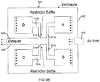
- FIG. 9A , FIG. 9B , and FIG. 9C show illustrative embodiments of fuel cell systems 900 with multiple fuel cell stacks in which baffles are used to control gas flow at the system level rather than in individual fuel cell manifolds.
- FIG. 9A shows an asymmetric multi-stack fuel cell system 900 that includes four fuel stacks A-D within a common enclosure 902 and in which all of the stacks share a single air source via an air intake assembly 910 and a single asymmetric exhaust assembly 904. As shown, the fuel cell stacks are labeled A, B, C, and D respectively. In a conventional asymmetric multi-stack fuel cell system, it would be expected that each stack would draw different amounts of air.
- the exhaust flow path from the C-D stack pair is shorter than the exhaust path from the A-B stack pair, and thus, in a conventional asymmetric multi-stack system, it would be expected that the C-D stack pair would draw more air flow than the A-B stack pair.
- the non-uniformity in the air flow to the stacks is corrected by strategically placing one or more baffles within the enclosure so as to increase resistance of the air flow to the stacks C and D.
- the baffles 906 are disposed in front of the oxidant inlet faces of the fuel cell stacks C and D so that the air has to travel around these baffles 906 before reaching the oxidant inlet faces of the stacks C and D.
- This construction creates a pressure balance that, in turn, causes the stacks C and D to draw the same amount of air flow as the stacks A and B.
- the baffles 906 may have a substantially planar or flat construction, or may be convex or concave with respect to the oxidant inlet faces of the stacks.
- the baffles 906 are formed from stainless steel sheets.
- baffles 906 are shown as solid, it is understood that the baffles 906 may include openings, perforations or vents therein so as to control the flow of air in a predetermined manner.
- the distance of each baffle 906 from the oxidant inlet face of the stack C, D may be varied so as to create a predetermined pressure balance and to provide more uniform air flow distribution among the stacks.
- the embodiment 9A uses one baffle 906 in front of each oxidant inlet face of the stack C, D, it is also contemplated within the scope of the invention that multiple baffles may be used to provide the desired air flow distribution.
- FIG. 9B shows another embodiment of the multi-stack fuel cell system 900, including stacks A, B, C and D housed within an enclosure 902 and supplied with air from a common air intake assembly 910 and having a common asymmetric exhaust assembly 904 for outputting the exhaust.
- the construction of the fuel cell system is substantially the same as the system shown in FIG. 9A , except for the way the baffles are employed.
- the stack flow balance is corrected using restrictor baffles 916 strategically placed in the exhaust assembly 904. As shown in FIG.
- the exhaust assembly 904 includes a common exhaust outlet 904a coupled to each fuel cell stack A-D by an exhaust output line 914a-914b, wherein the exhaust output line 914a couples the exhaust output of the fuel cell stack A to the common exhaust outlet 904a, the exhaust output line 914b couples the exhaust output of the stack B to the common exhaust outlet 904a, the exhaust output line 914c couples the exhaust output of the stack C to the common exhaust outlet 904a and the exhaust output line 914d couples the exhaust output of the stack to the common exhaust outlet 904a.
- the exhaust output lines 914c and 914d i.e. exhaust pipes
- the restrictor baffles 916 comprise simple blockages placed in the exhaust pipes to restrict the flow of exhaust coming from the stacks C and D and thereby cause the flow of air through the stacks C and D to be restricted.
- the restrictor baffles 916 are orifice plates placed into round exhaust pipes 914c, 914d.
- each of the restrictor baffles 916 may be replaced by a smaller pipe or a rougher pipe, or by a screen or matrix set in the pipe so as to increase the pressure drop through the exhaust of the stack C, D.
- restrictor baffles or other flow restriction devices may also be placed in the exhaust pipes of the stacks A or B, if stacks A and B also need to receive less gas flow.
- gas flow through the stacks A and/or B may be increased by increasing the size or diameter of the exhaust pipes 914a, 914b leading from stacks A and/or B to the common exhaust outlet 904a.
- the baffles 916 are formed from stainless steel material. However, it is understood that other materials may be used for the baffles. Moreover, although the baffles 916 are shown in FIG. 9B as solid and as extending partially through the width of the exhaust output line 914c, 914d, it is understood that the baffles 916 may include openings, perforations or vents therein and/or may extend through the entire width of the exhaust output pipe with one or more openings therein so as to control the exhaust flow in a predetermined manner. Also, in some embodiments, multiple baffles 916 may be used in each output line 914c, 914d so as to provide predetermined flow control. In addition, FIG.
- FIGB shows the baffles 916 being placed in the output lines 914c, 914d near the common exhaust outlet 904a, but it is understood that the positioning of the baffles 916 in the output lines 914c, 914d may be varied depending on the system requirements.
- FIG. 9C shows the multi stack fuel cell system 900 that has a similar construction as the systems of FIG. 9A and 9B , with the exception of the baffling used therein.
- the system 900 includes stacks A-D enclosed by the enclosure 902 and having a common asymmetric exhaust assembly 904 in which the exhaust output of each stack is connected to the common exhaust outlet 904a by a respective exhaust output line 914a-d.
- the stack flow balance is corrected using a baffle assembly 926 that uses the principle of the assembly shown in FIG. 8 , but with the flow traveling in the opposite direction to that of FIG. 8 .
- FIG. 926 shows the stack flow balance in FIG.
- the four fuel cell stacks, A, B, C, and D all empty into a common plenum 904a via the respective exhaust output lines 914a-d which have different path lengths.
- the exhaust path lengths of the respective output lines 914a-d from the stack pairs A-B and C-D can be changed using the baffle assembly 926 which includes an adjustable sleeve 926a configured to extend the path length of the respective output lines.
- the adjustable sleeve 926a is used to extend the path lengths of the output lines 914c and 914d by a predetermined amount.
- the adjustable sleeve 926a comprises a movable pipe member 927 which has a diameter and length that are smaller than the diameter and length of the exhaust outlet 904a and which can be fitted, movably within the exhaust outlet 904a.
- the adjustable sleeve 926a includes a baffle-like member 928 disposed between an outer surface of the pipe 927 and an inner surface of the exhaust outlet 904a. The member 928 is disposed near an end of the pipe 927 that is furthest from the stacks A and B.
- the positioning of the member 928 will depend on the configuration and requirements of the exhaust outlet 904a and of the output lines 914c, 914d.
- the adjustable sleeve 926a may be formed from stainless steel or from other suitable materials.
- the sleeve 926a can be moved within the exhaust outlet 904a, and the amount of extension by which the path lengths of the output lines 914c and 914d are extended is adjusted by moving the sleeve 926a either toward or away from the stacks A-B. For example, if the C-D pair are passing more flow than the A-B pair, then the adjustable sleeve 926 may be moved toward the stacks A-B so that an inlet 927a of the pipe 927 is further away from the stacks C-D.
- This exit plane adjustment results in lengthening of the exhaust path from the stacks C and D and in a pressure drop across the stacks C and D, thus, causing less flow through the stack pair C-D and increasing the flow through the stack pair A-B.
- Moving the adjustable sleeve 926 away from A-B so that the pipe inlet 927 is closer to the stacks C and D has the opposite effect of increasing the flow through the stack pair C-D and decreasing the flow through the stack pair A-B.
- the adjustable sleeve may be locked or welded into place, or the inlet 927a place may be marked and measured, and mass production could commence with interchangeable exhaust parts using that same measurement.
- the same flow control may be accomplished using an adjustable sleeve assembly with an upward-facing entrance instead of the inlet 927a, or with a fixed sleeve that has an adjustable opening or openings therein.
- FIG. 9A , FIG. 9B , and FIG 9C show illustrative examples of the how the single fuel cell stack manifold assemblies of FIGS. 1-8 may be adapted into baffle assemblies to control the gas flow through a multi-stack fuel cell system. It is understood that the specific configurations of the baffles and their positioning in the enclosure and/or the exhaust assembly of the multi-stack system may be varied to achieve various configurations and to control the flow of fuel and oxidant gases through the stacks.
Landscapes
- Life Sciences & Earth Sciences (AREA)
- Engineering & Computer Science (AREA)
- Manufacturing & Machinery (AREA)
- Sustainable Development (AREA)
- Sustainable Energy (AREA)
- Chemical & Material Sciences (AREA)
- Chemical Kinetics & Catalysis (AREA)
- Electrochemistry (AREA)
- General Chemical & Material Sciences (AREA)
- Fuel Cell (AREA)
Description
- This invention relates to fuel cell systems with at least one fuel cell stack and an external manifold and, in particular, to a manifold assembly or a flow distribution control assembly for use in a fuel cell system having at least one externally manifolded fuel cell stack. More particularly, the invention comprises an assembly that includes one or more baffle plates disposed in one or more of the manifolds of the fuel cell stack for controlling the flow distribution of the gases among multiple fuel cells of the stack. Variations of the baffling principal can be applied at a system level to regulate gas flow to a fuel system that includes two or more fuel cell stacks. More particularly, the system level baffling assembly comprises one or more baffle plates in an intake assembly and/or in an exhaust assembly of the multiple fuel cell system so that each fuel cell stack in the system receives a predetermined amount of gas flow.
- Relevant prior art is disclosed in the document
US 2005/129999 A1 . A fuel cell is a device that directly converts chemical energy in the form of a fuel into electrical energy by way of an electrochemical reaction. In general, like a battery, a fuel cell includes a negative electrode or anode and a positive electrode or cathode separated by an electrolyte that serves to conduct electrically charged ions between them. In contrast to a battery, however, a fuel cell will continue to produce electric power as long as fuel and oxidant are supplied to the anode and cathode, respectively. - In order to produce a useful amount of power, individual fuel cells are typically arranged in stacked relationship in series with an electrically conductive separator plate between each cell. A fuel cell stack may be categorized as an internally manifolded stack or an externally manifolded stack. In an internally manifolded stack, gas passages for delivering fuel and oxidant are built into the fuel cell plates themselves. In an externally manifolded stack, the fuel cell plates are left open on their ends and gas is delivered by way of manifolds or pans sealed to the respective faces of the fuel cell stack. The manifolds provide sealed passages for delivering fuel and oxidant gases to the fuel cells and preventing those gases from leaking either to the environment or to the other manifolds. In some fuel cell stack arrangements, the stack is placed in an enclosure and the enclosure environment represents one of the process gases. In such a system, at least three manifolds are required to provide inlet and outlet gas passages for the stack, each of which must be sealed to the stack. In any case, the manifolds must perform the above functions under the conditions required for operation of the fuel cell stack and for the duration of its life.
- An important aspect of the performance of an externally manifolded fuel cell stack is the flow distribution of process gases, i.e. fuel and oxidant process gases, among multiple fuel cells so that the process gases are evenly distributed to each of the fuel cells in the stack. In particular, it is desired that in a stack of fuel cells, all of the fuel cells in the stack get about the same amount of gas flow therethrough for the electrochemical reaction and for the purpose of cooling the cells uniformly or in predetermined regions. In conventional externally manifold fuel cell assemblies, fuel cells that are disposed closest to the anode exhaust pipe receive more fuel gas flow than fuel cells disposed further away from the exhaust pipe. As a result, the fuel cells with less gas flow therethrough are subjected to greater overheating while fuel cells with more gas flow produce more electrochemical reactions and thus, more power. This uneven gas distribution leads to a decreased fuel cell stack lifespan.
- Therefore, there is a need for an externally manifolded fuel cell stack for a greater control of the flow distribution of the gases to the fuel cells in the stack to more uniformly distribute the gas flow to all of the fuel cells in the stack. However, controlling of the fuel gas supply to individual fuel cells within the stack requires a complex piping and fuel delivery assembly. In addition, there is a need for controlling the distribution of fuel so as to provide cooling to the anode inlet area of the stack.
- It is, therefore, an object of the present invention to provide a manifold assembly that is capable of controlling the gas flow distribution through the fuel cells in the stack.
- It is a further object of the invention to provide a manifold assembly which has a simple construction and may be adjusted for a desired flow distribution profile.
- At a system level, the fuel cell system may include multiple fuel cell stacks that operate from a single fuel source provided by a fuel intake assembly and/or a single oxidant source provided by an oxidant gas intake assembly and/or exhaust spent gas into a single exhaust assembly. In such a multiple fuel cell stack system, each stack requires a predetermined amount of fuel and/or a predetermined percentage of the fuel in air. As flow control valves are costly and fragile in the hot, corrosive environments that surround the fuel cell stacks, it is desirable to have a flow control assembly that does not depend on such costly, fragile valves.
- It is, therefore, a further object of the invention to provide a baffling assembly that has a simple construction and is capable of controlling gas distribution to fuel cell stacks in a multiple fuel cell stack system.
- The present invention is defined by the appended claims. In accordance with the principles of the present invention, the above and other objectives are realized in a manifold assembly for use with a fuel cell stack, the manifold assembly comprising an external manifold for abutting and sealingly enclosing a face of the fuel cell stack, wherein the manifold comprises an enclosure for one of: providing inlet gas to the fuel cell stack and receiving exhaust gas from said fuel cell stack; and one or more baffles disposed in the enclosure of the external manifold. The one or more baffles one of: (a) controls gas flow distribution of the inlet gas from said enclosure to fuel cells of said fuel cell stack; and (b) controls direction of the exhaust gas flow within the enclosure.
- In certain embodiments, the external manifold is an anode exhaust manifold for receiving anode exhaust gas from an anode outlet face of said fuel cell stack, and the enclosure of the manifold includes an opening adapted to face the anode outlet face of the fuel cell stack and through which anode exhaust gas is output from the anode outlet face into the enclosure when the manifold abuts the anode outlet face. In such embodiments, there is at least one exhaust outlet formed in the enclosure for outputting the anode exhaust gas from the manifold, and at least one baffle is disposed in the enclosure between the exhaust outlet and the opening in the enclosure so as to control the direction of the anode exhaust gas flow received from fuel cells closest to the exhaust outlet around the baffle. In some embodiments, a height of the enclosure of the manifold is at least equal to or greater than a height of the fuel cell stack and the manifold assembly includes a plurality of baffles that are disposed in the enclosure along at least a portion of the enclosure's height. The baffles are disposed in the enclosure so as to control back pressure of the anode exhaust in predetermined fuel cells of the fuel cell stack and to reduce the amount of inlet fuel flow into the predetermined fuel cells. The predetermined fuel cells of the fuel cell stack include fuel cells that are closest to the exhaust outlet in the enclosure of the manifold and fuel cells that receive greater inlet fuel flow than other fuel cells in the fuel cell stack when the fuel cell stack is used with another manifold assembly without the baffles.
- In some embodiments, the enclosure of the manifold includes an outer wall opposing the opening, opposing top and bottom walls connected to the outer wall and first and second opposing sidewalls connected to the outer wall and to the top and bottom walls. Each of the baffles includes first and second opposing ends that are coupled with the first and second sidewalls of the enclosure, respectively, and the baffles are successively disposed along a portion of the height of the enclosure with successive baffles being separated by a vent. In some embodiments, each of the baffles is curved toward the outer wall of the enclosure so that the baffles are concave with respect to the anode outlet face of the fuel cell stack when the manifold assembly abuts the anode outlet face. One or more support members may be used to support the baffles in the enclosure, and the support member(s) may be coupled to one of the top or bottom walls or to one or both of the sidewalls. In some embodiments, one or more of the baffles may include a vent, a perforation and/or an opening therein at one or more predetermined locations.
- In certain embodiments, the external manifold is a cathode inlet manifold for enclosing a cathode inlet face of the fuel cell stack and for providing oxidant gas to the cathode inlet face. In such embodiments, at least one baffle controls gas flow distribution of the inlet oxidant gas from the enclosure to the fuel cells in the fuel cell stack so that portions of the fuel cells closest to an anode inlet face of the fuel cell stack receive increased flow of inlet oxidant gas when the manifold assembly abuts the cathode inlet face. Also, in such embodiments, the enclosure includes an outer wall, opposing top and bottom walls connected to the outer wall and opposing first and second sidewalls connected to the outer wall and to the top and bottom walls, with the first sidewall of the enclosure being disposed closest to an anode inlet face of the stack when the manifold assembly abuts the cathode inlet face of the stack. The at least one baffle in such embodiments extends along a portion of a width of the enclosure from the second sidewall of the enclosure in the direction of the first sidewall. The baffle may be substantially flat or may be curved, depending on the stack requirements.
- A fuel cell assembly with the manifold assemblies described above, and a method of controlling the flow distribution of gas are also described. Moreover, fuel cell systems with multiple fuel cell stacks housed in an enclosure and one or more baffles for controlling the gas flow at the system level are also described.
- The above and other features and aspects of the present invention will become more apparent upon reading the following detailed description in conjunction with the accompanying drawings, in which:
-
FIG. 1 is perspective view of an embodiment of an anode exhaust manifold assembly of the present invention; -
FIG. 2 is schematic view of another embodiment of the anode exhaust manifold assembly used with a fuel cell stack; -
FIGS. 3A-3C show side, top and front schematic views of the fuel cell stacks including the anode exhaust manifold assembly; -
FIGS. 4A and 4B show installation of baffles into the anode exhaust manifold to form the anode exhaust manifold assembly ofFIGS. 1 and 2 ; -
FIG. 5 shows a graph of flow distribution through the fuel cell stack using the anode exhaust manifold assembly ofFIGS. 2 and4A-4B and the conventional anode exhaust manifold assembly at different stack heights; -
FIG. 6A and 6B show side and top schematic views of an alternative embodiment of fuel cell stacks which include the anode exhaust manifold assembly and a cathode inlet manifold assembly. -
FIG. 7A shows a bar graph of cathode exhaust temperature distribution in the fuel cell stacks ofFIGS. 6A and 6B ; -
FIG. 7B shows a bar graph of cathode inlet temperature distribution in the fuel cell stacks ofFIGS. 6A and 6B ; -
FIG. 7C shows a bar graph comparing average cell temperatures at 50 percent and 75 percent stack height to the 0 percent stack height cell temperature for four fuel cell stacks without control baffle assemblies and a fifth stack that includes the flow control baffle assemblies ofFIGS. 6A and 6B ; -
FIG. 8 shows a schematic view of a fuel and/or oxidant inlet manifold that may be used in a fuel cell stack in addition to or instead of the anode exhaust manifold assembly ofFIGS. 1-4 ; and -
FIG. 9A ,FIG. 9B , andFIG. 9C show illustrative embodiments of fuel cell systems with multiple fuel cell stacks in which baffles are used to control gas flow at the system level. - The present invention provides a manifold assembly for use in a fuel cell system which controls gas flow distribution through a fuel cell stack of the system so as to achieve more uniform gas flow distribution through each fuel cell in the stack and to provide cooling to desired areas of the stack, such as the anode inlet area of the stack.
FIGS. 1-3C show illustrative embodiments of ananode manifold assembly 100 for use in the fuel cell system and for controlling the gas flow distribution through the fuel cell stack. Theanode manifold assembly 100 shown inFIGS. 1-3C is used with, or as part of, a fuel cell stack that comprises a plurality of stacked fuel cells and, in some cases, hundreds of stacked fuel cells. The fuel cell stack includes anode inlet and outlet faces for receiving and outputting, respectively, fuel gas and anode exhaust, and cathode inlet and outlet faces for receiving and outputting, respectively, oxidant gas and cathode exhaust. Each of the cathode inlet, anode inlet and anode outlet faces of the stack are typically enclosed by a manifold or a manifold assembly, so that oxidant gas and fuel gas are delivered through the respective manifolds abutting the cathode inlet and anode inlet faces, respectively, and anode exhaust is output into the manifold abutting the anode outlet face. Theanode manifold assembly 100 ofFIGS. 1-3C is adapted to sealingly abut the anode outlet face of the fuel cell stack and to receive anode exhaust gas output by the stack. - Typically, in fuel cell stacks that include many fuel cells, it is not economical to provide each fuel cell with an individual gas flow control assembly, such as a valve, for controlling the amount of gas supplied to the individual fuel cell. Therefore, the whole fuel cell stack is fed with the fuel and oxidant gases, respectively, as a unit, with the fuel being supplied to the whole stack from the anode inlet manifold and the oxidant being supplied to the whole stack from the cathode inlet manifold. Similarly, the anode outlet manifold, such as the
anode manifold assembly 100 ofFIGS. 1-3C , receives the anode exhaust from the entire stack, and thereafter outputs the received anode exhaust for processing or for venting to the outside through an exhaust outlet. It is important for the performance of the stack that each fuel cell in the stack receives about the same amount of fuel and oxidant gases. Since, as discussed above, those fuel cells closest to the exhaust outlet receive the most gas flow and the fuel cells furthest from the exhaust outlet receive less gas flow, a flow regulation device or assembly is needed for regulating the gas flow, particularly the fuel flow, so that each fuel cell receives the same amount of gas flow regardless of its distance from the exhaust outlet. The anode manifold assembly ofFIGS. 1-3C includes such a flow regulation assembly and is capable of adjusting the flow of fuel through the fuel cell stack so that the fuel flow is evenly distributed among the fuel cells in the stack. - As shown in
FIGS. 1-3C , theanode manifold assembly 100 includes an externalanode exhaust manifold 102 which, when used with the fuel cell stack, abuts the anode outlet face of the stack. Theanode exhaust manifold 102 includes anexhaust outlet 104 disposed at oneend 102a of the manifold 102, and one ormore baffles 106 disposed adjacent to, or near, theend 102a of themanifold 102. Theanode manifold 102 forms a compartment or an enclosure for enclosing the anode outlet face of the fuel cell stack and for receiving the anode exhaust gas from the fuel cell stack, and the enclosure has an opening through which the anode exhaust is received from the anode outlet face. An illustrative configuration of theanode manifold 102 is disclosed inU.S. Patent no. 6,877,611 , assigned to the same assignee herein. - In the present illustrative embodiment, the manifold 102 includes an
outer wall 102c which opposes the opening in the manifold, opposing top and bottom walls coupled to theouter wall 102c and opposing side walls coupled with the outer wall and the top and bottom walls. Outer ends of the top and bottom walls and of the sidewalls form anabutting surface 102d of the manifold that abuts the anode outlet face of the stack. Theexhaust outlet 104 in the embodiment shown inFIGS. 1-3C is formed in theouter wall 102c and is disposed near anend 102a of the manifold 102 which abuts the positive end or the negative end of the fuel cell stack. However, in other embodiments, theexhaust outlet 104 may be disposed in any other area of the manifold. - As shown, the one or
more baffles 106 are arranged in theanode exhaust manifold 102 within the space between theouter wall 102c of the manifold 102 and theabutting surface 102d of the manifold 102 which is adapted to abut the anode exhaust face of the fuel cell stack. The one ormore baffles 106 are disposed near theexhaust outlet 104 pipe in theouter wall 102c of themanifold 102. In particular, the one ormore baffles 106 are strategically disposed in or near the regions of the manifold where there is greater gas flow, which is typically near theexhaust outlet 104. In order to achieve more uniform distribution of inlet fuel to all of the fuel cells in the stack, the baffles are disposed in the enclosure of the manifold so as to control back pressure of the anode exhaust gas output from predetermined fuel cells of the fuel cell stack and to reduce the amount of inlet fuel flow into these predetermined fuel cells. The predetermined fuel cells of the stack include fuel cells that are closest to the exhaust outlet in the manifold and fuel cell receiving greater inlet fuel flow than other fuel cells in the stack when the stack is used with a conventional manifold that does not include baffles. - As shown in
FIGS. 1-3C , the one ormore baffles 106 extend along a portion of the height of themanifold 102. However, in some embodiments, depending on the configuration of the manifold 102 and the number of and location of theexhaust outlet 104, the one ormore baffles 106 may extend along the entire height of themanifold 102. - In certain embodiments, the
baffles 106 are formed from one or more stainless steel sheets. However, other materials which have similar thermal expansion coefficients to that of the manifold and which have sufficient strength at high temperature may be used for the baffles. - The embodiments of
FIGS. 1-3C includeseveral baffles 106 disposed successively in the enclosure of the manifold along at least a portion of the height of the manifold with vents orspaces 107 between adjacent orsuccessive baffles 106. Thevents 107 betweenadjacent baffles 106 are provided in the areas of the manifold where more flow is needed, so as to effectively control of the gas flow through the fuel cell stack. Although not shown inFIGS. 1-3C , the baffles may also include vents, perforations or openings in the baffles themselves, which are provided at predetermined locations where additional flow is needed, so as to further control the gas flow through the fuel cell stack. -
FIGS. 1 and 2 show the illustrative embodiments of the anode outlet manifold assembly which include three or fourbaffles 106 of varying sizes disposed in the manifold 102 near the exhaust pipe that forms theexhaust outlet 104. In the embodiment ofFIG. 1 , the anode outlet manifold assembly includes first, second andthird baffles 106a-c, while in the embodiment ofFIG. 2 , the anode outlet manifold assembly includes first, second, third andfourth baffles 106a-d, with the first, second andthird baffles 106a-c having the same or similar configuration as thebaffles 106a-c ofFIG. 1 . As shown inFIGS. 1 and 2 , each of thebaffles 106a-c or 106a-d is positioned in the manifold so that it extends across the width of the manifold 102, from one sidewall to the other sidewall. As shown, each baffle includes two opposing ends which are coupled to the opposing sidewalls of the manifold. In the illustrative embodiments shown, opposing ends of each baffle are connected to the respective sides of the manifold, within themanifold 102. Moreover, each of thebaffles 106a-d has at least a slight curvature thereto, curving toward the outer wall of the manifold, so that the baffles are concave with respect to the fuel cell stack face. In particular, for high temperature fuel cell operation, curved baffle structures are desired because they warp in a predictable manner during high-temperature operation, and do not interfere with other machine structures. However, in other embodiments, flat or convex baffles may be used. - As shown, a support structure or
rib 108 may be included for supporting the baffles within themanifold 102. As shown inFIG. 2 , thesupport structure 108 extends from theend 102a of the manifold along the central areas of thebaffles 106 and is connected to the manifold-side surfaces of thebaffles 106 so as to provide support for thebaffles 106. The attachment line of thesupport rib 108 is shown inFIG. 2 by a broken line 205c. The support rib may be coupled to one of the top and bottom walls of the manifold. Although the illustrative embodiments shown include only onesupport structure 108, in other embodiments, additional support structures may be used, or no support structure may be used, depending on the size of the baffles and the manifold requirements. Also, in some embodiments, the support rib may be attached to other areas of the manifold and/or may be attached to the fuel cell side surface of the baffles instead of the manifold-side surfaces. - As shown in
FIGS. 1 and 2 , thebaffles 106a-d are installed in the compartment or enclosure formed by the manifold between theouter wall 102a of the manifold and the stack-abuttingface 102d of the manifold. Thebaffles 106a-d are connected to the sidewalls of the manifold at a predetermined distance from the sidewall ends that form the stack-abuttingface 102d of the manifold. The predetermined distance is such that thebaffles 106a-d do not create excessive pressure at the anode outlet face of the stack and so that only a minor pressure penalty is incurred by the use of the baffles in themanifold 102. In the present illustrative embodiment, the predetermined distance from the sidewall ends abutting the anode outlet stack face to the point of connection of the baffles to the manifold sidewalls is 1 inch. However, in other embodiments, the predetermined distance may vary depending on the depth of the manifold and the size of the fuel cell stack. - In the illustrative embodiments shown in
FIGS. 1 and 2 , thefirst baffle 106a is disposed at or near theoutlet end 102a of the manifold and has a smaller height than the second and third 106b, 106c baffles. Thesecond baffle 106b is positioned adjacent thefirst baffle 106a with a slot or avent 107a formed therebetween, and thethird baffle 106c is positioned adjacent thesecond baffle 106b with a slot or avent 107b therebetween. The heights of the second andthird baffles first baffle 106a and of thefourth baffle 106d because thesecond baffle 106b is disposed directly opposite, or facing, theexhaust outlet 104 and thethird baffle 106c is disposed near theexhaust outlet 104, and correspond to the locations of the fuel cell stack which typically receive greater gas flow. Such positioning of the second andthird baffles - In
FIG. 2 , thefourth baffle 106d is disposed adjacent thethird baffle 106c with a vent or aslot 107c therebetween. The height of thefourth baffle 106d in this illustrative embodiment is smaller than the heights of the second and third baffles and is similar to the height of thefirst baffle 106a. Although the embodiment shown inFIG. 1 does not include thefourth baffle 106d, it is understood that the configuration of the anode outlet manifold assembly ofFIG. 1 may be varied so as to include thefourth baffle 106d following thethird baffle 106c, similar to the embodiment shown inFIG. 2 . -
FIGS. 4A and 4B show photographs of thebaffles 106a-d installed in the enclosure of themanifold 102 of the anode manifold assembly ofFIG. 2 . The installation of thebaffles 106a-d in the anode manifold assembly ofFIG. 1 is similar, with thefourth baffle 106d being omitted from the anode manifold assembly ofFIG. 1 . As shown inFIGS. 4A and 4B , thefirst baffle 106a is installed adjacent to theoutlet end 102a of the manifold and extends beyond a fixed end plate of the fuel cell stack which the manifold 102 would abut. In the present illustrative embodiment, there is a ¼ or a ½ inch gap between theoutlet end 102a of the manifold and thefirst baffle 106a, and the first baffle is positioned at 4.5 inches outside of the fixed end plate. The height of the first baffle is about 7 inches. Thesecond baffle 106b is installed at a position adjacent or successive to thefirst baffle 106a along the height of the stack, about 4 inches from the fixed end plate of the stack that the manifold 102 would abut. As shown, there is a slot or avent 107a between thefirst baffle 106a and thesecond baffle 106b, which has a height of about 1/4 inches. The height of thesecond baffle 106b is about 23.5 inches. - As shown in
FIG. 4A , thethird baffle 106c is installed at a position adjacent or successive to the second baffle along the height of the stack and about 28 inches from the fixed end plate of the stack that the manifold 102 would abut. There is a slot or avent 107b formed between thesecond baffle 106b and thethird baffle 106c, which has a height of about 1/4 inches. The height of the third baffle is about 24.5 inches. Finally, thefourth baffle 106d is installed at a position adjacent or successive to the third baffle along the height of the stack that is about 52 inches from the fixed end plate of the stack that the manifold would abut, and extends to a position that is about 59 inches from the fixed end plate of the stack. The height of thefourth baffle 106d is about 7 inches. There is also provided a vent or aslot 107c between the third andfourth baffles fourth baffle 106d, the space in the manifold is open to itsouter wall 102c without further baffles, and exhaust is free to flow within the manifold to an area between thebaffles 106 and the manifoldouter wall 102c toward theexhaust outlet 104. The baffle arrangement shown inFIGS. 4A and 4B is suitable for anode manifold assemblies used with 300kW fuel cell stack systems, such asDFC® 300 manufactured by FuelCell Energy, Inc. However, it is understood that the number of the baffles used in the anode manifold assembly and their arrangement may be varied depending on the dimensions and requirements of the manifold and of the fuel cell system. - Referring now to
FIG. 2 , the flow of the fuel through thefuel cell system 200 with themanifold assembly 100 is shown using arrows. As shown inFIG. 2 , thefuel cell system 200 includes a fuel cell stack 202 that has ananode inlet face 202a adapted to receive fuel gas, ananode outlet face 202b which opposes theanode inlet face 202a and which is adapted to output anode exhaust, acathode inlet face 202c adapted to receive oxidant gas and acathode outlet face 202d adapted to output cathode exhaust. The fuel cell stack 202 is schematically shown as a porous block, which is formed by the plurality of stacked fuel cells. Theanode manifold assembly 100 abuts theanode outlet face 202b of the fuel cell stack 202 and has a similar construction to the manifold assembly ofFIGS. 4A and 4B , and similar to the manifold assembly ofFIG. 1 , with the exception of the addedfourth baffle 106d. Although not shown inFIG. 2 , the fuel cell stack 202 may also include an anode inlet manifold abutting theanode inlet face 202a, a cathode inlet manifold abutting thecathode inlet face 202c and in some embodiments a cathode outlet manifold abutting thecathode outlet face 202d. - The flow of fuel into the fuel cell stack 202 is shown in
FIG. 2 by thearrows 205a labeled as "flow in". In particular, the fuel cell stack 202 receives fuel through theanode inlet face 202a, which is typically delivered via the anode inlet manifold. After the fuel is used in the fuel cell stack, the fuel cells of the stack output anode exhaust, comprising spent fuel gas, through theanode outlet face 202b into the anode manifold assembly 101. The flow of anode exhaust from theanode outlet face 202b of the stack is shown usingsmaller arrows 205b inFIG. 2 . - The flow of
anode exhaust 205b leaving the fuel cells in the area of, or in proximity of, theexhaust outlet 104 is redirected by thebaffles 106 of theanode manifold assembly 100 so that the anode exhaust flows around the baffles and/or through thevents 107 between the baffles. That is, the anode exhaust flow from the stack to theexhaust outlet 104 is caused by thebaffles 106 to travel over and then under the baffle plates and/or to pass through the strategically placed vents between adjacent or successive baffles. In this way, thebaffles 106 restrict the flow of the anode exhaust in the area of theexhaust outlet 104, and reduce the pressure drop across the fuel cells located in the area of, or proximity with, theexhaust outlet 104. As a result, the pressure drop across the fuel cells in the area of theexhaust outlet 104 is more uniform with the pressure drop across the fuel cells disposed farther away from the exhaust outlet, thereby creating a more uniform distribution of fuel flow through the fuel cells in the stack, independent of how closely or far away the fuel cells are located relative to the exhaust outlet in the manifold. - As mentioned above, in some embodiments, the
baffles 106 may also have vents, perforations and/or other openings formed in the baffles themselves (not shown) and strategically placed so as to control the flow and direction of the anode exhaust to the exhaust outlet. In such embodiments, the anode exhaust flow from the stack to the exhaust outlet in the area of the exhaust outlet would also travel through such vents, perforations or openings in the baffles. The vents, perforations and/or openings in the baffles provide for additional control of fuel flow and fuel flow distribution through the fuel cell stack. -
FIGS. 3A, 3B and 3C schematically show side, front and top views of theanode manifold assembly 100 abutting thefuel cell stack 200, shown as a porous block. As shown inFIGS. 3A-3C , thefuel cell stack 200 also includes aninlet manifold 208 through which fuel is supplied to thefuel cell stack 200. The flow of fuel is shown inFIGS. 3A and 3C using arrows 205a. As shown inFIGS. 3A and 3B , theanode manifold assembly 100 includes a plurality of baffles, i.e. four or five baffles, which are disposed in the area of theexhaust outlet 104 so as to restrict the flow of anode exhaust leaving the fuel cell stack in the area of theexhaust outlet 104, and as a result, control the flow of fuel into the fuel cells of the stack so that the fuel is more uniformly distributed among the fuel cells of the stack. -
FIG. 5 shows a graph of gas flow distribution in fuel cell stacks with conventional anode exhaust manifolds and in fuel cell stacks with the manifold assembly of the present invention, such as the manifold assemblies shown inFIGS. 2 and4A-4B . InFIG. 5 , the X-axis represents stack height percentage, or the position of the fuel cells along the height of the fuel cell stack, while the Y-axis represents the measured flow of fuel through the fuel cells. A plot of the fuel flow distribution through the fuel cell stack with a conventional manifold assembly, without any baffles, is labeled as "No Baffle," while plots of the fuel flow distributions through fuel cell stacks that included the anode manifold assembly of the present invention are labeled as "With Baffle." - As can be seen, the flow distribution in the conventional fuel cell stacks with conventional manifolds varies from one end of the stack to the other end of the stack, so that the fuel flow is greatest in the area of 0-10% of the stack height, corresponding to the area closest to the anode exhaust outlet, and lowest in the area of 80-100% of the stack height, corresponding to the area furthest away from the anode exhaust outlet. In contrast, the flow distribution of the fuel in the fuel cell stacks that used the anode manifold assembly of the present invention abutting the anode outlet face of the stack was substantially uniform throughout the stack, and varied only slightly from one area to another. It is further noted that the slight variations in the fuel flow distribution may be corrected by using strategically placed vents in the area of 20-30% of the stack height and/or strategically placed additional baffles in the area of 55-75% of the stack height.
- In some embodiments, baffles may be employed in other manifold assemblies so as to further control the flow of gases through the fuel cell stack and to control the temperature in the stack. In particular, one or more baffles may be used in a cathode inlet manifold assembly, which is adapted to abut the cathode inlet face of the stack, in order to control the flow of oxidant gas into the fuel cell stack and to control the temperature in the fuel cell stack.
- As shown in
FIG. 2 , thecathode inlet face 202c of the stack is substantially perpendicular to theanode inlet face 202a of the stack, and a portion of the cathode inlet face 202c1 extends along theanode inlet 202a while a portion of the cathode inlet face 202c2 extends along theanode outlet face 202b. During fuel cell operation, cooling is needed in the anode inlet region of the stack and uniform cathode exhaust temperatures along the height of the stack are desired. Such temperature characteristics may be achieved by controlling the flow of oxidant gas to the fuel cell stack so as to provide greater oxidant flow to the area of the cathode inlet 202c1 that is near the anode inlet portion of the stack. This oxidant gas flow control may be achieved by providing one or more baffles in the cathode inlet manifold, and in particular, by positioning the one or more baffles in the cathode inlet manifold so that the area of the cathode inlet face that is adjacent or near the anode inlet of the stack receives greater oxidant flow. In the illustrative embodiments shown, the one or more baffles are positioned in the cathode inlet manifold in the area of the cathode inlet 202c2 that is near the anode outlet so as to provide an opening in the area of the cathode inlet 202c1 near the anode inlet. -
FIGS. 6A and 6B schematically show the side and top views of thefuel cell stack 200 that includes both theanode manifold assembly 100 ofFIGS. 1-4A and a cathodeinlet manifold assembly 300 abutting thecathode inlet face 202c of the stack. The construction of theanode manifold assembly 100 in this embodiment is the same as in the above-described embodiments, and thus, a description of theanode manifold assembly 100 is omitted. As shown inFIGS. 6A and 6B , the cathodeinlet manifold assembly 300 includes acathode inlet manifold 302 abutting and enclosing thecathode inlet face 202c of thestack 200. Thecathode inlet manifold 302 forms an enclosure or a compartment for receiving oxidant gas and supplies the oxidant gas to fuel cell cathodes of the fuel cell stack. The manifold 302 may have a construction as described inU.S. Pat. No. 6,887,611 , assigned to the same assignee herein. In particular, the manifold 302 includes an outer wall, opposing top and bottom walls connected to the outer wall and opposing sidewalls 302a, 302b connected to the outer wall and to the top and bottom walls. - As shown in
FIGS. 6A and 6B , the cathodeinlet manifold assembly 300 includes anoxidant inlet 304 and one ormore baffles 306 for controlling the flow of oxidant gas from theoxidant inlet 304 through the enclosure of the manifold 302 and to the fuel cell stack. In the embodiment shown, the cathodeinlet manifold assembly 300 includes onebaffle 306 which extends from afirst sidewall 302a of the manifold 302, which extends along the fuel outlet side of the stack, and toward the opposingsecond sidewall 302b of the manifold 302, which extends along the fuel inlet side of the stack. Thebaffle 306 extends only part of the way from thefirst side 302a to thesecond side 302b, so as to create anopening 307 along thesecond side 302b of the manifold enclosure. Thebaffle 306 may be supported using one ormore support members 308 which, inFIG. 6A , connect an end of thebaffle 306 to thesecond sidewall 302b of the manifold so as to provide support to thebaffle 306. - During operation, oxidant gas supplied to the
cathode inlet manifold 302 through theinlet 304 is directed by thebaffle 306 to travel along and around the baffle before reaching thefuel cell stack 200. Since theopening 307 extends along the second sidewall of the manifold 302b which is adjacent the fuel inlet side of the stack, more oxidant gas flow is provided to areas of the fuel cells at or near theopening 307. In this way, additional cooling is provided to the fuel inlet area of the fuel cell stack through heat exchange between the oxidant flow through the cathodes near the fuel inlet area of the stack and fuel flow through the inlet area of the anodes. Although not shown inFIGS. 6A and 6B , other openings or perforations in the baffle may be provided and disposed strategically so as to provide further cooling to other areas of the stack, as needed. Moreover, although the embodiment shown inFIGS. 6A and 6B only includes onebaffle 306, multiple baffles may be used so as to provide desired oxidant flow control. - The effects of the
baffles anode manifold assembly 100 and of the cathodeinlet manifold assembly 300, respectively, is shown inFIGS. 7A, 7B , and7C . In particular,FIGS. 7A and 7B show cathode exhaust and cathode inlet temperature distributions from negative to positive ends of the fuel cell stack which uses the cathodeinlet manifold assembly 300 ofFIGS. 6A and 6B abutting its cathode inlet face and theanode manifold assembly 100 ofFIGS. 2 and4A-4B abutting its anode outlet face. between InFIGS. 7A and 7B , the X-axis represents the percent power level at which the fuel cell stack operates and the Y-axis represents the measured temperature in degrees F. InFIGS. 7A and 7B , each group of bars, i.e. groups of four bars inFIG. 7A and groups of five bars inFIG. 7B , represents different positions within the stack, extending from a negative end of the stack, i.e. left-most bar in each group, to a positive end of the stack, i.e. right-most bar in each group. -
FIG. 7C shows a comparison between four conventional stacks, i.e. stacks A, B, C, and D, that do not include any baffles in their manifolds, and a fifth stack, i.e. stack E, that has both theanode manifold assembly 100 ofFIGS. 2 and4A-4B and the cathodeinlet manifold assembly 300 ofFIGS. 6A and 6B . InFIG. 7C , the X-axis represents the five different stacks, listed as A, B, C, D, and E, and the Y-axis represents the fuel cell cathode exhaust temperature difference from the lowest or zero percent height fuel cell in the fuel cell stacks. The 0% height fuel cell corresponds to the fuel cell at the negative end of the fuel cell stack. InFIG. 7C , each stack A-E includes a measurement of the cathode exhaust temperature difference between the 50% stack height position and the 0% stack height position and a measurement of the cathode exhaust temperature difference between the 75% stack height position and the 0% stack height position. - As shown in
FIG. 7A , the temperature of the cathode exhaust output from the fuel cell stacks tested had a variation of about 10 degrees F from the negative end of the stack to the positive end of the stack at different current densities. This temperature distribution is the opposite of the temperature distribution typically seen in fuel cells that use conventional manifolds without any baffles. In addition, as shown inFIG. 7A , the highest temperature of the cathode exhaust was typically output from the middle of the fuel cell stack, as shown by the bar labeled 376C. - As shown in
FIG. 7B , the temperature of the oxidant gas in the cathode inlet areas of the fuel cell stack tested had a variation of about 12 degrees F from the negative end to the positive end, which is within typical range of variation seen in fuel cell stacks with control baffles present in the manifolds. In addition, a lower cathode inlet temperature was observed near the negative end of the fuel cell stack. - As shown in
FIG. 7C , in the fuel cell stacks without control baffles in their manifolds, i.e. stacks A, B, C, and D, the cathode exhaust temperature typically decreases with respect to the cathode exhaust temperature of the lowest fuel cell or 0% height cell in the stack. As shown, in stacks A, B, C and D, the cathode exhaust temperature at the 50% stack height is typically 8°F to 13°F lower than at the 0% height of the stack, and can be more than 15°F lower than at the 0% height of the stack in an extreme case of the stack B. In stacks A, B, C and D, the cathode exhaust temperature at the 75% stack height is typically 13°F to 18°F lower than at the 0% stack height, and can be more than 25°F lower than at the 0% stack height in an extreme case of the stack B.FIG. 7C also shows the temperature difference measured for stack E, which has both cathode inlet manifold assembly with control baffles and anode manifold assembly with the anode exhaust control baffles. The result for stack E shows that the temperature of the cathode exhaust from fuel cells at the 50% and 75% stack height are 5°F to 6°F higher than the cathode exhaust temperature at the 0% stack height. In further arrangements of the baffles in the anode manifold assemblies and the cathode exhaust manifold assemblies, the cathode exhaust temperature difference between a fuel cell at any height in the stack and the negative end fuel cell at the 0% height of the stack can be brought to 4°F or less. - The observations shown in
FIGS. 7A, 7B and7C and particularly, the observations with respect to the cathode exhaust temperatures, show that thebaffles baffles 106a-d of the anode manifold assembly, can produce increased uniformity in the temperatures within the stack. For example, in some embodiments,shorter baffles 106a-d, which have a combined height of 55 inches instead of 60 inches, would reduce the fuel flow to the free, unbaffled, end of the stack and are expected to improve the cathode exhaust temperature uniformity. In addition to providing more uniform temperatures in the stack, thebaffle 306 of the cathode inlet manifold assembly also reduces the anode inlet area temperature. -
FIG. 8 schematically shows an alternative embodiment of aninlet manifold assembly 400, which may be used either as the cathodeinlet manifold assembly 300 abutting the cathode inlet face of the stack or as an anode inlet manifold assembly abutting the anode inlet face of the stack. Theinlet manifold assembly 400 includes aninlet manifold 402, which has a similar construction to conventional anode and cathode inlet manifolds and which is adapted to sealingly enclose an inlet face of the fuel cell stack. Theinlet manifold 402 forms an enclosure or compartment for receiving inlet gas via aninlet pipe 404 that supplies the inlet gas to theinlet manifold 402. As shown inFIG. 8 , theinlet pipe 404 extends into the manifold 402 and along at least a portion of the height of themanifold 402. The manifold 402 also includes one ormore baffles 406 disposed within the enclosure of the manifold along the height of the manifold and forming a plurality of openings oroutlets 407 between thebaffles 406 for outputting the inlet gas from the enclosure of the manifold to the stack face. For high temperature applications, thebaffles 406 may be formed from stainless steel. - In some embodiments, a barrier-type member may be installed within the enclosure instead of the baffles, with the barrier-type member covering all or a portion of the enclosure area and the barrier-type member including a plurality of outlets or openings formed therein. In this embodiment, the inlet gas received in the enclosure of the manifold is blocked by the barrier-type member from directly flowing to the fuel cell stack which the manifold abuts and instead is directed through the outlets or
openings 407 formed in the barrier-type member to the stack face so as to provide a desired distribution. Like the baffles, the barrier-type member may be formed from a stainless steel sheet. - The positioning and number of the
baffles 406 of the barrier-type member within the manifold enclosure will depend on the desired flow distribution and on whether the gas directed by the manifold is a fuel inlet gas or an oxidant inlet gas. For example, in some embodiments, the baffles or the barrier type member will extend along the entire width of the stack from one sidewall to another, while in other embodiments, the baffles or the barrier-type member will extend only along a portion of the stack width. Also, in the embodiment shown, the baffles or the barrier-type member is disposed along the entire height of the stack. However, in other embodiments, the baffles or the barrier-type member may be disposed only along a portion of the stack height. - In the embodiment shown in
FIG. 8 , the outlets oropenings 407 formed between thebaffles 406 or in the barrier-type member disposed in the manifold enclosure are provided at substantially uniform intervals so as to provide a more uniform distribution of the inlet gas to the stack face. However, in other embodiments, the outlets or openings . 407 may be formed at varying intervals and in varying locations of the enclosure so as to provide customized flow distribution to the fuel cell stack. In this way, the flow distribution of the inlet gas to the stack may be adjusted so as to control the temperature within the stack, to more uniformly distribute the gas among the fuel cells in the stack, and to control the thermodynamic profile of the stack. -
FIG. 9A ,FIG. 9B , andFIG. 9C show illustrative embodiments offuel cell systems 900 with multiple fuel cell stacks in which baffles are used to control gas flow at the system level rather than in individual fuel cell manifolds.FIG. 9A shows an asymmetric multi-stackfuel cell system 900 that includes four fuel stacks A-D within acommon enclosure 902 and in which all of the stacks share a single air source via anair intake assembly 910 and a singleasymmetric exhaust assembly 904. As shown, the fuel cell stacks are labeled A, B, C, and D respectively. In a conventional asymmetric multi-stack fuel cell system, it would be expected that each stack would draw different amounts of air. In particular, the exhaust flow path from the C-D stack pair is shorter than the exhaust path from the A-B stack pair, and thus, in a conventional asymmetric multi-stack system, it would be expected that the C-D stack pair would draw more air flow than the A-B stack pair. In the system ofFIG. 9A , the non-uniformity in the air flow to the stacks is corrected by strategically placing one or more baffles within the enclosure so as to increase resistance of the air flow to the stacks C and D. In the illustrative embodiment ofFIG. 9A , thebaffles 906 are disposed in front of the oxidant inlet faces of the fuel cell stacks C and D so that the air has to travel around thesebaffles 906 before reaching the oxidant inlet faces of the stacks C and D. This construction creates a pressure balance that, in turn, causes the stacks C and D to draw the same amount of air flow as the stacks A and B. Thebaffles 906 may have a substantially planar or flat construction, or may be convex or concave with respect to the oxidant inlet faces of the stacks. In the illustrative embodiment ofFIG. 9A , thebaffles 906 are formed from stainless steel sheets. Although thebaffles 906 are shown as solid, it is understood that thebaffles 906 may include openings, perforations or vents therein so as to control the flow of air in a predetermined manner. In addition, the distance of eachbaffle 906 from the oxidant inlet face of the stack C, D may be varied so as to create a predetermined pressure balance and to provide more uniform air flow distribution among the stacks. Moreover, although the embodiment 9A uses onebaffle 906 in front of each oxidant inlet face of the stack C, D, it is also contemplated within the scope of the invention that multiple baffles may be used to provide the desired air flow distribution. -
FIG. 9B shows another embodiment of the multi-stackfuel cell system 900, including stacks A, B, C and D housed within anenclosure 902 and supplied with air from a commonair intake assembly 910 and having a commonasymmetric exhaust assembly 904 for outputting the exhaust. The construction of the fuel cell system is substantially the same as the system shown inFIG. 9A , except for the way the baffles are employed. InFIG. 9B , instead of using the air intake baffles 906 used inFIG. 9A , the stack flow balance is corrected using restrictor baffles 916 strategically placed in theexhaust assembly 904. As shown inFIG. 9B , theexhaust assembly 904 includes acommon exhaust outlet 904a coupled to each fuel cell stack A-D by anexhaust output line 914a-914b, wherein theexhaust output line 914a couples the exhaust output of the fuel cell stack A to thecommon exhaust outlet 904a, theexhaust output line 914b couples the exhaust output of the stack B to thecommon exhaust outlet 904a, theexhaust output line 914c couples the exhaust output of the stack C to thecommon exhaust outlet 904a and theexhaust output line 914d couples the exhaust output of the stack to thecommon exhaust outlet 904a. - As shown in
FIG. 9B , theexhaust output lines restrictor baffles 916 disposed therein. The restrictor baffles 916 comprise simple blockages placed in the exhaust pipes to restrict the flow of exhaust coming from the stacks C and D and thereby cause the flow of air through the stacks C and D to be restricted. In some embodiments, the restrictor baffles 916 are orifice plates placed intoround exhaust pipes FIG. 9B , restrictor baffles or other flow restriction devices may also be placed in the exhaust pipes of the stacks A or B, if stacks A and B also need to receive less gas flow. In other embodiments, gas flow through the stacks A and/or B may be increased by increasing the size or diameter of theexhaust pipes common exhaust outlet 904a. - In the illustrative embodiment of
FIG. 9B , thebaffles 916 are formed from stainless steel material. However, it is understood that other materials may be used for the baffles. Moreover, although thebaffles 916 are shown inFIG. 9B as solid and as extending partially through the width of theexhaust output line baffles 916 may include openings, perforations or vents therein and/or may extend through the entire width of the exhaust output pipe with one or more openings therein so as to control the exhaust flow in a predetermined manner. Also, in some embodiments,multiple baffles 916 may be used in eachoutput line FIG. 9B shows thebaffles 916 being placed in theoutput lines common exhaust outlet 904a, but it is understood that the positioning of thebaffles 916 in theoutput lines -
FIG. 9C shows the multi stackfuel cell system 900 that has a similar construction as the systems ofFIG. 9A and9B , with the exception of the baffling used therein. As shown, thesystem 900 includes stacks A-D enclosed by theenclosure 902 and having a commonasymmetric exhaust assembly 904 in which the exhaust output of each stack is connected to thecommon exhaust outlet 904a by a respectiveexhaust output line 914a-d. As shown inFIG. 9C , the stack flow balance is corrected using abaffle assembly 926 that uses the principle of the assembly shown inFIG. 8 , but with the flow traveling in the opposite direction to that ofFIG. 8 . As shown inFIG. 9C , the four fuel cell stacks, A, B, C, and D, all empty into acommon plenum 904a via the respectiveexhaust output lines 914a-d which have different path lengths. However, the exhaust path lengths of therespective output lines 914a-d from the stack pairs A-B and C-D can be changed using thebaffle assembly 926 which includes anadjustable sleeve 926a configured to extend the path length of the respective output lines. - In
FIG. 9C , theadjustable sleeve 926a is used to extend the path lengths of theoutput lines FIG. 9C , theadjustable sleeve 926a comprises amovable pipe member 927 which has a diameter and length that are smaller than the diameter and length of theexhaust outlet 904a and which can be fitted, movably within theexhaust outlet 904a. In addition, theadjustable sleeve 926a includes a baffle-like member 928 disposed between an outer surface of thepipe 927 and an inner surface of theexhaust outlet 904a. Themember 928 is disposed near an end of thepipe 927 that is furthest from the stacks A and B. However, the positioning of themember 928 will depend on the configuration and requirements of theexhaust outlet 904a and of theoutput lines adjustable sleeve 926a may be formed from stainless steel or from other suitable materials. - The
sleeve 926a can be moved within theexhaust outlet 904a, and the amount of extension by which the path lengths of theoutput lines sleeve 926a either toward or away from the stacks A-B. For example, if the C-D pair are passing more flow than the A-B pair, then theadjustable sleeve 926 may be moved toward the stacks A-B so that aninlet 927a of thepipe 927 is further away from the stacks C-D. This exit plane adjustment results in lengthening of the exhaust path from the stacks C and D and in a pressure drop across the stacks C and D, thus, causing less flow through the stack pair C-D and increasing the flow through the stack pair A-B. Moving theadjustable sleeve 926 away from A-B so that thepipe inlet 927 is closer to the stacks C and D has the opposite effect of increasing the flow through the stack pair C-D and decreasing the flow through the stack pair A-B. After a predetermined flow balance is achieved, the adjustable sleeve may be locked or welded into place, or theinlet 927a place may be marked and measured, and mass production could commence with interchangeable exhaust parts using that same measurement. The same flow control may be accomplished using an adjustable sleeve assembly with an upward-facing entrance instead of theinlet 927a, or with a fixed sleeve that has an adjustable opening or openings therein. Once the desired flow balance is established in a prototype, the position of the sleeve entrance or other openings could be fixed in subsequently manufactured exhaust assemblies. -
FIG. 9A ,FIG. 9B , andFIG 9C show illustrative examples of the how the single fuel cell stack manifold assemblies ofFIGS. 1-8 may be adapted into baffle assemblies to control the gas flow through a multi-stack fuel cell system. It is understood that the specific configurations of the baffles and their positioning in the enclosure and/or the exhaust assembly of the multi-stack system may be varied to achieve various configurations and to control the flow of fuel and oxidant gases through the stacks. - In all cases it is understood that the above-described arrangements are merely illustrative of the many possible specific embodiments, which represent applications of the present invention. Numerous and varied other arrangements, including use of different materials and various configurations of components of the manifold assembly, can be readily devised in accordance with the principles of the present invention without departing from the scope of the invention as claimed in the appended claims.
Claims (12)
- A manifold assembly for use with a fuel cell stack (200, 202), said manifold assembly comprising:an external anode exhaust manifold (102) for abutting and sealingly enclosing an anode outlet face (202b) of the fuel cell stack (200, 202), wherein the manifold comprises:an enclosure for receiving anode exhaust gas from the fuel cell stack (200, 202), the enclosure including:an opening adapted to face the anode outlet face (202b) of the fuel cell stack (200, 202) and through which the anode exhaust gas is output from the anode outlet face (202b) into the enclosure when the manifold abuts the anode outlet face (202b),an outer wall (102c) opposing the opening,opposing top and bottom walls connected to the outer wall (102c),opposing first and second side walls connected to the outer wall (102c) and to the top and bottom walls, andan exhaust outlet (104) formed in the outer wall (102c) for outputting the anode exhaust gas from the manifold, anda plurality of baffles (106, 306) disposed in said enclosure, said baffles (106, 306) being configured to control a direction of a flow of the anode exhaust gas flow within the enclosure,wherein each of the plurality of baffles (106, 306) includes first and second opposing ends coupled with the first and second sidewalls of the enclosure, respectively,wherein said baffles (106, 306) are successively disposed along a portion of the height of the enclosure with successive baffles (106, 306) being separated by a vent (107, 107a,107b,107c) or a space, andwherein at least one of the baffles (106, 306) is disposed in the enclosure between the exhaust outlet (104) and the opening of the enclosure so as to control the direction of the flow of the anode exhaust gas received from fuel cells closest to the exhaust outlet (104) to flow around said at least one of said baffles (106, 306).
- The manifold assembly in accordance with claim 1, wherein said baffles (106, 306) are disposed in the enclosure so as to control back pressure of said anode exhaust in predetermined fuel cells of said fuel cell stack (200, 202) and to reduce the amount of inlet fuel flow into said predetermined fuel cells.
- The manifold assembly in accordance with claim 2, wherein the predetermined fuel cells of the fuel cell stack (200, 202) include fuel cells closest to the exhaust outlet (104) in the enclosure of the manifold and fuel cells receiving greater inlet fuel flow than other fuel cells in the fuel cell stack (200, 202) when the fuel cell stack (200, 202) is used with another manifold assembly without said one or more baffles (106, 306).
- The manifold assembly in accordance with claim 1, wherein each of said baffles (106, 306) is curved toward the outer wall (102c) of the enclosure so that said baffles (106, 306) are concave with respect to the anode outlet face (202b) of the fuel cell stack (200, 202) when the manifold assembly abuts the anode outlet face (202b).
- The manifold assembly in accordance with claim 1, wherein one or more of said baffles (106, 306) includes one or more of a vent (107, 107a,107b,107c), a perforation and an opening therein at one or more predetermined locations.
- The manifold assembly in accordance with claim 1, further comprising one or more support members (308) configured to support said baffles (106, 306) in the enclosure, at least one of the support members (308) being coupled to one of the top and bottom walls of the enclosure and extending along at least a portion of the height of the enclosure.
- A fuel cell stack (200, 202) assembly comprising:a fuel cell stack (200, 202) including an anode inlet face (202a), an anode outlet face (202b) opposing the fuel
inlet face, a cathode inlet face (202c) and a cathode outlet face (202d) opposing the cathode inlet face (202c); andat least one manifold assembly in accordance with any of claims 1 to 6. - A method of controlling gas flow distribution in a fuel cell stack (200, 202), said method comprising:providing a fuel cell stack (200, 202) including an anode inlet face (202a), an anode outlet face (202b), a
cathode inlet face (202c) and a cathode outlet face (202d); andattaching to the fuel cell stack (200, 202) at least one manifold assembly in accordance with any of claims 1 to 6. - A manifold assembly for use with a fuel cell stack (200, 202), said manifold assembly comprising:an external cathode inlet manifold (302) for abutting and sealingly enclosing a cathode inlet face (202c) of the fuel cell stack (200, 202), wherein the manifold comprises:an enclosure for providing oxidant gas to said fuel cell stack (200, 202), the enclosure including:an opening adapted to face the cathode inlet face (202c) of the fuel cell stack (200, 202) and through which the oxidant gas is input to the cathode inlet face (202c) from the enclosure when the manifold abuts the cathode inlet face (202c),an outer wall (102c) opposing the opening,opposing top and bottom walls connected to the outer wall (102c),opposing first and second side walls connected to the outer wall (102c) and to the top and bottom walls, wherein the first sidewall is disposed closest to an anode inlet face (202a) of the stack when the manifold assembly abuts the cathode inlet face (202c) of the stack, andan oxidant inlet formed in the outer wall (102c) for inputting the oxidant gas to the manifold, andat least one baffle disposed in said enclosure, said at least one baffle being configured to control a direction of a flow of the oxidant gas flow within the enclosure,wherein the at least one baffle extends along a portion of a width of the enclosure from the second sidewall of the enclosure in a direction of the first side wall, such that the at least one baffle controls gas flow distribution of the inlet oxidant gas from the enclosure to the fuel cells in the fuel cell stack (200, 202) so that portions of the fuel cells closest to an anode inlet face (202a) of the fuel cell stack (200, 202) receive increased flow of oxidant gas when the manifold assembly abuts the cathode inlet face (202c).
- The manifold assembly in accordance with claim 9, wherein the at least one baffle is substantially flat.
- A fuel cell stack (200, 202) assembly comprising:a fuel cell stack (200, 202) including an anode inlet face (202a), an anode outlet face (202b) opposing the fuel
inlet face, a cathode inlet face (202c) and a cathode outlet face (202d) opposing the cathode inlet face (202c); andat least one manifold assembly in accordance with claim 9 or claim 10. - A method of controlling gas flow distribution in a fuel cell stack (200, 202), said method comprising:providing a fuel cell stack (200, 202) including an anode inlet face (202a), an anode outlet face (202b), a
cathode inlet face (202c) and a cathode outlet face (202d);attaching to the fuel cell stack (200, 202) at least one manifold assembly in accordance with claim 9 or claim 10.
Applications Claiming Priority (2)
| Application Number | Priority Date | Filing Date | Title |
|---|---|---|---|
| US13/016,519 US8911914B2 (en) | 2011-01-28 | 2011-01-28 | Manifold assembly for controlling gas flow and flow distribution in a fuel cell stack |
| PCT/US2012/022322 WO2012103064A2 (en) | 2011-01-28 | 2012-01-24 | Manifold assembly for controlling gas flow and flow distribution in a fuel cell stack |
Publications (3)
| Publication Number | Publication Date |
|---|---|
| EP2668691A2 EP2668691A2 (en) | 2013-12-04 |
| EP2668691A4 EP2668691A4 (en) | 2016-10-05 |
| EP2668691B1 true EP2668691B1 (en) | 2020-03-04 |
Family
ID=46577620
Family Applications (1)
| Application Number | Title | Priority Date | Filing Date |
|---|---|---|---|
| EP12739776.8A Active EP2668691B1 (en) | 2011-01-28 | 2012-01-24 | Manifold assembly for controlling gas flow and flow distribution in a fuel cell stack |
Country Status (4)
| Country | Link |
|---|---|
| US (1) | US8911914B2 (en) |
| EP (1) | EP2668691B1 (en) |
| KR (1) | KR101954897B1 (en) |
| WO (1) | WO2012103064A2 (en) |
Families Citing this family (20)
| Publication number | Priority date | Publication date | Assignee | Title |
|---|---|---|---|---|
| KR101928609B1 (en) * | 2012-05-24 | 2018-12-12 | 아우디 아게 | Fuel cell gas inlet manifold drain |
| JP6275267B2 (en) * | 2013-09-30 | 2018-02-07 | アウディ アクチェンゲゼルシャフトAudi Ag | Baffle for fuel cell manifold |
| TWI483452B (en) * | 2014-01-22 | 2015-05-01 | Nat Univ Tsing Hua | Fuel cell for improving flow field uniformity and reducing gas prssure loss |
| EP3035431B1 (en) | 2014-12-19 | 2019-04-24 | Hexis AG | Fuel cell module and method for operating a fuel cell module |
| GB2534549A (en) * | 2015-01-16 | 2016-08-03 | Afc Energy Plc | Fuel cell track system |
| KR101684086B1 (en) | 2015-04-07 | 2016-12-07 | 현대자동차주식회사 | Flow control baffle apparatus for vehicle heater |
| US11011772B2 (en) * | 2016-04-21 | 2021-05-18 | Fuelcell Energy, Inc. | Cathode flow fuel cell systems and manifolds with an add-on stiffener |
| JP6348558B2 (en) * | 2016-11-08 | 2018-06-27 | 日本碍子株式会社 | Manifold |
| KR102495975B1 (en) * | 2018-04-26 | 2023-02-06 | 주식회사 미코파워 | Gas-distribution module for fluid and fuelcell system having the gas-distribution module |
| DE102018132292A1 (en) * | 2018-12-14 | 2020-06-18 | Webasto SE | Battery case for a motor vehicle |
| US20210359374A1 (en) * | 2020-05-12 | 2021-11-18 | Samsung Sdi Co., Ltd. | Battery system and vehicle including the battery system |
| CN111900442B (en) * | 2020-06-17 | 2021-08-31 | 中车工业研究院有限公司 | A fuel cell gas flow distribution device and control method |
| CN113258116B (en) * | 2021-05-06 | 2022-05-06 | 上海电气集团股份有限公司 | Fuel cell stack and fuel cell system |
| US11444304B1 (en) * | 2021-06-01 | 2022-09-13 | Verdagy, Inc. | Anode and/or cathode pan assemblies in an electrochemical cell, and methods to use and manufacture thereof |
| CN114420975A (en) * | 2021-12-17 | 2022-04-29 | 中国华能集团清洁能源技术研究院有限公司 | Fuel cell stack gas inlet and outlet distribution box with multiple reactor cores |
| CN114497672B (en) * | 2022-04-06 | 2022-06-24 | 佛山市清极能源科技有限公司 | Manifold device of fuel cell stack |
| AT526379B1 (en) * | 2022-07-28 | 2024-04-15 | Avl List Gmbh | Flow arrangement for supplying a media flow to inlet openings of fuel cell stacks |
| AT526380B1 (en) * | 2022-07-28 | 2024-04-15 | Avl List Gmbh | Fuel cell system with a fuel cell stack and a flow arrangement for supplying a media flow to the fuel cell stack |
| CN116154249B (en) * | 2023-03-16 | 2026-02-24 | 潍柴动力股份有限公司 | Fuel cell stack |
| CN116960428B (en) * | 2023-09-21 | 2023-12-12 | 爱德曼氢能源装备有限公司 | Manifold device of fuel cell stack |
Citations (1)
| Publication number | Priority date | Publication date | Assignee | Title |
|---|---|---|---|---|
| US20020076601A1 (en) * | 2000-12-19 | 2002-06-20 | Guthrie Robin J. | Manifold assembly for a fuel cell power plant |
Family Cites Families (17)
| Publication number | Priority date | Publication date | Assignee | Title |
|---|---|---|---|---|
| JPS61151263U (en) * | 1985-03-11 | 1986-09-18 | ||
| JPH0638344B2 (en) * | 1987-02-23 | 1994-05-18 | 株式会社東芝 | Fuel cell |
| JPH084012B2 (en) * | 1988-07-13 | 1996-01-17 | 株式会社日立製作所 | Fuel cell |
| US5106501A (en) | 1990-01-16 | 1992-04-21 | Ametek, Inc. | Multi-function filter cartridge with flow distribution control |
| JPH0638344A (en) | 1992-07-10 | 1994-02-10 | Oyo Kikaku:Kk | Alternative block to composite block floor plate |
| JPH084012A (en) | 1994-06-22 | 1996-01-09 | Kanegafuchi Chem Ind Co Ltd | Resin foam block for temporary road and its connected body |
| JPH08306381A (en) | 1995-05-09 | 1996-11-22 | Fuji Electric Co Ltd | Stacked fuel cell |
| US6887611B2 (en) | 2000-08-11 | 2005-05-03 | Michael Cramer | Flexible fuel cell gas manifold system |
| US7396601B2 (en) | 2003-04-14 | 2008-07-08 | General Motors Corporation | Flow control for multiple stacks |
| US7479336B2 (en) | 2003-07-02 | 2009-01-20 | General Motors Corporation | Gas control and operation method of a fuel cell system for water and gas distribution |
| US7875397B2 (en) * | 2003-12-15 | 2011-01-25 | Utc Power Corporation | Permeable inlet fuel gas distributor for fuel cells |
| US7375791B2 (en) | 2005-06-30 | 2008-05-20 | Asml Holding N.V. | Laminar flow gas curtains for lithographic applications |
| KR100645190B1 (en) | 2005-10-07 | 2006-11-10 | 두산중공업 주식회사 | Molten carbonate fuel cell with direct internal reforming separator |
| US7740988B2 (en) * | 2006-03-31 | 2010-06-22 | Fuelcell Energy, Inc. | Fuel cell plate structure having baffles in wet seal area |
| US8962210B2 (en) | 2008-06-06 | 2015-02-24 | Fuelcell Energy, Inc. | Modular fuel cell stack assembly including anode gas oxidizer and integrated external manifolds for use in fuel cell stack modules |
| WO2010056231A1 (en) * | 2008-11-11 | 2010-05-20 | Utc Power Corporation | Inlet manifold with guiding structure for fuel cell |
| US20110086293A1 (en) * | 2009-10-14 | 2011-04-14 | Sang-Jun Kong | Solid oxide fuel cell housing |
-
2011
- 2011-01-28 US US13/016,519 patent/US8911914B2/en active Active
-
2012
- 2012-01-24 WO PCT/US2012/022322 patent/WO2012103064A2/en not_active Ceased
- 2012-01-24 EP EP12739776.8A patent/EP2668691B1/en active Active
- 2012-01-24 KR KR1020137022767A patent/KR101954897B1/en active Active
Patent Citations (1)
| Publication number | Priority date | Publication date | Assignee | Title |
|---|---|---|---|---|
| US20020076601A1 (en) * | 2000-12-19 | 2002-06-20 | Guthrie Robin J. | Manifold assembly for a fuel cell power plant |
Also Published As
| Publication number | Publication date |
|---|---|
| US20120196202A1 (en) | 2012-08-02 |
| WO2012103064A2 (en) | 2012-08-02 |
| EP2668691A4 (en) | 2016-10-05 |
| EP2668691A2 (en) | 2013-12-04 |
| WO2012103064A4 (en) | 2012-12-13 |
| KR20140020885A (en) | 2014-02-19 |
| US8911914B2 (en) | 2014-12-16 |
| KR101954897B1 (en) | 2019-03-06 |
| WO2012103064A3 (en) | 2012-10-18 |
Similar Documents
| Publication | Publication Date | Title |
|---|---|---|
| US8911914B2 (en) | Manifold assembly for controlling gas flow and flow distribution in a fuel cell stack | |
| US7687182B2 (en) | Pressurized coolant for stamped plate fuel cell without diffusion media in the inactive feed region | |
| KR101826186B1 (en) | Flow field plate for a fuel cell | |
| US8822090B2 (en) | Internally reforming fuel cell assembly with staged fuel flow and selective catalyst loading for improved temperature uniformity and efficiency | |
| JP5182444B2 (en) | Battery temperature control mechanism | |
| ITMI990829A1 (en) | COOLED FUEL CELL BY DIRECT INJECTION OF LIQUID WATER | |
| US10355301B2 (en) | Apparatus comprising a fuel cell unit and a component, and a stack component for use in such an apparatus | |
| US7374834B2 (en) | Gas flow panels integrated with solid oxide fuel cell stacks | |
| EP2875545B1 (en) | Fuel cell coolant flowfield configuration | |
| JP2019175595A (en) | Solid oxide fuel cell and flow rate adjusting member | |
| US10381664B2 (en) | Fuel cell component having selected cooling capacity distribution | |
| KR20240100302A (en) | Gas treatment component | |
| CN116154249B (en) | Fuel cell stack |
Legal Events
| Date | Code | Title | Description |
|---|---|---|---|
| PUAI | Public reference made under article 153(3) epc to a published international application that has entered the european phase |
Free format text: ORIGINAL CODE: 0009012 |
|
| 17P | Request for examination filed |
Effective date: 20130722 |
|
| AK | Designated contracting states |
Kind code of ref document: A2 Designated state(s): AL AT BE BG CH CY CZ DE DK EE ES FI FR GB GR HR HU IE IS IT LI LT LU LV MC MK MT NL NO PL PT RO RS SE SI SK SM TR |
|
| DAX | Request for extension of the european patent (deleted) | ||
| A4 | Supplementary search report drawn up and despatched |
Effective date: 20160907 |
|
| RIC1 | Information provided on ipc code assigned before grant |
Ipc: H01M 8/04082 20160101ALI20160901BHEP Ipc: H01M 8/2485 20160101ALI20160901BHEP Ipc: H01M 8/241 20160101AFI20160901BHEP |
|
| STAA | Information on the status of an ep patent application or granted ep patent |
Free format text: STATUS: EXAMINATION IS IN PROGRESS |
|
| 17Q | First examination report despatched |
Effective date: 20171122 |
|
| REG | Reference to a national code |
Ref country code: DE Ref legal event code: R079 Ref document number: 602012068234 Country of ref document: DE Free format text: PREVIOUS MAIN CLASS: H01M0008240000 Ipc: H01M0008241000 |
|
| GRAP | Despatch of communication of intention to grant a patent |
Free format text: ORIGINAL CODE: EPIDOSNIGR1 |
|
| STAA | Information on the status of an ep patent application or granted ep patent |
Free format text: STATUS: GRANT OF PATENT IS INTENDED |
|
| RIC1 | Information provided on ipc code assigned before grant |
Ipc: H01M 8/04082 20160101ALI20190917BHEP Ipc: H01M 8/2484 20160101ALI20190917BHEP Ipc: H01M 8/241 20160101AFI20190917BHEP |
|
| INTG | Intention to grant announced |
Effective date: 20191010 |
|
| GRAS | Grant fee paid |
Free format text: ORIGINAL CODE: EPIDOSNIGR3 |
|
| GRAA | (expected) grant |
Free format text: ORIGINAL CODE: 0009210 |
|
| STAA | Information on the status of an ep patent application or granted ep patent |
Free format text: STATUS: THE PATENT HAS BEEN GRANTED |
|
| AK | Designated contracting states |
Kind code of ref document: B1 Designated state(s): AL AT BE BG CH CY CZ DE DK EE ES FI FR GB GR HR HU IE IS IT LI LT LU LV MC MK MT NL NO PL PT RO RS SE SI SK SM TR |
|
| REG | Reference to a national code |
Ref country code: GB Ref legal event code: FG4D |
|
| REG | Reference to a national code |
Ref country code: CH Ref legal event code: EP |
|
| REG | Reference to a national code |
Ref country code: AT Ref legal event code: REF Ref document number: 1241422 Country of ref document: AT Kind code of ref document: T Effective date: 20200315 |
|
| REG | Reference to a national code |
Ref country code: DE Ref legal event code: R096 Ref document number: 602012068234 Country of ref document: DE |
|
| REG | Reference to a national code |
Ref country code: IE Ref legal event code: FG4D |
|
| PG25 | Lapsed in a contracting state [announced via postgrant information from national office to epo] |
Ref country code: NO Free format text: LAPSE BECAUSE OF FAILURE TO SUBMIT A TRANSLATION OF THE DESCRIPTION OR TO PAY THE FEE WITHIN THE PRESCRIBED TIME-LIMIT Effective date: 20200604 Ref country code: RS Free format text: LAPSE BECAUSE OF FAILURE TO SUBMIT A TRANSLATION OF THE DESCRIPTION OR TO PAY THE FEE WITHIN THE PRESCRIBED TIME-LIMIT Effective date: 20200304 Ref country code: FI Free format text: LAPSE BECAUSE OF FAILURE TO SUBMIT A TRANSLATION OF THE DESCRIPTION OR TO PAY THE FEE WITHIN THE PRESCRIBED TIME-LIMIT Effective date: 20200304 |
|
| REG | Reference to a national code |
Ref country code: NL Ref legal event code: MP Effective date: 20200304 |
|
| PG25 | Lapsed in a contracting state [announced via postgrant information from national office to epo] |
Ref country code: LV Free format text: LAPSE BECAUSE OF FAILURE TO SUBMIT A TRANSLATION OF THE DESCRIPTION OR TO PAY THE FEE WITHIN THE PRESCRIBED TIME-LIMIT Effective date: 20200304 Ref country code: GR Free format text: LAPSE BECAUSE OF FAILURE TO SUBMIT A TRANSLATION OF THE DESCRIPTION OR TO PAY THE FEE WITHIN THE PRESCRIBED TIME-LIMIT Effective date: 20200605 Ref country code: SE Free format text: LAPSE BECAUSE OF FAILURE TO SUBMIT A TRANSLATION OF THE DESCRIPTION OR TO PAY THE FEE WITHIN THE PRESCRIBED TIME-LIMIT Effective date: 20200304 Ref country code: HR Free format text: LAPSE BECAUSE OF FAILURE TO SUBMIT A TRANSLATION OF THE DESCRIPTION OR TO PAY THE FEE WITHIN THE PRESCRIBED TIME-LIMIT Effective date: 20200304 Ref country code: BG Free format text: LAPSE BECAUSE OF FAILURE TO SUBMIT A TRANSLATION OF THE DESCRIPTION OR TO PAY THE FEE WITHIN THE PRESCRIBED TIME-LIMIT Effective date: 20200604 |
|
| REG | Reference to a national code |
Ref country code: LT Ref legal event code: MG4D |
|
| PG25 | Lapsed in a contracting state [announced via postgrant information from national office to epo] |
Ref country code: NL Free format text: LAPSE BECAUSE OF FAILURE TO SUBMIT A TRANSLATION OF THE DESCRIPTION OR TO PAY THE FEE WITHIN THE PRESCRIBED TIME-LIMIT Effective date: 20200304 |
|
| PG25 | Lapsed in a contracting state [announced via postgrant information from national office to epo] |
Ref country code: LT Free format text: LAPSE BECAUSE OF FAILURE TO SUBMIT A TRANSLATION OF THE DESCRIPTION OR TO PAY THE FEE WITHIN THE PRESCRIBED TIME-LIMIT Effective date: 20200304 Ref country code: CZ Free format text: LAPSE BECAUSE OF FAILURE TO SUBMIT A TRANSLATION OF THE DESCRIPTION OR TO PAY THE FEE WITHIN THE PRESCRIBED TIME-LIMIT Effective date: 20200304 Ref country code: SK Free format text: LAPSE BECAUSE OF FAILURE TO SUBMIT A TRANSLATION OF THE DESCRIPTION OR TO PAY THE FEE WITHIN THE PRESCRIBED TIME-LIMIT Effective date: 20200304 Ref country code: IS Free format text: LAPSE BECAUSE OF FAILURE TO SUBMIT A TRANSLATION OF THE DESCRIPTION OR TO PAY THE FEE WITHIN THE PRESCRIBED TIME-LIMIT Effective date: 20200704 Ref country code: RO Free format text: LAPSE BECAUSE OF FAILURE TO SUBMIT A TRANSLATION OF THE DESCRIPTION OR TO PAY THE FEE WITHIN THE PRESCRIBED TIME-LIMIT Effective date: 20200304 Ref country code: SM Free format text: LAPSE BECAUSE OF FAILURE TO SUBMIT A TRANSLATION OF THE DESCRIPTION OR TO PAY THE FEE WITHIN THE PRESCRIBED TIME-LIMIT Effective date: 20200304 Ref country code: EE Free format text: LAPSE BECAUSE OF FAILURE TO SUBMIT A TRANSLATION OF THE DESCRIPTION OR TO PAY THE FEE WITHIN THE PRESCRIBED TIME-LIMIT Effective date: 20200304 Ref country code: PT Free format text: LAPSE BECAUSE OF FAILURE TO SUBMIT A TRANSLATION OF THE DESCRIPTION OR TO PAY THE FEE WITHIN THE PRESCRIBED TIME-LIMIT Effective date: 20200729 Ref country code: ES Free format text: LAPSE BECAUSE OF FAILURE TO SUBMIT A TRANSLATION OF THE DESCRIPTION OR TO PAY THE FEE WITHIN THE PRESCRIBED TIME-LIMIT Effective date: 20200304 |
|
| REG | Reference to a national code |
Ref country code: AT Ref legal event code: MK05 Ref document number: 1241422 Country of ref document: AT Kind code of ref document: T Effective date: 20200304 |
|
| REG | Reference to a national code |
Ref country code: DE Ref legal event code: R097 Ref document number: 602012068234 Country of ref document: DE |
|
| PLBE | No opposition filed within time limit |
Free format text: ORIGINAL CODE: 0009261 |
|
| STAA | Information on the status of an ep patent application or granted ep patent |
Free format text: STATUS: NO OPPOSITION FILED WITHIN TIME LIMIT |
|
| PG25 | Lapsed in a contracting state [announced via postgrant information from national office to epo] |
Ref country code: AT Free format text: LAPSE BECAUSE OF FAILURE TO SUBMIT A TRANSLATION OF THE DESCRIPTION OR TO PAY THE FEE WITHIN THE PRESCRIBED TIME-LIMIT Effective date: 20200304 Ref country code: DK Free format text: LAPSE BECAUSE OF FAILURE TO SUBMIT A TRANSLATION OF THE DESCRIPTION OR TO PAY THE FEE WITHIN THE PRESCRIBED TIME-LIMIT Effective date: 20200304 |
|
| 26N | No opposition filed |
Effective date: 20201207 |
|
| PG25 | Lapsed in a contracting state [announced via postgrant information from national office to epo] |
Ref country code: SI Free format text: LAPSE BECAUSE OF FAILURE TO SUBMIT A TRANSLATION OF THE DESCRIPTION OR TO PAY THE FEE WITHIN THE PRESCRIBED TIME-LIMIT Effective date: 20200304 Ref country code: PL Free format text: LAPSE BECAUSE OF FAILURE TO SUBMIT A TRANSLATION OF THE DESCRIPTION OR TO PAY THE FEE WITHIN THE PRESCRIBED TIME-LIMIT Effective date: 20200304 |
|
| PG25 | Lapsed in a contracting state [announced via postgrant information from national office to epo] |
Ref country code: MC Free format text: LAPSE BECAUSE OF FAILURE TO SUBMIT A TRANSLATION OF THE DESCRIPTION OR TO PAY THE FEE WITHIN THE PRESCRIBED TIME-LIMIT Effective date: 20200304 |
|
| REG | Reference to a national code |
Ref country code: CH Ref legal event code: PL |
|
| PG25 | Lapsed in a contracting state [announced via postgrant information from national office to epo] |
Ref country code: LU Free format text: LAPSE BECAUSE OF NON-PAYMENT OF DUE FEES Effective date: 20210124 |
|
| REG | Reference to a national code |
Ref country code: BE Ref legal event code: MM Effective date: 20210131 |
|
| PG25 | Lapsed in a contracting state [announced via postgrant information from national office to epo] |
Ref country code: CH Free format text: LAPSE BECAUSE OF NON-PAYMENT OF DUE FEES Effective date: 20210131 Ref country code: LI Free format text: LAPSE BECAUSE OF NON-PAYMENT OF DUE FEES Effective date: 20210131 |
|
| PG25 | Lapsed in a contracting state [announced via postgrant information from national office to epo] |
Ref country code: IE Free format text: LAPSE BECAUSE OF NON-PAYMENT OF DUE FEES Effective date: 20210124 |
|
| PG25 | Lapsed in a contracting state [announced via postgrant information from national office to epo] |
Ref country code: BE Free format text: LAPSE BECAUSE OF NON-PAYMENT OF DUE FEES Effective date: 20210131 |
|
| PG25 | Lapsed in a contracting state [announced via postgrant information from national office to epo] |
Ref country code: HU Free format text: LAPSE BECAUSE OF FAILURE TO SUBMIT A TRANSLATION OF THE DESCRIPTION OR TO PAY THE FEE WITHIN THE PRESCRIBED TIME-LIMIT; INVALID AB INITIO Effective date: 20120124 Ref country code: CY Free format text: LAPSE BECAUSE OF FAILURE TO SUBMIT A TRANSLATION OF THE DESCRIPTION OR TO PAY THE FEE WITHIN THE PRESCRIBED TIME-LIMIT Effective date: 20200304 |
|
| P01 | Opt-out of the competence of the unified patent court (upc) registered |
Effective date: 20230508 |
|
| PG25 | Lapsed in a contracting state [announced via postgrant information from national office to epo] |
Ref country code: MK Free format text: LAPSE BECAUSE OF FAILURE TO SUBMIT A TRANSLATION OF THE DESCRIPTION OR TO PAY THE FEE WITHIN THE PRESCRIBED TIME-LIMIT Effective date: 20200304 |
|
| PG25 | Lapsed in a contracting state [announced via postgrant information from national office to epo] |
Ref country code: MT Free format text: LAPSE BECAUSE OF FAILURE TO SUBMIT A TRANSLATION OF THE DESCRIPTION OR TO PAY THE FEE WITHIN THE PRESCRIBED TIME-LIMIT Effective date: 20200304 |
|
| PG25 | Lapsed in a contracting state [announced via postgrant information from national office to epo] |
Ref country code: TR Free format text: LAPSE BECAUSE OF FAILURE TO SUBMIT A TRANSLATION OF THE DESCRIPTION OR TO PAY THE FEE WITHIN THE PRESCRIBED TIME-LIMIT Effective date: 20200304 |
|
| PGFP | Annual fee paid to national office [announced via postgrant information from national office to epo] |
Ref country code: GB Payment date: 20251219 Year of fee payment: 15 |
|
| PGFP | Annual fee paid to national office [announced via postgrant information from national office to epo] |
Ref country code: FR Payment date: 20251218 Year of fee payment: 15 |
|
| PGFP | Annual fee paid to national office [announced via postgrant information from national office to epo] |
Ref country code: DE Payment date: 20251217 Year of fee payment: 15 |
|
| PGFP | Annual fee paid to national office [announced via postgrant information from national office to epo] |
Ref country code: IT Payment date: 20260107 Year of fee payment: 15 |