EP2668426B1 - Improvements relating to pipelaying - Google Patents
Improvements relating to pipelaying Download PDFInfo
- Publication number
- EP2668426B1 EP2668426B1 EP12709696.4A EP12709696A EP2668426B1 EP 2668426 B1 EP2668426 B1 EP 2668426B1 EP 12709696 A EP12709696 A EP 12709696A EP 2668426 B1 EP2668426 B1 EP 2668426B1
- Authority
- EP
- European Patent Office
- Prior art keywords
- pipe
- accessory
- frame
- fitting
- attached
- Prior art date
- Legal status (The legal status is an assumption and is not a legal conclusion. Google has not performed a legal analysis and makes no representation as to the accuracy of the status listed.)
- Active
Links
Images



Classifications
-
- F—MECHANICAL ENGINEERING; LIGHTING; HEATING; WEAPONS; BLASTING
- F16—ENGINEERING ELEMENTS AND UNITS; GENERAL MEASURES FOR PRODUCING AND MAINTAINING EFFECTIVE FUNCTIONING OF MACHINES OR INSTALLATIONS; THERMAL INSULATION IN GENERAL
- F16L—PIPES; JOINTS OR FITTINGS FOR PIPES; SUPPORTS FOR PIPES, CABLES OR PROTECTIVE TUBING; MEANS FOR THERMAL INSULATION IN GENERAL
- F16L1/00—Laying or reclaiming pipes; Repairing or joining pipes on or under water
- F16L1/12—Laying or reclaiming pipes on or under water
- F16L1/16—Laying or reclaiming pipes on or under water on the bottom
- F16L1/18—Laying or reclaiming pipes on or under water on the bottom the pipes being S- or J-shaped and under tension during laying
-
- E—FIXED CONSTRUCTIONS
- E21—EARTH OR ROCK DRILLING; MINING
- E21B—EARTH OR ROCK DRILLING; OBTAINING OIL, GAS, WATER, SOLUBLE OR MELTABLE MATERIALS OR A SLURRY OF MINERALS FROM WELLS
- E21B41/00—Equipment or details not covered by groups E21B15/00 - E21B40/00
- E21B41/0007—Equipment or details not covered by groups E21B15/00 - E21B40/00 for underwater installations
-
- F—MECHANICAL ENGINEERING; LIGHTING; HEATING; WEAPONS; BLASTING
- F16—ENGINEERING ELEMENTS AND UNITS; GENERAL MEASURES FOR PRODUCING AND MAINTAINING EFFECTIVE FUNCTIONING OF MACHINES OR INSTALLATIONS; THERMAL INSULATION IN GENERAL
- F16L—PIPES; JOINTS OR FITTINGS FOR PIPES; SUPPORTS FOR PIPES, CABLES OR PROTECTIVE TUBING; MEANS FOR THERMAL INSULATION IN GENERAL
- F16L1/00—Laying or reclaiming pipes; Repairing or joining pipes on or under water
- F16L1/12—Laying or reclaiming pipes on or under water
- F16L1/20—Accessories therefor, e.g. floats or weights
-
- F—MECHANICAL ENGINEERING; LIGHTING; HEATING; WEAPONS; BLASTING
- F16—ENGINEERING ELEMENTS AND UNITS; GENERAL MEASURES FOR PRODUCING AND MAINTAINING EFFECTIVE FUNCTIONING OF MACHINES OR INSTALLATIONS; THERMAL INSULATION IN GENERAL
- F16L—PIPES; JOINTS OR FITTINGS FOR PIPES; SUPPORTS FOR PIPES, CABLES OR PROTECTIVE TUBING; MEANS FOR THERMAL INSULATION IN GENERAL
- F16L1/00—Laying or reclaiming pipes; Repairing or joining pipes on or under water
- F16L1/12—Laying or reclaiming pipes on or under water
- F16L1/20—Accessories therefor, e.g. floats or weights
- F16L1/202—Accessories therefor, e.g. floats or weights fixed on or to vessels
- F16L1/207—Pipe handling apparatus
-
- F—MECHANICAL ENGINEERING; LIGHTING; HEATING; WEAPONS; BLASTING
- F16—ENGINEERING ELEMENTS AND UNITS; GENERAL MEASURES FOR PRODUCING AND MAINTAINING EFFECTIVE FUNCTIONING OF MACHINES OR INSTALLATIONS; THERMAL INSULATION IN GENERAL
- F16L—PIPES; JOINTS OR FITTINGS FOR PIPES; SUPPORTS FOR PIPES, CABLES OR PROTECTIVE TUBING; MEANS FOR THERMAL INSULATION IN GENERAL
- F16L1/00—Laying or reclaiming pipes; Repairing or joining pipes on or under water
- F16L1/12—Laying or reclaiming pipes on or under water
- F16L1/20—Accessories therefor, e.g. floats or weights
- F16L1/235—Apparatus for controlling the pipe during laying
-
- F—MECHANICAL ENGINEERING; LIGHTING; HEATING; WEAPONS; BLASTING
- F16—ENGINEERING ELEMENTS AND UNITS; GENERAL MEASURES FOR PRODUCING AND MAINTAINING EFFECTIVE FUNCTIONING OF MACHINES OR INSTALLATIONS; THERMAL INSULATION IN GENERAL
- F16L—PIPES; JOINTS OR FITTINGS FOR PIPES; SUPPORTS FOR PIPES, CABLES OR PROTECTIVE TUBING; MEANS FOR THERMAL INSULATION IN GENERAL
- F16L1/00—Laying or reclaiming pipes; Repairing or joining pipes on or under water
- F16L1/26—Repairing or joining pipes on or under water
Definitions
- This invention relates to marine pipelaying using a vessel such as a barge to lay an offshore pipeline.
- the invention relates particularly to pipeline accessory structures such as in-line tees, and to pipelaying systems and methods in which such structures are incorporated into a pipeline during fabrication and are then deployed on the seabed.
- Marine pipelaying techniques that involve fabrication of a rigid pipeline on a vessel are generally categorised as either S-lay or J-lay, although variants and hybrids of those techniques have been proposed and used. Examples of S-lay and J-lay techniques involving the installation of pipeline accessories are disclosed in GB 2465117 , by way of example.
- the S-lay technique involves welding together successive pipe sections or 'joints' at a series of working stations in a generally horizontal firing line on the deck of a pipelaying vessel, from which the pipeline is launched into the water over a stinger.
- a series of tensioners grip the pipe to control its movement relative to the vessel under the load of the free span of the pipe extending between the vessel and the seabed.
- the pipe adopts a first 'overbend' as it passes over the stinger and a second opposed bend as it nears the seabed. These opposed bends lend an S-shape to the free span of the pipe - hence 'S-lay'.
- S-lay was first developed for shallow-water applications but S-lay techniques designed for shallow-water pipelaying are not suitable for pipelaying in deep and ultradeep water.
- the J-lay technique is usually preferred when pipelaying in such depths, particularly with wider pipes.
- J-lay involves welding single or multiple pipe joints onto the pipe end in an upright (i.e. substantially vertical or near-vertical) orientation in a J-lay tower on a pipelaying vessel. The pipe is launched downwardly into the water as it is formed. The pipe adopts a single bend as it nears the seabed to lend a J-shape to the free span of the pipe - hence 'J-lay'.
- S-lay benefits from a long production line with several working stations, and hence speeds the pipe fabrication process.
- S-lay is often preferred to J-lay for its inherently greater lay rate.
- 'Steep S-lay' which is adapted for deep and ultradeep water applications where the pipe diameter allows.
- Steep S-lay involves setting the lift-off point of the pipe from the stinger as close to vertical as possible.
- the pipe experiences a substantial overbend strain in a Steep S-lay operation, undergoing a deflection through substantially 90 degrees as it passes over the stinger.
- pipelines are commonly fitted with accessories, both at the ends of the pipeline and within it.
- accessories can include in-line tees, PLEMs, PLETs, tie-in branches, shutdown valves, pigging connections and other subsea structures.
- An ILT is a transition device that is used on pipelines and flowlines carrying production oil/gas or water injection fluids.
- the ILT is a subsea hub for connection to another system, which may be a manifold, a wellhead or a PLET.
- Figure 1 shows an ILT 10 in use on a flowline pipe 12 beside a subsea wellhead 14.
- the ILT 10 is installed directly in line with the pipe 12.
- the connection between the ILT 10 and the wellhead 14 is made via a subsea jumper/spool 16.
- the main functional parts of the ILT 10 are a connector to connect the jumper/spool 16 to the pipe 12, and a valve to control the flow through the connector.
- An ILT may have more than one connector 18 and more than one valve 20, as shown in the prior art double ILT 22 of Figure 2 which is adapted for water injection.
- the ILT 22 shown in Figure 2 further comprises a mudmat 24 surrounded by a peripheral skirt 26, surmounted by parallel rails 28 on which a sliding frame 30 can move longitudinally with respect to the mudmat 24.
- the frame 30 supports the connectors 18 and valves 20 and also supports the pipe 12 to which the connectors 18 are attached.
- the frame 30 may also support instrumentation devices, but these are not shown in Figure 2 .
- the ILT 22 must support hardware attached to the pipe 12, such as connectors 18 and pipe branches, and must resist rotation and lateral movement while also avoiding excessive settlement into the seabed.
- the weight of the ILT 22 must not be supported by the pipe 12 itself once on the seabed, but must instead be supported by the mudmat 24.
- the mudmat 24 has to cope with the high centre of gravity of the ILT 10 and the torque applied by the laterally-offset jumper/spool 16, while keeping the ILT 22 and the pipe 12 stable without becoming embedded in the mud of the seabed.
- the mudmat 24 is long and wide to define a large base area, particularly when used in deep water where the seabed is often very soft.
- the skirt 26 digs into in the seabed to prevent the mudmat 24 from moving and the structure from becoming embedded. Thus, the skirt 26 locates the mudmat 24 against lateral or axial movement relative to the seabed.
- the length of the pipe 12 can vary considerably when the flow starts or stops.
- Pipe expansion must be permitted by the ILT 22 in order to avoid over-stressing the pipe 12 and causing cracks or buckling.
- the pipe 12 may move axially by 500mm even when little expansion is expected, but the pipe 12 may move by up to several metres in applications carrying hot fluids.
- an ILT 22 that has its mudmat 24 fitted with a skirt 26 needs to have a sliding frame 30 movable longitudinally on rails 28, to allow the pipe 12 (and the connectors 18, valves 20, pipe branches and other elements carried by the sliding frame 30) to move axially relative to the fixed mudmat 24.
- pipeline installation is not solely a pipelaying activity but it also involves handling and lowering large accessories such as ILTs attached to the pipe. Consequently, the overall speed of pipeline installation is not determined simply by the rate at which a vessel can lay pipe, but also by the ability of the vessel to install accessories as part of the pipeline.
- a weakness of S-lay is the integration of large accessories with the pipeline, which may need to be installed over the side of the vessel and hence interrupt the laying operation.
- J-lay is better suited than S-lay to adding such accessories to the pipeline, which tends to offset the inherently greater lay rate of S-lay.
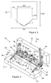
- Figure 3 of the drawings illustrate the free passage by showing the shape and maximum size of structures that can pass along the firing line of a typical pipelaying vessel.
- the inner line 32 shows the envelope of the free passage that is available through the tensioners
- the outer line 34 shows the envelope of the free passage that is available after the tensioners. Both envelopes have a V shape at the bottom, arising from the rollerboxes that support the pipe along the firing line.
- the dimensions shown in Figure 3 are merely examples for ease of understanding.
- pipeline accessories may be fitted with foldable mudmats that are overboarded in a compact folded configuration and then opened into a deployed configuration upon or before reaching the seabed.
- size and stiffness of mudmats particularly in a folded position, is not compatible with the small bending radius of the pipe on the stinger. This is a problem in S-lay operations in general but is a particular problem in Steep S-lay operations, where the radius of curvature of the stinger is smaller and the overbend strain is much greater, imparting stress in the pipe that may be very close to its yield stress.
- the accessory must be kept upright as it passes over the stinger and when it is supported mid-water in the free span of the pipe after launching from the installation vessel and before touchdown on the seabed.
- Mudmats could of course be pre-installed on the seabed, but this adds greatly to the cost and complexity of the pipelaying operation.
- the invention resides in an accessory for a subsea pipeline, the accessory comprising: a rigid pipe support frame defining a pipe course; and at least one carriage arranged to support a pipe or a fitting attached to a pipe, the carriage being movable with respect to the frame in a direction generally parallel to the pipe course.
- the invention is characterised in that the carriage is attached to the frame via at least one angularly movable connection that allows a pipe or fitting supported by the carriage to tilt locally with respect to the frame as the pipe bends during laying.
- the invention makes the pipe stiffness independent from the stiffness of the accessory.
- the stiffened section of the pipe is limited to a short length of the carriage. This is compatible with the small bending radius of the pipe on a stinger.
- the angularly movable connection decouples the rigidity of the frame from the pipe under loads in a generally vertical plane that bend the pipe during laying.
- the connection may, for example, comprise a pivot joint acting between the carriage and the frame, with a pivot axis being substantially orthogonal to the pipe course.
- the carriage should still resist movement of the pipe or fitting relative to the frame in a direction transverse to the pipe course.
- the accessory of the invention comprises at least two carriages each arranged to support a pipe or a fitting attached to a pipe, which are suitably movable in series on the frame.
- the carriages are movable independently with respect to the frame in a direction generally parallel to the pipe course.
- Each carriage is attached to the frame via at least one angularly movable connection that allows the pipe or fitting supported by the carriage to tilt with respect to the frame as the pipe bends during laying.
- the frame suitably comprises at least one rail substantially aligned with the pipe course, along which the carriage is movable.
- the frame may comprise a plurality of generally parallel longitudinal structural members, with at least one of those structural members being a rail along which the carriage is movable. More preferably, there are at least two rails with a gap between them, at least one rail being disposed to each side of a plane containing the pipe course, with the or each carriage being engaged with both rails, intersecting that plane and bridging the gap between the rails. This provides a stable and symmetrically-balanced arrangement.
- the carriage is exemplified in the following description as a bridge member extending between two rails.
- the accessory of the invention preferably further comprises a foundation to which the frame is attached, the foundation being arranged to rest on the seabed when the pipeline is laid.
- That foundation suitably comprises one or more mudmats that are movable with respect to the frame between a folded position and a deployed position.
- a mudmat is movable with respect to the frame about a pivot axis, and has a centre of gravity that is outboard of the pivot axis when in the folded position.
- the accessory further comprises a restraint, such as a rope that may be cut by an ROV, for holding the mudmat in the folded position against gravitational force.
- a restraint such as a rope that may be cut by an ROV, for holding the mudmat in the folded position against gravitational force.
- one such restraint may act on two mudmats and be capable of releasing both mudmats simultaneously for coordinated movement into the deployed position.
- the invention preferably involves simultaneously deploying foundation members from the accessory in opposed lateral directions with respect to the longitudinal axis of the pipe.
- a variable-length link is preferably provided between a mudmat and the frame to allow the mudmat to fold and to control the position of the mudmat when deployed.
- that link is preferably lockable in an extended position when a mudmat is deployed.
- a mudmat is preferably elevated above the level of the pipe course when in the folded position. The mudmat is then lowered toward the level of the pipe course in the deployed position.
- the carriage may support a pipe fitting comprising a piping branch, a connector, a valve and/or a valve actuator.
- the carriage may comprise a cradle for supporting a connector; the cradle may further support a valve actuator beside the connector.
- the accessory of the invention further comprises longitudinally-spaced rigging supports for the attachment of rigging elements to support the load of the accessory.
- the rigging supports are suitably located at or near opposed ends of the frame and are preferably located substantially in a vertical plane containing the pipe course. This arrangement avoids blocking the deployment of folding mudmats.
- those rigging elements are preferably variable in their effective length as the accessory changes in orientation during laying.
- the rigging elements may be respective ends of a cable or the like, suspended by a sheave through which the cable can pass.
- At least one of the rigging supports comprises an elongate lever that extends to an elevated position above the frame.
- the elongate lever is suitably hinged on an axis transverse to the pipe course, to pivot as orientation of the accessory changes during laying.
- the elongate lever applies stabilising leverage to the rigging element at an elevated position above the frame.
- the accessory of the invention is preferably substantially symmetrical about a vertical plane containing the pipe course.
- the pipe When a pipe extends along the pipe course of the accessory, the pipe is advantageously supported beneath the structural members of the frame. This places the pipe in the V-shaped envelope defined by rollerboxes, while maximising space available for the accessory in the firing line.
- the pipe suitably comprises at least one piping branch extending transversely with respect to the pipe. That piping branch may lead to a valve, in which case there is suitably a valve actuator for operating the valve. It is preferred that the actuator is rotatable about an axis transverse to the pipe - and more specifically that the axis of rotation of the actuator is generally vertical when the accessory is on the seabed in use - as this eases access for ROV operation.
- a gear system may be provided between the actuator and the valve to change the direction of drive torque applied to the actuator.
- the piping branch may lead to a connector.
- the piping branch, the valve and/or the connector are substantially coplanar with the pipe.
- the invention extends to a method of laying a subsea pipeline from a vessel, comprising: overboarding an accessory that is attached to a pipe directly or via a pipe fitting and that is longitudinally rigid in relation to the pipe; and causing the pipe to bend relative to the accessory about a centre of curvature above or below the pipe.
- the invention is characterised by accommodating said bending of the pipe by permitting angular movement of the pipe or the fitting where it is attached to the accessory by at least one angularly movable connection acting between the pipe or fitting and a frame of the accessory.
- the method of the invention is most advantageously practised in an S-lay operation involving bending the pipe over a stinger.
- an in-line structure in accordance with the invention - exemplified here as an ILT 36 - comprises a frame 38 to which folding mudmats 40, 42 are pivotably attached.
- the mudmats will have a surface area of about 50m 2 and will be fitted with skirts 300mm deep, but these exemplary figures are provided solely for illustration and are not limiting.
- one mudmat 40 is shown in Figures 4 to 7 in a folded position and the other mudmat 42 is shown in a deployed position.
- both mudmats 40, 42 will always adopt corresponding positions - either folded, deployed or in transition while being deployed. This is to maintain symmetry about a central vertical longitudinal plane and hence to prevent imbalance, which would apply an unwanted torque around a longitudinal axis of the ILT 36.
- the frame 38 comprises a pair of parallel longitudinal tubular rails 44 and a pair of parallel longitudinal tubular struts 46 that connect end structures 48, 50, one at each end of the frame 38.
- the end structures 48, 50 support the pair of rails 44 and the pair of struts 46 in respective planes that are parallel to each other and that also lie generally parallel to the seabed when the ILT 36 is in use.
- the plane of the rails 44 lies above the plane of the struts 46 and the horizontal spacing between the rails 44 is greater than the horizontal spacing between the struts 46.
- the cross-sectional shape of the frame 38 defined by the rails 44 and the struts 46 is an isosceles trapezium that is symmetrical about a central vertical plane.
- a pipe 12 of, for example, 10.75" (273 mm) diameter extends generally parallel to the rails 44 and the struts 46, at a central position disposed between but beneath the struts 46.
- Two longitudinally-spaced connectors 52 extend orthogonally from the pipe 12 surmounting ball valves 54 attached to the pipe 12. A spacing of 2100mm between the connectors is typical but not essential.
- Ball valve actuators 56 one beside each connector 52, have an advantageously vertical axis whereby an ROV (not shown) can more easily drive a torque tool into engagement with the actuator 56.
- a bevel gear arrangement beneath each actuator 56 transmits torque from the actuator 56 to the associated ball valve 54 disposed under the connector 52.
- Each connector 52, ball valve 54 and actuator 56 is coupled to both rails 44 via a respective bridge member 58 that spans the gap between the rails 44.
- Each connector 52, ball valve 54 and actuator 56 is also attached to the pipe 12, either directly or via a cradle 60 that is attached to both the bridge member 58 and the pipe 12.
- Each cradle 60 is oblong in plan, with the connector 52 disposed toward one end of the oblong and the associated actuator 56 disposed toward the other end of the oblong.
- a pair of parallel bearing sleeves 62 is attached to each bridge member 58, one bearing sleeve 62 being at each end of the bridge member 58.
- the bearing sleeves 62 receive the rails 44 as a sliding fit whereby the bridge members 58 may slide independently along the rails 44.
- the connectors 52, ball valves 54 and actuators 56 carried by the bridge members 58 and the cradles 60 are movable longitudinally with respect to the frame 38 and hence with respect to the mudmats 40, 42. This movement accommodates axial movement of the pipe 12 and hence of the connectors 52, ball valves 54 and actuators 56 with respect to the static parts of the ILT 36 under fluctuating thermal stresses and other axial loads on the pipe 12. Provision for pipe expansion of 1.58m including a contingency of 0.50m is typical, by way of example.
- a pivot coupling 64 acts between the bridge member 58 and the bearing sleeves 62 whereby the connectors 52, ball valves 54 and actuators 56 carried by the bridge members 58 and the cradles 60 can tilt with respect to the rails 44.
- the pivot coupling 64 of each bearing sleeve 62 defines a pivot axis that intersects and is orthogonal to the longitudinal axis of the associated rail 44.
- the pivot axis of the pivot coupling 64 is disposed centrally with respect to the length of the associated cradle 60.
- This tilting facility allows the pipe 12 to bend with respect to the rails 44 about a centre of curvature below the longitudinal axis of the pipe 12, as when a pipeline passes over a stinger in an S-lay operation as shown in Figure 11 of the drawings.
- the axes of the respective connectors 52 and ball valves 54 that are orthogonal to the pipe 12 will no longer be mutually parallel when the pipe 12 bends in that manner. Instead, their axes will diverge moving away from the centre of curvature of the pipe 12. This is why the pivot couplings 64 are necessary to allow the connectors 52, ball valves 54 and actuators 56 carried by the bridge members 58 and the cradles 60 to tilt with respect to the rails 44 as the pipe 12 bends.
- each mudmat 40, 42 is pivotably attached to the end structures 48, 50 of the frame 38 about pivot axes that extend parallel to the rails 44.
- each mudmat 40, 42 is an elongate oblong that is joined near each end to a respective end structure 48, 50 by a lower swing arm 66 and by an upper two-part articulated link 68.
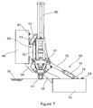
- the fixed-length swing arms 66 define the pivot axes about which the mudmats 40, 42 fold, and the articulated links 68 have variable length to control and limit the unfolding movement upon deployment. Details of the swing arms 66 and the articulated links 68 are best appreciated in the end view of Figure 7 .
- Each swing arm 66 joins an inboard edge of a mudmat 40, 42 to an end structure 48, 50 of the frame 38.
- the swing arm 66 is fixed at an outboard end to the mudmat 40, 42 and is pivotable at an inboard end about a pivot axis aligned with a strut 46 of the frame 38.
- Each articulated link 68 comprises an inner arm 70 and an outer arm 72.
- the inner arm 70 is pivotable at an inboard end about a pivot axis disposed above a rail 44 of the frame 38; at its outer end, the inner arm 70 is hinged to the outer arm 72.
- the outer arm 72 is hinged to a pivot bracket 74 affixed to the mudmat 40, 42 in longitudinal alignment with and outboard of the swing arm 66.
- the articulated links 68 of a folded mudmat 40 collapse to enable folding, whereas the articulated links 68 of a deployed mudmat 42 align to straighten and extend the links 68.
- the outer arm 72 bears against the top of the inner arm 70 when an articulated link 68 straightens as a mudmat 40, 42 is deployed, to prevent the articulated link 68 adopting an over-centre state. This locks the mudmats 40, 42 in the deployed position.
- the mudmats 40, 42 lie substantially level and coplanar with each other and with the seabed 76 upon deployment, with their skirts embedded in the seabed 76 as shown in Figure 7 .
- FIGs 4 to 7 also show a buoyancy block support 78 attached to one end structure 48 of the ILT 36 and a buoyancy block ladder 80 attached to the other end structure 50 of the ILT 36. These features are provided for attaching rigging to the ILT 36 to support its weight before landing on the seabed. Buoyancy issues will be discussed further below with reference to Figures 10 and 11 of the drawings.
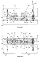
- Figures 8 and 9 of the drawings show the ILT 36 with both mudmats 40, 42 in the folded position.
- the mudmats 40, 42 are positioned high enough to be above the V-shape at the bottom of the envelope of the free passage as shown in Figure 3 .
- the structure can then go through all of the obstacles in the firing line, provided that the mudmats 40, 42, arms 66 and links 68 are added to the structure after the tensioners.
- the mudmats 40, 42 are held in the folded position by a single rope 82, so that an ROV can release both mudmats 40, 42 simultaneously simply by cutting the rope 82 at one point in a single operation upon deployment.
- a loop of rope 82 is provided. This extends through longitudinally-spaced pairs of eyes 84 provided on the upper face of each mudmat 40, 42, which faces inwardly when folded.
- the loop of rope 82 holds the mudmats 40, 42 securely in the folded position but provides easy access for cutting by an ROV upon deployment. Conveniently, the cutting point will be at the end of the ILT 36 adjacent the buoyancy block support 78.
- the pairs of eyes 84 are offset toward the corresponding end of the mudmats 40, 42 for that purpose.
- the loop of rope 82 does not clash or interfere with rigging for attachment of buoyancy, including a cable 86 as will be described in more detail below with reference to Figures 10 and 11 .
- the mudmats 40, 42 are shown here deployed just before landing on the seabed, with the ILT 36 in a near-horizontal orientation.
- the mudmats 40, 42 will self-deploy under their own weight. This is because the centre of gravity of each mudmat 40, 42 is outboard of the pivot axis defined by the associated swing arms 66. Rotation is easier to realize than a translation, and it is desirable to minimise ROV operations.
- the preferred solution described herein has only pivot links, and there is no need to connect locking arms subsea.
- a damping system may be provided to slow down the deployment of the mudmats 40, 42 if necessary.
- Figure 10 will also be used to describe buoyancy arrangements, with additional reference now to Figure 11.
- Figure 11 shows the stern of an installation vessel 88 having a stinger 90 suspended from it, the stinger 90 being arranged for Steep S-lay operations and hence imparting a near-vertical departure angle to the pipe 12 being launched from the vessel 88.
- An ILT 36 in line with the pipe 12 is shown in Figure 11 traversing the stinger 90 in two positions and orientations, one earlier position near the top of the stinger 90 where the pipe 12 is nearer horizontal, and the other later position near the bottom of the stinger 90 where the pipe 12 is nearer vertical.
- a crane (not shown) on the vessel 88 takes the weight of the ILT 36 via support rigging comprising a length of the aforementioned cable 86 that hangs from a buoy 92 via a sheave 94 as shown in Figure 11 .
- the crane lowers the buoy 92 into the water as the ILT 36 leaves the stinger 90, whereupon the buoyancy of the buoy 92 takes over to support the ILT 36 during its descent.
- the crane cable 96 may then be detached from the buoy 92.
- the buoyancy of the buoy 92 is necessary during installation for two main reasons. Firstly, it is necessary to relieve the pipe 12 of the weight of the ILT 36: the pipe 12 is not strong enough to support the presence of such a heavy structure. Consequently, buoyancy is added to set the apparent weight in water of the structure at a little above neutral, i.e. with slightly negative buoyancy. Neutral or positive buoyancy would prevent the ILT 36 from landing correctly; also, the pipe 12 could be damaged when the buoyancy is disconnected from the ILT 36. Secondly, it is necessary to ensure that the ILT 36 will land upright: the centre of gravity of the structure is above the level of the pipe 12, so the ILT 36 would turn around the pipe 12 during the descent and land upside down unless measures are taken to prevent that.
- buoyancy block support 78 attached to one end structure 48 of the ILT 36 and the buoyancy block ladder 80 attached to the other end structure 50 of the ILT 36. These features anchor and interact with the cable 86 that hangs from the buoy 92 via the sheave 94.
- One end of the cable 86 is anchored to the top of the buoyancy block support 78 and the other end of the cable 86 is anchored to the top of the buoyancy block ladder 80.
- the cable 86 is free to slide through the sheave 94 to vary the relative lengths of the inclined sections of cable 86 as the orientation of the ILT 36 changes to follow the S-curvature of the pipe 12 during overboarding and descent.
- the cable 86 is anchored to the buoyancy block support 78 at a level close to the top of the mudmats 40, 42 when folded. By virtue of this, the cable 86 does not clash with the folded mudmats 40, 42 during overboarding and descent. Nor does the cable 86 interfere with the subsequent deployment of the mudmats 40, 42.
- the point of application of stabilising side force from the cable 86 needs to be above the centre of gravity of the ILT 36 to keep the structure upright.
- the point of application needs to be as high as reasonably possible above the centre of gravity of the ILT 36 to counteract the effects of dynamic and hydrodynamic loads on the structure. This is the reason for the length of the ladder 80, which creates a large lever arm bearing against the cable 86 as high as possible to prevent rotation of the ILT 36.
- rung-like crossmembers 98 are spaced from the base of the ladder 80 to its free end as shown in Figure 10 .
- the ladder 80 is disposed at the upper or trailing end of the ILT 36 with respect to the direction of descent.
- the ladder 80 is pivotably attached at its base to the ILT 36 via a hinge 100 on the end structure 50.
- This hinge 100 is shown in the more detailed view of Figure 10 .
- the pivot axis of the hinge 100 is orthogonal to the longitudinal axis of the pipe 12.
- the ladder 80 is not free to turn about other axes with respect to the ILT 36.
- the buoyancy block support 78, the buoyancy block ladder 80, the cable 86 and the buoy 92 may be removed from the ILT 36 by an ROV.
Landscapes
- Engineering & Computer Science (AREA)
- General Engineering & Computer Science (AREA)
- Mechanical Engineering (AREA)
- Mining & Mineral Resources (AREA)
- Life Sciences & Earth Sciences (AREA)
- Geology (AREA)
- Fluid Mechanics (AREA)
- Environmental & Geological Engineering (AREA)
- Physics & Mathematics (AREA)
- General Life Sciences & Earth Sciences (AREA)
- Geochemistry & Mineralogy (AREA)
- Earth Drilling (AREA)
- Laying Of Electric Cables Or Lines Outside (AREA)
- Supports For Pipes And Cables (AREA)
Description
- This invention relates to marine pipelaying using a vessel such as a barge to lay an offshore pipeline. The invention relates particularly to pipeline accessory structures such as in-line tees, and to pipelaying systems and methods in which such structures are incorporated into a pipeline during fabrication and are then deployed on the seabed.
- In this specification, the term 'S-lay' is intended to encompass the variant Steep S-lay, as described below, unless the context requires otherwise.
- Marine pipelaying techniques that involve fabrication of a rigid pipeline on a vessel are generally categorised as either S-lay or J-lay, although variants and hybrids of those techniques have been proposed and used. Examples of S-lay and J-lay techniques involving the installation of pipeline accessories are disclosed in
GB 2465117 - The S-lay technique involves welding together successive pipe sections or 'joints' at a series of working stations in a generally horizontal firing line on the deck of a pipelaying vessel, from which the pipeline is launched into the water over a stinger. A series of tensioners grip the pipe to control its movement relative to the vessel under the load of the free span of the pipe extending between the vessel and the seabed. The pipe adopts a first 'overbend' as it passes over the stinger and a second opposed bend as it nears the seabed. These opposed bends lend an S-shape to the free span of the pipe - hence 'S-lay'.
- S-lay was first developed for shallow-water applications but S-lay techniques designed for shallow-water pipelaying are not suitable for pipelaying in deep and ultradeep water. The J-lay technique is usually preferred when pipelaying in such depths, particularly with wider pipes. J-lay involves welding single or multiple pipe joints onto the pipe end in an upright (i.e. substantially vertical or near-vertical) orientation in a J-lay tower on a pipelaying vessel. The pipe is launched downwardly into the water as it is formed. The pipe adopts a single bend as it nears the seabed to lend a J-shape to the free span of the pipe - hence 'J-lay'.
- S-lay benefits from a long production line with several working stations, and hence speeds the pipe fabrication process. Thus, where it can be used, S-lay is often preferred to J-lay for its inherently greater lay rate. Recently, this has led to the development of a variant of S-lay known as 'Steep S-lay', which is adapted for deep and ultradeep water applications where the pipe diameter allows. As the name suggests, Steep S-lay involves setting the lift-off point of the pipe from the stinger as close to vertical as possible. Thus, the pipe experiences a substantial overbend strain in a Steep S-lay operation, undergoing a deflection through substantially 90 degrees as it passes over the stinger.
- To provide operational flexibility, to create desired field layouts and to support future field extensions, pipelines are commonly fitted with accessories, both at the ends of the pipeline and within it. These accessories can include in-line tees, PLEMs, PLETs, tie-in branches, shutdown valves, pigging connections and other subsea structures.
- To describe the prior art and to provide further background to the present invention, reference will now be made to
Figures 1 to 3 of the accompanying drawings, in which: -
Figure 1 is a schematic perspective view showing a typical location of an in-line tee in a subsea oilfield; -
Figure 2 is a perspective view of an in-line tee of the prior art; and -
Figure 3 is a diagram illustrating typical cross-sectional envelopes that are available for structures to pass along the firing line of a pipelaying vessel. - The invention will be exemplified in this specification with reference to an in-line tee or ILT. An ILT is a transition device that is used on pipelines and flowlines carrying production oil/gas or water injection fluids. The ILT is a subsea hub for connection to another system, which may be a manifold, a wellhead or a PLET. In this respect, reference is made by way of example to
Figure 1 which shows anILT 10 in use on aflowline pipe 12 beside asubsea wellhead 14. The ILT 10 is installed directly in line with thepipe 12. The connection between the ILT 10 and thewellhead 14 is made via a subsea jumper/spool 16. The main functional parts of theILT 10 are a connector to connect the jumper/spool 16 to thepipe 12, and a valve to control the flow through the connector. - An ILT may have more than one
connector 18 and more than onevalve 20, as shown in the prior artdouble ILT 22 ofFigure 2 which is adapted for water injection. TheILT 22 shown inFigure 2 further comprises amudmat 24 surrounded by aperipheral skirt 26, surmounted byparallel rails 28 on which a slidingframe 30 can move longitudinally with respect to themudmat 24. Theframe 30 supports theconnectors 18 andvalves 20 and also supports thepipe 12 to which theconnectors 18 are attached. Theframe 30 may also support instrumentation devices, but these are not shown inFigure 2 . - The ILT 22 must support hardware attached to the
pipe 12, such asconnectors 18 and pipe branches, and must resist rotation and lateral movement while also avoiding excessive settlement into the seabed. The weight of the ILT 22 must not be supported by thepipe 12 itself once on the seabed, but must instead be supported by themudmat 24. Themudmat 24 has to cope with the high centre of gravity of theILT 10 and the torque applied by the laterally-offset jumper/spool 16, while keeping theILT 22 and thepipe 12 stable without becoming embedded in the mud of the seabed. - For this purpose, the
mudmat 24 is long and wide to define a large base area, particularly when used in deep water where the seabed is often very soft. Theskirt 26 digs into in the seabed to prevent themudmat 24 from moving and the structure from becoming embedded. Thus, theskirt 26 locates themudmat 24 against lateral or axial movement relative to the seabed. - As the fluids that pass through the
pipe 12 in use are typically hot (circa 70-250 Celsius for oil and circa 30-60 Celsius for injected water), the length of thepipe 12 can vary considerably when the flow starts or stops. Pipe expansion must be permitted by the ILT 22 in order to avoid over-stressing thepipe 12 and causing cracks or buckling. Conservatively thepipe 12 may move axially by 500mm even when little expansion is expected, but thepipe 12 may move by up to several metres in applications carrying hot fluids. This is why an ILT 22 that has itsmudmat 24 fitted with askirt 26 needs to have a slidingframe 30 movable longitudinally onrails 28, to allow the pipe 12 (and theconnectors 18,valves 20, pipe branches and other elements carried by the sliding frame 30) to move axially relative to thefixed mudmat 24. - Clearly, pipeline installation is not solely a pipelaying activity but it also involves handling and lowering large accessories such as ILTs attached to the pipe. Consequently, the overall speed of pipeline installation is not determined simply by the rate at which a vessel can lay pipe, but also by the ability of the vessel to install accessories as part of the pipeline. In this respect, a weakness of S-lay is the integration of large accessories with the pipeline, which may need to be installed over the side of the vessel and hence interrupt the laying operation. J-lay is better suited than S-lay to adding such accessories to the pipeline, which tends to offset the inherently greater lay rate of S-lay.
- To ease the integration of large accessories in S-lay operations, a solution is to pass only a part of the accessory structure through open tensioners of a pipelaying vessel, and then to assemble the full structure after or downstream of the tensioners. However, there is clearly a limit to the size of structure that may pass through the tensioners; also, the deck layout of the vessel may impose space constraints after the tensioners.
- The effect of such constraints is shown in
Figure 3 of the drawings, which illustrate the free passage by showing the shape and maximum size of structures that can pass along the firing line of a typical pipelaying vessel. Theinner line 32 shows the envelope of the free passage that is available through the tensioners, and theouter line 34 shows the envelope of the free passage that is available after the tensioners. Both envelopes have a V shape at the bottom, arising from the rollerboxes that support the pipe along the firing line. The dimensions shown inFigure 3 are merely examples for ease of understanding. - To address these space constraints, pipeline accessories may be fitted with foldable mudmats that are overboarded in a compact folded configuration and then opened into a deployed configuration upon or before reaching the seabed. However, the size and stiffness of mudmats, particularly in a folded position, is not compatible with the small bending radius of the pipe on the stinger. This is a problem in S-lay operations in general but is a particular problem in Steep S-lay operations, where the radius of curvature of the stinger is smaller and the overbend strain is much greater, imparting stress in the pipe that may be very close to its yield stress.
- There is also the problem of controlling the orientation of the accessory during pipelaying. The accessory must be kept upright as it passes over the stinger and when it is supported mid-water in the free span of the pipe after launching from the installation vessel and before touchdown on the seabed.
- There is also a need to ensure easy access for the connection of jumpers to the accessory after deployment.
- Mudmats could of course be pre-installed on the seabed, but this adds greatly to the cost and complexity of the pipelaying operation.
- It is against this background that the present invention has been devised.
- In one sense, the invention resides in an accessory for a subsea pipeline, the accessory comprising: a rigid pipe support frame defining a pipe course; and at least one carriage arranged to support a pipe or a fitting attached to a pipe, the carriage being movable with respect to the frame in a direction generally parallel to the pipe course. In relation to the prior art acknowledged above, the invention is characterised in that the carriage is attached to the frame via at least one angularly movable connection that allows a pipe or fitting supported by the carriage to tilt locally with respect to the frame as the pipe bends during laying.
- The invention makes the pipe stiffness independent from the stiffness of the accessory. The stiffened section of the pipe is limited to a short length of the carriage. This is compatible with the small bending radius of the pipe on a stinger. More specifically, therefore, the angularly movable connection decouples the rigidity of the frame from the pipe under loads in a generally vertical plane that bend the pipe during laying. The connection may, for example, comprise a pivot joint acting between the carriage and the frame, with a pivot axis being substantially orthogonal to the pipe course.
- To locate the pipe, the carriage should still resist movement of the pipe or fitting relative to the frame in a direction transverse to the pipe course.
- To cater for accessories such as double ILTs, it is preferred that the accessory of the invention comprises at least two carriages each arranged to support a pipe or a fitting attached to a pipe, which are suitably movable in series on the frame. The carriages are movable independently with respect to the frame in a direction generally parallel to the pipe course. Each carriage is attached to the frame via at least one angularly movable connection that allows the pipe or fitting supported by the carriage to tilt with respect to the frame as the pipe bends during laying.
- The frame suitably comprises at least one rail substantially aligned with the pipe course, along which the carriage is movable. For example, the frame may comprise a plurality of generally parallel longitudinal structural members, with at least one of those structural members being a rail along which the carriage is movable. More preferably, there are at least two rails with a gap between them, at least one rail being disposed to each side of a plane containing the pipe course, with the or each carriage being engaged with both rails, intersecting that plane and bridging the gap between the rails. This provides a stable and symmetrically-balanced arrangement. The carriage is exemplified in the following description as a bridge member extending between two rails.
- The accessory of the invention preferably further comprises a foundation to which the frame is attached, the foundation being arranged to rest on the seabed when the pipeline is laid. That foundation suitably comprises one or more mudmats that are movable with respect to the frame between a folded position and a deployed position.
- In an advantageously simple arrangement, a mudmat is movable with respect to the frame about a pivot axis, and has a centre of gravity that is outboard of the pivot axis when in the folded position. This allows the mudmat to deploy under its own weight when released. It is therefore preferred that the accessory further comprises a restraint, such as a rope that may be cut by an ROV, for holding the mudmat in the folded position against gravitational force. Elegantly, one such restraint may act on two mudmats and be capable of releasing both mudmats simultaneously for coordinated movement into the deployed position. Thus, the invention preferably involves simultaneously deploying foundation members from the accessory in opposed lateral directions with respect to the longitudinal axis of the pipe.
- A variable-length link is preferably provided between a mudmat and the frame to allow the mudmat to fold and to control the position of the mudmat when deployed. For stability, that link is preferably lockable in an extended position when a mudmat is deployed.
- To avoid obstructions beside the firing line on a vessel, a mudmat is preferably elevated above the level of the pipe course when in the folded position. The mudmat is then lowered toward the level of the pipe course in the deployed position.
- The carriage may support a pipe fitting comprising a piping branch, a connector, a valve and/or a valve actuator. The carriage may comprise a cradle for supporting a connector; the cradle may further support a valve actuator beside the connector.
- Advantageously, the accessory of the invention further comprises longitudinally-spaced rigging supports for the attachment of rigging elements to support the load of the accessory. The rigging supports are suitably located at or near opposed ends of the frame and are preferably located substantially in a vertical plane containing the pipe course. This arrangement avoids blocking the deployment of folding mudmats.
- Where rigging elements are attached to the rigging supports, those rigging elements are preferably variable in their effective length as the accessory changes in orientation during laying. For example, the rigging elements may be respective ends of a cable or the like, suspended by a sheave through which the cable can pass.
- To resist rotation of the accessory with respect to a rigging element, it is preferred that at least one of the rigging supports comprises an elongate lever that extends to an elevated position above the frame. The elongate lever is suitably hinged on an axis transverse to the pipe course, to pivot as orientation of the accessory changes during laying. The elongate lever applies stabilising leverage to the rigging element at an elevated position above the frame.
- In general, the accessory of the invention is preferably substantially symmetrical about a vertical plane containing the pipe course.
- When a pipe extends along the pipe course of the accessory, the pipe is advantageously supported beneath the structural members of the frame. This places the pipe in the V-shaped envelope defined by rollerboxes, while maximising space available for the accessory in the firing line.
- The pipe suitably comprises at least one piping branch extending transversely with respect to the pipe. That piping branch may lead to a valve, in which case there is suitably a valve actuator for operating the valve. It is preferred that the actuator is rotatable about an axis transverse to the pipe - and more specifically that the axis of rotation of the actuator is generally vertical when the accessory is on the seabed in use - as this eases access for ROV operation. Thus, a gear system may be provided between the actuator and the valve to change the direction of drive torque applied to the actuator.
- It is also possible for the piping branch to lead to a connector. For compactness, it is preferred that the piping branch, the valve and/or the connector are substantially coplanar with the pipe. There may be two such piping branches extending transversely with respect to the pipe, and those piping branches may diverge or converge as the pipe bends during laying within a plane that contains the piping branches and the pipe.
- Within the inventive concept, the invention extends to a method of laying a subsea pipeline from a vessel, comprising: overboarding an accessory that is attached to a pipe directly or via a pipe fitting and that is longitudinally rigid in relation to the pipe; and causing the pipe to bend relative to the accessory about a centre of curvature above or below the pipe. The invention is characterised by accommodating said bending of the pipe by permitting angular movement of the pipe or the fitting where it is attached to the accessory by at least one angularly movable connection acting between the pipe or fitting and a frame of the accessory. The method of the invention is most advantageously practised in an S-lay operation involving bending the pipe over a stinger.
- Reference has already been made to
Figures 1 to 3 of the accompanying drawings to provide background to the present invention. In order that the invention may be more readily understood, reference will now be made, by way of example, to the remaining drawings in which: -
Figure 4 is a perspective view of an ILT in accordance with the invention having two folding mudmats, with one mudmat shown in a folded position and the other mudmat shown in a deployed position; -
Figure 5 is a side view of the ILT ofFigure 4 , in the direction of arrow V ofFigure 4 ; -
Figure 6 is a top plan view of the ILT ofFigures 4 and5 , in the direction of arrow VI ofFigure 4 ; -
Figure 7 is an end view of the ILT ofFigures 4 to 6 , in the direction of arrow VII ofFigure 4 ; -
Figure 8 is an end view of the ILT ofFigures 4 to 7 , but showing both mudmats in the folded position; -
Figure 9 is a perspective view of the ILT ofFigure 8 ; -
Figure 10 is a perspective view of the ILT ofFigures 8 and 9 but with both mudmats now unfolded into the deployed position, ready to be landed on the seabed; and -
Figure 11 is a schematic side view of the ILT ofFigures 8 and 9 with folded mudmats being overboarded from a pipelaying vessel in a Steep S-lay operation, as part of a pipeline curving along a stinger. - Referring firstly to
Figures 4 to 7 of the drawings, an in-line structure in accordance with the invention - exemplified here as an ILT 36 - comprises aframe 38 to whichfolding mudmats - For the purpose of illustration, one
mudmat 40 is shown inFigures 4 to 7 in a folded position and theother mudmat 42 is shown in a deployed position. However, in practice, bothmudmats ILT 36. - The
frame 38 comprises a pair of parallel longitudinaltubular rails 44 and a pair of parallel longitudinal tubular struts 46 that connectend structures frame 38. Theend structures rails 44 and the pair ofstruts 46 in respective planes that are parallel to each other and that also lie generally parallel to the seabed when theILT 36 is in use. The plane of therails 44 lies above the plane of thestruts 46 and the horizontal spacing between therails 44 is greater than the horizontal spacing between thestruts 46. The cross-sectional shape of theframe 38 defined by therails 44 and thestruts 46 is an isosceles trapezium that is symmetrical about a central vertical plane. - A
pipe 12 of, for example, 10.75" (273 mm) diameter extends generally parallel to therails 44 and thestruts 46, at a central position disposed between but beneath thestruts 46. Two longitudinally-spacedconnectors 52 extend orthogonally from thepipe 12 surmountingball valves 54 attached to thepipe 12. A spacing of 2100mm between the connectors is typical but not essential.Ball valve actuators 56, one beside eachconnector 52, have an advantageously vertical axis whereby an ROV (not shown) can more easily drive a torque tool into engagement with theactuator 56. To enable this orientation of the actuator axis, a bevel gear arrangement beneath each actuator 56 transmits torque from theactuator 56 to the associatedball valve 54 disposed under theconnector 52. - Referring back to
Figure 3 , it will be recalled that the rollerboxes along the firing line impart a V shape to the envelope at the bottom of the free passage through and after the tensioners. It follows that the branch piping of, for example, 6" (150 mm) diameter leading from thepipe 12 to theball valves 54 andconnectors 52 cannot be too close to the horizontal if it is to remain inside the V. Hence it is advantageous to place the branch piping,ball valves 54 andconnectors 52 vertically above thepipe 12. This also avoids the use of elbows, which saves cost. - Each
connector 52,ball valve 54 andactuator 56 is coupled to bothrails 44 via arespective bridge member 58 that spans the gap between therails 44. Eachconnector 52,ball valve 54 andactuator 56 is also attached to thepipe 12, either directly or via acradle 60 that is attached to both thebridge member 58 and thepipe 12. Eachcradle 60 is oblong in plan, with theconnector 52 disposed toward one end of the oblong and the associatedactuator 56 disposed toward the other end of the oblong. - A pair of
parallel bearing sleeves 62 is attached to eachbridge member 58, one bearingsleeve 62 being at each end of thebridge member 58. The bearingsleeves 62 receive therails 44 as a sliding fit whereby thebridge members 58 may slide independently along therails 44. Thus, theconnectors 52,ball valves 54 andactuators 56 carried by thebridge members 58 and thecradles 60 are movable longitudinally with respect to theframe 38 and hence with respect to themudmats pipe 12 and hence of theconnectors 52,ball valves 54 andactuators 56 with respect to the static parts of theILT 36 under fluctuating thermal stresses and other axial loads on thepipe 12. Provision for pipe expansion of 1.58m including a contingency of 0.50m is typical, by way of example. - A
pivot coupling 64 acts between thebridge member 58 and the bearingsleeves 62 whereby theconnectors 52,ball valves 54 andactuators 56 carried by thebridge members 58 and thecradles 60 can tilt with respect to therails 44. For this purpose, thepivot coupling 64 of each bearingsleeve 62 defines a pivot axis that intersects and is orthogonal to the longitudinal axis of the associatedrail 44. Also, the pivot axis of thepivot coupling 64 is disposed centrally with respect to the length of the associatedcradle 60. - This tilting facility allows the
pipe 12 to bend with respect to therails 44 about a centre of curvature below the longitudinal axis of thepipe 12, as when a pipeline passes over a stinger in an S-lay operation as shown inFigure 11 of the drawings. In this respect, it will be understood that the axes of therespective connectors 52 andball valves 54 that are orthogonal to thepipe 12 will no longer be mutually parallel when thepipe 12 bends in that manner. Instead, their axes will diverge moving away from the centre of curvature of thepipe 12. This is why thepivot couplings 64 are necessary to allow theconnectors 52,ball valves 54 andactuators 56 carried by thebridge members 58 and thecradles 60 to tilt with respect to therails 44 as thepipe 12 bends. - It will also be apparent that when the axes of the
connectors 52 andball valves 54 diverge in the manner specified above, the spacing between those axes will widen where they intersect the plane of therails 44. This is why it is necessary for thebridge members 58 and thecradles 60 to be movable independently along therails 44. However, at least one of thebridge members 58 may be temporarily locked to therails 44 to locate theframe 38 of theILT 36 with respect to thepipe 12 during deployment. - The
mudmats end structures frame 38 about pivot axes that extend parallel to therails 44. Specifically, each mudmat 40, 42 is an elongate oblong that is joined near each end to arespective end structure lower swing arm 66 and by an upper two-part articulatedlink 68. The fixed-length swing arms 66 define the pivot axes about which themudmats links 68 have variable length to control and limit the unfolding movement upon deployment. Details of theswing arms 66 and the articulatedlinks 68 are best appreciated in the end view ofFigure 7 . - Each
swing arm 66 joins an inboard edge of amudmat end structure frame 38. Theswing arm 66 is fixed at an outboard end to themudmat strut 46 of theframe 38. - Each articulated
link 68 comprises aninner arm 70 and anouter arm 72. Theinner arm 70 is pivotable at an inboard end about a pivot axis disposed above arail 44 of theframe 38; at its outer end, theinner arm 70 is hinged to theouter arm 72. Theouter arm 72, in turn, is hinged to apivot bracket 74 affixed to themudmat swing arm 66. - Thus, the articulated
links 68 of a foldedmudmat 40 collapse to enable folding, whereas the articulatedlinks 68 of a deployedmudmat 42 align to straighten and extend thelinks 68. Theouter arm 72 bears against the top of theinner arm 70 when an articulatedlink 68 straightens as amudmat link 68 adopting an over-centre state. This locks themudmats mudmats seabed 76 upon deployment, with their skirts embedded in theseabed 76 as shown inFigure 7 . -
Figures 4 to 7 also show abuoyancy block support 78 attached to oneend structure 48 of theILT 36 and abuoyancy block ladder 80 attached to theother end structure 50 of theILT 36. These features are provided for attaching rigging to theILT 36 to support its weight before landing on the seabed. Buoyancy issues will be discussed further below with reference toFigures 10 and11 of the drawings. - Moving on initially to
Figures 8 and 9 of the drawings, these show theILT 36 with bothmudmats mudmats Figure 3 . The structure can then go through all of the obstacles in the firing line, provided that themudmats arms 66 andlinks 68 are added to the structure after the tensioners. - The
mudmats single rope 82, so that an ROV can release bothmudmats rope 82 at one point in a single operation upon deployment. Preferably, as shown inFigures 8 and 9 , a loop ofrope 82 is provided. This extends through longitudinally-spaced pairs ofeyes 84 provided on the upper face of each mudmat 40, 42, which faces inwardly when folded. - The loop of
rope 82 holds themudmats ILT 36 adjacent thebuoyancy block support 78. The pairs ofeyes 84 are offset toward the corresponding end of themudmats rope 82 does not clash or interfere with rigging for attachment of buoyancy, including acable 86 as will be described in more detail below with reference toFigures 10 and11 . - Referring now to
Figure 10 , themudmats ILT 36 in a near-horizontal orientation. Once therope 82 shown inFigures 8 and 9 is cut by an ROV, themudmats swing arms 66. Rotation is easier to realize than a translation, and it is desirable to minimise ROV operations. Thus, the preferred solution described herein has only pivot links, and there is no need to connect locking arms subsea. A damping system may be provided to slow down the deployment of themudmats -
Figure 10 will also be used to describe buoyancy arrangements, with additional reference now toFigure 11. Figure 11 shows the stern of aninstallation vessel 88 having astinger 90 suspended from it, thestinger 90 being arranged for Steep S-lay operations and hence imparting a near-vertical departure angle to thepipe 12 being launched from thevessel 88. - An
ILT 36 in line with thepipe 12 is shown inFigure 11 traversing thestinger 90 in two positions and orientations, one earlier position near the top of thestinger 90 where thepipe 12 is nearer horizontal, and the other later position near the bottom of thestinger 90 where thepipe 12 is nearer vertical. A crane (not shown) on thevessel 88 takes the weight of theILT 36 via support rigging comprising a length of theaforementioned cable 86 that hangs from abuoy 92 via asheave 94 as shown inFigure 11 . The crane lowers thebuoy 92 into the water as theILT 36 leaves thestinger 90, whereupon the buoyancy of thebuoy 92 takes over to support theILT 36 during its descent. Thecrane cable 96 may then be detached from thebuoy 92. - The buoyancy of the
buoy 92 is necessary during installation for two main reasons. Firstly, it is necessary to relieve thepipe 12 of the weight of the ILT 36: thepipe 12 is not strong enough to support the presence of such a heavy structure. Consequently, buoyancy is added to set the apparent weight in water of the structure at a little above neutral, i.e. with slightly negative buoyancy. Neutral or positive buoyancy would prevent theILT 36 from landing correctly; also, thepipe 12 could be damaged when the buoyancy is disconnected from theILT 36. Secondly, it is necessary to ensure that theILT 36 will land upright: the centre of gravity of the structure is above the level of thepipe 12, so theILT 36 would turn around thepipe 12 during the descent and land upside down unless measures are taken to prevent that. - Mention has already been made of the
buoyancy block support 78 attached to oneend structure 48 of theILT 36 and thebuoyancy block ladder 80 attached to theother end structure 50 of theILT 36. These features anchor and interact with thecable 86 that hangs from thebuoy 92 via thesheave 94. One end of thecable 86 is anchored to the top of thebuoyancy block support 78 and the other end of thecable 86 is anchored to the top of thebuoyancy block ladder 80. However, thecable 86 is free to slide through thesheave 94 to vary the relative lengths of the inclined sections ofcable 86 as the orientation of theILT 36 changes to follow the S-curvature of thepipe 12 during overboarding and descent. - The
cable 86 is anchored to thebuoyancy block support 78 at a level close to the top of themudmats cable 86 does not clash with the foldedmudmats cable 86 interfere with the subsequent deployment of themudmats - In principle, the point of application of stabilising side force from the
cable 86 needs to be above the centre of gravity of theILT 36 to keep the structure upright. In practice, the point of application needs to be as high as reasonably possible above the centre of gravity of theILT 36 to counteract the effects of dynamic and hydrodynamic loads on the structure. This is the reason for the length of theladder 80, which creates a large lever arm bearing against thecable 86 as high as possible to prevent rotation of theILT 36. - To increase the stiffness of the
ladder 80, rung-like crossmembers 98 are spaced from the base of theladder 80 to its free end as shown inFigure 10 . - As
Figure 11 shows, theladder 80 is disposed at the upper or trailing end of theILT 36 with respect to the direction of descent. To accommodate changes in the orientation of theILT 36 during overboarding and descent, theladder 80 is pivotably attached at its base to theILT 36 via ahinge 100 on theend structure 50. Thishinge 100 is shown in the more detailed view ofFigure 10 . The pivot axis of thehinge 100 is orthogonal to the longitudinal axis of thepipe 12. To resist rotation of theILT 36 during deployment, theladder 80 is not free to turn about other axes with respect to theILT 36. - Once the
ILT 36 has been deployed on the seabed as described above, thebuoyancy block support 78, thebuoyancy block ladder 80, thecable 86 and thebuoy 92 may be removed from theILT 36 by an ROV.
Claims (26)
- An accessory (36) for a subsea pipeline, the accessory (36) comprising:a rigid pipe support frame (38) defining a pipe course; andat least one carriage (58) arranged to support a pipe (12) or a fitting attached to a pipe (12), the carriage (58) being movable with respect to the frame (38) in a direction generally parallel to the pipe course;characterised in that at least one angularly movable connection (52) acting between the pipe (12) or fitting and the frame (38) allows a pipe (12) or fitting supported by the carriage (58) to tilt locally with respect to the frame (38) as the pipe (12) bends during laying.
- The accessory (36) of Claim 1, wherein the carriage (58) is attached to the frame (38) via the angularly movable connection (52).
- The accessory (36) of Claim 1 or Claim 2, wherein the connection (52) decouples the rigidity of the frame (38) from the pipe (12) under loads in a generally vertical plane that bend the pipe (12) during laying.
- The accessory (36) of any preceding claim, wherein the connection (52) comprises a pivot joint (64) acting between the carriage (58) and the frame (38).
- The accessory (36) of any preceding claim and comprising at least two carriages (58) each arranged to support a pipe (12) or a fitting attached to a pipe (12), the carriages (58) being movable independently with respect to the frame (38) in a direction generally parallel to the pipe course and each being attached to the frame (38) via at least one angularly movable connection (52) that allows the pipe (12) or fitting supported by the carriage (58) to tilt with respect to the frame (38) as the pipe (12) bends during laying.
- The accessory (36) of any preceding claim, wherein the frame (38) comprises a plurality of generally parallel longitudinal structural members (44, 46), at least one of those structural members (44, 46) being a rail along which the carriage (58) is movable.
- The accessory (36) of any preceding claim, further comprising a foundation to which the frame (38) is attached, the foundation being arranged to rest on the seabed when the pipeline is laid.
- The accessory (36) of Claim 7, wherein the foundation comprises one or more mudmats (40, 42) movable with respect to the frame (38) between a folded position and a deployed position.
- The accessory (36) of Claim 8, wherein a mudmat (40, 42) is movable with respect to the frame (38) about a pivot axis and has a centre of gravity that is outboard of the pivot axis when in the folded position.
- The accessory (36) of Claim 9, and further comprising a restraint (82) for holding the mudmats (40, 42) in the folded position against gravitational force acting to move the mudmats (40, 42) into the deployed position.
- The accessory (36) of Claim 10, wherein the restraint (82) acts on at least two mudmats (40, 42) and is capable of releasing both mudmats (40, 42) simultaneously for coordinated movement into the deployed position.
- The accessory (36) of any of Claims 8 to 11, wherein in the folded position, a mudmat (40, 42) is elevated above the level of the pipe course and in the deployed position, a mudmat (40, 42) is lowered toward the level of the pipe course.
- The accessory (36) of any preceding claim, wherein the fitting comprises a piping branch, a connector, a valve and/or a valve actuator.
- The accessory (36) of any preceding claim, further comprising longitudinally-spaced rigging supports (78, 80) for the attachment of rigging elements to support the load of the accessory (36).
- The accessory (36) of Claim 14, further comprising rigging elements attached to the rigging supports (78, 80), the rigging elements being variable in their effective length as orientation of the accessory (36) changes during laying.
- The accessory (36) of Claim 14 or Claim 15, wherein at least one of the rigging supports (78, 80) comprises an elongate lever (80) that extends to an elevated position above the frame (38) to resist rotation of the accessory (36) with respect to the rigging element.
- The accessory (36) of Claim 16, wherein the elongate lever (80) is hinged on an axis transverse to the pipe course, to pivot as orientation of the accessory (36) changes during laying.
- The accessory (36) of any preceding claim, further including a pipe (12) extending along the pipe course.
- A method of laying a subsea pipeline from a vessel, comprising:overboarding an accessory (36) that is attached to a pipe (12) directly or via a pipe fitting and that is longitudinally rigid in relation to the pipe (12), the pipe (12) being movable longitudinally with respect to the accessory (36) when laid; andcausing the pipe (12) to bend about a centre of curvature above or below the pipe (12);characterised by accommodating said bending of the pipe (12) by permitting angular movement of the pipe (12) or the fitting where it is attached to the accessory (36), by at least one angularly movable connection (52) acting between the pipe (12) or fitting and a frame (38) of the accessory (36).
- The method of Claim 19, where the pipe (12) is attached to the accessory (36) directly or via a pipe fitting at two or more longitudinally-spaced locations, at each of which locations angular movement of the pipe (12) or the fitting relative to the accessory (36) is permitted.
- The method of Claim 19 or Claim 20, further comprising permitting longitudinal movement of the pipe (12) or the fitting relative to the accessory (36) in a direction parallel to the longitudinal axis of the pipe (12).
- A method of any of Claims 19 to 21, further comprising supporting the load of the accessory (36) with rigging elements attached to the accessory (36) at longitudinally-spaced locations.
- The method of Claim 22, comprising varying the effective length of the rigging elements as orientation of the accessory (36) changes during laying.
- The method of Claim 22 or Claim 23, comprising applying stabilising leverage to a rigging element at an elevated position above the accessory (36).
- The method of any of Claims 19 to 24, comprising simultaneously deploying foundation members from the accessory (36) in opposed lateral directions with respect to the longitudinal axis of the pipe (12).
- The method of any of Claims 19 to 25, when practised in an S-lay operation involving bending the pipe (12) over a stinger (90).
Applications Claiming Priority (2)
| Application Number | Priority Date | Filing Date | Title |
|---|---|---|---|
| GB1101508.8A GB2487578B (en) | 2011-01-28 | 2011-01-28 | Improvements relating to pipelaying |
| PCT/IB2012/000360 WO2012101525A1 (en) | 2011-01-28 | 2012-01-24 | Improvements relating to pipelaying |
Publications (2)
| Publication Number | Publication Date |
|---|---|
| EP2668426A1 EP2668426A1 (en) | 2013-12-04 |
| EP2668426B1 true EP2668426B1 (en) | 2016-08-03 |
Family
ID=43824752
Family Applications (1)
| Application Number | Title | Priority Date | Filing Date |
|---|---|---|---|
| EP12709696.4A Active EP2668426B1 (en) | 2011-01-28 | 2012-01-24 | Improvements relating to pipelaying |
Country Status (4)
| Country | Link |
|---|---|
| US (1) | US9068675B2 (en) |
| EP (1) | EP2668426B1 (en) |
| GB (1) | GB2487578B (en) |
| WO (1) | WO2012101525A1 (en) |
Families Citing this family (24)
| Publication number | Priority date | Publication date | Assignee | Title |
|---|---|---|---|---|
| GB2478548B (en) * | 2010-03-09 | 2015-11-25 | Acergy France SAS | Apparatus and method for installing a pipeline structure at sea |
| GB2511500B (en) | 2013-03-04 | 2015-05-13 | Subsea 7 Ltd | Improvements relating to pipelaying |
| GB2515506B (en) * | 2013-06-25 | 2015-11-25 | Acergy France SAS | Foundations for subsea pipeline accessories |
| ITMI20141880A1 (en) * | 2014-11-03 | 2016-05-03 | Saipem Spa | SUPPORT FOR UNDERWATER PIPE, SYSTEM AND METHOD FOR ARRANGING THIS SUPPORT |
| US9797526B2 (en) * | 2015-09-16 | 2017-10-24 | Ge Oil & Gas Uk Limited | Riser assembly and method of installing a riser assembly |
| CN105333227B (en) * | 2015-11-11 | 2017-04-12 | 哈尔滨工程大学 | Structure support device for treating suspended span of submarine pipeline |
| GB2549102A (en) | 2016-04-04 | 2017-10-11 | Forsys Subsea Ltd | Pipeline integrated manifold |
| CN105937367B (en) * | 2016-06-15 | 2018-11-30 | 凯盛重工有限公司 | A kind of protective net of monorail crane hydraulic drill rig pumping plant |
| GB2557604B (en) * | 2016-12-09 | 2019-11-06 | Subsea 7 Do Brasil Servicos Ltda | In-line accessory for a subsea pipeline |
| GB2564138B (en) | 2017-07-04 | 2020-03-11 | Acergy France SAS | Subsea manifolds |
| NO344586B1 (en) * | 2017-12-15 | 2020-02-03 | Vetco Gray Scandinavia As | Subsea arrangement adapted for continuous installation of multiple subsea functional lines |
| GB2576128B (en) * | 2017-12-22 | 2022-08-10 | Equinor Energy As | Interconnection of subsea pipelines and structures |
| NL2020307B1 (en) * | 2018-01-23 | 2019-07-30 | Bluemarine Offshore Yard Service Bv | Subsea pipeline integrated structure |
| GB2572163B (en) * | 2018-03-20 | 2021-01-06 | Equinor Energy As | Subsea hydrocarbon production system |
| NO347147B1 (en) * | 2018-06-04 | 2023-06-05 | Vetco Gray Scandinavia As | 2-slot inline block manifold system |
| GB201901257D0 (en) * | 2019-01-30 | 2019-03-20 | Enpro Subsea Ltd | Apparatus, systems and methods for oil and gas operations |
| GB2584099B (en) | 2019-05-20 | 2021-10-20 | Equinor Energy As | Direct tie-in of subsea conduits and structures |
| GB2584855B (en) * | 2019-06-17 | 2021-10-13 | Subsea 7 Norway As | Subsea foundations |
| NO345442B1 (en) * | 2019-07-01 | 2021-02-01 | Vetco Gray Scandinavia As | Two flow, subsea, hydrocarbon fluid flow path connecting concentric hub and use of such a hub |
| NO347159B1 (en) * | 2019-07-01 | 2023-06-12 | Vetco Gray Scandinavia As | Vertical branch inline manifold system |
| CN111237542A (en) * | 2020-01-02 | 2020-06-05 | 海洋石油工程股份有限公司 | Deepwater gas field underwater connection expansion equipment for J-shaped installation |
| CN111207245A (en) * | 2020-01-16 | 2020-05-29 | 海洋石油工程股份有限公司 | Self-locking foldable submarine pipeline terminal |
| CN111649178A (en) * | 2020-03-02 | 2020-09-11 | 海洋石油工程股份有限公司 | Topside mounted subsea pipeline termination |
| CN115451186A (en) * | 2022-08-10 | 2022-12-09 | 海洋石油工程股份有限公司 | Integrally mounted split slidable subsea pipeline terminal |
Family Cites Families (15)
| Publication number | Priority date | Publication date | Assignee | Title |
|---|---|---|---|---|
| US2188243A (en) * | 1937-11-24 | 1940-01-23 | Johnson James Stanley | Irrigation system |
| US3160385A (en) * | 1961-09-21 | 1964-12-08 | Greenawalt Sintering Co Inc | Suction valve for sintering machine |
| US3204417A (en) * | 1963-10-28 | 1965-09-07 | Gunther And Shirley Company | Underwater pipe laying apparatus |
| GB1152220A (en) * | 1966-12-20 | 1969-05-14 | Land & Marine Contractors Ltd | Improvements in and relating to the Laying of Underwater Pipe Lines |
| US4028903A (en) * | 1975-11-12 | 1977-06-14 | Hydrotech International, Inc. | Method and apparatus for maneuvering pipe ends in a subsea location |
| US4268190A (en) * | 1977-10-14 | 1981-05-19 | Tesson Prosper A | Pipe handling method and apparatus |
| SE8700748L (en) * | 1986-02-24 | 1987-08-25 | Norwegian Contractors | DEVICE AND PROCEDURES FOR SUPPORT, PROTECTION AND TRANSPORTATION OF SEA OR SEA BATTERY INSTALLED PIPES |
| NL192628C (en) * | 1988-11-07 | 1997-11-04 | Allseas Eng Bv | Vessel fitted with a pipeline laying device. |
| GB2242251B (en) * | 1990-02-23 | 1993-09-08 | Spuncon Pty Ltd | Stabilisation means |
| GB9303694D0 (en) * | 1993-02-24 | 1993-04-14 | Northern Ocean Services Ltd | Apparatus for laying and/or retrieving elongate flexible elements |
| GB2442648B (en) * | 2005-06-14 | 2010-06-30 | Vetco Gray Scandinavia As | A connection arrangement |
| GB0513250D0 (en) | 2005-06-29 | 2005-08-03 | Stolt Offshore Ltd | Method and apparatus for laying pipelines and related equipment in very deep water |
| GB0711930D0 (en) * | 2007-06-20 | 2007-08-01 | Acergy France Sa | Pipeline connection apparatus and method |
| US7866398B2 (en) * | 2008-08-13 | 2011-01-11 | Vetco Gray Controls Limited | Umbilical termination assemblies |
| GB2478548B (en) * | 2010-03-09 | 2015-11-25 | Acergy France SAS | Apparatus and method for installing a pipeline structure at sea |
-
2011
- 2011-01-28 GB GB1101508.8A patent/GB2487578B/en active Active
-
2012
- 2012-01-24 EP EP12709696.4A patent/EP2668426B1/en active Active
- 2012-01-24 WO PCT/IB2012/000360 patent/WO2012101525A1/en not_active Ceased
- 2012-01-24 US US13/982,186 patent/US9068675B2/en active Active
Also Published As
| Publication number | Publication date |
|---|---|
| GB201101508D0 (en) | 2011-03-16 |
| US20130309015A1 (en) | 2013-11-21 |
| GB2487578B (en) | 2013-06-05 |
| GB2487578A (en) | 2012-08-01 |
| US9068675B2 (en) | 2015-06-30 |
| EP2668426A1 (en) | 2013-12-04 |
| WO2012101525A1 (en) | 2012-08-02 |
Similar Documents
| Publication | Publication Date | Title |
|---|---|---|
| US9068675B2 (en) | Pipelaying | |
| EP3014141B1 (en) | Foundations for subsea pipeline accessories | |
| US6213686B1 (en) | Gimbal for J-Lay pipe laying system | |
| EP2176578B1 (en) | Pipeline connection apparatus and method | |
| US20130084135A1 (en) | Apparatus and method of laying pipeline | |
| GB2393980A (en) | A riser and method of installing same | |
| AU2014224443B2 (en) | Improvements relating to pipelaying | |
| EP3551917B1 (en) | Improvements relating to pipelaying | |
| EP3874191B1 (en) | Installation of subsea pipelines | |
| WO2004033848A1 (en) | A riser and method of installing same | |
| AU2007244951A1 (en) | Towing and recovery method for deepwater pipelines and risers | |
| US8287211B2 (en) | Methods of laying elongate articles at sea | |
| US7314016B2 (en) | Method of towing and installing a pipe | |
| EP2964987B1 (en) | Improvements relating to pipelaying | |
| Bludworth et al. | Liuhua 11-1 Development-New Pipeline Technologies for Diverless Connections |
Legal Events
| Date | Code | Title | Description |
|---|---|---|---|
| PUAI | Public reference made under article 153(3) epc to a published international application that has entered the european phase |
Free format text: ORIGINAL CODE: 0009012 |
|
| 17P | Request for examination filed |
Effective date: 20130820 |
|
| AK | Designated contracting states |
Kind code of ref document: A1 Designated state(s): AL AT BE BG CH CY CZ DE DK EE ES FI FR GB GR HR HU IE IS IT LI LT LU LV MC MK MT NL NO PL PT RO RS SE SI SK SM TR |
|
| DAX | Request for extension of the european patent (deleted) | ||
| RAP1 | Party data changed (applicant data changed or rights of an application transferred) |
Owner name: ACERGY FRANCE SAS |
|
| REG | Reference to a national code |
Ref country code: DE Ref legal event code: R079 Ref document number: 602012021197 Country of ref document: DE Free format text: PREVIOUS MAIN CLASS: F16L0001180000 Ipc: E21B0041000000 |
|
| GRAP | Despatch of communication of intention to grant a patent |
Free format text: ORIGINAL CODE: EPIDOSNIGR1 |
|
| RIC1 | Information provided on ipc code assigned before grant |
Ipc: F16L 1/18 20060101ALI20160317BHEP Ipc: E21B 41/00 20060101AFI20160317BHEP Ipc: F16L 1/26 20060101ALI20160317BHEP Ipc: F16L 1/20 20060101ALI20160317BHEP |
|
| INTG | Intention to grant announced |
Effective date: 20160420 |
|
| GRAS | Grant fee paid |
Free format text: ORIGINAL CODE: EPIDOSNIGR3 |
|
| GRAA | (expected) grant |
Free format text: ORIGINAL CODE: 0009210 |
|
| AK | Designated contracting states |
Kind code of ref document: B1 Designated state(s): AL AT BE BG CH CY CZ DE DK EE ES FI FR GB GR HR HU IE IS IT LI LT LU LV MC MK MT NL NO PL PT RO RS SE SI SK SM TR |
|
| REG | Reference to a national code |
Ref country code: GB Ref legal event code: FG4D |
|
| REG | Reference to a national code |
Ref country code: CH Ref legal event code: EP Ref country code: AT Ref legal event code: REF Ref document number: 817469 Country of ref document: AT Kind code of ref document: T Effective date: 20160815 |
|
| REG | Reference to a national code |
Ref country code: IE Ref legal event code: FG4D |
|
| REG | Reference to a national code |
Ref country code: DE Ref legal event code: R096 Ref document number: 602012021197 Country of ref document: DE |
|
| REG | Reference to a national code |
Ref country code: NL Ref legal event code: FP |
|
| REG | Reference to a national code |
Ref country code: NO Ref legal event code: T2 Effective date: 20160803 |
|
| REG | Reference to a national code |
Ref country code: LT Ref legal event code: MG4D |
|
| REG | Reference to a national code |
Ref country code: FR Ref legal event code: PLFP Year of fee payment: 6 |
|
| REG | Reference to a national code |
Ref country code: AT Ref legal event code: MK05 Ref document number: 817469 Country of ref document: AT Kind code of ref document: T Effective date: 20160803 |
|
| PG25 | Lapsed in a contracting state [announced via postgrant information from national office to epo] |
Ref country code: FI Free format text: LAPSE BECAUSE OF FAILURE TO SUBMIT A TRANSLATION OF THE DESCRIPTION OR TO PAY THE FEE WITHIN THE PRESCRIBED TIME-LIMIT Effective date: 20160803 Ref country code: IS Free format text: LAPSE BECAUSE OF FAILURE TO SUBMIT A TRANSLATION OF THE DESCRIPTION OR TO PAY THE FEE WITHIN THE PRESCRIBED TIME-LIMIT Effective date: 20161203 Ref country code: HR Free format text: LAPSE BECAUSE OF FAILURE TO SUBMIT A TRANSLATION OF THE DESCRIPTION OR TO PAY THE FEE WITHIN THE PRESCRIBED TIME-LIMIT Effective date: 20160803 Ref country code: LT Free format text: LAPSE BECAUSE OF FAILURE TO SUBMIT A TRANSLATION OF THE DESCRIPTION OR TO PAY THE FEE WITHIN THE PRESCRIBED TIME-LIMIT Effective date: 20160803 Ref country code: RS Free format text: LAPSE BECAUSE OF FAILURE TO SUBMIT A TRANSLATION OF THE DESCRIPTION OR TO PAY THE FEE WITHIN THE PRESCRIBED TIME-LIMIT Effective date: 20160803 |
|
| PG25 | Lapsed in a contracting state [announced via postgrant information from national office to epo] |
Ref country code: PL Free format text: LAPSE BECAUSE OF FAILURE TO SUBMIT A TRANSLATION OF THE DESCRIPTION OR TO PAY THE FEE WITHIN THE PRESCRIBED TIME-LIMIT Effective date: 20160803 Ref country code: GR Free format text: LAPSE BECAUSE OF FAILURE TO SUBMIT A TRANSLATION OF THE DESCRIPTION OR TO PAY THE FEE WITHIN THE PRESCRIBED TIME-LIMIT Effective date: 20161104 Ref country code: SE Free format text: LAPSE BECAUSE OF FAILURE TO SUBMIT A TRANSLATION OF THE DESCRIPTION OR TO PAY THE FEE WITHIN THE PRESCRIBED TIME-LIMIT Effective date: 20160803 Ref country code: PT Free format text: LAPSE BECAUSE OF FAILURE TO SUBMIT A TRANSLATION OF THE DESCRIPTION OR TO PAY THE FEE WITHIN THE PRESCRIBED TIME-LIMIT Effective date: 20161205 Ref country code: LV Free format text: LAPSE BECAUSE OF FAILURE TO SUBMIT A TRANSLATION OF THE DESCRIPTION OR TO PAY THE FEE WITHIN THE PRESCRIBED TIME-LIMIT Effective date: 20160803 Ref country code: ES Free format text: LAPSE BECAUSE OF FAILURE TO SUBMIT A TRANSLATION OF THE DESCRIPTION OR TO PAY THE FEE WITHIN THE PRESCRIBED TIME-LIMIT Effective date: 20160803 Ref country code: AT Free format text: LAPSE BECAUSE OF FAILURE TO SUBMIT A TRANSLATION OF THE DESCRIPTION OR TO PAY THE FEE WITHIN THE PRESCRIBED TIME-LIMIT Effective date: 20160803 |
|
| PG25 | Lapsed in a contracting state [announced via postgrant information from national office to epo] |
Ref country code: RO Free format text: LAPSE BECAUSE OF FAILURE TO SUBMIT A TRANSLATION OF THE DESCRIPTION OR TO PAY THE FEE WITHIN THE PRESCRIBED TIME-LIMIT Effective date: 20160803 Ref country code: EE Free format text: LAPSE BECAUSE OF FAILURE TO SUBMIT A TRANSLATION OF THE DESCRIPTION OR TO PAY THE FEE WITHIN THE PRESCRIBED TIME-LIMIT Effective date: 20160803 |
|
| REG | Reference to a national code |
Ref country code: DE Ref legal event code: R097 Ref document number: 602012021197 Country of ref document: DE |
|
| PG25 | Lapsed in a contracting state [announced via postgrant information from national office to epo] |
Ref country code: BG Free format text: LAPSE BECAUSE OF FAILURE TO SUBMIT A TRANSLATION OF THE DESCRIPTION OR TO PAY THE FEE WITHIN THE PRESCRIBED TIME-LIMIT Effective date: 20161103 Ref country code: CZ Free format text: LAPSE BECAUSE OF FAILURE TO SUBMIT A TRANSLATION OF THE DESCRIPTION OR TO PAY THE FEE WITHIN THE PRESCRIBED TIME-LIMIT Effective date: 20160803 Ref country code: SM Free format text: LAPSE BECAUSE OF FAILURE TO SUBMIT A TRANSLATION OF THE DESCRIPTION OR TO PAY THE FEE WITHIN THE PRESCRIBED TIME-LIMIT Effective date: 20160803 Ref country code: BE Free format text: LAPSE BECAUSE OF FAILURE TO SUBMIT A TRANSLATION OF THE DESCRIPTION OR TO PAY THE FEE WITHIN THE PRESCRIBED TIME-LIMIT Effective date: 20160803 Ref country code: DK Free format text: LAPSE BECAUSE OF FAILURE TO SUBMIT A TRANSLATION OF THE DESCRIPTION OR TO PAY THE FEE WITHIN THE PRESCRIBED TIME-LIMIT Effective date: 20160803 Ref country code: SK Free format text: LAPSE BECAUSE OF FAILURE TO SUBMIT A TRANSLATION OF THE DESCRIPTION OR TO PAY THE FEE WITHIN THE PRESCRIBED TIME-LIMIT Effective date: 20160803 |
|
| PLBE | No opposition filed within time limit |
Free format text: ORIGINAL CODE: 0009261 |
|
| STAA | Information on the status of an ep patent application or granted ep patent |
Free format text: STATUS: NO OPPOSITION FILED WITHIN TIME LIMIT |
|
| 26N | No opposition filed |
Effective date: 20170504 |
|
| REG | Reference to a national code |
Ref country code: DE Ref legal event code: R119 Ref document number: 602012021197 Country of ref document: DE |
|
| PG25 | Lapsed in a contracting state [announced via postgrant information from national office to epo] |
Ref country code: SI Free format text: LAPSE BECAUSE OF FAILURE TO SUBMIT A TRANSLATION OF THE DESCRIPTION OR TO PAY THE FEE WITHIN THE PRESCRIBED TIME-LIMIT Effective date: 20160803 |
|
| REG | Reference to a national code |
Ref country code: CH Ref legal event code: PL |
|
| PG25 | Lapsed in a contracting state [announced via postgrant information from national office to epo] |
Ref country code: MC Free format text: LAPSE BECAUSE OF FAILURE TO SUBMIT A TRANSLATION OF THE DESCRIPTION OR TO PAY THE FEE WITHIN THE PRESCRIBED TIME-LIMIT Effective date: 20160803 |
|
| PG25 | Lapsed in a contracting state [announced via postgrant information from national office to epo] |
Ref country code: LI Free format text: LAPSE BECAUSE OF NON-PAYMENT OF DUE FEES Effective date: 20170131 Ref country code: CH Free format text: LAPSE BECAUSE OF NON-PAYMENT OF DUE FEES Effective date: 20170131 |
|
| REG | Reference to a national code |
Ref country code: IE Ref legal event code: MM4A |
|
| PG25 | Lapsed in a contracting state [announced via postgrant information from national office to epo] |
Ref country code: LU Free format text: LAPSE BECAUSE OF NON-PAYMENT OF DUE FEES Effective date: 20170124 Ref country code: DE Free format text: LAPSE BECAUSE OF NON-PAYMENT OF DUE FEES Effective date: 20170801 |
|
| REG | Reference to a national code |
Ref country code: FR Ref legal event code: PLFP Year of fee payment: 7 |
|
| PG25 | Lapsed in a contracting state [announced via postgrant information from national office to epo] |
Ref country code: IE Free format text: LAPSE BECAUSE OF NON-PAYMENT OF DUE FEES Effective date: 20170124 |
|
| PG25 | Lapsed in a contracting state [announced via postgrant information from national office to epo] |
Ref country code: MT Free format text: LAPSE BECAUSE OF NON-PAYMENT OF DUE FEES Effective date: 20170124 |
|
| PG25 | Lapsed in a contracting state [announced via postgrant information from national office to epo] |
Ref country code: AL Free format text: LAPSE BECAUSE OF FAILURE TO SUBMIT A TRANSLATION OF THE DESCRIPTION OR TO PAY THE FEE WITHIN THE PRESCRIBED TIME-LIMIT Effective date: 20160803 |
|
| PG25 | Lapsed in a contracting state [announced via postgrant information from national office to epo] |
Ref country code: HU Free format text: LAPSE BECAUSE OF FAILURE TO SUBMIT A TRANSLATION OF THE DESCRIPTION OR TO PAY THE FEE WITHIN THE PRESCRIBED TIME-LIMIT; INVALID AB INITIO Effective date: 20120124 |
|
| PG25 | Lapsed in a contracting state [announced via postgrant information from national office to epo] |
Ref country code: CY Free format text: LAPSE BECAUSE OF NON-PAYMENT OF DUE FEES Effective date: 20160803 |
|
| PG25 | Lapsed in a contracting state [announced via postgrant information from national office to epo] |
Ref country code: MK Free format text: LAPSE BECAUSE OF FAILURE TO SUBMIT A TRANSLATION OF THE DESCRIPTION OR TO PAY THE FEE WITHIN THE PRESCRIBED TIME-LIMIT Effective date: 20160803 |
|
| PG25 | Lapsed in a contracting state [announced via postgrant information from national office to epo] |
Ref country code: TR Free format text: LAPSE BECAUSE OF FAILURE TO SUBMIT A TRANSLATION OF THE DESCRIPTION OR TO PAY THE FEE WITHIN THE PRESCRIBED TIME-LIMIT Effective date: 20160803 |
|
| P01 | Opt-out of the competence of the unified patent court (upc) registered |
Effective date: 20230526 |
|
| PGFP | Annual fee paid to national office [announced via postgrant information from national office to epo] |
Ref country code: NL Payment date: 20260121 Year of fee payment: 15 |
|
| PGFP | Annual fee paid to national office [announced via postgrant information from national office to epo] |
Ref country code: GB Payment date: 20260127 Year of fee payment: 15 |
|
| PGFP | Annual fee paid to national office [announced via postgrant information from national office to epo] |
Ref country code: NO Payment date: 20260120 Year of fee payment: 15 |
|
| PGFP | Annual fee paid to national office [announced via postgrant information from national office to epo] |
Ref country code: IT Payment date: 20260130 Year of fee payment: 15 |
|
| PGFP | Annual fee paid to national office [announced via postgrant information from national office to epo] |
Ref country code: FR Payment date: 20260121 Year of fee payment: 15 |