EP2667543A1 - Method for detecting electrical deteriorations in a bus network - Google Patents
Method for detecting electrical deteriorations in a bus network Download PDFInfo
- Publication number
- EP2667543A1 EP2667543A1 EP12004030.8A EP12004030A EP2667543A1 EP 2667543 A1 EP2667543 A1 EP 2667543A1 EP 12004030 A EP12004030 A EP 12004030A EP 2667543 A1 EP2667543 A1 EP 2667543A1
- Authority
- EP
- European Patent Office
- Prior art keywords
- bcm
- bus network
- measurement
- data path
- source device
- Prior art date
- Legal status (The legal status is an assumption and is not a legal conclusion. Google has not performed a legal analysis and makes no representation as to the accuracy of the status listed.)
- Granted
Links
Images


Classifications
-
- H—ELECTRICITY
- H04—ELECTRIC COMMUNICATION TECHNIQUE
- H04L—TRANSMISSION OF DIGITAL INFORMATION, e.g. TELEGRAPHIC COMMUNICATION
- H04L41/00—Arrangements for maintenance, administration or management of data switching networks, e.g. of packet switching networks
- H04L41/06—Management of faults, events, alarms or notifications
- H04L41/0677—Localisation of faults
-
- H—ELECTRICITY
- H04—ELECTRIC COMMUNICATION TECHNIQUE
- H04L—TRANSMISSION OF DIGITAL INFORMATION, e.g. TELEGRAPHIC COMMUNICATION
- H04L12/00—Data switching networks
- H04L12/28—Data switching networks characterised by path configuration, e.g. LAN [Local Area Networks] or WAN [Wide Area Networks]
- H04L12/40—Bus networks
-
- G—PHYSICS
- G01—MEASURING; TESTING
- G01R—MEASURING ELECTRIC VARIABLES; MEASURING MAGNETIC VARIABLES
- G01R31/00—Arrangements for testing electric properties; Arrangements for locating electric faults; Arrangements for electrical testing characterised by what is being tested not provided for elsewhere
- G01R31/50—Testing of electric apparatus, lines, cables or components for short-circuits, continuity, leakage current or incorrect line connections
- G01R31/58—Testing of lines, cables or conductors
Definitions
- the invention relates to a Method for detecting electrical deteriorations in a bus network according to claim 1.
- the disadvantages for this method is that the wiring has to be opened to connect the TDR equipment. And, this is the more important disadvantage, for transformer coupled busses (like MIL-STD-1553B, CAN, etc.) the transmission characteristics and the bandwidth limitation of the transformers significantly reduces the informational value of the TDR measurement.
- transformer coupled busses like MIL-STD-1553B, CAN, etc.
- the TDR is not able to resolve the source of the echoes (for a 2 or more stub coupler the TDR cannot distinguish whether the echo was sourced by the first, second or n-th stub).
- This object is using the method having the features of claim 1, ie by a method for detecting electrical deteriorations in a bus network, whereby the bus network comprises at least one data path to at least one device, comprising the steps:
- the advantage achieved by the invention is that it the method can be executed during build in test routines without the removal of equipment. Further the method can be included into build in test routines in existing equipment attached to the bus.
- the new idea is to establish an indirect measurement of the attenuation of the data paths between the source device including the measurement unit and all other sink devices and to compare the results of the current measurement with the stored results of the past measurements.
- the parts of the wiring showing signs of electrical characteristics deterioration, can be identified.
- the measurement of the attenuation of a data path between the source and a sink device is performed in a loop, whereby the attenuation of the variable attenuator is increased gradually until no valid communication with a sink device under test in the bus network is possible.
- the measured attenuator level identifies the margin which is left until no valid communication with a specific sink is possible.
- the transmission protocol of the signal of the source device defines the signal level ranges for valid and invalid signals (e.g. as it is defined within MIL-STD-1553B).
- Fig.1 shows a schematic design of a bus network connected to one or more source devices.
- Each source device BC1,...,BCm comprises a terminal unit TU and a variable attenuator VA and the source device BC1,...,BCm is capable to take over the role of a sink device D1,...,Dn by deactivating the variable attenuator VA
- the source device is connected to a bus network BN under test.
- one or more sink devices D1,...,Dn comprises a terminal unit TU.
- the terminal unit is part of an equipment which allows to communicate according to the specified technology via a bus network. Normally a terminal unit TU is able to transmit and receive messages/signals.
- bus network BN itself is connected to three source device BC1, BC2, BC3 (acting as source) and four sink devices D1, D2, D3, D4 (acting as sinks).
- the network is based on a single lane network.
- the reference measurement which is an initial measurement, is performed in a first non-recurring step of the method under undisturbed conditions on the at least one data path between the source device and the at least one sink device.
- the reference measurement describes the condition of the bus network for the point in time to assuming that there are no electrical deteriorations in the bus network.
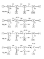
- Fig. 2 to 4 explain how the measurement will be executed.
- the doted path in each figure indicates the path which is currently under investigation. All three exemplary data paths BC-D1, BC-D2, BC-D3 from the source device BC to the sink devices D1, D2, 3 will be examined.
- Fig. 2 shows a schematic design with a bus controller and a bus network without electrical deteriorations.
- the bus network under test itself consist of
- the source device BC is connected via a stub SA1 to a coupler C1 connected to the main line ML.
- the couplers C1, C2, C3, C4 are connected via cables CA1, CA2, CA3, CA4.
- Fig. 2a shows the situation without measurement.
- Fig. 2b shows the situation where sink device D1 is tested. The tested path is indicated by the doted line.
- Fig. 2c and 2d show the situation where sink devices D2 and D3 are tested.
- This reference measurement has to be executed at the beginning of in service phase of the data bus network to determine a datum for a healthy bus topology.
- Fig. 3 shows how the process works in case of an increased attenuation (e.g. aging of contacts, deterioration of the dielectric etc.).
- the cable segment CA2 will have an higher attenuation level than all other segments CA1, CA3.
- the measurement is executed at t n , some time after the initial measurement t 0 .
- the process will loop through all data connections and measure the attenuation level until the transmission between the signal source of the bus controller and the device under test will break. And again the dotted path indicates the path on which the measurement will take place.
- the triangle TR indicates the position of the distortion .
- the comparison between the current run and the first run will show an increase of the attenuation for the transmission paths source device BC to sink device D2 and source device BC to sink device D3.
- a significant increase of the attenuation was detected.
- the threshold is set to absolute 0,5 dB. Therefore the detected absolute delta in the measurement path BC to D2 and BC to D3 is above the given threshold.
- the level of the increase is the same for both paths, so that the source of the additional attenuation must be located in the common elements for the path BC to D2 and BC to D3, but not common with path BC to D1.
- the common element is Cable CA2.
- the detection of stub errors will be processed in the same way ( fig. 4 ).
- the error will be located at the Stub SA3 (triangle TR) and the loops are marked with a doted line.
Landscapes
- Engineering & Computer Science (AREA)
- Computer Networks & Wireless Communication (AREA)
- Signal Processing (AREA)
- Small-Scale Networks (AREA)
- Cable Transmission Systems, Equalization Of Radio And Reduction Of Echo (AREA)
Abstract
a source device (BC1,...,BCm) comprises a variable attenuator (VA) and a terminal unit (TU) applies a test signal to the at least one data path (BC1-D1, BC1-D2, BC1-D3, or BCm-Dn) of the bus network (BN) under test,
a sink device (D) comprises a terminal unit (TU),
the attenuation of the at least one data path (BC1-D1, BC1-D2, BC1-D3, ... BCm-Dn) between the source device (BC1,...,BCm) and the at least one sink device (D1,...,Dn) is measured and compared with an reference measurement of the attenuation of the same data path (BC1-D1, BC1-D2, BC1-D3, ... BCm-Dn) between the source device (BC1,...,BCm) and the same sink device (D1,...Dn),
if the absolute difference between the reference measurement and the measurement is above a given threshold the position of the electrical deteriorations within a bus network is derived by using the wiring structure of the bus network (BN),
whereby the reference measurement is performed in a first non-recurring step of the method under undisturbed conditions on the at least one data path (BC1-D1, BC1-D2, BC1-D3, ... BCm-Dn) between the source device (BC1,...,BCm) and the at least one sink device (D1,...Dn).
Description
- The invention relates to a Method for detecting electrical deteriorations in a bus network according to
claim 1. - The current approaches for the detection of failures or electrical deterioration in data bus networks is either:
- a) to de-install all connected bus users and (if necessary) load the bus with dummy load. Then execute the measurement with a signal source (e.g. Signal Generator or special measurement equipment) and a signal sink (e.g. Oscilloscope or special measurement equipment). Repeat this measurement for each data path which is under interest. After the measurement the bus users have to be re-installed and the necessary acceptance and test procedure for the exchange of equipment has to be performed.
The disadvantages are the de-installation, installation and re-testing of the bus users and system. This leads to additional amount of time for the maintenance crew and there is still the risk that the de-installation and installation itself will produce additional errors. - b) or to use the Time Domain Reflectometry (TDR). For the TDR measurement, an impulse is transmitted into the wiring and the echo (which is produced by distortions in the impedance) is measured. The time between impulse and the reception of the echo is used to identify the position of the distortion, the value and shape of the received signal are used to identify the source of the distortion (connectors, open-end, break, short, etc.).
- The disadvantages for this method is that the wiring has to be opened to connect the TDR equipment. And, this is the more important disadvantage, for transformer coupled busses (like MIL-STD-1553B, CAN, etc.) the transmission characteristics and the bandwidth limitation of the transformers significantly reduces the informational value of the TDR measurement. For MIL-STD-1553B topologies using multi stub couplers, the TDR is not able to resolve the source of the echoes (for a 2 or more stub coupler the TDR cannot distinguish whether the echo was sourced by the first, second or n-th stub).
- It is therefore an object of the present invention to provide a method to investigate the health status of bus network and the localisation of wiring failures or electrical bus deterioration, without removal of equipment.
- This object is using the method having the features of
claim 1, ie by a method for detecting electrical deteriorations in a bus network, whereby the bus network comprises at least one data path to at least one device, comprising the steps: - applying a test signal by a equipment acting as generator (source) comprising a variable attenuator and a signal source to the at least one data path of the bus network under test,
- measuring the attenuation of the at least one data path between the at least one source and the at least one sink device
- comparing the measured attenuation with an reference measurement of the attenuation of the same data path between the source and the same sink device,
- deriving the position of the electrical deteriorations within a bus network by using the wiring structure of the bus network if the absolute difference between the reference measurement and the measurement is not within a given threshold,
- performing the reference measurement in a first non-recurring step of the method under undisturbed conditions on the at least one data path between the source and the at least one sink device.
- The advantage achieved by the invention is that it the method can be executed during build in test routines without the removal of equipment. Further the method can be included into build in test routines in existing equipment attached to the bus.
- The new idea is to establish an indirect measurement of the attenuation of the data paths between the source device including the measurement unit and all other sink devices and to compare the results of the current measurement with the stored results of the past measurements. With the inclusion of the knowledge of the wiring structure, the parts of the wiring, showing signs of electrical characteristics deterioration, can be identified.
- In an embodiment of the invention the measurement of the attenuation of a data path between the source and a sink device is performed in a loop, whereby the attenuation of the variable attenuator is increased gradually until no valid communication with a sink device under test in the bus network is possible.
- The measured attenuator level identifies the margin which is left until no valid communication with a specific sink is possible. Advantageously the transmission protocol of the signal of the source device defines the signal level ranges for valid and invalid signals (e.g. as it is defined within MIL-STD-1553B).
- The following describes the invention and embodiments of the invention with reference to the embodiments shown in the figures and explained. In the drawings:
- Fig. 1
- A schematic design of a bus network connected to a source device performing the method according to the invention,
- Fig. 2
- a schematic design according to
fig. 1 with a source device and a bus network without electrical deteriorations, - Fig. 3
- a schematic design according to
fig. 1 with a source device and a bus network with an electrical deteriorations in a main line segment, - Fig. 4
- a schematic design according to
fig. 1 with a source device and a bus network with an electrical deteriorations in a distribution feeder from the main line segment to a device. -
Fig.1 shows a schematic design of a bus network connected to one or more source devices. Each source device BC1,...,BCm comprises a terminal unit TU and a variable attenuator VA and the source device BC1,...,BCm is capable to take over the role of a sink device D1,...,Dn by deactivating the variable attenuator VA The source device is connected to a bus network BN under test. And one or more sink devices D1,...,Dn. Each sink device D1,...,Dn comprises a terminal unit TU. - The terminal unit is part of an equipment which allows to communicate according to the specified technology via a bus network. Normally a terminal unit TU is able to transmit and receive messages/signals.
- As an example the bus network BN itself is connected to three source device BC1, BC2, BC3 (acting as source) and four sink devices D1, D2, D3, D4 (acting as sinks). The network is based on a single lane network.
- According to the invention the reference measurement, which is an initial measurement, is performed in a first non-recurring step of the method under undisturbed conditions on the at least one data path between the source device and the at least one sink device. This means in other word, the reference measurement describes the condition of the bus network for the point in time to assuming that there are no electrical deteriorations in the bus network.
-
Fig. 2 to 4 explain how the measurement will be executed. The doted path in each figure indicates the path which is currently under investigation. All three exemplary data paths BC-D1, BC-D2, BC-D3 from the source device BC to the sink devices D1, D2, 3 will be examined. -
Fig. 2 shows a schematic design with a bus controller and a bus network without electrical deteriorations. The bus network under test itself consist of - The back bone or main line segment ML which ends are terminated by a terminator T,
- Stubs SA2, SA3, SA4 which are the distribution feeders from the main line ML to the sink devices D1, D2, D3
- Coupler C2, C3, C4 between main line ML and stub SA2, SA3, SA4, which can be either direct coupled or transformer coupled.
- The source device BC is connected via a stub SA1 to a coupler C1 connected to the main line ML. The couplers C1, C2, C3, C4 are connected via cables CA1, CA2, CA3, CA4.
-
Fig. 2a shows the situation without measurement.Fig. 2b shows the situation where sink device D1 is tested. The tested path is indicated by the doted line.Fig. 2c and 2d show the situation where sink devices D2 and D3 are tested. - At the end the measurement three attenuator values (which are equivalent to the margin the bus network provides for each data path) have been determined. The following table shows exemplarily the determined values:
Measurement Results D1 D2 D3 Current Run t0 -13dB -13,3dB -13,8dB - This reference measurement has to be executed at the beginning of in service phase of the data bus network to determine a datum for a healthy bus topology.
-
Fig. 3 shows how the process works in case of an increased attenuation (e.g. aging of contacts, deterioration of the dielectric etc.). The cable segment CA2 will have an higher attenuation level than all other segments CA1, CA3. The measurement is executed at tn, some time after the initial measurement t0. - The process will loop through all data connections and measure the attenuation level until the transmission between the signal source of the bus controller and the device under test will break. And again the dotted path indicates the path on which the measurement will take place. The triangle TR indicates the position of the distortion .
- The loop cycles for D2 and D3 will be affected by the distortion which will be visible in the measurement result listed in the next table.
Measurement Results D1 D2 D3 First Run t0 -13dB -13,3dB -13,8dB Current Run tn -13,1dB -14,1dB -14,6dB Delta -0,1dB -0,8dB -0,8dB - The comparison between the current run and the first run will show an increase of the attenuation for the transmission paths source device BC to sink device D2 and source device BC to sink device D3. For both measurement paths BC to D2 and BC to D3 a significant increase of the attenuation was detected. Exemplary the threshold is set to absolute 0,5 dB. Therefore the detected absolute delta in the measurement path BC to D2 and BC to D3 is above the given threshold.
- The level of the increase is the same for both paths, so that the source of the additional attenuation must be located in the common elements for the path BC to D2 and BC to D3, but not common with path BC to D1. The common element is Cable CA2.The combination of the past and current measurement and the knowledge of the network structure will lead to identification of the location of the distortion.
- Similar to the detection of main line errors the detection of stub errors will be processed in the same way (
fig. 4 ). For the next example the error will be located at the Stub SA3 (triangle TR) and the loops are marked with a doted line. - The loop cycle for D2 will be affected by the distortion which will be visible in the measurement result listed in the next table.
Measurement Results D1 D2 D3 First Run t0 -13dB -13,3dB -13,8dB Current Run tn -13,1dB -14,1 dB -13,9dB Delta -0,1dB -0,8dB -0,1dB - As expected only the measurement covering the Stub SA3(erroneous stub) will have the higher attenuation and this was the measurement in the path source device BC to sink device D2. No other paths are affected.
Claims (2)
- Method for detecting electrical deteriorations in a bus network (BN), whereby the bus network (BN) comprises at least one data path (BC1-D1, BC1-D2, BC1-D3, ..., BCm-Dn) to at least one sink device (D1, ... Dn ), characterised in
that a source device (BC1,...,BCm) comprising a variable attenuator (VA) and a terminal unit (TU) applies a test signal to the at least one data path (BC1-D1, BC1-D2, BC1-D3, ..., BCm-Dn) of the bus network (BN) under test,
that the attenuation of the at least one data path (BC1-D1, BC1-D2, BC1-D3,...,BCm-Dn) between the source device (BC1,...,BCm) and the at least one sink device (D1,..., Dn) is measured and compared with an reference measurement of the attenuation of the same data path (BC1-D1, BC1-D2, BC1-D3, ..., BCm-Dn) between the source device (BC1,...,BCm) and the same sink device (D1,...,Dn),
that if the absolute difference between the reference measurement and the measurement is above a given threshold the position of the electrical deteriorations within a bus network (BN) is derived by using the wiring structure of the bus network,
whereby the reference measurement is performed in a first non-recurring step of the method under undisturbed conditions on the at least one data path (BC1-D1, BC1-D2, BC1-D3, ..., BCm-Dn) between the source device (BC1,...,BCm) and the at least one sink device (D1, ... Dn). - Method according to claim 1,
characterised in that
the measurement of the attenuation of one or more data pathes (BC1-D1, BC1-D2, BC1-D3, ..., BCm-Dn) between the source device (BC) and a sink device (D1,... Dn) is performed in a loop, whereby the attenuation of the variable attenuator is increased gradually until no valid communication with a device under test in the bus network (BN) is possible.
Priority Applications (2)
| Application Number | Priority Date | Filing Date | Title |
|---|---|---|---|
| ES12004030.8T ES2532929T3 (en) | 2012-05-24 | 2012-05-24 | Method to detect electrical damage in a bus network |
| EP12004030.8A EP2667543B1 (en) | 2012-05-24 | 2012-05-24 | Method for detecting electrical deteriorations in a bus network |
Applications Claiming Priority (1)
| Application Number | Priority Date | Filing Date | Title |
|---|---|---|---|
| EP12004030.8A EP2667543B1 (en) | 2012-05-24 | 2012-05-24 | Method for detecting electrical deteriorations in a bus network |
Publications (2)
| Publication Number | Publication Date |
|---|---|
| EP2667543A1 true EP2667543A1 (en) | 2013-11-27 |
| EP2667543B1 EP2667543B1 (en) | 2015-01-07 |
Family
ID=46466043
Family Applications (1)
| Application Number | Title | Priority Date | Filing Date |
|---|---|---|---|
| EP12004030.8A Active EP2667543B1 (en) | 2012-05-24 | 2012-05-24 | Method for detecting electrical deteriorations in a bus network |
Country Status (2)
| Country | Link |
|---|---|
| EP (1) | EP2667543B1 (en) |
| ES (1) | ES2532929T3 (en) |
Citations (2)
| Publication number | Priority date | Publication date | Assignee | Title |
|---|---|---|---|---|
| GB1157207A (en) * | 1966-07-07 | 1969-07-02 | Philips Electronic Associated | Attenuation Measuring Device |
| EP1150458A2 (en) * | 2000-04-27 | 2001-10-31 | Nokia Mobile Phones Ltd. | Apparatus, and associated method, for measuring radio operating characteristics of a radio device |
-
2012
- 2012-05-24 EP EP12004030.8A patent/EP2667543B1/en active Active
- 2012-05-24 ES ES12004030.8T patent/ES2532929T3/en active Active
Patent Citations (2)
| Publication number | Priority date | Publication date | Assignee | Title |
|---|---|---|---|---|
| GB1157207A (en) * | 1966-07-07 | 1969-07-02 | Philips Electronic Associated | Attenuation Measuring Device |
| EP1150458A2 (en) * | 2000-04-27 | 2001-10-31 | Nokia Mobile Phones Ltd. | Apparatus, and associated method, for measuring radio operating characteristics of a radio device |
Also Published As
| Publication number | Publication date |
|---|---|
| EP2667543B1 (en) | 2015-01-07 |
| ES2532929T3 (en) | 2015-04-06 |
Similar Documents
| Publication | Publication Date | Title |
|---|---|---|
| US6614236B1 (en) | Cable link integrity detector | |
| US20080043629A1 (en) | System and method for detecting and locating faults in electronic communication bus systems | |
| EP2550752B1 (en) | Estimating pair symmetry status for a communication line | |
| US20130093434A1 (en) | Signal processing apparatuses and methods for identifying cable connections between ports | |
| GB2468925A (en) | Coupling a signal to and/or from a twisted pair cable | |
| Stroganova et al. | How to test long Ethernet channels parameters | |
| US20130033270A1 (en) | Electromagnetic interference test sytem with self-checking function and self-checking method | |
| TWI912521B (en) | System and method for measuring path loss of a conductive radio frequency (rf) test signal path | |
| US8570049B2 (en) | Method and apparatus for measuring AC shield continuity for shielded twisted pair structured datacomm cable link | |
| US6259256B1 (en) | Cable testing apparatus | |
| CN116348773A (en) | Systems and methods for compensating for power loss due to mismatch of radio frequency (RF) signal probes in conductive signal testing | |
| US9008280B2 (en) | Method and testing system for testing an analogue front end | |
| CN109738850A (en) | A kind of electric energy measuring equipment calibrating installation based on the switching of multi-standard table | |
| CN100582795C (en) | A bus parameter calibration method and system | |
| EP2710744B1 (en) | Measurement method | |
| CN105207847A (en) | Ethernet test system | |
| EP2667543B1 (en) | Method for detecting electrical deteriorations in a bus network | |
| CN208028916U (en) | Cable Operation Monitoring System | |
| CN103108349A (en) | Far-end radiofrequency unit channel failure detection method and system | |
| TWI635293B (en) | Cable operation detection system | |
| JP2017015450A (en) | Noise-proof characteristic evaluation method of cable and pair cable selection method | |
| US20150268287A1 (en) | Cable Measuring Device and Method | |
| GB2503636A (en) | Non-contact coupling of a signal to and from a twisted pair cable | |
| CN217133293U (en) | Control cable line inspection test system | |
| CN102055551B (en) | Device for testing anti-interference capability index |
Legal Events
| Date | Code | Title | Description |
|---|---|---|---|
| PUAI | Public reference made under article 153(3) epc to a published international application that has entered the european phase |
Free format text: ORIGINAL CODE: 0009012 |
|
| 17P | Request for examination filed |
Effective date: 20130411 |
|
| AK | Designated contracting states |
Kind code of ref document: A1 Designated state(s): AL AT BE BG CH CY CZ DE DK EE ES FI FR GB GR HR HU IE IS IT LI LT LU LV MC MK MT NL NO PL PT RO RS SE SI SK SM TR |
|
| AX | Request for extension of the european patent |
Extension state: BA ME |
|
| RAP1 | Party data changed (applicant data changed or rights of an application transferred) |
Owner name: AIRBUS DEFENCE AND SPACE GMBH |
|
| GRAP | Despatch of communication of intention to grant a patent |
Free format text: ORIGINAL CODE: EPIDOSNIGR1 |
|
| GRAS | Grant fee paid |
Free format text: ORIGINAL CODE: EPIDOSNIGR3 |
|
| INTG | Intention to grant announced |
Effective date: 20140923 |
|
| GRAA | (expected) grant |
Free format text: ORIGINAL CODE: 0009210 |
|
| AK | Designated contracting states |
Kind code of ref document: B1 Designated state(s): AL AT BE BG CH CY CZ DE DK EE ES FI FR GB GR HR HU IE IS IT LI LT LU LV MC MK MT NL NO PL PT RO RS SE SI SK SM TR |
|
| REG | Reference to a national code |
Ref country code: GB Ref legal event code: FG4D |
|
| REG | Reference to a national code |
Ref country code: CH Ref legal event code: EP |
|
| REG | Reference to a national code |
Ref country code: IE Ref legal event code: FG4D |
|
| REG | Reference to a national code |
Ref country code: AT Ref legal event code: REF Ref document number: 706404 Country of ref document: AT Kind code of ref document: T Effective date: 20150215 |
|
| REG | Reference to a national code |
Ref country code: DE Ref legal event code: R096 Ref document number: 602012004696 Country of ref document: DE Effective date: 20150226 |
|
| REG | Reference to a national code |
Ref country code: ES Ref legal event code: FG2A Ref document number: 2532929 Country of ref document: ES Kind code of ref document: T3 Effective date: 20150406 |
|
| REG | Reference to a national code |
Ref country code: NL Ref legal event code: VDEP Effective date: 20150107 |
|
| REG | Reference to a national code |
Ref country code: FR Ref legal event code: PLFP Year of fee payment: 4 |
|
| REG | Reference to a national code |
Ref country code: AT Ref legal event code: MK05 Ref document number: 706404 Country of ref document: AT Kind code of ref document: T Effective date: 20150107 |
|
| REG | Reference to a national code |
Ref country code: LT Ref legal event code: MG4D |
|
| PG25 | Lapsed in a contracting state [announced via postgrant information from national office to epo] |
Ref country code: HR Free format text: LAPSE BECAUSE OF FAILURE TO SUBMIT A TRANSLATION OF THE DESCRIPTION OR TO PAY THE FEE WITHIN THE PRESCRIBED TIME-LIMIT Effective date: 20150107 Ref country code: NO Free format text: LAPSE BECAUSE OF FAILURE TO SUBMIT A TRANSLATION OF THE DESCRIPTION OR TO PAY THE FEE WITHIN THE PRESCRIBED TIME-LIMIT Effective date: 20150407 Ref country code: SE Free format text: LAPSE BECAUSE OF FAILURE TO SUBMIT A TRANSLATION OF THE DESCRIPTION OR TO PAY THE FEE WITHIN THE PRESCRIBED TIME-LIMIT Effective date: 20150107 Ref country code: BG Free format text: LAPSE BECAUSE OF FAILURE TO SUBMIT A TRANSLATION OF THE DESCRIPTION OR TO PAY THE FEE WITHIN THE PRESCRIBED TIME-LIMIT Effective date: 20150407 Ref country code: LT Free format text: LAPSE BECAUSE OF FAILURE TO SUBMIT A TRANSLATION OF THE DESCRIPTION OR TO PAY THE FEE WITHIN THE PRESCRIBED TIME-LIMIT Effective date: 20150107 Ref country code: FI Free format text: LAPSE BECAUSE OF FAILURE TO SUBMIT A TRANSLATION OF THE DESCRIPTION OR TO PAY THE FEE WITHIN THE PRESCRIBED TIME-LIMIT Effective date: 20150107 |
|
| PG25 | Lapsed in a contracting state [announced via postgrant information from national office to epo] |
Ref country code: LV Free format text: LAPSE BECAUSE OF FAILURE TO SUBMIT A TRANSLATION OF THE DESCRIPTION OR TO PAY THE FEE WITHIN THE PRESCRIBED TIME-LIMIT Effective date: 20150107 Ref country code: NL Free format text: LAPSE BECAUSE OF FAILURE TO SUBMIT A TRANSLATION OF THE DESCRIPTION OR TO PAY THE FEE WITHIN THE PRESCRIBED TIME-LIMIT Effective date: 20150107 Ref country code: RS Free format text: LAPSE BECAUSE OF FAILURE TO SUBMIT A TRANSLATION OF THE DESCRIPTION OR TO PAY THE FEE WITHIN THE PRESCRIBED TIME-LIMIT Effective date: 20150107 Ref country code: AT Free format text: LAPSE BECAUSE OF FAILURE TO SUBMIT A TRANSLATION OF THE DESCRIPTION OR TO PAY THE FEE WITHIN THE PRESCRIBED TIME-LIMIT Effective date: 20150107 Ref country code: PL Free format text: LAPSE BECAUSE OF FAILURE TO SUBMIT A TRANSLATION OF THE DESCRIPTION OR TO PAY THE FEE WITHIN THE PRESCRIBED TIME-LIMIT Effective date: 20150107 Ref country code: IS Free format text: LAPSE BECAUSE OF FAILURE TO SUBMIT A TRANSLATION OF THE DESCRIPTION OR TO PAY THE FEE WITHIN THE PRESCRIBED TIME-LIMIT Effective date: 20150507 Ref country code: GR Free format text: LAPSE BECAUSE OF FAILURE TO SUBMIT A TRANSLATION OF THE DESCRIPTION OR TO PAY THE FEE WITHIN THE PRESCRIBED TIME-LIMIT Effective date: 20150408 |
|
| REG | Reference to a national code |
Ref country code: DE Ref legal event code: R097 Ref document number: 602012004696 Country of ref document: DE |
|
| PG25 | Lapsed in a contracting state [announced via postgrant information from national office to epo] |
Ref country code: SK Free format text: LAPSE BECAUSE OF FAILURE TO SUBMIT A TRANSLATION OF THE DESCRIPTION OR TO PAY THE FEE WITHIN THE PRESCRIBED TIME-LIMIT Effective date: 20150107 Ref country code: RO Free format text: LAPSE BECAUSE OF FAILURE TO SUBMIT A TRANSLATION OF THE DESCRIPTION OR TO PAY THE FEE WITHIN THE PRESCRIBED TIME-LIMIT Effective date: 20150107 Ref country code: EE Free format text: LAPSE BECAUSE OF FAILURE TO SUBMIT A TRANSLATION OF THE DESCRIPTION OR TO PAY THE FEE WITHIN THE PRESCRIBED TIME-LIMIT Effective date: 20150107 Ref country code: CZ Free format text: LAPSE BECAUSE OF FAILURE TO SUBMIT A TRANSLATION OF THE DESCRIPTION OR TO PAY THE FEE WITHIN THE PRESCRIBED TIME-LIMIT Effective date: 20150107 Ref country code: DK Free format text: LAPSE BECAUSE OF FAILURE TO SUBMIT A TRANSLATION OF THE DESCRIPTION OR TO PAY THE FEE WITHIN THE PRESCRIBED TIME-LIMIT Effective date: 20150107 |
|
| PLBE | No opposition filed within time limit |
Free format text: ORIGINAL CODE: 0009261 |
|
| STAA | Information on the status of an ep patent application or granted ep patent |
Free format text: STATUS: NO OPPOSITION FILED WITHIN TIME LIMIT |
|
| 26N | No opposition filed |
Effective date: 20151008 |
|
| REG | Reference to a national code |
Ref country code: CH Ref legal event code: PL |
|
| PG25 | Lapsed in a contracting state [announced via postgrant information from national office to epo] |
Ref country code: MC Free format text: LAPSE BECAUSE OF FAILURE TO SUBMIT A TRANSLATION OF THE DESCRIPTION OR TO PAY THE FEE WITHIN THE PRESCRIBED TIME-LIMIT Effective date: 20150107 Ref country code: LU Free format text: LAPSE BECAUSE OF FAILURE TO SUBMIT A TRANSLATION OF THE DESCRIPTION OR TO PAY THE FEE WITHIN THE PRESCRIBED TIME-LIMIT Effective date: 20150524 Ref country code: LI Free format text: LAPSE BECAUSE OF NON-PAYMENT OF DUE FEES Effective date: 20150531 Ref country code: CH Free format text: LAPSE BECAUSE OF NON-PAYMENT OF DUE FEES Effective date: 20150531 |
|
| REG | Reference to a national code |
Ref country code: IE Ref legal event code: MM4A |
|
| PG25 | Lapsed in a contracting state [announced via postgrant information from national office to epo] |
Ref country code: SI Free format text: LAPSE BECAUSE OF FAILURE TO SUBMIT A TRANSLATION OF THE DESCRIPTION OR TO PAY THE FEE WITHIN THE PRESCRIBED TIME-LIMIT Effective date: 20150107 |
|
| PG25 | Lapsed in a contracting state [announced via postgrant information from national office to epo] |
Ref country code: IE Free format text: LAPSE BECAUSE OF NON-PAYMENT OF DUE FEES Effective date: 20150524 |
|
| REG | Reference to a national code |
Ref country code: FR Ref legal event code: PLFP Year of fee payment: 5 |
|
| PG25 | Lapsed in a contracting state [announced via postgrant information from national office to epo] |
Ref country code: BE Free format text: LAPSE BECAUSE OF FAILURE TO SUBMIT A TRANSLATION OF THE DESCRIPTION OR TO PAY THE FEE WITHIN THE PRESCRIBED TIME-LIMIT Effective date: 20150107 |
|
| PG25 | Lapsed in a contracting state [announced via postgrant information from national office to epo] |
Ref country code: MT Free format text: LAPSE BECAUSE OF FAILURE TO SUBMIT A TRANSLATION OF THE DESCRIPTION OR TO PAY THE FEE WITHIN THE PRESCRIBED TIME-LIMIT Effective date: 20150107 |
|
| REG | Reference to a national code |
Ref country code: FR Ref legal event code: PLFP Year of fee payment: 6 |
|
| PG25 | Lapsed in a contracting state [announced via postgrant information from national office to epo] |
Ref country code: HU Free format text: LAPSE BECAUSE OF FAILURE TO SUBMIT A TRANSLATION OF THE DESCRIPTION OR TO PAY THE FEE WITHIN THE PRESCRIBED TIME-LIMIT; INVALID AB INITIO Effective date: 20120524 Ref country code: SM Free format text: LAPSE BECAUSE OF FAILURE TO SUBMIT A TRANSLATION OF THE DESCRIPTION OR TO PAY THE FEE WITHIN THE PRESCRIBED TIME-LIMIT Effective date: 20150107 |
|
| PG25 | Lapsed in a contracting state [announced via postgrant information from national office to epo] |
Ref country code: CY Free format text: LAPSE BECAUSE OF FAILURE TO SUBMIT A TRANSLATION OF THE DESCRIPTION OR TO PAY THE FEE WITHIN THE PRESCRIBED TIME-LIMIT Effective date: 20150107 |
|
| PG25 | Lapsed in a contracting state [announced via postgrant information from national office to epo] |
Ref country code: TR Free format text: LAPSE BECAUSE OF FAILURE TO SUBMIT A TRANSLATION OF THE DESCRIPTION OR TO PAY THE FEE WITHIN THE PRESCRIBED TIME-LIMIT Effective date: 20150107 |
|
| REG | Reference to a national code |
Ref country code: FR Ref legal event code: PLFP Year of fee payment: 7 |
|
| PG25 | Lapsed in a contracting state [announced via postgrant information from national office to epo] |
Ref country code: MK Free format text: LAPSE BECAUSE OF FAILURE TO SUBMIT A TRANSLATION OF THE DESCRIPTION OR TO PAY THE FEE WITHIN THE PRESCRIBED TIME-LIMIT Effective date: 20150107 Ref country code: PT Free format text: LAPSE BECAUSE OF FAILURE TO SUBMIT A TRANSLATION OF THE DESCRIPTION OR TO PAY THE FEE WITHIN THE PRESCRIBED TIME-LIMIT Effective date: 20150107 |
|
| PG25 | Lapsed in a contracting state [announced via postgrant information from national office to epo] |
Ref country code: AL Free format text: LAPSE BECAUSE OF FAILURE TO SUBMIT A TRANSLATION OF THE DESCRIPTION OR TO PAY THE FEE WITHIN THE PRESCRIBED TIME-LIMIT Effective date: 20150107 |
|
| REG | Reference to a national code |
Ref country code: DE Ref legal event code: R079 Ref document number: 602012004696 Country of ref document: DE Free format text: PREVIOUS MAIN CLASS: H04L0012260000 Ipc: H04L0043000000 |
|
| PGFP | Annual fee paid to national office [announced via postgrant information from national office to epo] |
Ref country code: DE Payment date: 20250521 Year of fee payment: 14 |
|
| PGFP | Annual fee paid to national office [announced via postgrant information from national office to epo] |
Ref country code: ES Payment date: 20250627 Year of fee payment: 14 Ref country code: GB Payment date: 20250521 Year of fee payment: 14 |
|
| PGFP | Annual fee paid to national office [announced via postgrant information from national office to epo] |
Ref country code: IT Payment date: 20250527 Year of fee payment: 14 |
|
| PGFP | Annual fee paid to national office [announced via postgrant information from national office to epo] |
Ref country code: FR Payment date: 20250528 Year of fee payment: 14 |