EP2667498A2 - Remote load bypass system - Google Patents
Remote load bypass system Download PDFInfo
- Publication number
- EP2667498A2 EP2667498A2 EP20130168832 EP13168832A EP2667498A2 EP 2667498 A2 EP2667498 A2 EP 2667498A2 EP 20130168832 EP20130168832 EP 20130168832 EP 13168832 A EP13168832 A EP 13168832A EP 2667498 A2 EP2667498 A2 EP 2667498A2
- Authority
- EP
- European Patent Office
- Prior art keywords
- remote
- bypass
- current
- choke
- module
- Prior art date
- Legal status (The legal status is an assumption and is not a legal conclusion. Google has not performed a legal analysis and makes no representation as to the accuracy of the status listed.)
- Withdrawn
Links
- 241001672018 Cercomela melanura Species 0.000 claims abstract description 14
- 230000005540 biological transmission Effects 0.000 claims description 38
- 238000004804 winding Methods 0.000 claims description 12
- 230000004044 response Effects 0.000 claims description 8
- 238000001514 detection method Methods 0.000 claims description 6
- 230000008878 coupling Effects 0.000 claims description 5
- 238000010168 coupling process Methods 0.000 claims description 5
- 238000005859 coupling reaction Methods 0.000 claims description 5
- 238000012423 maintenance Methods 0.000 claims description 3
- 230000001960 triggered effect Effects 0.000 claims description 3
- 238000000034 method Methods 0.000 abstract description 9
- 238000010586 diagram Methods 0.000 description 3
- 230000006698 induction Effects 0.000 description 3
- 238000012986 modification Methods 0.000 description 3
- 230000004048 modification Effects 0.000 description 3
- 238000004146 energy storage Methods 0.000 description 2
- 230000035484 reaction time Effects 0.000 description 2
- 230000015556 catabolic process Effects 0.000 description 1
- 238000006073 displacement reaction Methods 0.000 description 1
- 238000005516 engineering process Methods 0.000 description 1
- 238000009434 installation Methods 0.000 description 1
- 230000007246 mechanism Effects 0.000 description 1
- 238000010248 power generation Methods 0.000 description 1
Images






Classifications
-
- H—ELECTRICITY
- H02—GENERATION; CONVERSION OR DISTRIBUTION OF ELECTRIC POWER
- H02M—APPARATUS FOR CONVERSION BETWEEN AC AND AC, BETWEEN AC AND DC, OR BETWEEN DC AND DC, AND FOR USE WITH MAINS OR SIMILAR POWER SUPPLY SYSTEMS; CONVERSION OF DC OR AC INPUT POWER INTO SURGE OUTPUT POWER; CONTROL OR REGULATION THEREOF
- H02M1/00—Details of apparatus for conversion
Definitions
- This subject matter of this disclosure relates generally to control systems, and more particularly to a control system and method of control that can be easily integrated with a modular stacked DC (MSDC) topology for sub-sea applications.
- MSDC modular stacked DC
- Modular stacked DC converter architectures are well suited for sub-sea applications requiring transmission and distribution over long distances. Unlike other DC transmission options, wherein the DC transmission (link) voltage is controlled, i.e. maintained nearly constant, the DC transmission (link) current is controlled in a modular stacked DC converter.
- the MSDC architecture gets its name from the fact that the architecture uses several DC-DC/AC-DC/DC-AC converter modules stacked and connected in series on the DC side, both at the sending end and at the receiving end of the transmission link.
- Subsea control systems may consist of dozens or hundreds of low power consumers, e.g. electrically driven sensors for the physical displacements of valves.
- Direct current cables are the most economic choice for long distance power transmission because DC power transmission and distribution can fundamentally overcome the cable capacitance and reactive power issue associated with AC power delivery.
- Direct current power transmission requires a subsea inverter, e.g. an inverter based on MSDC technology.
- An MSDC inverter in addition to converting DC to AC, may keep a subsea busbar voltage constant by way of boosting the voltage at the end of the transmission line.
- T/D subsea power transmission and distribution
- a load bypass switch 16 such as shown in Figure 1 may be required for each remote load and/or variable frequency drive (VFD) 18.
- VFD variable frequency drive
- Each load bypass switch 16 is connected in parallel to a respective remote load 18.
- the bypass switches 16 provide a bypass path to the transmission line current 14 in the event of open-circuit fault VFDs or loads 18 to ensure point-to-point power flow is maintained.
- Bypass switches 16 ensure that continuous point-to-point power flow is maintained. Known systems and methods generally provide switching operations at best within a few milliseconds. Fast operation of the bypass switches 16 is desirable to ensure reliable protection against open-circuit fault transients.
- the system and method of control should be applicable to any current source based DC T&D architecture.
- the system and method of control should, for example, be capable of being easily integrated with a modular stacked DC (MSDC) topology for sub-sea applications.
- MSDC modular stacked DC
- An exemplary embodiment of the disclosure is directed to a remote module bypass system.
- the exemplary embodiment further comprises a plurality of remote modules connected in series and receiving DC current in response to a DC transmission line current.
- a plurality of load bypass switches is configured such that each bypass switch is connected in parallel with a distinct and respective remote module selected from the plurality of remote modules and further such that each module is associated with a distinct and respective bypass switch.
- Each bypass switch provides a bypass path to a corresponding remote module DC current during an open-circuit load fault associated with the respective remote module.
- Each bypass switch comprises a coupled DC-choke and a thyristor over-voltage protection circuit integrated within and connected to the coupled DC-choke.
- Another embodiment is directed to a remote module bypass switch comprising a DC-choke coupling a DC source current to one or more remote modules.
- a thyristor over-voltage protection circuit is integrated within and connected to the coupled DC-choke such that the coupled DC-choke and thyristor over-voltage protection circuit form a bypass current path to a remote module subsequent to a remote module open circuit fault.
- bypass switch for open circuit faults described above is just one example of protection using a bypass switch due to one type of fault which is open-circuit.
- the bypass switch can also be used in case of other faults that prevent point-to-point power delivery to other series connected loads. For example - a trip of the motor circuit breaker, or a compressor fault.
- the bypass switch can also be activated from the control in order to intentionally bypass the loads. The intentional bypass can be due to several reasons such as tripping of a subsea inverter or any failure.
- Subsea cables or umbilicals are by far the most expensive components in long distance transmission systems.
- the embodiments described herein with reference to the Figures are directed to power transmission in the range of Megawatts to subsea loads and subsea energy storage in combination with long distance power transmission in a topology that alleviates the necessity for subsea cables with an excessively large cable cross-section to achieve a constant bus bar voltage when supplying high, short-time subsea control system power.
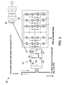
- FIG. 2 illustrates one portion of a DC power transmission/distribution system 20 that employs a load bypass switch 22 according to one embodiment.
- the load bypass switch 22 is a hybrid electronic/mechanical switch comprising an SCR 24 in combination with a normally open (NO) mechanical switch 26 and a normally closed (NC) mechanical switch 28.
- the SCR 24 advantageously comprises a switching reaction time in the microsecond range; while the mechanical switches 26, 28 comprise switching reaction times in the millisecond range greater than five milliseconds.
- SCR 24 is triggered instantaneously by a break over diode (BOD) 29 in the event of an open circuit fault on the remote VFD or load 18.
- BOD break over diode
- the normally closed switch 28 helps in black start operation, described in further detail herein.
- the electronic bypass switch 22 is realized by integrating a thyristor over-voltage protection circuit connected within a coupled DC choke 30, more clearly illustrated in Figure 3.
- Figure 3 is a simplified diagram illustrating connection of the bypass switch 22 within the coupled DC choke 30 of the VFD 18 depicted in Figure 2 .
- the resultant topology advantageously eliminates the requirement for additional passive components and ensures benign dv/dt and di/dt for the thyristor 24 during bypass operations.
- the coupled DC choke is preferable; however, a discrete dc choke can also be used.
- An open-circuit faulted VFD 18 or load may cause overvoltage across the thyristor 24.
- the bypass switch 22 functions as an over-voltage protection circuit that is implemented in a different way from a classical over-voltage protection circuit to turn-on the thyristor 24 and hence create a bypass path in just a few microseconds. Subsequent to turn-on of thyristor 24, the normally open mechanical switch 26, without any current braking capability, closes within a few milliseconds to create a more permanent bypass path for the transmission line current.
- FIG 4 illustrates the switching path 40 resulting during operation of the load bypass switch 22 depicted in Figures 2 and 3 .
- the voltage V_AK rises, and when V_AK > V_BOD, the BOD 29 triggers SCR 24 to provide a continuous path for the transmission line loop current in the event of flashover or any open circuit fault in the VFD or load 18.
- This switching path event is completed within a microseconds time period that is substantially less than one millisecond.
- the NO switch 26 is activated subsequent to the establishment of the bypass switching path 40 as stated herein to provide a more permanent continuous path for the transmission line loop current.
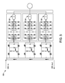
- FIG. 5 illustrates in more detail, a DC power transmission/distribution system 50 that employs a plurality of load bypass switches 22 according to one embodiment.
- T/D system 50 can be seen to employ a parallel connected output transformer 52-56 topology.
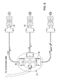
- FIG 6 illustrates a DC power transmission/distribution system 60 that employs an auxiliary power supply 62 integrated with the load bypass switch 22 also depicted in Figures 2 and 3 according to one embodiment.
- the auxiliary power supply 62 supports startup of the VFD/load 18 during a black start event.
- Black start of a system/load refers to a situation when startup of a load is required while auxiliary power is not available for the load.
- a small power, referred to as auxiliary power is required for a control system to start the load at a remote location connected to a power distribution grid.
- UPS uninterruptible power supply
- the auxiliary power supply 62 provides an inexpensive mechanism to provide auxiliary power to the VFDs or loads 18 in the absence of a UPS or other inexpensive means of supplying the necessary auxiliary power.
- the auxiliary power supply 62 comprises at least one additional winding 64 that is wound on a predetermined winding of the existing DC coupled choke 30.
- the auxiliary power supply 62 operates when a control scheme commands a very low frequency, small AC current to flow over the DC transmission current, causing induction at the remote location, as shown in Fig. 8 . This induction generates a small voltage for the auxiliary power supply.
- the NC breaker 28 provides the necessary circulation for the DC current.
- the coupled winding 64 acts like a very bad transformer, generating enough power to wake up the load or VFD 18.
- FIG. 7 illustrates a DC power transmission/distribution system 70 that employs a remote bypass-module-yard 72 interconnecting a plurality of load bypass switches 22 according to one embodiment.
- the T/D system 70 shown in Figure 7 illustrates bypassing a load set 74 from the remote bypass-module-yard 72.
- This embodiment advantageously provides a method to more easily locate faults in the system 70 and also enables continuous power flow to the remote loads upon failure of one or more power distribution cables located remotely in the MSDC system 70.
- Fig. 9 illustrates a bypass-module-yard and closing of one bypass switch 22 in the event one of the transmission cables is operationally damaged. Additional isolators are also shown which may be used to physically connect/isolate when current is not flowing in the cables. Such applications are typically used for maintenance. It should be noted that in the presence of remote bypass-module-yard 72, the NO switch 26 is redundant since with the help of bypass switches 22 in the bypass-module-yard 72, the faulty remote loads can be permanently bypassed as well.
- the bypass-module-yard 72 enables star configuration of loads as shown in Fig. 10 .
- the subsea system can stay operational even after serious faults, e. g. an anchor of a ship that completely destroys the distribution system.
- the bypass-module-yard 72 can always be of the same design (standardized and qualified once for subsea use); and it could have multiple ports (more than actually needed for the specific application) and one or two spare cables connected to these ports. In case of a fault with a subsea distribution cable, the affected MSDC module can be reconnected to one of these spare ports.
- control methods and system topologies employ a load bypass switch described herein for MSDC applications to enable continuous power flow to viable remote loads, even subsequent to failure of one or more remote loads inside the MSDC system.
- An inexpensive auxiliary power supply integrated with the load bypass switch enables black start of the MSDC system.
- a distribution cable layout associated with the load bypass switch enables power flow to the remote loads, even during failure of one or more power distribution cables that feed the remote loads located remotely in the MSDC system.
Landscapes
- Engineering & Computer Science (AREA)
- Power Engineering (AREA)
- Inverter Devices (AREA)
- Stand-By Power Supply Arrangements (AREA)
- Emergency Protection Circuit Devices (AREA)
Abstract
A load bypass switch (22) enables continuous power to remote loads in the event of 1) failure of one or more remote loads, or 2) faults within the remote loads, within a dc power system. The bypass switch utilizes the passive components of the dc loads or inverters and therefore reduces overall component count. A black start method for the remote dc system uses the same passives present inside the loads/inverters and simultaneously uses some of the features of the bypass switch. A bypass-module-yard (72) uses multiple bypass switches (22) enabling continuous power to the remote loads in the event of failure of one or more power distribution cables (in-feed to the remote loads) located remotely in the dc system.
Description
- This subject matter of this disclosure relates generally to control systems, and more particularly to a control system and method of control that can be easily integrated with a modular stacked DC (MSDC) topology for sub-sea applications.
- Modular stacked DC converter architectures are well suited for sub-sea applications requiring transmission and distribution over long distances. Unlike other DC transmission options, wherein the DC transmission (link) voltage is controlled, i.e. maintained nearly constant, the DC transmission (link) current is controlled in a modular stacked DC converter. The MSDC architecture gets its name from the fact that the architecture uses several DC-DC/AC-DC/DC-AC converter modules stacked and connected in series on the DC side, both at the sending end and at the receiving end of the transmission link.
- All subsea installations require control systems. Subsea control systems may consist of dozens or hundreds of low power consumers, e.g. electrically driven sensors for the physical displacements of valves. Direct current cables are the most economic choice for long distance power transmission because DC power transmission and distribution can fundamentally overcome the cable capacitance and reactive power issue associated with AC power delivery.
- Direct current power transmission requires a subsea inverter, e.g. an inverter based on MSDC technology. An MSDC inverter, in addition to converting DC to AC, may keep a subsea busbar voltage constant by way of boosting the voltage at the end of the transmission line.
- The loads at the remote subsea location of a subsea power transmission and distribution (T/D)
system 10 that employs a MSDC architecture are connected inseries 11 on thedistribution side 12, such as illustrated inFigure 1 . Such a topology is valid not only for a MSDC system, but for any system where thetransmission line current 14 is controlled to be stiff, such as, for example, a classic line commutated HVDC system. - A
load bypass switch 16, such as shown inFigure 1 may be required for each remote load and/or variable frequency drive (VFD) 18. Eachload bypass switch 16 is connected in parallel to a respectiveremote load 18. Thebypass switches 16 provide a bypass path to thetransmission line current 14 in the event of open-circuit fault VFDs orloads 18 to ensure point-to-point power flow is maintained. -
Bypass switches 16 ensure that continuous point-to-point power flow is maintained. Known systems and methods generally provide switching operations at best within a few milliseconds. Fast operation of thebypass switches 16 is desirable to ensure reliable protection against open-circuit fault transients. - In view of the foregoing, there is a need to provide a control system and method of control that can bypass a transmission current within a few microseconds. The system and method of control should be applicable to any current source based DC T&D architecture. The system and method of control should, for example, be capable of being easily integrated with a modular stacked DC (MSDC) topology for sub-sea applications.
- An exemplary embodiment of the disclosure is directed to a remote module bypass system. The exemplary embodiment further comprises a plurality of remote modules connected in series and receiving DC current in response to a DC transmission line current. A plurality of load bypass switches is configured such that each bypass switch is connected in parallel with a distinct and respective remote module selected from the plurality of remote modules and further such that each module is associated with a distinct and respective bypass switch. Each bypass switch provides a bypass path to a corresponding remote module DC current during an open-circuit load fault associated with the respective remote module. Each bypass switch comprises a coupled DC-choke and a thyristor over-voltage protection circuit integrated within and connected to the coupled DC-choke.
- Another embodiment is directed to a remote module bypass switch comprising a DC-choke coupling a DC source current to one or more remote modules. A thyristor over-voltage protection circuit is integrated within and connected to the coupled DC-choke such that the coupled DC-choke and thyristor over-voltage protection circuit form a bypass current path to a remote module subsequent to a remote module open circuit fault.
- Operation of the bypass switch for open circuit faults described above is just one example of protection using a bypass switch due to one type of fault which is open-circuit. However, the bypass switch can also be used in case of other faults that prevent point-to-point power delivery to other series connected loads. For example - a trip of the motor circuit breaker, or a compressor fault. In addition to fault handling, the bypass switch can also be activated from the control in order to intentionally bypass the loads. The intentional bypass can be due to several reasons such as tripping of a subsea inverter or any failure.
- The foregoing and other features, aspects and advantages of the invention are apparent from the following detailed description taken in conjunction with the accompanying drawings in which like characters represent like parts throughout the drawings, wherein:
-
Figure 1 is a simplified diagram illustrating a known sub-sea power transmission/distribution system with load bypass switches on the sub-sea side of the system; -
Figure 2 illustrates one portion of a DC power transmission/distribution system that employs a load bypass switch according to one embodiment; -
Figure 3 is a simplified diagram illustrating connection of the bypass switch within the coupled DC choke depicted inFigure 2 ; -
Figure 4 illustrates the switching path resulting during operation of the load bypass switch depicted inFigures 2 and3 ; -
Figure 5 illustrates in more detail, a DC power transmission/distribution system that employs a plurality of load bypass switches according to one embodiment; -
Figure 6 illustrates a DC power transmission/distribution system that employs a power supply integrated with the load bypass switch depicted inFigures 2 and3 according to one embodiment; -
Figure 7 illustrates a DC power transmission/distribution system that employs a bypass module yard interconnecting a plurality of load bypass switches according to one embodiment; -
Figure 8 illustrates a very low frequency, small AC current generated by the sending end stacked converter station (located on power generation side), to flow through the dc transmission cable over the DC transmission current, causing induction at the remote location e.g. inside the subsea inverter or bypass switch module to generate a power supply, according to one embodiment; -
Figure 9 illustrates a bypass-module-yard and closing of one bypass switch in the event of damage to a DC transmission cable, according to one embodiment; and -
Figure 10 illustrates a bypass-module-yard topology supporting a star configuration of loads, according to one embodiment. - While the above-identified drawing figures set forth alternative embodiments, other embodiments of the present invention are also contemplated, as noted in the discussion. In all cases, this disclosure presents illustrated embodiments of the present invention by way of representation and not limitation. Numerous other modifications and embodiments can be devised by those skilled in the art which fall within the scope of the principles of this invention.
- Subsea cables or umbilicals are by far the most expensive components in long distance transmission systems. The embodiments described herein with reference to the Figures are directed to power transmission in the range of Megawatts to subsea loads and subsea energy storage in combination with long distance power transmission in a topology that alleviates the necessity for subsea cables with an excessively large cable cross-section to achieve a constant bus bar voltage when supplying high, short-time subsea control system power.
-
Figure 2 illustrates one portion of a DC power transmission/distribution system 20 that employs aload bypass switch 22 according to one embodiment. Theload bypass switch 22 is a hybrid electronic/mechanical switch comprising anSCR 24 in combination with a normally open (NO)mechanical switch 26 and a normally closed (NC)mechanical switch 28. TheSCR 24 advantageously comprises a switching reaction time in the microsecond range; while themechanical switches - During operation of the DC power T/
D system 20,SCR 24 is triggered instantaneously by a break over diode (BOD) 29 in the event of an open circuit fault on the remote VFD orload 18. The normally closedswitch 28 helps in black start operation, described in further detail herein. - The
electronic bypass switch 22 is realized by integrating a thyristor over-voltage protection circuit connected within a coupledDC choke 30, more clearly illustrated inFigure 3. Figure 3 is a simplified diagram illustrating connection of thebypass switch 22 within the coupledDC choke 30 of theVFD 18 depicted inFigure 2 . The resultant topology advantageously eliminates the requirement for additional passive components and ensures benign dv/dt and di/dt for thethyristor 24 during bypass operations. The coupled DC choke is preferable; however, a discrete dc choke can also be used. - An open-circuit faulted
VFD 18 or load may cause overvoltage across thethyristor 24. Thebypass switch 22 functions as an over-voltage protection circuit that is implemented in a different way from a classical over-voltage protection circuit to turn-on thethyristor 24 and hence create a bypass path in just a few microseconds. Subsequent to turn-on ofthyristor 24, the normally openmechanical switch 26, without any current braking capability, closes within a few milliseconds to create a more permanent bypass path for the transmission line current. -
Figure 4 illustrates theswitching path 40 resulting during operation of theload bypass switch 22 depicted inFigures 2 and3 . The voltage V_AK rises, and when V_AK > V_BOD, theBOD 29 triggers SCR 24 to provide a continuous path for the transmission line loop current in the event of flashover or any open circuit fault in the VFD orload 18. This switching path event is completed within a microseconds time period that is substantially less than one millisecond. TheNO switch 26 is activated subsequent to the establishment of thebypass switching path 40 as stated herein to provide a more permanent continuous path for the transmission line loop current. -
Figure 5 illustrates in more detail, a DC power transmission/distribution system 50 that employs a plurality of load bypass switches 22 according to one embodiment. T/D system 50 can be seen to employ a parallel connected output transformer 52-56 topology. -
Figure 6 illustrates a DC power transmission/distribution system 60 that employs anauxiliary power supply 62 integrated with theload bypass switch 22 also depicted inFigures 2 and3 according to one embodiment. Theauxiliary power supply 62 supports startup of the VFD/load 18 during a black start event. - Black start of a system/load refers to a situation when startup of a load is required while auxiliary power is not available for the load. A small power, referred to as auxiliary power is required for a control system to start the load at a remote location connected to a power distribution grid.
- An uninterruptible power supply (UPS) for energy storage is typically available which provides sufficient auxiliary power for control and accessories to start a remote load connected to a power grid. Some applications where accessing the remote load is very expensive, such as subsea applications where the loads are located up to 3000 meters deep and more than 100 miles away from the shore, may not be serviceable by a UPS due to UPS breakdowns or complete discharge of the UPS.
- With continued reference to
Figure 6 , theauxiliary power supply 62 provides an inexpensive mechanism to provide auxiliary power to the VFDs or loads 18 in the absence of a UPS or other inexpensive means of supplying the necessary auxiliary power. Theauxiliary power supply 62 comprises at least one additional winding 64 that is wound on a predetermined winding of the existing DC coupledchoke 30. Theauxiliary power supply 62 operates when a control scheme commands a very low frequency, small AC current to flow over the DC transmission current, causing induction at the remote location, as shown inFig. 8 . This induction generates a small voltage for the auxiliary power supply. During a black start event, theNC breaker 28 provides the necessary circulation for the DC current. The coupled winding 64 acts like a very bad transformer, generating enough power to wake up the load orVFD 18. - In summary explanation, sending low frequency AC current (small amplitude) over DC transmission current (large amplitude) using a DC transmission cable as a medium, and using this low frequency AC current component (very low frequency as compared to 60Hz and therefore requiring low reactive power from the sending end during black start) to generate small control voltage by using an existing DC choke of the subsea inverter is a novel technique for supporting startup of the VFD/
load 18 during a black start event. -
Figure 7 illustrates a DC power transmission/distribution system 70 that employs a remote bypass-module-yard 72 interconnecting a plurality of load bypass switches 22 according to one embodiment. The T/D system 70 shown inFigure 7 illustrates bypassing a load set 74 from the remote bypass-module-yard 72. This embodiment advantageously provides a method to more easily locate faults in thesystem 70 and also enables continuous power flow to the remote loads upon failure of one or more power distribution cables located remotely in theMSDC system 70. -
Fig. 9 illustrates a bypass-module-yard and closing of onebypass switch 22 in the event one of the transmission cables is operationally damaged. Additional isolators are also shown which may be used to physically connect/isolate when current is not flowing in the cables. Such applications are typically used for maintenance. It should be noted that in the presence of remote bypass-module-yard 72, theNO switch 26 is redundant since with the help of bypass switches 22 in the bypass-module-yard 72, the faulty remote loads can be permanently bypassed as well. - The bypass-module-
yard 72 enables star configuration of loads as shown inFig. 10 . The subsea system can stay operational even after serious faults, e. g. an anchor of a ship that completely destroys the distribution system. The bypass-module-yard 72 can always be of the same design (standardized and qualified once for subsea use); and it could have multiple ports (more than actually needed for the specific application) and one or two spare cables connected to these ports. In case of a fault with a subsea distribution cable, the affected MSDC module can be reconnected to one of these spare ports. - In further summary explanation, control methods and system topologies employ a load bypass switch described herein for MSDC applications to enable continuous power flow to viable remote loads, even subsequent to failure of one or more remote loads inside the MSDC system. An inexpensive auxiliary power supply integrated with the load bypass switch enables black start of the MSDC system. A distribution cable layout associated with the load bypass switch enables power flow to the remote loads, even during failure of one or more power distribution cables that feed the remote loads located remotely in the MSDC system. It will be appreciated by those skilled in the relevant art that MSDC is one of many examples of a current-link based DC T/D systems. The principles described herein are applicable to any system where loads are connected in series being supplied through a current source and hence requiring bypassing of loads in the event of faults/intentional load disengagement.
- While only certain features of the invention have been illustrated and described herein, many modifications and changes will occur to those skilled in the art. It is, therefore, to be understood that the appended claims are intended to cover all such modifications and changes as fall within the scope of the invention.
- Various aspects and embodiments of the present invention are defined by the following numbered clauses:
- 1. A remote load bypass system comprising:
- a plurality of remote subsea inverter modules connected in series and receiving DC current in response to a DC transmission line current;
- a plurality of load bypass switches, wherein each bypass switch is connected in parallel with a remote module selected from the plurality of remote modules such that each module is associated with a distinct and respective bypass switch, and further wherein each bypass switch provides a bypass path to a corresponding remote module DC current during a fault or intentional bypass associated with the respective remote module, and further wherein each bypass switch comprises:
- a coupled DC-choke or at least one discrete subsea inverter DC-choke; and
- an over-voltage detection/protection circuit integrated within the coupled DC-choke or at least one discrete subsea inverter DC-choke.
- 2. The remote load bypass system according to clause 1, further comprising a modular stacked DC current source configured to generate the DC current.
- 3. The remote load bypass system according to any preceding clause, wherein the plurality of remote modules are configured via a modular stacked DC topology.
- 4. The remote load bypass system according to any preceding clause, further comprising a high voltage DC current source configured to generate the DC current.
- 5. The remote load bypass system according to any preceding clause, wherein each bypass switch further comprises a break over diode configured to trigger a respective thyristor subsequent to an open circuit fault for a corresponding remote module.
- 6. The remote load bypass system according to any preceding clause, wherein the bypass switch triggers the respective thyristor within microseconds and substantially less than one millisecond of the open circuit fault.
- 7. The remote load bypass system according to any preceding clause, wherein each bypass switch further comprises a normally open (NO) mechanical switch configured to close subsequent to triggering of the respective thyristor.
- 8. The remote load bypass system according to any preceding clause, wherein the bypass switch closes the NO mechanical switch within milliseconds and subsequent to triggering of the respective thyristor.
- 9. The remote load bypass system according to any preceding clause, wherein each bypass switch further comprises a normally closed (NC) mechanical switch configured to provide circulation of DC current to a respective remote module during a black start event.
- 10. The remote load bypass system according to any preceding clause, further comprising an auxiliary winding coupled to a predetermined winding of the coupled DC choke or at least one discrete choke, wherein the auxiliary winding generates and supplies an AC current to the respective remote module in response to the circulated DC current during the black start event.
- 11. The remote load bypass system according to any preceding clause, wherein the AC current is generated at a frequency substantially less than 60 Hz and flows over the circulated DC current.
- 12. The remote load bypass system according to any preceding clause, further comprising a remote cable bypass-module-yard configured to bypass a predetermined set of remote modules isolated from the remaining remote modules by a distribution cable fault or in preparation for maintenance of selected remote modules.
- 13. The remote load bypass system according to any preceding clause, wherein at least one remote module comprises a variable frequency drive.
- 14. A remote load bypass switch comprising:
- at least one of a DC-choke coupling a DC source current to one or more remote subsea inverter modules or at least one remote subsea inverter module discrete DC-choke coupling the DC current source to one or more remote subsea inverter modules; and
- a thyristor or over-voltage detection/protection circuit integrated within and connected to the coupled DC-choke or at least one inverter discrete DC-choke, wherein the coupled DC-choke or at least one inverter discrete DC-choke and thyristor or over-voltage detection/protection circuit together are configured to provide a bypass current path to a remote module subsequent to a remote module fault or in response to an intentional bypass command.
- 15. The remote load bypass switch according to any preceding clause, wherein at least one remote module comprises a remote load or variable frequency drive.
- 16. The remote load bypass switch according to any preceding clause, further comprising a break over diode configured to trigger a thyristor subsequent to an open circuit fault for a corresponding remote module such that the triggered thyristor forms one portion of the bypass current path.
- 17. The remote load bypass switch according to any preceding clause, wherein the bypass current path is formed within microseconds and substantially less than one millisecond of the open circuit fault.
- 18. The remote load bypass switch according to any preceding clause, further comprising a normally open (NO) mechanical switch coupled to the thyristor by the coupled DC-choke or inverter discrete choke and providing a circulation path of DC current to the remote module subsequent to triggering of the thyristor.
- 19. The remote load bypass switch according to any preceding clause, wherein the NO mechanical switch closes within milliseconds and subsequent to triggering of the thyristor.
- 20. The remote load bypass switch according to any preceding clause, further comprising a normally closed (NC) mechanical switch coupled to the thyristor by the coupled DC-choke or inverter discrete DC-choke and providing a circulation path of DC current to one or more remote modules during a black start event.
- 21. The remote load bypass switch according to any preceding clause, further comprising an auxiliary winding coupled to a predetermined winding of the coupled DC-choke or inverter discrete DC-choke, wherein the auxiliary winding generates and supplies an AC current to at least one remote module in response to circulated DC current via the NC mechanical switch during the black start event.
- 22. The remote load bypass switch according to any preceding clause, wherein the AC current is generated at a frequency substantially less than 60 Hz and flows over the circulated DC current.
- 23. The remote load bypass switch according to any preceding clause, further comprising a remote cable bypass-module-yard providing a bypass path to a predetermined subset of remote modules isolated from a set of remote modules when the remote load bypass switch provides a bypass current path to a plurality of remote modules subsequent to a remote module open circuit fault or a load fault.
- 24. The remote load bypass switch according to any preceding clause, wherein the set of remote modules are configured in a star topology.
- 25. The remote load bypass switch according to any preceding clause, wherein the subset of remote modules are configured in a star topology.
Claims (15)
- A remote load bypass system (20) comprising:a plurality of remote subsea inverter modules connected in series and receiving DC current in response to a DC transmission line current;
a plurality of load bypass switches (22), wherein each bypass switch is connected in parallel with a remote module selected from the plurality of remote modules such that each module is associated with a distinct and respective bypass switch, and further wherein each bypass switch provides a bypass path to a corresponding remote module DC current during a fault or intentional bypass associated with the respective remote module, and further wherein each bypass switch comprises:a coupled DC-choke (30) or at least one discrete subsea inverter DC-choke; andan over-voltage detection/protection circuit integrated within the coupled DC-choke (30) or at least one discrete subsea inverter DC-choke. - The remote load bypass system (20) according to claim 1, further comprising a modular stacked DC current source configured to generate the DC current.
- The remote load bypass system (20) according to either of claim 1 or 2, wherein the plurality of remote modules are configured via a modular stacked DC topology.
- The remote load bypass system (20) according to any of the preceding claims, further comprising a high voltage DC current source configured to generate the DC current.
- The remote load bypass system according to any of the preceding claims, wherein each bypass switch (22) further comprises a break over diode (29) configured to trigger a respective thyristor (24) subsequent to an open circuit fault for a corresponding remote module.
- The remote load bypass system according to claim 5, wherein the bypass switch (22) triggers the respective thyristor (24) within substantially less than one millisecond of the open circuit fault.
- The remote load bypass system according to claim 6, wherein each bypass switch (22) further comprises a normally open (NO) mechanical switch (26) configured to close subsequent to triggering of the respective thyristor (24).
- The remote load bypass system (20) according to any of the preceding claims, wherein each bypass switch (22) further comprises a normally closed (NC) mechanical switch (28) configured to provide circulation of DC current to a respective remote module during a black start event.
- The remote load bypass system according to claim 8, further comprising an auxiliary winding coupled to a predetermined winding (64) of the coupled DC choke (30) or at least one discrete choke, wherein the auxiliary winding generates and supplies an AC current to the respective remote module in response to the circulated DC current during the black start event.
- The remote load bypass system according to claim 9, wherein the AC current is generated at a frequency substantially less than 60 Hz and flows over the circulated DC current.
- The remote load bypass system (70) according to any of the preceding claims, further comprising a remote cable bypass-module-yard (72) configured to bypass a predetermined set of remote modules isolated from the remaining remote modules by a distribution cable fault or in preparation for maintenance of selected remote modules.
- The remote load bypass system according to any of the preceding claims, wherein at least one remote module comprises a variable frequency drive (18).
- A remote load bypass switch (22) comprising:at least one of a DC-choke (30) coupling a DC source current to one or more remote subsea inverter modules or at least one remote subsea inverter module discrete DC-choke coupling the DC current source to one or more remote subsea inverter modules; anda thyristor or over-voltage detection/protection circuit integrated within and connected to the coupled DC-choke (30) or at least one inverter discrete DC-choke, wherein the coupled DC-choke or at least one inverter discrete DC-choke and thyristor or over-voltage detection/protection circuit together are configured to provide a bypass current path to a remote module subsequent to a remote module fault or in response to an intentional bypass command.
- The remote load bypass switch according to claim 13, wherein at least one remote module comprises a remote load or variable frequency drive.
- The remote load bypass switch according to either of claim 13 or 14, further comprising a break over diode (29) configured to trigger a thyristor (24) subsequent to an open circuit fault for a corresponding remote module such that the triggered thyristor forms one portion of the bypass current path.
Applications Claiming Priority (1)
| Application Number | Priority Date | Filing Date | Title |
|---|---|---|---|
| US13/478,310 US20130313906A1 (en) | 2012-05-23 | 2012-05-23 | Remote load bypass system |
Publications (1)
| Publication Number | Publication Date |
|---|---|
| EP2667498A2 true EP2667498A2 (en) | 2013-11-27 |
Family
ID=48463847
Family Applications (1)
| Application Number | Title | Priority Date | Filing Date |
|---|---|---|---|
| EP20130168832 Withdrawn EP2667498A2 (en) | 2012-05-23 | 2013-05-23 | Remote load bypass system |
Country Status (5)
| Country | Link |
|---|---|
| US (1) | US20130313906A1 (en) |
| EP (1) | EP2667498A2 (en) |
| CN (1) | CN103427613A (en) |
| AU (1) | AU2013205925A1 (en) |
| SG (1) | SG195500A1 (en) |
Cited By (6)
| Publication number | Priority date | Publication date | Assignee | Title |
|---|---|---|---|---|
| WO2015038691A1 (en) * | 2013-09-11 | 2015-03-19 | General Electric Company | Method and system for architecture, control, and protection systems of modular stacked direct current subsea power system |
| EP2919354A1 (en) * | 2014-03-14 | 2015-09-16 | Siemens Aktiengesellschaft | Power supply arrangement of a wind farm |
| WO2015148977A1 (en) * | 2014-03-27 | 2015-10-01 | General Electric Company | System and method for direct current power transmission |
| WO2016075009A1 (en) * | 2014-11-10 | 2016-05-19 | Vetco Gray Scandinavia As | A plant for feeding electric power to low voltage subsea loads |
| WO2016074737A1 (en) * | 2014-11-14 | 2016-05-19 | Abb Technology Ltd | Cascaded converter cell converter with two converters and nesting of their cells |
| US10097002B2 (en) | 2015-06-30 | 2018-10-09 | Abb Schweiz Ag | Power transmission arrangement and method for operating a power transmission arrangement |
Families Citing this family (9)
| Publication number | Priority date | Publication date | Assignee | Title |
|---|---|---|---|---|
| CN104811073B (en) * | 2014-01-24 | 2019-05-31 | 通用电气能源电能变换科技有限公司 | Converter module, device, system and correlation technique |
| US9640982B2 (en) * | 2014-11-05 | 2017-05-02 | General Electric Company | Over-voltage protection system and method |
| US9812946B2 (en) * | 2016-02-03 | 2017-11-07 | Delta Electronics, Inc. | Power converter and operating method thereof |
| US10338126B2 (en) * | 2016-04-15 | 2019-07-02 | Infineon Technologies Ag | Open load detection in output stages |
| US10384548B2 (en) | 2016-04-28 | 2019-08-20 | Ge Global Sourcing Llc | Systems and methods for a vehicle inverter connection bus |
| JP6494673B2 (en) * | 2017-02-13 | 2019-04-03 | 三菱電機株式会社 | Integrated circuit device for driving a load |
| US10461542B2 (en) * | 2017-07-10 | 2019-10-29 | Ge Aviation Systems Llc | Power distribution network |
| CN112583242B (en) * | 2019-09-29 | 2021-11-12 | 南京南瑞继保电气有限公司 | Redundant energy taking circuit of power module bypass switch and control method thereof |
| CN115241964A (en) * | 2021-04-23 | 2022-10-25 | 中电普瑞电力工程有限公司 | A power supply system of an offshore platform and its fault protection method |
Family Cites Families (5)
| Publication number | Priority date | Publication date | Assignee | Title |
|---|---|---|---|---|
| US7615893B2 (en) * | 2000-05-11 | 2009-11-10 | Cameron International Corporation | Electric control and supply system |
| US8692408B2 (en) * | 2008-12-03 | 2014-04-08 | General Electric Company | Modular stacked subsea power system architectures |
| KR101361865B1 (en) * | 2009-04-06 | 2014-02-12 | 에이비비 테크놀로지 아게 | Power flow control in a meshed hvdc power transmission network |
| US20110241433A1 (en) * | 2010-03-30 | 2011-10-06 | General Electric Company | Dc transmission system for remote solar farms |
| MX2012011719A (en) * | 2010-04-08 | 2013-03-20 | Framo Eng As | System and method for subsea power distribution network. |
-
2012
- 2012-05-23 US US13/478,310 patent/US20130313906A1/en not_active Abandoned
-
2013
- 2013-05-17 AU AU2013205925A patent/AU2013205925A1/en not_active Abandoned
- 2013-05-22 SG SG2013039789A patent/SG195500A1/en unknown
- 2013-05-23 CN CN2013101944171A patent/CN103427613A/en active Pending
- 2013-05-23 EP EP20130168832 patent/EP2667498A2/en not_active Withdrawn
Non-Patent Citations (1)
| Title |
|---|
| None |
Cited By (12)
| Publication number | Priority date | Publication date | Assignee | Title |
|---|---|---|---|---|
| WO2015038691A1 (en) * | 2013-09-11 | 2015-03-19 | General Electric Company | Method and system for architecture, control, and protection systems of modular stacked direct current subsea power system |
| US9178349B2 (en) | 2013-09-11 | 2015-11-03 | General Electric Company | Method and system for architecture, control, and protection systems of modular stacked direct current subsea power system |
| EP2919354A1 (en) * | 2014-03-14 | 2015-09-16 | Siemens Aktiengesellschaft | Power supply arrangement of a wind farm |
| CN104917290A (en) * | 2014-03-14 | 2015-09-16 | 西门子公司 | Power supply arrangement of a wind farm |
| US9590452B2 (en) | 2014-03-14 | 2017-03-07 | Siemens Aktiengesellschaft | Power supply arrangement of a wind farm |
| CN104917290B (en) * | 2014-03-14 | 2019-10-11 | 西门子公司 | Power supply for wind farms |
| WO2015148977A1 (en) * | 2014-03-27 | 2015-10-01 | General Electric Company | System and method for direct current power transmission |
| US20170126008A1 (en) * | 2014-03-27 | 2017-05-04 | General Electric Company | System and method for direct current power transmission |
| US10916947B2 (en) | 2014-03-27 | 2021-02-09 | Ge Oil & Gas Uk Ltd | System and method for direct current power transmission |
| WO2016075009A1 (en) * | 2014-11-10 | 2016-05-19 | Vetco Gray Scandinavia As | A plant for feeding electric power to low voltage subsea loads |
| WO2016074737A1 (en) * | 2014-11-14 | 2016-05-19 | Abb Technology Ltd | Cascaded converter cell converter with two converters and nesting of their cells |
| US10097002B2 (en) | 2015-06-30 | 2018-10-09 | Abb Schweiz Ag | Power transmission arrangement and method for operating a power transmission arrangement |
Also Published As
| Publication number | Publication date |
|---|---|
| AU2013205925A1 (en) | 2013-12-12 |
| SG195500A1 (en) | 2013-12-30 |
| CN103427613A (en) | 2013-12-04 |
| US20130313906A1 (en) | 2013-11-28 |
Similar Documents
| Publication | Publication Date | Title |
|---|---|---|
| EP2667498A2 (en) | Remote load bypass system | |
| CN100380767C (en) | Wind energy system and method for operating such a wind energy system | |
| RU2592066C2 (en) | Dc power supply system with possibility of system protection | |
| CN102239618B (en) | Systems and methods for electrical device protection | |
| US10523132B2 (en) | Start-up of HVDC converters | |
| US20170373498A1 (en) | Distribution of electric energy on a vessel | |
| KR20200003809A (en) | Electric Charging System And Method | |
| US20170126008A1 (en) | System and method for direct current power transmission | |
| US10615587B2 (en) | Bipolar DC power transmission scheme | |
| WO2021017654A1 (en) | Fault isolation apparatus, direct current boosting apparatus and inversion apparatus | |
| CN102013866A (en) | Static exciter of an electric generator, method for retrofitting and method for operating the same | |
| KR101175576B1 (en) | Static energising system for a generator and method for operation of such an energising system | |
| KR102290404B1 (en) | power distribution system | |
| CN110192343B (en) | Power supply system and method | |
| US11146100B2 (en) | Power supply system and method | |
| NL2006296C2 (en) | Device to protect an electric power distribution network against current faults. | |
| CN109565275B (en) | Power distribution system and method | |
| CN102804592A (en) | Emergency adjusting device for blade adjusting systems of wind power plants | |
| JPWO2020121466A1 (en) | Power supply system and power supply method | |
| ES2327487B1 (en) | ASYNCHRON SYSTEM AND METHOD OF OPERATION APPLICABLE TO A DOUBLE-POWERED TYPE AIRCRAFTER (DFIG). | |
| Sangeetha et al. | Improved Control of Offshore Wind Farms Using Partially Selective DC Fault Protection on the MTDC Network | |
| HK40006926A (en) | Installation for powering auxiliary equipment in electrical energy generation plants |
Legal Events
| Date | Code | Title | Description |
|---|---|---|---|
| PUAI | Public reference made under article 153(3) epc to a published international application that has entered the european phase |
Free format text: ORIGINAL CODE: 0009012 |
|
| AK | Designated contracting states |
Kind code of ref document: A2 Designated state(s): AL AT BE BG CH CY CZ DE DK EE ES FI FR GB GR HR HU IE IS IT LI LT LU LV MC MK MT NL NO PL PT RO RS SE SI SK SM TR |
|
| AX | Request for extension of the european patent |
Extension state: BA ME |
|
| STAA | Information on the status of an ep patent application or granted ep patent |
Free format text: STATUS: THE APPLICATION IS DEEMED TO BE WITHDRAWN |
|
| 18D | Application deemed to be withdrawn |
Effective date: 20161201 |