EP2667482B1 - Motor rotor, molded motor, air conditioner, and method for producing molded motor - Google Patents
Motor rotor, molded motor, air conditioner, and method for producing molded motor Download PDFInfo
- Publication number
- EP2667482B1 EP2667482B1 EP12736286.1A EP12736286A EP2667482B1 EP 2667482 B1 EP2667482 B1 EP 2667482B1 EP 12736286 A EP12736286 A EP 12736286A EP 2667482 B1 EP2667482 B1 EP 2667482B1
- Authority
- EP
- European Patent Office
- Prior art keywords
- rotor
- resin
- magnet
- section
- bracket
- Prior art date
- Legal status (The legal status is an assumption and is not a legal conclusion. Google has not performed a legal analysis and makes no representation as to the accuracy of the status listed.)
- Revoked
Links
Images


Classifications
-
- H—ELECTRICITY
- H02—GENERATION; CONVERSION OR DISTRIBUTION OF ELECTRIC POWER
- H02K—DYNAMO-ELECTRIC MACHINES
- H02K1/00—Details of the magnetic circuit
- H02K1/06—Details of the magnetic circuit characterised by the shape, form or construction
- H02K1/22—Rotating parts of the magnetic circuit
- H02K1/27—Rotor cores with permanent magnets
- H02K1/2706—Inner rotors
- H02K1/272—Inner rotors the magnetisation axis of the magnets being perpendicular to the rotor axis
- H02K1/274—Inner rotors the magnetisation axis of the magnets being perpendicular to the rotor axis the rotor consisting of two or more circumferentially positioned magnets
- H02K1/2753—Inner rotors the magnetisation axis of the magnets being perpendicular to the rotor axis the rotor consisting of two or more circumferentially positioned magnets the rotor consisting of magnets or groups of magnets arranged with alternating polarity
- H02K1/278—Surface mounted magnets; Inset magnets
-
- H—ELECTRICITY
- H02—GENERATION; CONVERSION OR DISTRIBUTION OF ELECTRIC POWER
- H02K—DYNAMO-ELECTRIC MACHINES
- H02K1/00—Details of the magnetic circuit
- H02K1/04—Details of the magnetic circuit characterised by the material used for insulating the magnetic circuit or parts thereof
-
- H—ELECTRICITY
- H02—GENERATION; CONVERSION OR DISTRIBUTION OF ELECTRIC POWER
- H02K—DYNAMO-ELECTRIC MACHINES
- H02K1/00—Details of the magnetic circuit
- H02K1/06—Details of the magnetic circuit characterised by the shape, form or construction
- H02K1/22—Rotating parts of the magnetic circuit
- H02K1/27—Rotor cores with permanent magnets
- H02K1/2706—Inner rotors
- H02K1/272—Inner rotors the magnetisation axis of the magnets being perpendicular to the rotor axis
-
- H—ELECTRICITY
- H02—GENERATION; CONVERSION OR DISTRIBUTION OF ELECTRIC POWER
- H02K—DYNAMO-ELECTRIC MACHINES
- H02K1/00—Details of the magnetic circuit
- H02K1/06—Details of the magnetic circuit characterised by the shape, form or construction
- H02K1/22—Rotating parts of the magnetic circuit
- H02K1/28—Means for mounting or fastening rotating magnetic parts on to, or to, the rotor structures
- H02K1/30—Means for mounting or fastening rotating magnetic parts on to, or to, the rotor structures using intermediate parts, e.g. spiders
-
- H—ELECTRICITY
- H02—GENERATION; CONVERSION OR DISTRIBUTION OF ELECTRIC POWER
- H02K—DYNAMO-ELECTRIC MACHINES
- H02K11/00—Structural association of dynamo-electric machines with electric components or with devices for shielding, monitoring or protection
- H02K11/20—Structural association of dynamo-electric machines with electric components or with devices for shielding, monitoring or protection for measuring, monitoring, testing, protecting or switching
- H02K11/21—Devices for sensing speed or position, or actuated thereby
- H02K11/215—Magnetic effect devices, e.g. Hall-effect or magneto-resistive elements
-
- H—ELECTRICITY
- H02—GENERATION; CONVERSION OR DISTRIBUTION OF ELECTRIC POWER
- H02K—DYNAMO-ELECTRIC MACHINES
- H02K5/00—Casings; Enclosures; Supports
- H02K5/04—Casings or enclosures characterised by the shape, form or construction thereof
- H02K5/10—Casings or enclosures characterised by the shape, form or construction thereof with arrangements for protection from ingress, e.g. water or fingers
-
- H—ELECTRICITY
- H02—GENERATION; CONVERSION OR DISTRIBUTION OF ELECTRIC POWER
- H02K—DYNAMO-ELECTRIC MACHINES
- H02K5/00—Casings; Enclosures; Supports
- H02K5/04—Casings or enclosures characterised by the shape, form or construction thereof
- H02K5/16—Means for supporting bearings, e.g. insulating supports or means for fitting bearings in the bearing-shields
- H02K5/173—Means for supporting bearings, e.g. insulating supports or means for fitting bearings in the bearing-shields using bearings with rolling contact, e.g. ball bearings
- H02K5/1732—Means for supporting bearings, e.g. insulating supports or means for fitting bearings in the bearing-shields using bearings with rolling contact, e.g. ball bearings radially supporting the rotary shaft at both ends of the rotor
-
- H—ELECTRICITY
- H02—GENERATION; CONVERSION OR DISTRIBUTION OF ELECTRIC POWER
- H02K—DYNAMO-ELECTRIC MACHINES
- H02K15/00—Processes or apparatus specially adapted for manufacturing, assembling, maintaining or repairing of dynamo-electric machines
- H02K15/12—Impregnating, moulding insulation, heating or drying of windings, stators, rotors or machines
Definitions
- the present invention relates to a rotor of an electric motor assembled to a long or large-diameter shaft.
- the present invention relates to a mold motor in which the rotor of the electric motor is used.
- the present invention relates to an air conditioner in which the mold motor is mounted on a blower. Further, the present invention relates to a method of manufacturing the mold motor in which the rotor of the electric motor is used.
- a rotor is described of which exposure of a permanent magnet piece from an extraction hole is eliminated without degrading performance of a motor, relating to the rotor of a motor that comprises a rotor core in which electromagnetic steel plates are stacked; a permanent magnet piece of rare earth which is embedded in a plurality of embedding slots formed on the rotor core along its rotational direction; and a synthetic resin which is so integrally molded as to embed the rotor core and the permanent magnet piece, of which the extraction hole which is an extraction trace of a support pin for holding the rotor core at molding is formed at the synthetic resin part.
- One surface of the rotor core is provided with a presser member which presses the permanent magnet piece by closing the embedding slot, so that, at molding, the presser member abuts with the support pin for the rotor core to be held. After molding, the presser member is exposed from the extraction hole.
- a rotor of an electromotor which can accurately assemble the concentricity of a shaft and a rotator resin magnet outside diameter so that improvement of productivity and quality can be attained.
- the rotator of the electromotor relating to this invention in the rotor of the electromotor resin-forming a ring-shaped rotator magnet and a position detecting magnet integrally with the shaft, is characterized by providing a plurality of notches serving as positioning, when the magnets are resin formed, in an inside diameter of one end face of the ring-shaped rotor magnet.
- the present invention has been devised in view of the above and provides a rotor of an electric motor, a mold motor, an air conditioner, and a method of manufacturing the mold motor that, with regard to attaching the rotor to a shaft, enable the rotor to be easily attached to the shaft even if the shaft is long, enable the rotor to be attached to an arbitrary position of the shaft, and can be easily adapted to changes in specifications.
- Methods for attaching a rotor to a shaft are described in the documents DE 70 45 170 U and DE 10 2007 060 250 A1 .
- the present invention provides a rotor of an electric motor, a motor, an air conditioner, and a method of manufacturing the motor having resistance to highfrequency electrolytic corrosion.
- a rotor of an electric motor is configured in such a manner as to include: a rotor resin assembly; a shaft; and a bearing, wherein the rotor resin assembly includes: a rotor magnet including a substantially cylindrical yoke molded from thermoplastic resin containing a soft magnetic material or ferrite and a resin magnet integrally formed in the outer circumference of the yoke; a position detection magnet arranged at one end in an axial direction of the rotor magnet; and a rotor core arranged in an inner circumference of the rotor magnet and formed by laminating a predetermined number of electromagnetic steel plates, wherein the rotor magnet, the position detection magnet, and the rotor core are integrally formed by resin, and the shaft is inserted into the inner diameter section of the rotor core, and the rotor resin assembly is caulked by a jig to for a recess in the vicinity of inner diameter sections of both end faces of the rotor core and assembled
- a rotor of an electric motor is characterized in that the length (or the diameter) of a shaft and the position of the rotor in the shaft can be arbitrarily selected.
- the shaft is short and the position of the rotor in the shaft is predetermined. Therefore, it is possible to integrally mold a rotor magnet, a position detection magnet, the shaft, and the like using resin.
- the shaft is long, when integrally molding the rotor magnet, the position detection magnet, the shaft, and the like using resin, the length of the shaft is limited by the mold opening amount in resin molding and cannot be set to an arbitrary length.
- a short rotor core for attachment to the shaft is prepared.
- the rotor magnet, the position detection magnet, and the rotor core (arranged in the inner circumference of the rotor magnet) are integrally molded using thermoplastic resin. Thereafter, the rotor core is caulked and assembled to the shaft.
- the rotor is released from the limitations that, for example, the length of the shaft is limited by the mold opening amount at the time of resin molding and that, when the position of the rotor in the shaft changes, molds for respective positions are made necessary.
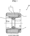
- a rotor resin assembly 100 obtained by integrally molding the rotor magnet, the position detection magnet, and the rotor core using thermoplastic resin and not yet attached to the shaft.
- FIG. 1 is a sectional view of the rotor resin assembly 100 according to the embodiment of the present invention.
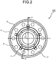
- FIG. 2 is a left side view of the rotor resin assembly 100.
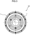
- FIG. 3 is a right side view of the rotor resin assembly 100.
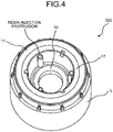
- FIG. 4 is a perspective view of the rotor resin assembly 100 viewed from a position detection magnet 11 side.
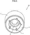
- FIG. 5 is a perspective view of the rotor resin assembly 100 viewed from the opposite side of the position detection magnet 11.
- the rotor resin assembly 100 shown in FIGS. 1 to 5 is obtained by integrally molding a rotor magnet 3 (obtained by injection-molding a resin magnet 5 on a yoke 4), the position detection magnet 11, and a rotor core 10 using thermoplastic resin (a resin section 17).
- the rotor core 10 and the rotor magnet 3 are inserted and assembled from an end face on a side including a gate (explained below) of the yoke 4.
- a gate (explained below) of the yoke 4.
- coaxiality of protrusions protrusions provided in the cored bar section of the lower mold
- cutouts 7 see FIG. 5
- a cylindrical section provided in the cored bar section of the lower mold and fit in the inner diameter section of the rotor core 10 is secured.
- the rotor core 10 is set in substantially the center of the rotor magnet 3 by the mold cored bar section. Consequently, the rotor core 10 is set in the position of the center of gravity of the rotor magnet 3 and thus a reduction in noise and a reduction in vibration of the electric motor can be attained.
- thermoplastic resin such as PBT (polybutylene terephthalate)
- PBT polybutylene terephthalate
- FIG. 6A is a side view of the yoke 4 viewed from recesses 6 side.
- FIG. 6B is a B-B sectional view of FIG. 6A.
- FIG. 6C is a side view of the yoke 4 viewed from the position detection magnet 11 side.
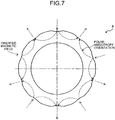
- FIG. 7 is a diagram of a state in which the yoke 4 is polar-anisotropically oriented by an oriented magnetic field on the outer side.
- FIG. 8 is an enlarged view of the yoke 4 shown in FIG. 6A .
- FIG. 9 is an enlarged view of the yoke 4 shown in FIG. 6C .
- FIG. 10 is a perspective view of the yoke 4 viewed from the pedestals 34.
- FIG. 10 is a perspective view of the yoke 4 viewed from the pedestals 34.
- FIG. 11 is a perspective view of the yoke 4 viewed from the recesses 6.
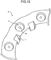
- FIG. 12 is a partially enlarged view of the yoke 4 shown in FIG. 11 .
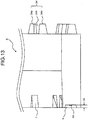
- FIG. 13 is a partially enlarged view of the yoke 4 shown in FIG. 6B .
- FIG. 14 is an enlarged view of the yoke 4 shown in FIG. 6B .
- the yoke 4 configuring the rotor magnet 3 is explained in detail with reference to FIGS. 6 to 14 .
- the yoke 4 provided on the inner side of the rotor magnet 3 is obtained by injection molding thermoplastic resin containing a soft magnetic material or ferrite.
- a strong magnet is arranged to provide an oriented magnetic field on the outer side of the section of the mold forming the outer circumference of the yoke 4. Consequently, the soft magnetic material or the ferrite contained in the yoke 4 is anisotropically oriented with respect to a polar direction.
- the yoke 4 is anisotropically oriented with respect to the polar direction by the oriented magnetic field on the outer side of the section of the mold forming the outer circumference of the yoke 4.
- the pedestals 34 (or the recesses 6 and the cutouts 7) are omitted to make it easy to view the figure.
- the yoke 4 is formed in a substantially cylindrical shape.
- concave sections 47 and convex sections 48 are alternately arranged.
- the number of each of the concave sections 47 and the convex sections 48 is ten.
- the concave sections 47 in the outer circumference of the yoke 4 correspond (are opposed) to magnetic poles of the resin magnet 5.
- the convex sections 48 in the outer circumference of the yoke 4 correspond (are opposed) to interpole spaces of the resin magnet 5.
- a plurality (the number of magnetic poles) of the recesses 6 (e.g., circular) having axial direction depth d2 (see FIG. 13 ) are formed at substantially equal intervals in the circumferential direction on one axial direction end face of the yoke 4.
- the recesses 6 correspond (are opposed) to the convex sections 48 in the outer circumference of the yoke 4 (the interpole space of the resin magnet 5).
- ten recesses 6 are formed.
- thermoplastic resin containing the soft magnetic material or the ferrite is injected into the yoke 4 from the respective recesses 6. Therefore, a gate treatment trace 6a (see FIG. 13 ) of a gate port for injecting the thermoplastic resin is left in the yoke 4 after the molding.
- the axial direction depth d2 (see FIG. 13 ) of the recesses 6 is set to a dimension for preventing the projection of the gate treatment trace 6a from projecting from the axial direction end face of the yoke 4.
- Gate ports (left as gate treatment traces 6a) for injecting the thermoplastic resin are provided as many as the magnetic poles (ten). Consequently, injection states during injection of the thermoplastic resin containing the soft magnetic material or the ferrite are uniformalized with respect to the magnetic poles. States of orientation can also be uniformalized. Therefore, it is possible to attain improvement of the quality of the yoke 4.
- the gate ports (left as the gate treatment traces 6a) are provided in thick sections of the interpole space. Consequently, the gate ports are present in positions optimum for the flow of the thermoplastic resin containing the soft magnetic material or the ferrite. Therefore, it is possible to attain an improvement of the quality.
- the gate ports (left as the gate treatment traces 6a) are provided in the centers of the recesses 6 cut out in a round shape (a circular shape) from one axial direction end face of the yoke 4 and at predetermined length (the axial direction depth d2 (see FIG. 13 )) to the inner side in the axial direction. Consequently, it is possible to prevent burrs remaining in the gate treatment traces 6a from being exposed from the end face. Therefore, the gate ports are prevented from hindering positioning during the manufacturing process or wastes is reduced. Therefore, it is possible to attain an improvement of the quality in manufacturing.
- a hollow section of the yoke 4 is a taper section 45 from an axial direction end face on a side where the recesses 6 are provided to a substantially center position in the axial direction (a mold matching surface trace 46 during molding of the yoke 4).
- the taper section 45 is a taper shape gradually narrowing to the inner side from the axial direction end face of the side where the recesses 6 are provided.
- a straight section 44 (see FIG. 14 ) having a fixed diameter is formed from the mold matching surface trace 46 of the taper section 45 to an axial direction end face on the pedestal 34 side.
- the taper section 45 (see FIG. 14 ) of the hollow section of the yoke 4 is formed by a mold on a fixed side.
- the straight section 44 of the hollow section of the yoke 4 is formed by a mold on a movable side.
- the straight section 44 (see FIG. 14 ) of the hollow section of the yoke 4 is formed by the mold on the movable side, resistance to the product (the yoke 4) sticking to the movable side mold during mold opening is generated, and thus the fixed side mold is smoothly separated from the product (the yoke 4). Therefore, it is possible to attain an improvement of the quality in manufacturing.
- the taper-like cutouts 7 reaching the taper section 45 of the hollow section are formed at predetermined width in magnetic pole positions among the recesses 6.
- the number of the taper-like cutouts 7 is ten.
- the respective taper-like cutouts 7 are formed such that coaxiality of the straight section 44 of the hollow section (see FIG. 14 ) and the outer circumference of the yoke 4 is secured.
- the taper-like cutouts 7 are held by the mold such that coaxiality of the straight section 44 and the outer circumference of the yoke 4 is secured when the resin magnet 5 is integrally molded with the yoke 4 by the resin magnet and when the rotor magnet 3 is integrally molded with a shaft 1 (explained below) by the resin section 17. Therefore, it is possible to secure the coaxiality and a phase and attain an improvement of the quality in manufacturing.
- the pedestals 34 that separate the position detection magnet 11 from the end face of the yoke 4 by a predetermined distance are provided (see FIGS. 6B, 6C , and 9 ).
- the positions in the circumferential direction of the pedestals 34 correspond (are opposed) to the magnetic poles. That is, ten pedestals 34 are formed at substantially equal intervals in the circumferential direction.
- Each of the pedestals 34 is configured by two projecting sections 34a projecting in the axial direction to the outer side and an opening section 34b formed between the two projecting sections 34a.
- the opening section 34b formed between the two projecting sections 34a included in the pedestal 34 is formed as a route for supplying a resin magnet when the resin magnet 5 is formed integrally with the yoke 4.
- the width of the opening section 34b is substantially the same as the width of runners (rib-like runners 35 explained below) that supply the resin magnet.
- FIG. 15A is a side view of the rotor magnet 3, from which the runners are not cut off yet, viewed from the recesses 6 side.
- FIG. 15B is a C-C sectional view of FIG. 15A.
- FIG. 15C is a side view of the rotor magnet 3, from which the runners are not cut off yet, viewed from the position detection magnet 11 side.
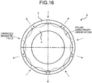
- FIG. 16 is a diagram of a state in which the rotor magnet 3 is polar-anisotropically oriented by an oriented magnetic field on the outer side.
- FIG. 17 is an enlarged view of the rotor magnet 3 shown in FIG. 15B .
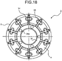
- FIG. 18 is an enlarged view of the rotor magnet 3 shown in FIG. 15C .
- FIG. 19 is a perspective view of the rotor magnet 3, from which the runners are not cut off yet, viewed from the runner side.
- FIG. 20 is an enlarged perspective view of the vicinity of the rib-like runners 35 shown in FIG. 19 .
- FIG. 21 is a partial plan view of the flow of the resin magnet during molding of the rotor magnet 3.
- FIG. 22 is a perspective view of the rotor magnet 3, from which the runners are cut off, viewed from a pedestal sections 50 side.
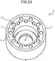
- FIG. 23 is a perspective view of the rotor magnet 3 viewed from the recesses 6 side.
- the rotor magnet 3 is explained with reference to FIGS. 15 to 23 .
- the rotor magnet 3 in this embodiment is obtained by housing the yoke 4 in the lower mold (not shown) of the mold set in the vertical molding machine, injection-molding a resin magnet of thermoplastic resin containing, for example, samarium iron, which is rare earth metal, in the outer circumference of the yoke 4, and integrating the resin magnet 5.
- a strong magnet is arranged to provide an oriented magnetic field on the outer side of the section of the mold where the outer circumference of the resin magnet 5 is formed. Consequently, magnetic particles contained in the resin magnet 5 are oriented anisotropically with respect to the polar direction (see FIG. 16 ).
- a core section of the mold for molding the resin magnet 5 into which the hollow section of the yoke 4 is inserted is formed in the lower mold (not shown in the figure).
- the yoke 4 is inserted into the core section from the axial direction end face including the recesses 6 and assembled in the mold.
- an end face of the core section of the lower mold for molding the resin magnet 5 is an end face position including the pedestals 34 of the yoke 4 (see FIG. 17 ).
- Protrusions fit in the cutouts 7 provided in the axial direction end face on the recesses 6 side of the yoke 4 are provided in the core section (the lower mold) of the mold for molding the resin magnet 5. Consequently, positioning in the circumferential direction with respect to the position of a magnet for creating an oriented magnetic field is performed.
- Resin injecting sections in molding the resin magnet 5 are provided in a doughnut-like runner 36 (see FIGS. 17 to 19 ), which is formed on the end face of the core section (the lower mold) of the mold for molding the resin magnet 5, in the circumferential direction at substantially equal pitches by a half of the number of magnetic poles (a half of ten, i.e., five).
- the resin injecting sections used in molding the resin magnet 5 are left as resin injecting section traces 36a in the doughnut-like runner 36 (see FIG. 18 ).
- the resin injecting section trace 36a is formed substantially in the middle of any two of the ten formed rib-line runners 35.
- the doughnut-like runner 36 projects to the pedestal side from the end face of the resin magnet 5 or the yoke 4 generally at the height (in the axial direction) of the pedestals 34 of the yoke 4.
- the rib-like runners 35 are radially extended from the outer circumference of the doughnut-like runner 36 toward the resin magnet 5 by the same number as the number of magnetic poles (ten).
- the resin injecting section (the resin injecting section trace 36a) in molding the resin magnet 5 is provided in the substantially middle position of two rib-like runners 35.
- the doughnut-like runner 36 and the rib-like runners 35 are formed by the upper mold. Therefore, the doughnut-like runner 36 and the rib-like runners 35 are formed in a taper shape decreasing in size from the end face of the core section (the lower mold) to the axial direction outer side. Consequently, sticking of the doughnut-like runner 36 and the rib-like runners 35 to the upper mold during the mold opening is reduced.
- FIG. 17 Concerning the taper shape of the doughnut-like runner 36 decreasing in size from the end face of the core section (the upper mold) to the axial direction outer side, FIG. 17 is referred to.
- FIG. 20 Concerning the taper shape of the rib-like runners 35 decreasing in size from the end face of the core section (the lower mold) to the axial direction outer side, FIG. 20 is referred to.
- the end face of the core section (the lower mold) is dug straight in a concave shape to predetermined depth (the axial direction). Consequently, resistance to sticking of the doughnut-like runner 36 to the upper mold in mold releasing is generated. Therefore, the lower mold is smoothly separated from the doughnut-like runner 36.
- the rib-like runners 35 radially extending from the doughnut-like runner 36 reach the opening section 34b (see FIG. 9 ) on the inner circumferential side of the pedestals 34 extending across the axial direction end face of the core section (the lower mold) of the mold for molding the resin magnet 5 and the axial direction end face on the pedestal 34 side of the yoke 4. Further, the rib-like runners 35 extend to a predetermined position from the outer circumference of the yoke 4 on an axial direction end face of the resin magnet 5 further on the outer side than the opening section 34b on the outer circumferential side of the pedestals 34.
- the resin magnet flows in the axial direction in a not-shown runner (an axial runner) and changes the direction of its flow by 90° in the resin injecting section (the resin injecting section trace 36a). That is, the resin magnet branches into two in the directions of the arrows (axial orthogonal directions) shown in the resin injecting section trace 36a. Thereafter, the respective resin magnets that have branched into two enter the rib-like runner 35 closest to the resin injecting section (the resin injecting section trace 36a), further change the directions of the flow by 90°, and flow into the resin magnet 5.
- a section where the flowing direction of the resin magnet is changed (the resin injecting section (the resin injecting section trace 36a), a section where the resin magnet flows through the axial runner in the axial direction and branches into two in the axial orthogonal directions) can be set within the mold.
- the doughnut-like runner 36 including the resin injecting sections (the resin injecting section traces 36a) are present further on the inner side than the inner circumference of the yoke 4.
- the section where the flowing direction of the resin magnet is changed (the resin injecting section (the resin injecting section trace 36a), the section where the resin magnet flows in the axial direction and branches into two in the axial orthogonal directions) is present in the mold. Therefore, because the resin magnet flowing through the axial runner in the axial direction branches into two in the axial orthogonal directions in the resin injecting section trace 36a, it is less likely that the yoke 4 and the like are damaged. Consequently, it is possible to attain improvement of the quality in manufacturing.
- the hollow section of the yoke 4 from the end face on the pedestal 34 side to the mold matching surface trace 46 is formed as the straight section 44 (see FIG. 14 ) having a substantially fixed diameter of a circle in cross section. Further, in the hollow section of the yoke 4, a gap of the core section (the lower mold) of the mold for molding the resin magnet 5 fit in the straight section 44 from the end face on the pedestal 34 side is set as small as possible. Consequently, it is possible to suppress a leak of the resin magnet to the gap between the straight section 44 from the end face on the pedestal 34 side to the mold matching surface trace 46 in the hollow section of the yoke 4 and the core section (the lower mold) of the mold for molding the resin magnet 5. Therefore, it is possible to improve the quality during manufacturing.
- the thickness of the resin magnet 5 is set as small as possible.
- the resin injecting sections for directly injecting the resin magnet into the resin magnet 5 need to be reduced in size to match the thickness of the resin magnet 5.
- the resin injecting sections are reduced in size, molding pressure increases.
- the runners are formed by the doughnut-like runner 36 and the rib-like runners 35 radially extending from the outer circumference of the doughnut-like runner 36 in the direction of the resin magnet 5 by a number the same as the number of magnetic poles and the resin injecting sections (the resin injecting section traces 36a) are provided in the doughnut-like runner 36, it is possible to arbitrarily set a gate diameter of the resin injecting sections. Therefore, it is possible to attain an improvement of the quality in manufacturing.
- the number of the resin injecting sections (the resin injecting section traces 36a) of the resin magnet is reduced to a half (five) of the number of the magnetic poles (ten), it is possible to reduce the ratio of the runner amount to the product (the resin magnet 5) compared with the ratio obtained when the provided number of the resin injecting sections for the resin magnet is the same as the number of the magnetic poles.
- the total amount of runner is the total amount of the doughnut-like runner 36, the rib-like runners 35, and not-shown other runners.
- the "runner” is defined as a section not to be formed as the product (the resin magnet 5) between the resin magnet 5 and resin-magnet injecting sections of the mold. Specifically, the “runner” indicates the doughnut-like runner 36, the rib-like runners 35, and the not-shown other runners.
- a part of the rib-like runners 35 are formed as the product.
- the not-shown other runners axial runners
- the doughnut-like runner 36 and the rib-like runners 35 (excluding the sections from the inner circumferential surfaces to the distal ends (in the radial direction) of the pedestals 34 of the yoke 4) are cut off after the completion of the molding of the rotor magnet 3 (see FIG. 22 ).
- the runner amounts of the runners (the other runners, the doughnut-like runner 36, and the rib-like runners 35 (excluding a part)) in this embodiment can be reduced by about 30% compared with the runner amount obtained when the provided number of resin injecting sections for the resin magnet is the same as the number of the magnetic poles (ten).
- the ratio of the axial runner amount to the total runner amount is large compared with the ratio of the other doughnut-like runner 36 and rib-like runners 35. Therefore, when the resin injecting sections are reduced, the total runner amount also decreases.
- the rotor magnet 3 includes the five resin injecting sections for the resin magnet.
- the total runner amount decreases compared with the total runner amount obtained when the provided number of resin injecting sections is the same as the number of the magnetic poles (ten) .
- the reuse ratio decreases because the runner amount of the rotor magnet 3 decreases compared with the runner amount obtained when the provided number of resin injecting sections for the resin magnet is the same as the number of the magnetic poles (ten). Consequently, it is possible to suppress deterioration in the physical properties (mainly mechanical strength) of the resin magnet. Therefore, it is possible to attain an improvement of the quality of the product.
- the number of the resin injecting sections is a half of the number of the magnetic poles
- the number of the rib-like runners 35 is the same as the number of the magnetic poles. Therefore, injection states of the resin magnet into the respective magnetic poles are the same. It is possible to uniformalize states of orientations and attain an improvement of the quality in manufacturing.
- the not-shown other runners, the doughnut-like runner 36, and the rib-like runners 35 are cut off after the completion of the molding of the rotor magnet 3.
- the section of the rib-like runners 35 to the inner circumferential surfaces of the pedestals 34 of the yoke 4 radially extending from the doughnut-like runner 36 are cut off.
- the pedestal sections 50 are configured by the projecting sections 34a of the pedestals 34 of the yoke 4 and non-cutoff sections of the rib-like runners 35 extending to the outer side in the radial direction from between the projecting sections 34a.
- the non-cutoff sections of the rib-like runners 35 include, at the distal ends in the radial direction, magnet holding protrusions for position detection 35b projecting to the axial direction outer side.
- the position detection magnet 11 (see FIG. 1 ) is arranged on the upper surfaces of the pedestals 34 and the rib-like runners 35 (the sections left as the product) (in a substantially horizontal state) on the inner side of the magnet holding protrusions for position detection 35b (see FIG. 22 ) of the pedestal sections 50 of the rotor magnet 3.
- a centrifugal force acts on the position detection magnet 11.
- the magnet holding protrusions for position detection 35b are present around the position detection magnet 11, the magnet holding protrusions for position detection 35b prevent positional deviation in the radial direction.
- the position detection magnet 11 is less likely to drop from the rotor magnet 3. Consequently, productivity is improved.
- Sections of the rib-like runners 35 formed in the resin magnet 5 further on the outer side than the yoke 4 are used as positioning protrusions functioning as positioning in the circumferential direction when the rotor magnet 3 is molded integrally with the shaft 1 by the resin section 17.
- the positioning protrusions functioning as positioning in the circumferential direction when the rotor magnet 3 is formed integrally with a rotor core (explained below) (the sections further on the outer side than the yoke 4 of the rib-like runner 35), the magnet holding protrusions for position detection 35b, and the pedestals 34 are formed by only the resin magnet, there is a drawback in that, when the doughnut-like runner 36 and the rib-like runners 35 are cut off, strength is low because the positioning protrusions, the magnet holding protrusions for position detection 35b, and the pedestals 34 are coupled only by the resin injecting sections to the resin magnet 5 to the resin magnet 5, which is formed in the outer circumference of the yoke 4.
- the pedestals 34 is formed in the yoke 4 and, further, the centers of the pedestals 34 are opened to provide the opening sections 34b, and the rib-like runners 35 are integrated with the pedestals 34 to improve strength. Consequently, it is possible to attain an improvement of the quality in manufacturing.
- the rib-like runners 35 and the doughnut-like runner 36 further on the inner side than the side surfaces on the inner circumferential side of the pedestals 34 are cut off. Consequently, the rotor magnet 3 in this embodiment is obtained.
- the positioning protrusions the sections further on the outer side than the yoke 4 of the rib-like runner 35
- the magnet holding protrusions for position detection 35b, and the pedestals 34 are formed by only the resin magnet
- the position detection magnet 11 (explained below) is not used, because the pedestal sections 50 for the position detection magnet 11 are made unnecessary, the doughnut-like runner 36 and the rib-like runners 35 can be completely cut off.
- FIG. 24A is a side view of a yoke 104 viewed from a recesses 106 side.
- FIG. 24B is a D-D sectional view of FIG. 24A.
- FIG. 24C is a side view of the yoke 104 viewed from the opposite side of recesses 106.
- FIG. 25 is an enlarged view of the yoke 104 shown in FIG. 24C .
- FIG. 26 is a perspective view of the yoke 104 viewed from the opposite side to the recesses 106.
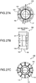
- FIG. 27A is a side view of a modification of a rotor magnet 103, from which runners are not cut off yet, viewed from the recesses 106 side.
- FIG. 27B is an E-E sectional view of FIG.
- FIG. 27A is a side view of a modification of the rotor magnet 103, from which the runners are not cut off yet, viewed from the opposite side to the recesses 106.
- FIG. 28 is an enlarged view of the rotor magnet 103 shown in FIG. 27C .
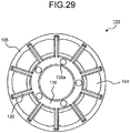
- FIG. 29 is an enlarged view of the rotor magnet 103 shown in FIG. 27C .
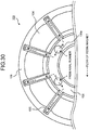
- FIG. 30 is a partial plan view of the flow of a resin magnet during molding of the rotor magnet 103 shown in FIG. 27 .
- FIG. 31 is a partial perspective view of the rotor magnet 103 shown in FIG. 27 , from which the runners are not cut off yet, viewed from the runner side.
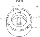
- FIG. 32 is a perspective view of the rotor magnet 103 shown in FIG. 27 , from which the runners are cut off, viewed from the opposite side of the recesses 106.
- the rotor magnet 103 provided when the position detection magnet 11 is not used is explained with reference to FIGS. 24 to 32 .
- the rotor magnet 103 includes the yoke 104 and a resin magnet 105 formed in the outer circumference of the yoke 104.
- the rotor magnet 103 includes ten poles like the rotor magnet 3.
- the yoke 104 is explained. As shown in FIGS. 24A and 24B , the configuration on the recesses 106 side of the yoke 104 is the same as the configuration of the yoke 4 shown in FIG. 6 .
- the yoke 104 is characterized in that the pedestals 34 present in the yoke 4 shown in FIG. 6 are absent on the axial direction end face on the opposite side of the recesses 106 of the yoke 104 ( FIGS. 24 to 26 ).
- the yoke 104 provided on the inner side of the rotor magnet 103 is obtained by injection-molding thermoplastic resin containing a soft magnetic material or ferrite.
- a strong magnet is arranged to provide an oriented magnetic field on the outer side of the section of a mold forming the outer circumference of the yoke 104. Consequently, the soft magnetic material or the ferrite contained in the yoke 104 is anisotropically oriented with respect to a polar direction.
- the yoke 104 is formed in a substantially cylindrical shape in cross section.
- concave sections 147 and convex sections 148 are alternately arranged.
- the number of each of the concave sections 147 and the convex sections 148 is ten.
- the concave sections 147 in the outer circumference of the yoke 104 correspond (are opposed) to magnetic poles of the resin magnet 105.
- the convex sections 148 in the outer circumference of the yoke 104 correspond (are opposed) to interpole spaces of the resin magnet 105.
- the rotor magnet 103 is explained. As shown in FIGS. 27A and 27B , the configuration on the recesses 106 side of the rotor magnet 103 is the same as the configuration of the rotor magnet 3 shown in FIG. 15 .
- the position detection magnet 11 (explained below) is not used, it is unnecessary to form pedestals on an axial direction end face on the opposite side of the recesses 106 of the rotor magnet 103. Therefore, in the rotor magnet 103, from which the runners have not been cut off yet, as shown in FIGS. 27C and 29 , a doughnut-like runner 136 and rib-like runners 135 are only formed on the axial direction end face on the opposite side of the recesses 106.
- a core section of the mold for molding the resin magnet 105 into which a hollow section of the yoke 104 is inserted is formed in a lower mold (not shown in the figures).
- the yoke 104 is inserted into the core section from an axial direction end face including the recesses 106 and assembled in the mold.
- an end face of the core section of the lower mold for molding the resin magnet 105 is located in an axial direction end face on the opposite side of the end face of the yoke 104 on which the recesses 106 are provided (see FIG. 28 ).
- Protrusions fit in cutouts 107 included in the axial direction end face on the recesses 106 side of the yoke 104 are provided in the core section (the lower mold) of the mold for molding the resin magnet 105. Consequently, positioning in the circumferential direction with respect to the position of a magnet for creating an oriented magnetic field is performed.
- Resin injecting sections in molding the resin magnet 105 are provided in a doughnut-like runner 136 (see FIG. 29 ), which is formed on the end face of the core section (the lower mold) of the mold for molding the resin magnet 105, in the circumferential direction at substantially equal pitches by a half of the number of magnetic poles (a half of ten, i.e., five).
- the resin injecting sections in molding the resin magnet 105 are left as resin injecting section traces 136a in the doughnut-like runner 136 (see FIG. 29 ).
- the resin injecting section trace 136a is formed substantially in the middle of any two of the ten formed rib-line runners 135.
- the doughnut-like runner 136 projects to the outer side (the axial direction) from the end face of the resin magnet 105 or the yoke 104 generally substantially at the height (in the axial direction) of the rib-like runners 135.
- the rib-like runners 135 are radially extended from the outer circumference of the doughnut-like runner 136 toward the resin magnet 105 for the same number as the number of magnetic poles (ten).
- the rib-like runners 135 are formed at substantially the same height (in the axial direction) as the doughnut-like runner 136.
- the resin injecting section (the resin injecting section trace 136a) in molding the resin magnet 105 is provided in the substantially middle position of the rib-like runners 135.
- the doughnut-like runner 136 and the rib-like runners 135 are formed by the upper mold. Therefore, the doughnut-like runner 136 and the rib-like runners 135 are formed in a taper shape decreasing in size from the end face of the core section (the lower mold) to the axial direction outer side. Consequently, sticking of the doughnut-like runner 136 and the rib-like runners 135 to the upper mold during the mold opening is reduced.
- FIG. 28 Concerning the taper shape of the doughnut-like runner 136 decreasing in size from the end face of the core section (the upper mold) to the axial direction outer side, FIG. 28 is referred to.
- FIG. 31 Concerning the taper shape of the rib-like runners 135 decreasing in size from the end face of the core section (the lower mold) to the axial direction outer side, FIG. 31 is referred to.
- the end face of the core section (the lower mold) is dug straight in a concave shape to a predetermined depth (the axial direction). Consequently, resistance against sticking of the doughnut-like runner 136 to the upper mold in mold opening is generated. Therefore, the lower mold is smoothly separated from the doughnut-like runner 136.
- the rib-like runners 135 radially extending from the doughnut-like runner 136 extend to predetermined positions from the outer circumference of the yoke 104 across the axial direction end face of the core section of the lower mold for molding the resin magnet 105 and then across the end face of the yoke 104.
- the resin magnet flows in the axial direction in a not-shown runner (an axial runner) and changes the direction of its flow by 90° in the resin injecting section (the resin injecting section trace 136a). That is, the resin magnet branches into two in the directions of the arrows (axial orthogonal directions) shown in the resin injecting section trace 136a. Thereafter, the respective resin magnets branched into two enter the rib-like runner 135 closest to the resin injecting section (the resin injecting section trace 136a) and flow into the resin magnet 105.
- a section where the flowing direction of the resin magnet is changed (the resin injecting section (the resin injecting section trace 136a), a section where the resin magnet flows through the axial runner in the axial direction and branches into two in the axial orthogonal directions) can be set within the mold.
- the doughnut-like runner 136 including the resin injecting sections (the resin injecting section traces 136a) are present further on the inner side than the inner circumference of the yoke 104.
- the section where the flowing direction of the resin magnet is changed (the resin injecting section (the resin injecting section trace 136a) and the section where the resin magnet flows in the axial direction and branches into two in the axial orthogonal directions) are present in the mold. Therefore, it is less likely that the resin magnet flowing through the axial runner in the axial direction damages the yoke 104 and the like. Consequently, it is possible to attain improvement of the quality in manufacturing.
- the hollow section of the yoke 104 from the axial direction end face on the opposite side of the recesses 106 (the cutouts 107) to mold matching surface traces 146 is formed as a straight section 144 (see FIG. 32 ) having a substantially fixed diameter of a circle in cross section. Further, in the hollow section of the yoke 104, a gap of the core section (the lower mold) of the mold for molding the resin magnet 105 fit in the straight section 144 from the opposite side axial direction of the recesses 106 (the cutouts 107) is set as small as possible.
- the thickness of the resin magnet 105 is set as small as possible. In that case, the resin injecting sections for directly injecting the resin magnet into the resin magnet 105 need to be reduced in size to match the thickness of the resin magnet 105. When the resin injecting sections are reduced in size, molding pressure increases.
- the runners are formed by the doughnut-like runner 136 and the rib-like runners 135 radially extending from the outer circumference of the doughnut-like runner 136 in the direction of the resin magnet 105 for the number same as the number of magnetic poles and the resin injecting sections (the resin injecting section traces 136a) are provided in the doughnut-like runner 136, it is possible to arbitrarily set a gate diameter of the resin injecting sections. Therefore, it is possible to attain an improvement of the quality in manufacturing.
- the number of the resin injecting sections (the resin injecting section traces 136a) of the resin magnet is reduced to a half (five) of the number of the magnetic poles (ten), it is possible to reduce the ratio of the runner amount to the product (the resin magnet 105) compared with the ratio obtained when the resin injecting sections for the resin magnet are provided for the same number of the magnetic poles.
- the runner amount is the total amount of the doughnut-like runner 136, the rib-like runners 135, and not-shown other runners.
- the "runner” is defined as a section not to be formed as the product (the resin magnet 105) between the resin magnet 105 and a resin-magnet injecting sections of the mold. Specifically, the "runner” indicates the doughnut-like runner 136, the rib-like runners 135, and the not-shown other runners.
- the not-shown other runners, the doughnut-like runner 136, and the rib-like runners 135 are cut off after the completion of the molding of the rotor magnet 103 (see FIG. 32 ).
- the runner amounts of the runners in this embodiment can be reduced by about 30% compared with the runner amount obtained when the resin injecting sections for the resin magnet are provided for the same number of the magnetic poles (ten).
- the ratio of the other runner amount to the total runner amount is large compared with the ratio of the other doughnut-like runner 36 and rib-like runners 35. Therefore, when the resin injecting sections are reduced, the total runner amount also decreases.
- the rotor magnet 103 includes the five resin injecting sections for the resin magnet.
- the total runner amount decreases compared with the total runner amount obtained when the resin injecting sections for the rein magnet are provided for the same number of the magnetic poles (ten).
- the number of the resin injecting sections is a half of the number of the magnetic poles
- the number of the rib-like runners 135 is the same as the number of the magnetic poles. Therefore, injection states of the resin magnet into the respective magnetic poles are the same. It is possible to uniformalize states of orientations and attain an improvement of the quality of the product.
- Cutoff traces 151 of the cutoff of the rib-like runners 135 are left for the number of the rib-like runners 135 (ten) on the axial direction end face on the opposite side to the recesses 106 (the cutouts 107) of the resin magnet 105.
- the pedestals 34 and a part of the rib-like runners 35 provided in the rotor magnet 3 are absent on the axial direction end face on the opposite side of the recesses 106 (the cutouts 107). Therefore, after the integral molding by the thermoplastic resin, regions for transmitting torque generated by the resin magnet 105 to a rotor core (explained below) are only a part of the cutouts 107 of the yoke 104 and the recesses 106 of the gate (see FIG. 28 ).
- the rotor magnet 3, 103 in which the outer circumference of the yoke 4, 104 is formed in a concave-convex shape and the resin magnet 5, 105 is integrally formed in the outer circumference, is used.
- the rotor magnet 3, 103 can be formed by molding the resin magnet 5, 105 in the outer circumference of the yoke 4, 104 formed in a circular shape in the outer circumference, in a part of which a concave shape or a convex shape is provided.
- the rotor magnet 3, 103 can be configured by only the resin magnet.
- the rotor magnet 3, 103 can be formed by bonding a baked magnet or a molded resin magnet to the yoke 4, 104.
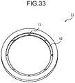
- FIG. 33 is a perspective view of the position detection magnet 11 shown in FIG. 1 .
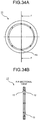
- FIG. 34A is a plan view of the position detection magnet 11.
- FIG. 34B is an F-F sectional view of FIG. 34A .
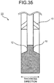
- FIG. 35 is a partially enlarged view of the position detection magnet 11.
- the position detection magnet 11 is explained with reference to FIGS. 33 to 35 .
- the ring-like position detection magnet 11 includes steps 12 at both ends in the axial direction on the inner diameter side and is symmetrical in the thickness direction.
- the position detection magnet 11 is provided at one end in the axial direction of the rotor resin assembly 100 shown in FIGS. 1 to 5 .
- the resin section 17 such as PT (polybutylene terephthalate) is filled in the steps formed at both the ends in the axial direction on the inner side of the position detection magnet 11. Consequently, the steps 12 function as a stopper in the axial direction for the position detection magnet 11.
- the position detection magnet 11 has a symmetrical shape in the thickness direction, the position detection magnet 11 can be set in the mold without changing direction. Therefore, a work time is reduced and improvement of productivity and a reduction in costs can be attained.
- the position detection magnet 11 including the steps 12 at both the ends is shown.
- the position detection magnet 11 can be configured such that the step 12 is provided at one of the ends (the axial direction end face of the position detection magnet 11) and the step 12 is located on the axial direction end side of the rotor resin assembly 100.
- the position detection magnet 11 includes ribs 13 functioning as whirl stops when the resin section 17 (see FIG. 1 ) is filled therein.
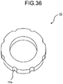
- FIG. 36 is a perspective view of the rotor core 10.
- the rotor core 10 is formed by laminating a predetermined number of electromagnetic steel plates having predetermined thickness (equal to or smaller than 1 mm) substantially in a doughnut shape by caulking or welding to have thickness of 5 to 10 mm.
- predetermined thickness equal to or smaller than 1 mm
- cutouts 10a functioning as whirl stops when the resin section 17 is filled therein are formed.
- holes functioning as whirl stops when embedded in the thermoplastic resin can be provided near the outer circumference of the rotor core 10.
- a predetermined gap e.g., a gap (at least 1.5 mm) equal to or larger than the thickness with respect to the radial direction of the resin magnet 5 (the resin section) formed in the outer circumference of the rotor magnet 3) is secured between the outer circumference of the rotor core 10 and the inner circumference of the rotor magnet 3. Consequently, when the rotor magnet 3 is integrated by the thermoplastic resin, a channel of the thermoplastic resin can be formed between the outer circumference of the rotor core 10 and the inner circumference of the rotor magnet 3. Therefore, it is possible to attain an improvement of the quality in manufacturing.
- a predetermined gap e.g., a gap (at least 1.5 mm) equal to or larger than the thickness with respect to the radial direction of the resin magnet 5 (the resin section) formed in the outer circumference of the rotor magnet 3
- the yoke 4 of the rotor magnet 3 electrically functions as an insulating layer when the rotor resin assembly 100 is assembled to a shaft (the shaft 1). Therefore, because electrolytic corrosion resistance of a bearing is improved, it is possible to attain an improvement of the quality.
- the rotor resin assembly 100 in this embodiment is obtained by integrating the rotor magnet 3, the position detection magnet 11, and the rotor core 10 by injection-molding thermoplastic resin such as PBT (polybutylene terephthalate).
- thermoplastic resin such as PBT (polybutylene terephthalate).
- the rotor core 10 and the rotor magnet 3 are inserted and assembled from the end face on the side including the recesses 6 of the yoke 4.
- the rotor core 10 is set in substantially the center of the rotor magnet 3 by the mold cored bar section (see FIG. 1 ). Consequently, the rotor core 10 is set in the position of the center of gravity of the rotor magnet 3 and a reduction in noise and a reduction in vibration of the electric motor can be attained.
- the upper mold is closed and thermoplastic resin such as PBT is injected.
- thermoplastic resin such as PBT
- FIG. 37 is a front view of a rotor shaft assembly 150 in which the rotor resin assembly 100 is assembled to the shaft 1 by caulking.
- the shaft 1 is inserted into an inner diameter section of the rotor core 10, and the rotor resin assembly 100 is crushed (caulked) by a jig to form a recess in the vicinity of the inner diameter sections of both the end faces of the rotor core 10 and assembled to the shaft 1.
- the resin section 17 (see FIG. 1 ) is formed on both the end faces of the rotor core 10 from the outer circumference of the rotor core 10 to a predetermined distance on the inner circumferential side. Consequently, the outer circumference of the rotor core 10 is suppressed from widening in the axial direction in the caulking (when pressed by the jig). Therefore, it is possible to attain an improvement of the quality in manufacturing.
- E-ring grooves 1a in which E rings (explained below) are assembled, are formed in predetermined positions from both of the end face sides of the rotor resin assembly 100.
- FIG. 38 is a front view of a rotor 200 in which E rings 420 and bearings 410 are assembled to the shaft 1 shown in FIG. 37 .
- shaft length is limited to the mold opening amount in resin molding.
- molds for respective positions are necessary.
- the rotor 200 in this embodiment is released from such limitations.
- the rotor magnet 3 is used in which the outer circumference of the yoke 4 is formed in a wavy shape (a curved concave shape and a curved convex shape) and the resin magnet 5 is integrally molded in the outer circumference.
- the rotor magnet 3 can be formed by forming the outer circumference of the yoke 4 in a circular shape and providing a concave shape or a convex shape in a part of the outer circumference and then molding the resin magnet 5 in the outer circumference of the yoke 4.
- the rotor magnet 3 can be formed by bonding a baked magnet or a molded resin magnet to the yoke 4. It goes without saying that, no matter what the outer circumference shape of the yoke 4 and the material of the magnet arranged in the outer circumference are, the outer circumference shape and the material are included in this embodiment as long as the configuration of the rotor magnet 3 is the same as the configuration in this embodiment.
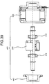
- FIG. 39 is an exploded front view of a mold motor 400 according to the embodiment of the present invention before assembly.
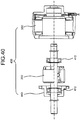
- FIG. 40 is an exploded front view of the mold motor 400 before assembly in a state in which a bracket 440 is fit in the bearings 410.
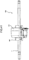
- FIG. 41 is a front view of the mold motor 400.
- the mold motor 400 includes a mold stator 350, the rotor 200, and the bracket 440 (explained below).
- the bracket 440 is fit in one bearing 410 (provided on the opposite side of the position detection magnet 11).
- the fitting of the bracket 440 and the one bearing 410 is a loose fitting.
- a wavy washer is provided in a gap in the axial direction between the bracket 440 and the one bearing 410.
- the wavy washer can be provided in a gap in the axial direction between the mold stator 350 and the other bearing 410.
- FIG. 42 is a perspective view of the mold stator 350.
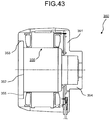
- FIG. 43 is a sectional view of the mold stator 350.
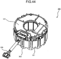
- FIG. 44 is a perspective view of a stator 300.
- the stator 300 in this embodiment includes lead wires 306 connected to the outside after insulating sections 303 are applied to a stator iron core 301 and a magnet wire is wound around the insulating sections 303 formed in a teeth section. Further, in the stator 300, a substrate 310 mounted with a driving circuit (explained below) is provided at a wire bound side end of the stator 300.
- the stator 300 is molded with thermosetting resin (mold resin 351) such as BMC resin (Bulk Molding Compound, lump clay-like thermosetting resin obtained by adding various additives to unsaturated polyester resin) to be formed as the mold stator 350.
- mold resin 351 such as BMC resin (Bulk Molding Compound, lump clay-like thermosetting resin obtained by adding various additives to unsaturated polyester resin)
- an opening section 352 formed by a cored bar section of a die for molding the mold stator 350 and a bracket press-fitting section 353 provided near the opening section 352 and formed at a diameter larger than a stator diameter are formed.
- a fitting section of the inner diameter section of the stator 300 and a fitting section of a bearing housing section 354 on one side are formed by the cored bar section of the die, coaxiality of which with the bracket press-fitting section 353 is secured, whereby coaxiality of the rotor 200 with respect to the stator 300 is secured. Consequently, the high-quality mold motor 400 having low noise and low vibration can be obtained. It is possible to attain improvement of electrolytic corrosion resistance of the bearing 410 by forming a bearing housing section 354 only with resin that is electrically insulated.
- FIG. 45 is a sectional view of the bracket 440.
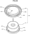
- FIG. 46 is an exploded perspective view of the bracket 440.
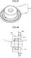
- FIG. 47 is a perspective view of the bracket.
- FIG. 48 is a partially enlarged view of a state in which the bracket 440 fit in the bearing 410 is press-fit into the mold stator 350.
- FIG. 48 is a partially enlarged view of the mold motor 400. In the following explanation, explanation of the figure is omitted.
- the bracket 440 is configured from a bracket sheet metal section 442 and a bracket resin section 441.
- the bracket sheet metal section 442 and the bracket resin section 441 are respectively manufactured in separate processes.
- the bracket 440 is configured by combining the bracket sheet metal section 442 and the bracket resin section 441.
- the bracket sheet metal section 442 of the bracket 440 is configured as a press-fitting section into the mold stator 350.
- the bracket resin section 441 of the bracket 440 is configured as a bearing housing section.
- bracket resin section 441 to be formed as the bearing housing section of the bracket 440 is formed by only electrically insulated resin together with the bearing housing section 354 (see FIG. 43 ) of the mold stator 350. Consequently, it is possible to attain an improvement of the electrolytic corrosion resistance of the bearing 410. Therefore, the quality of the mold motor 400 is improved.
- the outer circumferential surface diameter of the bracket resin section 441 is set to a dimension that is the same as the outer circumferential surface diameter of the bearing housing section 354 (see FIG. 43 ), in an electric motor in which a rubber vibration insulator (not shown in the figure) is attached to the outer circumference of the bearing housing section 354, the same component (the rubber vibration insulator) can be used for the outer circumferential surface of the bracket resin section 441. Therefore, it is possible to attain a reduction in manufacturing costs and an improvement of the quality in manufacturing.
- the bracket sheet metal section 442 of the bracket 440 shown in FIG. 45 are bent in three places.
- An opening section 442g of the bracket sheet metal section 442 is formed in a diameter larger than the outer circumference of a bearing housing section 441b of the bracket resin section 441.
- a protrusion 441d functioning as a whirl stop is formed on the axial direction setting surface 441c of the bracket sheet metal section 442 of the bracket resin section 441.
- a cutout 442e in which the protrusion 441d for a whirl stop for the bracket resin section 441 is fit, is formed.
- the diameter of the press-fitting section 441a of the bracket resin section 441 is set larger than the inner diameter of the stator 300.
- the length in the axial direction of the press-fitting section 441a of the bracket resin section 441 is set the same as the distance between an axial direction setting surface 355 (see FIG. 43 ) of the mold stator 350 and the axial direction setting surface 441c of the bracket resin section 441. Consequently, when the bracket 440 is assembled to the mold stator 350, the bracket resin section 441 is held between the bracket sheet metal section 442 and the mold stator 350 and does not move in the axial direction. Therefore, it is possible to attain an improvement of the quality.
- the bracket sheet metal section 442 is bent in three places.
- the outer circumferential section of the bracket sheet metal section 442 is formed as a section press-fit into the bracket press-fitting section 353 of the mold stator 350.
- a section bent 90° with respect to the outer circumferential section 442a of the bracket sheet metal section 442 is formed as the axial direction setting surface 442b of the bracket press-fitting section 353.
- the section is further bent 90° or less to form an inner wall (the inner circumferential section 442c) and further bent to form a surface (the axial direction setting surface 442d) parallel to a setting surface in the axial direction of the bracket press-fitting section 353.
- the bracket sheet metal section 442 and the bracket resin section 441 are integrated, the rotation of the bracket resin section 441 can be prevented. Therefore, noise and vibration are reduced and it is possible to realize an improvement of the quality.
- FIG. 49 is a diagram of a first modification of the bracket (a bracket 540).
- FIG. 50 is an exploded perspective view of the bracket 540 shown in FIG. 49 .
- FIG. 51 is a perspective view of the bracket 540 shown in FIG. 49 .
- FIG. 52 is a partially enlarged view of a state in which the bearing 410 fit in the bracket 540 shown in FIG. 49 is press-fit into the mold stator 350.
- the bracket 540 in the first modification is explained with reference to FIGS. 49 to 52 .
- the bracket 540 in the first modification is different from the bracket 440 (see FIG. 45 ) in that the outer circumferential surface of a bearing housing section 541b of a bracket resin section 541 is formed as a press-fitting section 541a.
- a cutout 541f is formed in the outer circumference of a brim section 541e having a diameter larger than the press-fitting section 541a.
- the cutout 541f engages with a flat section 542f of a bracket sheet metal section 542 and functions as a whirl stop in a state in which the bracket resin section 541 is press-fit into the bracket sheet metal section 542.
- the bracket sheet metal section 542 shown in FIG. 49 is bent in four places.
- bracket 540 stray capacitance between the bracket sheet metal section 542 and the bearing 410 is within an allowable range.
- the bracket 540 is slightly larger than the bracket 440 (see FIG. 52 )
- the axial direction distance of the press-fitting section 542c of the bracket sheet metal section 542 can be secured for a long time, and the press-fitting section 541a is held in the press-fitting section 542c. Therefore, the press-fitting margin of the brim section 541e into the inner circumferential surface of the bracket sheet metal section 542 can be set small compared with the bracket 440. It is possible to reduce distortion of the bracket sheet metal section 542 and attain an improvement of the quality in manufacturing.
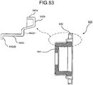
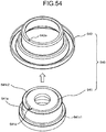
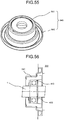
- FIG. 53 is a sectional view of a second modification of the bracket (a bracket 640).
- FIG. 54 is an exploded perspective view of the bracket 640 shown in FIG. 53 .
- FIG. 55 is a perspective view of the bracket 640 shown in FIG. 53 .
- FIG. 56 is a partially enlarged view of a state in which the bracket 640 fit in the bearing 410 is press-fit into the mold stator 350.
- the bracket 640 in the second modification is characterized in that an axial direction setting surface 642d2 bent 90° from a press-fitting section 642c to the inner circumferential side is formed in a bracket sheet metal section 642.
- a cutout 642e functioning as a whirl stop is formed in the bracket sheet metal section 642.
- a bracket resin section 641 is press-fit into and assembled to the bracket sheet metal section 642
- a whirl stop protrusion 641d of the bracket resin section 641 is fit in the cutout 642e of the bracket sheet metal section 642 and functions as a whirl stop.
- the bracket sheet metal section 642 shown in FIG. 53 is bent in five places.
- the bracket 540 in the first modification it is likely that burrs occur on the axial direction end face of the section (the press-fitting section 542c) into which the bracket resin section 541 of the bracket sheet metal section 542 is press-fit. Therefore, processing for removing the burrs is necessary. It is anticipated that costs in manufacturing increase.
- the axial direction setting surface 642d2 is provided on the axial direction setting surface 641c2 of the bracket resin section 641. Therefore, burrs are absent in the section (the press-fitting section 642c) into which the bracket resin section 641 of the bracket sheet metal section 642 is press-fit. Therefore, even when burrs occur at the distal end of the axial direction setting surface 642d2, processing for removing the burrs is unnecessary. It is possible to reduce costs in manufacturing.
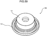
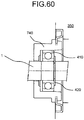
- FIG. 57 is a sectional view of a third modification of the bracket (a bracket 740).
- FIG. 58 is an exploded perspective view of the bracket 740 shown in FIG. 57 .
- FIG. 59 is a perspective view of the bracket 740 shown in FIG. 57 .
- FIG. 60 is a partially enlarged view of a state in which the bracket fit in the bearing 410 is press-fit into the mold stator 350.
- the bracket 740 in the third modification is configured from two kinds of components, i.e., a bracket sheet metal section 742 and a bracket resin section 741.
- the bracket 740 in the third modification is formed by integrally molding the bracket resin section 741 with the bracket sheet metal section 742.
- the bracket sheet metal section 742 forms a press-fitting section that is press-fit into the mold stator 350.
- the bracket resin section 741 forms a bearing housing section.
- bracket resin section 741 functioning as a bearing housing section of the bracket 740 is formed by only electrically insulated resin together with the bearing housing section of the mold stator 350. Consequently, it is possible to attain an improvement of the electrolytic corrosion resistance of the bearing 410. Therefore, the quality of the mold motor 400 is improved.
- the outer circumferential surface diameter of the bracket resin section 741 is set to a dimension that is the same as the outer circumferential surface diameter of the bearing housing section 354 (see FIG. 43 ), in an electric motor in which a rubber vibration insulator (not shown in the figure) is attached to the outer circumferential surface of the bearing housing section of the bearing housing section 354, the same component (the rubber vibration insulator) can be used for the outer circumferential surface of the bracket resin section 741. Therefore, it is possible to attain a reduction in manufacturing costs and an improvement of the quality in manufacturing.
- cutouts 744 functioning as whirl stops when the bracket resin section 741 is filled therein are formed.
- holes functioning as whirl stops when embedded in thermoplastic resin can be provided near the inner circumferential section of the bracket sheet metal section 742.
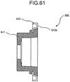
- FIG. 61 is a sectional view of a fourth modification of the bracket (a bracket 840).
- FIG. 62 is a partially enlarged view of a state in which the bracket 840 fit in the bearing 410 is press-fit into the mold stator 350.
- the bracket 840 in the fourth modification is also configured from two kinds of components, i.e., a bracket sheet metal section 842 and a bracket resin section 841.
- the bracket 840 in the fourth modification is also formed by integrally molding the bracket resin section 841 with the bracket sheet metal section 842.
- the bracket sheet metal section 842 forms a press-fitting section that is press-fit into the mold stator 350.
- the bracket resin section 841 forms a bearing housing section.
- the bracket 840 in the fourth modification is different from the bracket 740 in the third modification in that resin is filled up to an axial direction setting surface 842b of the bracket sheet metal section 842 for the bracket press-fitting section 353 (see FIG. 43 ) of the mold stator 350.
- resin is filled up to an axial direction setting surface 842b of the bracket sheet metal section 842 for the bracket press-fitting section 353 (see FIG. 43 ) of the mold stator 350.
- an end face on an electric motor inner side of the bracket resin section 841 is formed the same as a setting surface in the axial direction of the bracket press-fitting section 353 of the mold stator 350 of the bracket sheet metal section 842. Consequently, it is possible to simplify a mold for integrally molding the bracket resin section 841 with the bracket sheet metal section 842. Therefore, it is possible to reduce costs in manufacturing.
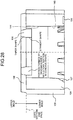
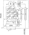
- FIG. 63 is a circuit diagram of a motor-incorporated driving circuit 160 incorporated in the mold motor according to the embodiment of the present invention.
- the motor-incorporated driving circuit 160 is explained with reference to FIG. 63 .
- alternating-current power is supplied from a commercial alternating-current power supply 162 provided on the outside of the mold motor 400 to the motor-incorporated driving circuit 160.
- An alternating-current voltage supplied from the commercial alternating-current power supply 162 is converted into a direct-current voltage by a rectifier circuit 163.
- the direct-current voltage converted by the rectifier circuit 163 is converted into an alternating-current voltage having a variable frequency by an inverter main circuit 164 and applied to the mold motor 400.
- the mold motor 400 is driven by alternating-current power having a variable frequency supplied from the inverter main circuit 164.
- a chopper circuit configured to boost the voltage applied from the commercial alternating-current power supply 162, a smoothing capacitor configured to smooth a rectified direct-current voltage, and the like are provided in the rectifier circuit 163.
- the inverter main circuit 164 is a three-phase bridge inverter circuit.
- a switching section of the inverter main circuit 164 includes six IGBTs 166a to 166f (insulating gate bipolar transistors; simply defined as transistors) functioning as inverter main elements and includes six SiC-SBDs 167a to 167f (schottky barrier diodes; simply defined as diodes), in which silicon carbide (SiC) is used, as flywheel diodes (FRDs).
- the SiC-SBDs 167a to 167f functioning as the FRDs are reverse-current preventing means for suppressing a counter electromotive force that occurs when the IGBTs 166a to 166f change an electric current from ON to OFF.
- the IGBTs 166a to 166f and the SiC-SBDs 167a to 167f are formed as an IC module mounted with chips on the same lead frame, molded with epoxy resin, and packaged.
- the IGBTs 166a to 166f can be IGBTs in which SiC, GaN is used instead of the IGBTs (Si-IGBTs) in which silicon is used.
- Other switching elements such as MOSFETs (Metal-Oxide-Semiconductor Field-Effect Transistors) in which Si or SiC, GaN is used can be used instead of the IGBTs.
- a direct-current-voltage detecting unit 168 configured to sample and hold an electric signal obtained by reducing a high direct-current voltage in a voltage dividing circuit formed by the voltage dividing resistors 168a, 168b is provided.
- the mold motor 400 includes the rotor 200 ( FIG. 38 ) and the mold stator 350 ( FIG. 43 ).
- the rotor 200 rotates due to the alternating-current power supplied from the inverter main circuit 164.
- a Hall IC 49b configured to detect the position detection magnet 11 is provided and a rotor-position detecting unit 170 configured to process an electric signal from the Hall IC 49b and convert the electric signal into position information of the rotor 200 is provided.
- the position information of the rotor 200 detected by the rotor-position detecting unit 170 is output to an output-voltage calculating unit 180.
- the output-voltage calculating unit 180 calculates optimum output voltage of the inverter main circuit 164, which should be applied to the mold motor 400, based on a command of a target number of revolutions N or information concerning an operation condition of an apparatus given from the outside of the motor-incorporated driving circuit 160 and the position information of the rotor 200.
- the output-voltage calculating unit 180 outputs the calculated output voltage to a PWM-signal generating unit 190.
- PWM is an abbreviation of Pulse Width Modulation.
- the PWM-signal generating unit 190 outputs a PWM signal corresponding to the output voltage given from the output-voltage calculating unit 180 to a main element driving circuit 164a configured to drive each of the IGBTs 166a to 166f of the inverter main circuit 164.
- a main element driving circuit 164a configured to drive each of the IGBTs 166a to 166f of the inverter main circuit 164.
- Each of the IGBTs 166a to 166f of the inverter main circuit 164 is switched by the main element driving circuit 164a.
- the inverter main circuit 164 is a three-phase bridge inverter circuit.
- the inverter main circuit 164 can be other inverter circuits such as a single-phase inverter circuit.
- the wide band-gap semiconductor is a general term for a semiconductor having a band-gap larger than the band-gap of Si.
- the SiC used in the SiC-SBDs 167a to 167f is one of wide band-gap semiconductors.
- gallium nitride (GaN), diamond, and the like can be used.
- the wide band-gap semiconductor, in particular, the SiC has higher heat-resistant temperature and larger breakdown strength and thermal conductivity compared with Si.
- the SiC is used in the FRDs of the inverter circuit.
- other wide band-gap semiconductors can be used instead of the SiC.
- FIG. 64 is a diagram of the embodiment and a manufacturing process chart of the mold motor 400.
- the mold motor 400 is manufactured by a process explained below.
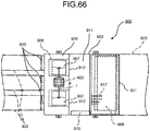
- FIG. 65 is a configuration diagram of a side surface of a ceiling-embedded air conditioner 900 according to the embodiment of the present invention.
- FIG. 66 is a configuration diagram of a plane of the ceiling-embedded air conditioner 900 shown in FIG. 65 .
- the ceiling-embedded air conditioner 900 (an example of an air conditioner) mounted with a blower, in which the mold motor 400 in this embodiment is used as a driving source, is explained with reference to FIGS. 65 and 66 .
- the ceiling-embedded air conditioner 900 incorporates, in a main body casing 902, an indoor-side heat exchanger 908 configured to subject indoor air and a refrigerant to heat exchange to perform air conditioning, a drain pan 909 configured to temporarily store dew condensation water from the indoor-side heat exchanger 908 and a refrigerant pipe, a blower 935 configured to blow the indoor air to the indoor-side heat exchanger 908, and a control box 919 in which electrical components such as a power supply for the blower 935 and a control device are housed.
- the main body casing 902 is formed in a hollow rectangular box shape with left and right side plates, a top plate, a front plate, a rear plate, and a bottom plate of a lower surface rear section.
- the main body casing 902 is set in an air conditioner attachment opening of a ceiling 933.
- the main body casing 902 is suspended from and held on the roof-space via suspension bars connected to holding fixtures protrudingly provided on the side plates.
- the main body casing 902 includes a ventilation route in a casing.
- the main body casing 902 is partitioned into a blowing space 904 and a heat exchange space 905 by a partition plate 903.
- Duct connecting sections 920 respectively including air inlet ports are provided in the front plate of the main body casing 902. Air inlet ducts 922 are coupled to the duct connecting sections 920.
- an air outlet port 921 is formed in the rear plate and coupled to an air outlet duct 923.
- the blower 935 disposed in the blowing space 904 is configured by the mold motor 400 including the shaft 1 of a dual shaft type, blowing fans 907 such as sirocco fans attached to both ends of the shaft 1, and fan casings 906 configured to house the blowing fans 907.
- the fan casings 906 are arranged such that air outlet ports 912 thereof are opened to a work space 911 piercing through the partition plate 903. Drain holes are drilled in the bottom surfaces of the fan casings 906. The drain holes are open-closably sealed by a plug body.
- the work space 911 having breadth capable of receiving a head and an upper half of the body of an operator is provided between the indoor-side heat exchanger 908 and the blower 935 in the main body casing 902.
- the drain pan 909 set below the indoor-side heat exchanger 908 is disposed above the bottom plate.
- an opening section communicating with the work space 911 is formed below the work space 911 in the main body casing 902.
- An opening section is formed below the blowing space 904.
- the opening section is set to a size enough for receiving the head and the upper half of the body of an operator.
- the opening sections are open-closably sealed by a lid plate that swings around a hinge section.
- the control box 919 is set on the side plate in the work space 911.
- a flow-down port coupled to a not-shown drainage hose or the like is provided in the bottom of the drain pan 909.
- a connecting section of refrigerant pipes 916 connected to the indoor-side heat exchanger 908 and the other refrigerant pipes 917 connected to, for example, an outdoor-side heat exchanger (not shown in the figure) is arranged above the drain pan 909 in the main body casing 902.
- Each of the refrigerant pipes 916 is arranged to incline so as to be high on the connecting section side and low on the drain pan 909 side.
- the refrigerant pipes 917 are fixed to the side plate via a pipe cover arranged above the control box 919.
- the fan casings 906, the blowing fans 907, the indoor-side heat exchanger 908, the drain pan 909, the connecting section, the refrigerant pipes 916, the refrigerant pipes 917, the pipe cover, and the control box 919 are arranged in positions around the work space 911 in the main body casing 902 and within the reach of the operator.
- the ceiling-embedded air conditioner 900 is configured as explained above.
- a refrigerant cooled or heated by the outdoor-side heat exchanger and a refrigerant restricting device (neither of which are shown in the figures) forming a refrigerating cycle flows into the indoor-side heat exchanger 908.
- the blowing fans 907 are driven by the startup of the mold motor 400, whereby the indoor air is sucked into the fan casings 906 from the room through the air inlet ducts 922. The air sucked in this way is blown out from the air outlet ports 912. The air reaches the heat exchange space 905 through the work space 911.
- the air is blown out from the air outlet port 921 after being cooled or warmed by heat exchange with the refrigerant in the indoor-side heat exchanger 908.
- the air blown out from the air outlet port 921 is returned to the room from the air outlet duct 923 and cools or warms the room.
- the present invention is applicable to a mold motor and an air conditioner and, in particular, can be easily adapted to a change in specifications and is useful as an invention having resistance to high-frequency electrolytic corrosion.
Landscapes
- Engineering & Computer Science (AREA)
- Power Engineering (AREA)
- Microelectronics & Electronic Packaging (AREA)
- Permanent Field Magnets Of Synchronous Machinery (AREA)
- Iron Core Of Rotating Electric Machines (AREA)
- Manufacture Of Motors, Generators (AREA)
- Brushless Motors (AREA)
Description
- The present invention relates to a rotor of an electric motor assembled to a long or large-diameter shaft. The present invention relates to a mold motor in which the rotor of the electric motor is used. The present invention relates to an air conditioner in which the mold motor is mounted on a blower. Further, the present invention relates to a method of manufacturing the mold motor in which the rotor of the electric motor is used.
- It is proposed to set a cylindrical boss in a permanent magnet and fix a shaft to the boss to configure a rotor of an electric motor. The permanent magnet and the boss can be simultaneously assembled during injection molding of the permanent magnet by injection-molding a ferrite resin magnet or the like to form the permanent magnet. Rotors comprising molded resin are described for example in the patent applications
JP 2006320141 JP 2007306796 - To make it possible to prevent an electric current from flowing to the roller bearing provided between the rotating shaft and the motor case and thereby to prevent electrolytic corrosion from occurring in the roller bearing and to obtain a rotating-electric machine that is simple in configuration and easy to assemble, it is proposed to arrange an insulation sleeve in the outer circumference of the roller bearing (see, for example, Patent Literature 2).
-
- Patent Literature 1: Japanese Patent Application Laid-open No.
2000-188838 - Patent Literature 2: Japanese Patent Application Laid-open No.
2000-156952 - However, in the rotor of the dynamo-electric machine described in
Patent Literature 1, because the shaft is press-fit into the boss and fixed, the outer circumference of the shaft is scratched by the press-fitting process. This affects, for example, accuracy in assembling the roller bearing to the shaft. Therefore, for example, when the shaft is long, there is a problem in that the rotor cannot be easily attached to the shaft and cannot be adapted to any specification changes. - In the dynamo-electric machine described in
Patent Literature 2, an electric current is prevented from flowing to the roller bearing by arranging the insulation sleeve in the outer circumference of the roller bearing. However, there is a problem in that the electric current still flows to the bearing because of stray capacitance between the bracket and the outer ring of the roller bearing. - In document
JP 2006320141 a - In document
JP 2007306796 A - The present invention has been devised in view of the above and provides a rotor of an electric motor, a mold motor, an air conditioner, and a method of manufacturing the mold motor that, with regard to attaching the rotor to a shaft, enable the rotor to be easily attached to the shaft even if the shaft is long, enable the rotor to be attached to an arbitrary position of the shaft, and can be easily adapted to changes in specifications. Methods for attaching a rotor to a shaft are described in the documents
DE 70 45 170 U andDE 10 2007 060 250 A1 - Further, the present invention provides a rotor of an electric motor, a motor, an air conditioner, and a method of manufacturing the motor having resistance to highfrequency electrolytic corrosion.
- In order to solve the aforementioned problems, a rotor of an electric motor is configured in such a manner as to include: a rotor resin assembly; a shaft; and a bearing, wherein the rotor resin assembly includes: a rotor magnet including a substantially cylindrical yoke molded from thermoplastic resin containing a soft magnetic material or ferrite and a resin magnet integrally formed in the outer circumference of the yoke; a position detection magnet arranged at one end in an axial direction of the rotor magnet; and a rotor core arranged in an inner circumference of the rotor magnet and formed by laminating a predetermined number of electromagnetic steel plates, wherein the rotor magnet, the position detection magnet, and the rotor core are integrally formed by resin, and the shaft is inserted into the inner diameter section of the rotor core, and the rotor resin assembly is caulked by a jig to for a recess in the vicinity of inner diameter sections of both end faces of the rotor core and assembled to the shaft.
- In the rotor of the electric motor according to the present invention, with the configuration explained above, it is possible to arbitrarily select the length of the shaft and the position of the rotor resin assembly. Therefore, it is possible to obtain a rotor of an electric motor that can be easily adapted to changes in specifications.
-
-
FIG. 1 is a sectional view of a rotor resin assembly according to an embodiment of the present invention. -
FIG. 2 is a left side view of the rotor resin assembly. -
FIG. 3 is a right side view of the rotor resin assembly. -
FIG. 4 is a perspective view of the rotor resin assembly viewed from a position detection magnet side. -
FIG. 5 is a perspective view of the rotor resin assembly viewed from the opposite side of the position detection magnet. -
FIG. 6A is a side view of a yoke viewed from a recess side. -
FIG. 6B is a B-B sectional view ofFIG. 6A . -
FIG. 6C is a side view of the yoke viewed from the position detection magnet side. -
FIG. 7 is a diagram of a state in which the yoke is polar-anisotropically oriented by an oriented magnetic field on the outer side. -
FIG. 8 is an enlarged view of the yoke shown inFIG. 6A . -
FIG. 9 is an enlarged view of the yoke shown inFIG. 6C . -
FIG. 10 is a perspective view of the yoke viewed from pedestals. -
FIG. 11 is a perspective view of the yoke viewed from the recesses. -
FIG. 12 is a partially enlarged view of the yoke shown inFIG. 11 . -
FIG. 13 is a partially enlarged view of the yoke shown inFIG. 6B . -
FIG. 14 is an enlarged view of the yoke shown inFIG. 6B . -
FIG. 15A is a side view of a rotor magnet, from which runners are not cut off yet, viewed from the recess side. -
FIG. 15B is a C-C sectional view ofFIG. 15A . -
FIG. 15C is a side view of the rotor magnet, from which the runners are not cut off yet, viewed from the position detection magnet side. -
FIG. 16 is a diagram of a state in which the rotor magnet is polar-anisotropically oriented by an oriented magnetic field on the outer side. -
FIG. 17 is an enlarged view of the rotor magnet shown inFIG. 15B . -
FIG. 18 is an enlarged view of the rotor magnet shown inFIG. 15C . -
FIG. 19 is a perspective view of the rotor magnet, from which the runners are not cut yet, viewed from the runner side. -
FIG. 20 is an enlarged perspective view of the vicinity of the rib-like runners shown inFIG. 19 . -
FIG. 21 is a partial plan view of the flow of the resin magnet during molding of the rotor magnet. -
FIG. 22 is a perspective view of the rotor magnet, from which the runners are cut off, viewed from the pedestal section side. -
FIG. 23 is a perspective view of the rotor magnet viewed from the recess side. -
FIG. 24A is a side view of a yoke viewed from the recess side. -
FIG. 24B is a D-D sectional view ofFIG. 24A . -
FIG. 24C is a side view of the yoke viewed from the opposite side to the recesses. -
FIG. 25 is an enlarged view of the yoke shown inFIG. 24C . -
FIG. 26 is a perspective view of the yoke viewed from the opposite side to the recesses. -
FIG. 27A is a side view of a modification of a rotor magnet, from which runners are not cut off yet, viewed from the recess side. -
FIG. 27B is an E-E sectional view ofFIG. 27A . -
FIG. 27C is a modification of the rotor magnet, from which the runners are not cut off yet, viewed from the opposite side of the recesses. -
FIG. 28 is an enlarged view of the rotor magnet shown inFIG. 27C . -
FIG. 29 is an enlarged view of the rotor magnet shown inFIG. 27C . -
FIG. 30 is a partial plan view of the flow of a resin magnet during molding of the rotor magnet shown inFIG. 27 . -
FIG. 31 is a partial perspective view of the rotor magnet shown inFIG. 27 , from which the runners are not cut off yet, viewed from the runner side. -
FIG. 32 is a perspective view of the rotor magnet shown inFIG. 17 , from which the runners are cut off, viewed from the opposite side to the recesses. -
FIG. 33 is a perspective view of the position detection magnet shown inFIG. 1 . -
FIG. 34A is a plan view of the position detection magnet. -
FIG. 34B is an F-F sectional view ofFIG. 34A . -
FIG. 35 is a partially enlarged view of the position detection magnet. -
FIG. 36 is a perspective view of a rotor core. -
FIG. 37 is a front view of a rotor shaft assembly obtained by assembling the rotor resin assembly to the shaft by using caulking. -
FIG. 38 is a front view of the rotor obtained by assembling an E ring and a bearing to the shaft shown inFIG. 37 . -
FIG. 39 is an exploded front view of a mold motor according to the embodiment of the present invention before assembly. -
FIG. 40 is a front view of the mold motor. -
FIG. 41 is a front view of the mold motor. -
FIG. 42 is a perspective view of a mold stator. -
FIG. 43 is a sectional view of the mold stator. -
FIG. 44 is a perspective view of a stator. -
FIG. 45 is a sectional view of a bracket. -
FIG. 46 is an exploded perspective view of the bracket. -
FIG. 47 is a perspective view of the bracket. -
FIG. 48 is a partially enlarged view of a state in which the bracket that is fit in the bearing is press-fit into the mold stator. -
FIG. 49 is a diagram of a first modification of the bracket. -
FIG. 50 is an exploded perspective view of the bracket shown inFIG. 49 . -
FIG. 51 is a perspective view of the bracket shown inFIG. 49 . -
FIG. 52 is a partially enlarged view of a state in which the bracket that is fit in the bearing is press-fit into the mold stator. -
FIG. 53 is a sectional view of a second modification of the bracket. -
FIG. 54 is an exploded perspective view of the bracket shown inFIG. 53 . -
FIG. 55 is a perspective view of the bracket shown inFIG. 53 . -
FIG. 56 is a partially enlarged view of a state in which the bracket that is fit in the bearing is press-fit into the mold stator. -
FIG. 57 is a sectional view of a third modification of the bracket. -
FIG. 58 is an exploded perspective view of the bracket shown inFIG. 57 . -
FIG. 59 is a perspective view of the bracket shown inFIG. 57 . -
FIG. 60 is a partially enlarged view of a state in which the bracket that is fit in the bearing is press-fit into the mold stator. -
FIG. 61 is a sectional view of a fourth modification of the bracket. -
FIG. 62 is a partially enlarged view of a state in which the bracket that is fit in the bearing is press-fit into the mold stator. -
FIG. 63 is a circuit diagram of a motor-incorporated driving circuit incorporated in the mold motor according to the embodiment of the present invention. -
FIG. 64 is a manufacturing process chart of the mold motor according to the embodiment of the present invention. -
FIG. 65 is a configuration diagram of a side surface of a ceiling-embedded air conditioner according to the embodiment of the present invention. -
FIG. 66 is a configuration diagram of a plane of the ceiling-embedded air conditioner shown inFIG. 65 . - A rotor of an electric motor according to this embodiment is characterized in that the length (or the diameter) of a shaft and the position of the rotor in the shaft can be arbitrarily selected. For example, in a rotor of an electric motor in which a load (a fan, etc.) is attached to only one end of a shaft, the shaft is short and the position of the rotor in the shaft is predetermined. Therefore, it is possible to integrally mold a rotor magnet, a position detection magnet, the shaft, and the like using resin.
- However, if the shaft is long, when integrally molding the rotor magnet, the position detection magnet, the shaft, and the like using resin, the length of the shaft is limited by the mold opening amount in resin molding and cannot be set to an arbitrary length.
- Therefore, when the position of the rotor in the shaft changes, molds for respective positions are necessary.
- Therefore, in this embodiment, besides the rotor magnet and the position detection magnet, a short rotor core for attachment to the shaft is prepared. The rotor magnet, the position detection magnet, and the rotor core (arranged in the inner circumference of the rotor magnet) are integrally molded using thermoplastic resin. Thereafter, the rotor core is caulked and assembled to the shaft.
- Consequently, the rotor is released from the limitations that, for example, the length of the shaft is limited by the mold opening amount at the time of resin molding and that, when the position of the rotor in the shaft changes, molds for respective positions are made necessary.
- First, a rotor resin assembly 100 (obtained by integrally molding the rotor magnet, the position detection magnet, and the rotor core using thermoplastic resin and not yet attached to the shaft) is explained.
-
FIG. 1 is a sectional view of therotor resin assembly 100 according to the embodiment of the present invention.FIG. 2 is a left side view of therotor resin assembly 100.FIG. 3 is a right side view of therotor resin assembly 100.FIG. 4 is a perspective view of therotor resin assembly 100 viewed from aposition detection magnet 11 side.FIG. 5 is a perspective view of therotor resin assembly 100 viewed from the opposite side of theposition detection magnet 11. - The
rotor resin assembly 100 shown inFIGS. 1 to 5 is obtained by integrally molding a rotor magnet 3 (obtained by injection-molding aresin magnet 5 on a yoke 4), theposition detection magnet 11, and arotor core 10 using thermoplastic resin (a resin section 17). - In a cored bar section of a lower mold set in a not-shown vertical molding machine, the
rotor core 10 and therotor magnet 3 are inserted and assembled from an end face on a side including a gate (explained below) of theyoke 4. In therotor resin assembly 100, coaxiality of protrusions (protrusions provided in the cored bar section of the lower mold) fit in cutouts 7 (seeFIG. 5 ) provided on a gate side end face of theyoke 4 of therotor magnet 3 and a cylindrical section provided in the cored bar section of the lower mold and fit in the inner diameter section of therotor core 10 is secured. Consequently, when the mold is tightened, the protrusions of the cored bar section are pressed against thecutouts 7 having a taper shape and coaxiality of the outer circumference of theresin magnet 5 and a shaft (explained below) is secured. - The
rotor core 10 is set in substantially the center of therotor magnet 3 by the mold cored bar section. Consequently, therotor core 10 is set in the position of the center of gravity of therotor magnet 3 and thus a reduction in noise and a reduction in vibration of the electric motor can be attained. - Further, after the
position detection magnet 11 is set on pedestals 34 (seeFIG. 1 ; details are explained below) of therotor magnet 3 in the mold, the upper mold is closed and thermoplastic resin such as PBT (polybutylene terephthalate) is injection-molded. When the upper mold is closed, protrusions (not shown in the figure) provided in the upper mold and having coaxiality thereof secured are fit in the inner circumference of theposition detection magnet 11. Consequently, coaxiality of theposition detection magnet 11 is also secured. Therefore, it is possible to attain improvement of the quality in manufacturing. -
FIG. 6A is a side view of theyoke 4 viewed fromrecesses 6 side.FIG. 6B is a B-B sectional view ofFIG. 6A. FIG. 6C is a side view of theyoke 4 viewed from theposition detection magnet 11 side.FIG. 7 is a diagram of a state in which theyoke 4 is polar-anisotropically oriented by an oriented magnetic field on the outer side.FIG. 8 is an enlarged view of theyoke 4 shown inFIG. 6A .FIG. 9 is an enlarged view of theyoke 4 shown inFIG. 6C .FIG. 10 is a perspective view of theyoke 4 viewed from thepedestals 34.FIG. 11 is a perspective view of theyoke 4 viewed from therecesses 6.FIG. 12 is a partially enlarged view of theyoke 4 shown inFIG. 11 .FIG. 13 is a partially enlarged view of theyoke 4 shown inFIG. 6B .FIG. 14 is an enlarged view of theyoke 4 shown inFIG. 6B . - The
yoke 4 configuring therotor magnet 3 is explained in detail with reference toFIGS. 6 to 14 . - The
yoke 4 provided on the inner side of therotor magnet 3 is obtained by injection molding thermoplastic resin containing a soft magnetic material or ferrite. - When the
yoke 4 is molded, a strong magnet is arranged to provide an oriented magnetic field on the outer side of the section of the mold forming the outer circumference of theyoke 4. Consequently, the soft magnetic material or the ferrite contained in theyoke 4 is anisotropically oriented with respect to a polar direction. - As shown in
FIG. 7 , theyoke 4 is anisotropically oriented with respect to the polar direction by the oriented magnetic field on the outer side of the section of the mold forming the outer circumference of theyoke 4. - In
FIG. 7 , the pedestals 34 (or therecesses 6 and the cutouts 7) are omitted to make it easy to view the figure. - As shown in
FIG. 6 , theyoke 4 is formed in a substantially cylindrical shape. In the outer circumference of theyoke 4, as shown inFIG. 8 ,concave sections 47 andconvex sections 48 are alternately arranged. The number of each of theconcave sections 47 and theconvex sections 48 is ten. - The
concave sections 47 in the outer circumference of theyoke 4 correspond (are opposed) to magnetic poles of theresin magnet 5. - The
convex sections 48 in the outer circumference of theyoke 4 correspond (are opposed) to interpole spaces of theresin magnet 5. - A plurality (the number of magnetic poles) of the recesses 6 (e.g., circular) having axial direction depth d2 (see
FIG. 13 ) are formed at substantially equal intervals in the circumferential direction on one axial direction end face of theyoke 4. Therecesses 6 correspond (are opposed) to theconvex sections 48 in the outer circumference of the yoke 4 (the interpole space of the resin magnet 5). - Because the rotor of the electric motor includes ten poles, ten
recesses 6 are formed. - The thermoplastic resin containing the soft magnetic material or the ferrite is injected into the
yoke 4 from therespective recesses 6. Therefore, agate treatment trace 6a (seeFIG. 13 ) of a gate port for injecting the thermoplastic resin is left in theyoke 4 after the molding. - One reason for providing the
recesses 6 is to prevent a projection of thegate treatment trace 6a (seeFIG. 13 ) from projecting from an axial direction end face of theyoke 4. Therefore, the axial direction depth d2 (seeFIG. 13 ) of therecesses 6 is set to a dimension for preventing the projection of thegate treatment trace 6a from projecting from the axial direction end face of theyoke 4. - Gate ports (left as gate treatment traces 6a) for injecting the thermoplastic resin are provided as many as the magnetic poles (ten). Consequently, injection states during injection of the thermoplastic resin containing the soft magnetic material or the ferrite are uniformalized with respect to the magnetic poles. States of orientation can also be uniformalized. Therefore, it is possible to attain improvement of the quality of the
yoke 4. - Further, as shown in
FIG. 8 , the gate ports (left as the gate treatment traces 6a) are provided in thick sections of the interpole space. Consequently, the gate ports are present in positions optimum for the flow of the thermoplastic resin containing the soft magnetic material or the ferrite. Therefore, it is possible to attain an improvement of the quality. - The gate ports (left as the gate treatment traces 6a) are provided in the centers of the
recesses 6 cut out in a round shape (a circular shape) from one axial direction end face of theyoke 4 and at predetermined length (the axial direction depth d2 (seeFIG. 13 )) to the inner side in the axial direction. Consequently, it is possible to prevent burrs remaining in the gate treatment traces 6a from being exposed from the end face. Therefore, the gate ports are prevented from hindering positioning during the manufacturing process or wastes is reduced. Therefore, it is possible to attain an improvement of the quality in manufacturing. - In
FIG. 14 , a hollow section of theyoke 4 is ataper section 45 from an axial direction end face on a side where therecesses 6 are provided to a substantially center position in the axial direction (a mold matchingsurface trace 46 during molding of the yoke 4). Thetaper section 45 is a taper shape gradually narrowing to the inner side from the axial direction end face of the side where therecesses 6 are provided. - A straight section 44 (see
FIG. 14 ) having a fixed diameter is formed from the mold matchingsurface trace 46 of thetaper section 45 to an axial direction end face on thepedestal 34 side. - The taper section 45 (see
FIG. 14 ) of the hollow section of theyoke 4 is formed by a mold on a fixed side. Thestraight section 44 of the hollow section of theyoke 4 is formed by a mold on a movable side. - Because the taper section 45 (see
FIG. 14 ) of the hollow section of theyoke 4 is formed by the mold on the fixed side, resistance of a product (the yoke 4) sticking to the fixed side mold during mold opening is reduced. - Because the straight section 44 (see
FIG. 14 ) of the hollow section of theyoke 4 is formed by the mold on the movable side, resistance to the product (the yoke 4) sticking to the movable side mold during mold opening is generated, and thus the fixed side mold is smoothly separated from the product (the yoke 4). Therefore, it is possible to attain an improvement of the quality in manufacturing. - As shown in
FIGS. 6A and8 , on an axial direction end face of theyoke 4 on the side where therecesses 6 are provided, the taper-like cutouts 7 reaching thetaper section 45 of the hollow section are formed at predetermined width in magnetic pole positions among therecesses 6. The number of the taper-like cutouts 7 is ten. - The respective taper-
like cutouts 7 are formed such that coaxiality of thestraight section 44 of the hollow section (seeFIG. 14 ) and the outer circumference of theyoke 4 is secured. - The taper-
like cutouts 7 are held by the mold such that coaxiality of thestraight section 44 and the outer circumference of theyoke 4 is secured when theresin magnet 5 is integrally molded with theyoke 4 by the resin magnet and when therotor magnet 3 is integrally molded with a shaft 1 (explained below) by theresin section 17. Therefore, it is possible to secure the coaxiality and a phase and attain an improvement of the quality in manufacturing. - On an axial direction end face on the opposite side of the axial direction end face including the
recesses 6 of theyoke 4, thepedestals 34 that separate theposition detection magnet 11 from the end face of theyoke 4 by a predetermined distance are provided (seeFIGS. 6B, 6C , and9 ). - As shown in
FIGS. 9 and10 , the positions in the circumferential direction of thepedestals 34 correspond (are opposed) to the magnetic poles. That is, tenpedestals 34 are formed at substantially equal intervals in the circumferential direction. - Each of the
pedestals 34 is configured by two projectingsections 34a projecting in the axial direction to the outer side and anopening section 34b formed between the two projectingsections 34a. - The
opening section 34b formed between the two projectingsections 34a included in thepedestal 34 is formed as a route for supplying a resin magnet when theresin magnet 5 is formed integrally with theyoke 4. The width of theopening section 34b is substantially the same as the width of runners (rib-like runners 35 explained below) that supply the resin magnet. -
FIG. 15A is a side view of therotor magnet 3, from which the runners are not cut off yet, viewed from therecesses 6 side.FIG. 15B is a C-C sectional view ofFIG. 15A. FIG. 15C is a side view of therotor magnet 3, from which the runners are not cut off yet, viewed from theposition detection magnet 11 side.FIG. 16 is a diagram of a state in which therotor magnet 3 is polar-anisotropically oriented by an oriented magnetic field on the outer side.FIG. 17 is an enlarged view of therotor magnet 3 shown inFIG. 15B .FIG. 18 is an enlarged view of therotor magnet 3 shown inFIG. 15C .FIG. 19 is a perspective view of therotor magnet 3, from which the runners are not cut off yet, viewed from the runner side.FIG. 20 is an enlarged perspective view of the vicinity of the rib-like runners 35 shown inFIG. 19 .FIG. 21 is a partial plan view of the flow of the resin magnet during molding of therotor magnet 3.FIG. 22 is a perspective view of therotor magnet 3, from which the runners are cut off, viewed from apedestal sections 50 side.FIG. 23 is a perspective view of therotor magnet 3 viewed from therecesses 6 side. - The
rotor magnet 3 is explained with reference toFIGS. 15 to 23 . - The
rotor magnet 3 in this embodiment is obtained by housing theyoke 4 in the lower mold (not shown) of the mold set in the vertical molding machine, injection-molding a resin magnet of thermoplastic resin containing, for example, samarium iron, which is rare earth metal, in the outer circumference of theyoke 4, and integrating theresin magnet 5. - When the
resin magnet 5 is molded, a strong magnet is arranged to provide an oriented magnetic field on the outer side of the section of the mold where the outer circumference of theresin magnet 5 is formed. Consequently, magnetic particles contained in theresin magnet 5 are oriented anisotropically with respect to the polar direction (seeFIG. 16 ). - A core section of the mold for molding the
resin magnet 5 into which the hollow section of theyoke 4 is inserted is formed in the lower mold (not shown in the figure). Theyoke 4 is inserted into the core section from the axial direction end face including therecesses 6 and assembled in the mold. - In a state in which the
yoke 4 is assembled in the mold, an end face of the core section of the lower mold for molding theresin magnet 5 is an end face position including thepedestals 34 of the yoke 4 (seeFIG. 17 ). - Protrusions (not shown in the figure) fit in the
cutouts 7 provided in the axial direction end face on therecesses 6 side of theyoke 4 are provided in the core section (the lower mold) of the mold for molding theresin magnet 5. Consequently, positioning in the circumferential direction with respect to the position of a magnet for creating an oriented magnetic field is performed. - The protrusions fit in the
cutouts 7 of the core section are pressed against the taper-like cutouts 7 when the mold is tightened while securing coaxiality with the outer circumference of the resin magnet section. Consequently, coaxiality of the outer circumference of theresin magnet 5 and theyoke 4 is secured. - Resin injecting sections in molding the
resin magnet 5 are provided in a doughnut-like runner 36 (seeFIGS. 17 to 19 ), which is formed on the end face of the core section (the lower mold) of the mold for molding theresin magnet 5, in the circumferential direction at substantially equal pitches by a half of the number of magnetic poles (a half of ten, i.e., five). - The resin injecting sections used in molding the
resin magnet 5 are left as resin injecting section traces 36a in the doughnut-like runner 36 (seeFIG. 18 ). - The resin
injecting section trace 36a is formed substantially in the middle of any two of the ten formed rib-line runners 35. - As shown in
FIG. 17 , the doughnut-like runner 36 projects to the pedestal side from the end face of theresin magnet 5 or theyoke 4 generally at the height (in the axial direction) of thepedestals 34 of theyoke 4. - The rib-
like runners 35 are radially extended from the outer circumference of the doughnut-like runner 36 toward theresin magnet 5 by the same number as the number of magnetic poles (ten). - As explained above, the resin injecting section (the resin
injecting section trace 36a) in molding theresin magnet 5 is provided in the substantially middle position of two rib-like runners 35. - The doughnut-
like runner 36 and the rib-like runners 35 are formed by the upper mold. Therefore, the doughnut-like runner 36 and the rib-like runners 35 are formed in a taper shape decreasing in size from the end face of the core section (the lower mold) to the axial direction outer side. Consequently, sticking of the doughnut-like runner 36 and the rib-like runners 35 to the upper mold during the mold opening is reduced. - Concerning the taper shape of the doughnut-
like runner 36 decreasing in size from the end face of the core section (the upper mold) to the axial direction outer side,FIG. 17 is referred to. - Concerning the taper shape of the rib-
like runners 35 decreasing in size from the end face of the core section (the lower mold) to the axial direction outer side,FIG. 20 is referred to. - Further, as shown in
FIG. 17 , concerning the doughnut-like runner 36, the end face of the core section (the lower mold) is dug straight in a concave shape to predetermined depth (the axial direction). Consequently, resistance to sticking of the doughnut-like runner 36 to the upper mold in mold releasing is generated. Therefore, the lower mold is smoothly separated from the doughnut-like runner 36. - The rib-
like runners 35 radially extending from the doughnut-like runner 36 reach theopening section 34b (seeFIG. 9 ) on the inner circumferential side of thepedestals 34 extending across the axial direction end face of the core section (the lower mold) of the mold for molding theresin magnet 5 and the axial direction end face on thepedestal 34 side of theyoke 4. Further, the rib-like runners 35 extend to a predetermined position from the outer circumference of theyoke 4 on an axial direction end face of theresin magnet 5 further on the outer side than theopening section 34b on the outer circumferential side of thepedestals 34. - As shown in
FIG. 21 , the resin magnet flows in the axial direction in a not-shown runner (an axial runner) and changes the direction of its flow by 90° in the resin injecting section (the resininjecting section trace 36a). That is, the resin magnet branches into two in the directions of the arrows (axial orthogonal directions) shown in the resininjecting section trace 36a. Thereafter, the respective resin magnets that have branched into two enter the rib-like runner 35 closest to the resin injecting section (the resininjecting section trace 36a), further change the directions of the flow by 90°, and flow into theresin magnet 5. - At this point, a section where the flowing direction of the resin magnet is changed (the resin injecting section (the resin
injecting section trace 36a), a section where the resin magnet flows through the axial runner in the axial direction and branches into two in the axial orthogonal directions) can be set within the mold. This is because the doughnut-like runner 36 including the resin injecting sections (the resin injecting section traces 36a) are present further on the inner side than the inner circumference of theyoke 4. - For example, when the resin magnet changes the flowing direction on the axial direction end face of the
yoke 4, it is likely that theyoke 4 is damaged, for example, the end face of theyoke 4 is pierced by the ejection pressure of the resin magnet flowing through the axial runner in the axial direction. - The section where the flowing direction of the resin magnet is changed (the resin injecting section (the resin
injecting section trace 36a), the section where the resin magnet flows in the axial direction and branches into two in the axial orthogonal directions) is present in the mold. Therefore, because the resin magnet flowing through the axial runner in the axial direction branches into two in the axial orthogonal directions in the resininjecting section trace 36a, it is less likely that theyoke 4 and the like are damaged. Consequently, it is possible to attain improvement of the quality in manufacturing. - The hollow section of the
yoke 4 from the end face on thepedestal 34 side to the mold matchingsurface trace 46 is formed as the straight section 44 (seeFIG. 14 ) having a substantially fixed diameter of a circle in cross section. Further, in the hollow section of theyoke 4, a gap of the core section (the lower mold) of the mold for molding theresin magnet 5 fit in thestraight section 44 from the end face on thepedestal 34 side is set as small as possible. Consequently, it is possible to suppress a leak of the resin magnet to the gap between thestraight section 44 from the end face on thepedestal 34 side to the mold matchingsurface trace 46 in the hollow section of theyoke 4 and the core section (the lower mold) of the mold for molding theresin magnet 5. Therefore, it is possible to improve the quality during manufacturing. - When the
resin magnet 5 of the rare earth is formed in the outer circumference of theyoke 4, because the material (the resin magnet of the rare earth) is expensive, the thickness of theresin magnet 5 is set as small as possible. In that case, the resin injecting sections for directly injecting the resin magnet into theresin magnet 5 need to be reduced in size to match the thickness of theresin magnet 5. However, when the resin injecting sections are reduced in size, molding pressure increases. - On the other hand, as in this embodiment, if the runners are formed by the doughnut-
like runner 36 and the rib-like runners 35 radially extending from the outer circumference of the doughnut-like runner 36 in the direction of theresin magnet 5 by a number the same as the number of magnetic poles and the resin injecting sections (the resin injecting section traces 36a) are provided in the doughnut-like runner 36, it is possible to arbitrarily set a gate diameter of the resin injecting sections. Therefore, it is possible to attain an improvement of the quality in manufacturing. - If the number of the resin injecting sections (the resin injecting section traces 36a) of the resin magnet is reduced to a half (five) of the number of the magnetic poles (ten), it is possible to reduce the ratio of the runner amount to the product (the resin magnet 5) compared with the ratio obtained when the provided number of the resin injecting sections for the resin magnet is the same as the number of the magnetic poles.
- The total amount of runner is the total amount of the doughnut-
like runner 36, the rib-like runners 35, and not-shown other runners. - The "runner" is defined as a section not to be formed as the product (the resin magnet 5) between the
resin magnet 5 and resin-magnet injecting sections of the mold. Specifically, the "runner" indicates the doughnut-like runner 36, the rib-like runners 35, and the not-shown other runners. - However, in the case of the
rotor magnet 3 shown inFIG. 15 , as shown inFIG. 22 , a part of the rib-like runners 35 (sections from the inner circumferential surfaces to the distal ends (in the radial direction) of thepedestals 34 of the yoke 4) are formed as the product. - That is, the not-shown other runners (axial runners), the doughnut-
like runner 36, and the rib-like runners 35 (excluding the sections from the inner circumferential surfaces to the distal ends (in the radial direction) of thepedestals 34 of the yoke 4) are cut off after the completion of the molding of the rotor magnet 3 (seeFIG. 22 ). - The runner amounts of the runners (the other runners, the doughnut-
like runner 36, and the rib-like runners 35 (excluding a part)) in this embodiment can be reduced by about 30% compared with the runner amount obtained when the provided number of resin injecting sections for the resin magnet is the same as the number of the magnetic poles (ten). - Although not explained in detail, the ratio of the axial runner amount to the total runner amount is large compared with the ratio of the other doughnut-
like runner 36 and rib-like runners 35. Therefore, when the resin injecting sections are reduced, the total runner amount also decreases. - The
rotor magnet 3 includes the five resin injecting sections for the resin magnet. The total runner amount decreases compared with the total runner amount obtained when the provided number of resin injecting sections is the same as the number of the magnetic poles (ten) . - When the runners not formed as the product are reused, the reuse ratio decreases because the runner amount of the
rotor magnet 3 decreases compared with the runner amount obtained when the provided number of resin injecting sections for the resin magnet is the same as the number of the magnetic poles (ten). Consequently, it is possible to suppress deterioration in the physical properties (mainly mechanical strength) of the resin magnet. Therefore, it is possible to attain an improvement of the quality of the product. - Further, although the number of the resin injecting sections is a half of the number of the magnetic poles, the number of the rib-
like runners 35 is the same as the number of the magnetic poles. Therefore, injection states of the resin magnet into the respective magnetic poles are the same. It is possible to uniformalize states of orientations and attain an improvement of the quality in manufacturing. - As shown in
FIG. 22 , the not-shown other runners, the doughnut-like runner 36, and the rib-like runners 35 (excluding a part of the runners) are cut off after the completion of the molding of therotor magnet 3. The section of the rib-like runners 35 to the inner circumferential surfaces of thepedestals 34 of theyoke 4 radially extending from the doughnut-like runner 36 are cut off. - Therefore, as shown in
FIG. 22 , thepedestal sections 50 are configured by the projectingsections 34a of thepedestals 34 of theyoke 4 and non-cutoff sections of the rib-like runners 35 extending to the outer side in the radial direction from between the projectingsections 34a. The non-cutoff sections of the rib-like runners 35 include, at the distal ends in the radial direction, magnet holding protrusions forposition detection 35b projecting to the axial direction outer side. - As explained above, the position detection magnet 11 (see
FIG. 1 ) is arranged on the upper surfaces of thepedestals 34 and the rib-like runners 35 (the sections left as the product) (in a substantially horizontal state) on the inner side of the magnet holding protrusions forposition detection 35b (seeFIG. 22 ) of thepedestal sections 50 of therotor magnet 3. In a state in which theposition detection magnet 11 is placed on the pedestal sections 50 (seeFIG. 22 ) of therotor magnet 3 before resin molding, for example, when therotor magnet 3 rotates 180° at predetermined rotating speed, a centrifugal force acts on theposition detection magnet 11. However, because the magnet holding protrusions forposition detection 35b are present around theposition detection magnet 11, the magnet holding protrusions forposition detection 35b prevent positional deviation in the radial direction. Theposition detection magnet 11 is less likely to drop from therotor magnet 3. Consequently, productivity is improved. - Sections of the rib-
like runners 35 formed in theresin magnet 5 further on the outer side than theyoke 4 are used as positioning protrusions functioning as positioning in the circumferential direction when therotor magnet 3 is molded integrally with theshaft 1 by theresin section 17. - For example, when the positioning protrusions functioning as positioning in the circumferential direction when the
rotor magnet 3 is formed integrally with a rotor core (explained below) (the sections further on the outer side than theyoke 4 of the rib-like runner 35), the magnet holding protrusions forposition detection 35b, and thepedestals 34 are formed by only the resin magnet, there is a drawback in that, when the doughnut-like runner 36 and the rib-like runners 35 are cut off, strength is low because the positioning protrusions, the magnet holding protrusions forposition detection 35b, and thepedestals 34 are coupled only by the resin injecting sections to theresin magnet 5 to theresin magnet 5, which is formed in the outer circumference of theyoke 4. - However, the
pedestals 34 is formed in theyoke 4 and, further, the centers of thepedestals 34 are opened to provide the openingsections 34b, and the rib-like runners 35 are integrated with thepedestals 34 to improve strength. Consequently, it is possible to attain an improvement of the quality in manufacturing. - As explained above, after the resin magnet is filled in the outer circumference of the
yoke 4 from the doughnut-like runner 36 through the rib-like runners 35 and theyoke 4 and theresin magnet 5 are integrated, the rib-like runners 35 and the doughnut-like runner 36 further on the inner side than the side surfaces on the inner circumferential side of thepedestals 34 are cut off. Consequently, therotor magnet 3 in this embodiment is obtained. - As explained above, when the positioning protrusions (the sections further on the outer side than the
yoke 4 of the rib-like runner 35), the magnet holding protrusions forposition detection 35b, and thepedestals 34 are formed by only the resin magnet, there is a drawback in that, when the doughnut-like runner 36 and the rib-like runners 35 are cut off, strength is low because the positioning protrusions, the magnet holding protrusions forposition detection 35b, and thepedestals 34 are coupled only by the resin injecting sections to theresin magnet 5 to theresin magnet 5, which is formed in the outer circumference of theyoke 4. However, when the position detection magnet 11 (explained below) is not used, because thepedestal sections 50 for theposition detection magnet 11 are made unnecessary, the doughnut-like runner 36 and the rib-like runners 35 can be completely cut off. -
FIG. 24A is a side view of ayoke 104 viewed from arecesses 106 side.FIG. 24B is a D-D sectional view ofFIG. 24A. FIG. 24C is a side view of theyoke 104 viewed from the opposite side ofrecesses 106.FIG. 25 is an enlarged view of theyoke 104 shown inFIG. 24C .FIG. 26 is a perspective view of theyoke 104 viewed from the opposite side to therecesses 106.FIG. 27A is a side view of a modification of arotor magnet 103, from which runners are not cut off yet, viewed from therecesses 106 side.FIG. 27B is an E-E sectional view ofFIG. 27A. FIG. 27C is a side view of a modification of therotor magnet 103, from which the runners are not cut off yet, viewed from the opposite side to therecesses 106.FIG. 28 is an enlarged view of therotor magnet 103 shown inFIG. 27C .FIG. 29 is an enlarged view of therotor magnet 103 shown inFIG. 27C .FIG. 30 is a partial plan view of the flow of a resin magnet during molding of therotor magnet 103 shown inFIG. 27 .FIG. 31 is a partial perspective view of therotor magnet 103 shown inFIG. 27 , from which the runners are not cut off yet, viewed from the runner side.FIG. 32 is a perspective view of therotor magnet 103 shown inFIG. 27 , from which the runners are cut off, viewed from the opposite side of therecesses 106. - The
rotor magnet 103 provided when theposition detection magnet 11 is not used is explained with reference toFIGS. 24 to 32 . - The
rotor magnet 103 includes theyoke 104 and aresin magnet 105 formed in the outer circumference of theyoke 104. - The
rotor magnet 103 includes ten poles like therotor magnet 3. - First, the
yoke 104 is explained. As shown inFIGS. 24A and 24B , the configuration on therecesses 106 side of theyoke 104 is the same as the configuration of theyoke 4 shown inFIG. 6 . - Because the position detection magnet 11 (explained below) is not used, the
yoke 104 is characterized in that thepedestals 34 present in theyoke 4 shown inFIG. 6 are absent on the axial direction end face on the opposite side of therecesses 106 of the yoke 104 (FIGS. 24 to 26 ). - The
yoke 104 provided on the inner side of therotor magnet 103 is obtained by injection-molding thermoplastic resin containing a soft magnetic material or ferrite. - As in the
yoke 4, when theyoke 104 is molded, a strong magnet is arranged to provide an oriented magnetic field on the outer side of the section of a mold forming the outer circumference of theyoke 104. Consequently, the soft magnetic material or the ferrite contained in theyoke 104 is anisotropically oriented with respect to a polar direction. - As shown in
FIGS. 24A and 24C , theyoke 104 is formed in a substantially cylindrical shape in cross section. In the outer circumference of theyoke 104, as shown inFIG. 25 ,concave sections 147 andconvex sections 148 are alternately arranged. The number of each of theconcave sections 147 and theconvex sections 148 is ten. - The
concave sections 147 in the outer circumference of theyoke 104 correspond (are opposed) to magnetic poles of theresin magnet 105. - The
convex sections 148 in the outer circumference of theyoke 104 correspond (are opposed) to interpole spaces of theresin magnet 105. - The
rotor magnet 103 is explained. As shown inFIGS. 27A and 27B , the configuration on therecesses 106 side of therotor magnet 103 is the same as the configuration of therotor magnet 3 shown inFIG. 15 . - Because the position detection magnet 11 (explained below) is not used, it is unnecessary to form pedestals on an axial direction end face on the opposite side of the
recesses 106 of therotor magnet 103. Therefore, in therotor magnet 103, from which the runners have not been cut off yet, as shown inFIGS. 27C and29 , a doughnut-like runner 136 and rib-like runners 135 are only formed on the axial direction end face on the opposite side of therecesses 106. - In the
rotor magnet 103, as in therotor magnet 3, a core section of the mold for molding theresin magnet 105 into which a hollow section of theyoke 104 is inserted is formed in a lower mold (not shown in the figures). Theyoke 104 is inserted into the core section from an axial direction end face including therecesses 106 and assembled in the mold. - In a state in which the
yoke 4 has been assembled in the mold, an end face of the core section of the lower mold for molding theresin magnet 105 is located in an axial direction end face on the opposite side of the end face of theyoke 104 on which therecesses 106 are provided (seeFIG. 28 ). - Protrusions (not shown in the figure) fit in
cutouts 107 included in the axial direction end face on therecesses 106 side of theyoke 104 are provided in the core section (the lower mold) of the mold for molding theresin magnet 105. Consequently, positioning in the circumferential direction with respect to the position of a magnet for creating an oriented magnetic field is performed. - The protrusions fit in the
cutouts 107 of the core section are pressed against the taper-like cutouts 107 when the mold is tightened. Consequently, coaxiality of the outer circumference of theresin magnet 105 and theyoke 104 is secured. - Resin injecting sections in molding the
resin magnet 105 are provided in a doughnut-like runner 136 (seeFIG. 29 ), which is formed on the end face of the core section (the lower mold) of the mold for molding theresin magnet 105, in the circumferential direction at substantially equal pitches by a half of the number of magnetic poles (a half of ten, i.e., five). - The resin injecting sections in molding the
resin magnet 105 are left as resin injectingsection traces 136a in the doughnut-like runner 136 (seeFIG. 29 ). - The resin
injecting section trace 136a is formed substantially in the middle of any two of the ten formed rib-line runners 135. - As shown in
FIG. 28 , the doughnut-like runner 136 projects to the outer side (the axial direction) from the end face of theresin magnet 105 or theyoke 104 generally substantially at the height (in the axial direction) of the rib-like runners 135. - The rib-
like runners 135 are radially extended from the outer circumference of the doughnut-like runner 136 toward theresin magnet 105 for the same number as the number of magnetic poles (ten). The rib-like runners 135 are formed at substantially the same height (in the axial direction) as the doughnut-like runner 136. - As explained above, the resin injecting section (the resin
injecting section trace 136a) in molding theresin magnet 105 is provided in the substantially middle position of the rib-like runners 135. - The doughnut-
like runner 136 and the rib-like runners 135 are formed by the upper mold. Therefore, the doughnut-like runner 136 and the rib-like runners 135 are formed in a taper shape decreasing in size from the end face of the core section (the lower mold) to the axial direction outer side. Consequently, sticking of the doughnut-like runner 136 and the rib-like runners 135 to the upper mold during the mold opening is reduced. - Concerning the taper shape of the doughnut-
like runner 136 decreasing in size from the end face of the core section (the upper mold) to the axial direction outer side,FIG. 28 is referred to. - Concerning the taper shape of the rib-
like runners 135 decreasing in size from the end face of the core section (the lower mold) to the axial direction outer side,FIG. 31 is referred to. - Further, as shown in
FIG. 28 , concerning the doughnut-like runner 136, the end face of the core section (the lower mold) is dug straight in a concave shape to a predetermined depth (the axial direction). Consequently, resistance against sticking of the doughnut-like runner 136 to the upper mold in mold opening is generated. Therefore, the lower mold is smoothly separated from the doughnut-like runner 136. - The rib-
like runners 135 radially extending from the doughnut-like runner 136 extend to predetermined positions from the outer circumference of theyoke 104 across the axial direction end face of the core section of the lower mold for molding theresin magnet 105 and then across the end face of theyoke 104. - As shown in
FIG. 30 , the resin magnet flows in the axial direction in a not-shown runner (an axial runner) and changes the direction of its flow by 90° in the resin injecting section (the resininjecting section trace 136a). That is, the resin magnet branches into two in the directions of the arrows (axial orthogonal directions) shown in the resininjecting section trace 136a. Thereafter, the respective resin magnets branched into two enter the rib-like runner 135 closest to the resin injecting section (the resininjecting section trace 136a) and flow into theresin magnet 105. - At this point, a section where the flowing direction of the resin magnet is changed (the resin injecting section (the resin
injecting section trace 136a), a section where the resin magnet flows through the axial runner in the axial direction and branches into two in the axial orthogonal directions) can be set within the mold. This is because the doughnut-like runner 136 including the resin injecting sections (the resin injecting section traces 136a) are present further on the inner side than the inner circumference of theyoke 104. - For example, when the resin magnet changes the flowing direction on the axial direction end face of the
yoke 104, it is likely that theyoke 104 is damaged, for example, the end face of theyoke 104 is pierced by the ejection pressure of the resin magnet flowing through the axial runner in the axial direction. - The section where the flowing direction of the resin magnet is changed (the resin injecting section (the resin
injecting section trace 136a) and the section where the resin magnet flows in the axial direction and branches into two in the axial orthogonal directions) are present in the mold. Therefore, it is less likely that the resin magnet flowing through the axial runner in the axial direction damages theyoke 104 and the like. Consequently, it is possible to attain improvement of the quality in manufacturing. - The hollow section of the
yoke 104 from the axial direction end face on the opposite side of the recesses 106 (the cutouts 107) to mold matching surface traces 146 is formed as a straight section 144 (seeFIG. 32 ) having a substantially fixed diameter of a circle in cross section. Further, in the hollow section of theyoke 104, a gap of the core section (the lower mold) of the mold for molding theresin magnet 105 fit in thestraight section 144 from the opposite side axial direction of the recesses 106 (the cutouts 107) is set as small as possible. Consequently, it is possible to suppress a leak of the resin magnet into the gap between thestraight section 144 from the axial direction end face on the opposite side of the recesses 106 (the cutouts 107) to the mold matchingsurface trace 146 in the hollow section of theyoke 104 and the core section (the lower mold) of the mold for molding theresin magnet 105. Therefore, it is possible to improve the quality during manufacturing. - When the
resin magnet 105 of the rare earth is formed in the outer circumference of theyoke 104, because the material (the resin magnet of the rare earth metal) is expensive, the thickness of theresin magnet 105 is set as small as possible. In that case, the resin injecting sections for directly injecting the resin magnet into theresin magnet 105 need to be reduced in size to match the thickness of theresin magnet 105. When the resin injecting sections are reduced in size, molding pressure increases. - On the other hand, as in this embodiment, if the runners are formed by the doughnut-
like runner 136 and the rib-like runners 135 radially extending from the outer circumference of the doughnut-like runner 136 in the direction of theresin magnet 105 for the number same as the number of magnetic poles and the resin injecting sections (the resin injecting section traces 136a) are provided in the doughnut-like runner 136, it is possible to arbitrarily set a gate diameter of the resin injecting sections. Therefore, it is possible to attain an improvement of the quality in manufacturing. - If the number of the resin injecting sections (the resin injecting section traces 136a) of the resin magnet is reduced to a half (five) of the number of the magnetic poles (ten), it is possible to reduce the ratio of the runner amount to the product (the resin magnet 105) compared with the ratio obtained when the resin injecting sections for the resin magnet are provided for the same number of the magnetic poles.
- The runner amount is the total amount of the doughnut-
like runner 136, the rib-like runners 135, and not-shown other runners. - The "runner" is defined as a section not to be formed as the product (the resin magnet 105) between the
resin magnet 105 and a resin-magnet injecting sections of the mold. Specifically, the "runner" indicates the doughnut-like runner 136, the rib-like runners 135, and the not-shown other runners. - That is, the not-shown other runners, the doughnut-
like runner 136, and the rib-like runners 135 are cut off after the completion of the molding of the rotor magnet 103 (seeFIG. 32 ). - The runner amounts of the runners (the other runners, the doughnut-
like runner 136, and the rib-like runners 135) in this embodiment can be reduced by about 30% compared with the runner amount obtained when the resin injecting sections for the resin magnet are provided for the same number of the magnetic poles (ten). - As explained above, the ratio of the other runner amount to the total runner amount is large compared with the ratio of the other doughnut-
like runner 36 and rib-like runners 35. Therefore, when the resin injecting sections are reduced, the total runner amount also decreases. - The
rotor magnet 103 includes the five resin injecting sections for the resin magnet. The total runner amount decreases compared with the total runner amount obtained when the resin injecting sections for the rein magnet are provided for the same number of the magnetic poles (ten). - When the runners not formed as the product are reused, a reuse ratio decreases because the runner amount decreases compared with the runner amount obtained when the resin injecting sections for the resin magnet are provided as many as the magnetic poles (ten). Consequently, it is possible to suppress deterioration in the physical properties (mainly mechanical strength) of the resin magnet. Therefore, it is possible to attain an improvement of the quality of the product.
- Further, although the number of the resin injecting sections is a half of the number of the magnetic poles, the number of the rib-
like runners 135 is the same as the number of the magnetic poles. Therefore, injection states of the resin magnet into the respective magnetic poles are the same. It is possible to uniformalize states of orientations and attain an improvement of the quality of the product. - As shown in
FIG. 32 , all of the not-shown other runners, the doughnut-like runner 36, and the rib-like runners 35 are cut off after the completion of the molding of therotor magnet 103. - Cutoff traces 151 of the cutoff of the rib-
like runners 135 are left for the number of the rib-like runners 135 (ten) on the axial direction end face on the opposite side to the recesses 106 (the cutouts 107) of theresin magnet 105. - In the
rotor magnet 103 explained above, thepedestals 34 and a part of the rib-like runners 35 provided in therotor magnet 3 are absent on the axial direction end face on the opposite side of the recesses 106 (the cutouts 107). Therefore, after the integral molding by the thermoplastic resin, regions for transmitting torque generated by theresin magnet 105 to a rotor core (explained below) are only a part of thecutouts 107 of theyoke 104 and therecesses 106 of the gate (seeFIG. 28 ). Therefore, it is desirable in terms of torque transmission to form, on the axial direction end face on the opposite side to the recesses 106 (the cutouts 107) of therotor magnet 103, protrusions (not shown in the figure) equivalent in number to the number of thepedestals 34 provided in therotor magnet 3. - In the above explanation, as an example, the
rotor magnet yoke resin magnet rotor magnet resin magnet yoke - The
rotor magnet - The
rotor magnet yoke - It goes without saying that, irrespective of the outer circumferential shape of the
yoke recesses yoke FIG. 27 , not-shown gate treatment traces formed in the recesses 106) from projecting from the end face are molded from general-purpose thermoplastic resin to be embedded to form the rotor core (explained below), the same effect can be obtained by integrating therotor magnet -
FIG. 33 is a perspective view of theposition detection magnet 11 shown inFIG. 1 .FIG. 34A is a plan view of theposition detection magnet 11.FIG. 34B is an F-F sectional view ofFIG. 34A .FIG. 35 is a partially enlarged view of theposition detection magnet 11. - The
position detection magnet 11 is explained with reference toFIGS. 33 to 35 . As shown inFIGS. 33 to 35 , the ring-likeposition detection magnet 11 includessteps 12 at both ends in the axial direction on the inner diameter side and is symmetrical in the thickness direction. - The
position detection magnet 11 is provided at one end in the axial direction of therotor resin assembly 100 shown inFIGS. 1 to 5 . Theresin section 17 such as PT (polybutylene terephthalate) is filled in the steps formed at both the ends in the axial direction on the inner side of theposition detection magnet 11. Consequently, thesteps 12 function as a stopper in the axial direction for theposition detection magnet 11. - Because the
position detection magnet 11 has a symmetrical shape in the thickness direction, theposition detection magnet 11 can be set in the mold without changing direction. Therefore, a work time is reduced and improvement of productivity and a reduction in costs can be attained. - In
FIGS. 33 to 35 , theposition detection magnet 11 including thesteps 12 at both the ends is shown. However, theposition detection magnet 11 can be configured such that thestep 12 is provided at one of the ends (the axial direction end face of the position detection magnet 11) and thestep 12 is located on the axial direction end side of therotor resin assembly 100. - The
position detection magnet 11 includesribs 13 functioning as whirl stops when the resin section 17 (seeFIG. 1 ) is filled therein. -
FIG. 36 is a perspective view of therotor core 10. Therotor core 10 is formed by laminating a predetermined number of electromagnetic steel plates having predetermined thickness (equal to or smaller than 1 mm) substantially in a doughnut shape by caulking or welding to have thickness of 5 to 10 mm. In the outer circumference of therotor core 10, when therotor magnet 3 and theposition detection magnet 11 are integrally molded by the resin section 17 (seeFIG. 1 ),cutouts 10a functioning as whirl stops when theresin section 17 is filled therein are formed. - Instead of the
cutouts 10a, holes functioning as whirl stops when embedded in the thermoplastic resin can be provided near the outer circumference of therotor core 10. - As shown in
FIG. 1 , a predetermined gap (e.g., a gap (at least 1.5 mm) equal to or larger than the thickness with respect to the radial direction of the resin magnet 5 (the resin section) formed in the outer circumference of the rotor magnet 3) is secured between the outer circumference of therotor core 10 and the inner circumference of therotor magnet 3. Consequently, when therotor magnet 3 is integrated by the thermoplastic resin, a channel of the thermoplastic resin can be formed between the outer circumference of therotor core 10 and the inner circumference of therotor magnet 3. Therefore, it is possible to attain an improvement of the quality in manufacturing. - Further, when resin containing a soft magnetic material is used for the
yoke 4 of therotor magnet 3, theyoke 4 electrically functions as an insulating layer when therotor resin assembly 100 is assembled to a shaft (the shaft 1). Therefore, because electrolytic corrosion resistance of a bearing is improved, it is possible to attain an improvement of the quality. - The
rotor resin assembly 100 in this embodiment is obtained by integrating therotor magnet 3, theposition detection magnet 11, and therotor core 10 by injection-molding thermoplastic resin such as PBT (polybutylene terephthalate). - In a cored bar section of a lower mold set in a not-shown vertical molding machine, the
rotor core 10 and therotor magnet 3 are inserted and assembled from the end face on the side including therecesses 6 of theyoke 4. - Coaxiality of protrusions (not shown in the figure) fit in the
cutouts 7 provided on the end face on therecesses 6 side of theyoke 4 of therotor magnet 3 and a cylindrical section (not shown in the figure) provided in the cored bar section of the lower mold and fit in the inner diameter section of therotor core 10 is secured. Consequently, when the mold is tightened, the protrusions of the cored bar section are pressed against thecutouts 7 having a taper shape and coaxiality of the outer circumference of theresin magnet 5 and the shaft (the shaft 1) is secured. - The
rotor core 10 is set in substantially the center of therotor magnet 3 by the mold cored bar section (seeFIG. 1 ). Consequently, therotor core 10 is set in the position of the center of gravity of therotor magnet 3 and a reduction in noise and a reduction in vibration of the electric motor can be attained. - Further, after the
position detection magnet 11 is set on thepedestals 34 of therotor magnet 3 in the mold, the upper mold is closed and thermoplastic resin such as PBT is injected. When the upper mold is closed, protrusions (not shown in the figure) provided in the upper mold and having coaxiality thereof secured are fitted in the inner circumference of theposition detection magnet 11. Consequently, coaxiality of theposition detection magnet 11 is also secured. Therefore, it is possible to attain improvement of the quality in manufacturing. -
FIG. 37 is a front view of arotor shaft assembly 150 in which therotor resin assembly 100 is assembled to theshaft 1 by caulking. - The
shaft 1 is inserted into an inner diameter section of therotor core 10, and therotor resin assembly 100 is crushed (caulked) by a jig to form a recess in the vicinity of the inner diameter sections of both the end faces of therotor core 10 and assembled to theshaft 1. - The resin section 17 (see
FIG. 1 ) is formed on both the end faces of therotor core 10 from the outer circumference of therotor core 10 to a predetermined distance on the inner circumferential side. Consequently, the outer circumference of therotor core 10 is suppressed from widening in the axial direction in the caulking (when pressed by the jig). Therefore, it is possible to attain an improvement of the quality in manufacturing. - In the
shaft 1,E-ring grooves 1a, in which E rings (explained below) are assembled, are formed in predetermined positions from both of the end face sides of therotor resin assembly 100. -
FIG. 38 is a front view of arotor 200 in which E rings 420 andbearings 410 are assembled to theshaft 1 shown inFIG. 37 . - After the
resin magnet 5 and theposition detection magnet 11 of therotor resin assembly 100 are magnetized, two E rings 420 are assembled to theE-ring grooves 1a of theshaft 1 and thebearings 410 are assembled to come into contact with the E rings 420. Consequently, therotor 200 is completed. - In this way, because the length and the position of the
shaft 1 can be arbitrarily selected with respect to therotor 200, it is possible to reduce costs in manufacturing. Specifically, in a rotor in which theshaft 1, therotor magnet 3, and theposition detection magnet 11 are integrated by thermoplastic resin, shaft length is limited to the mold opening amount in resin molding. When the position of the rotor in theshaft 1 changes, molds for respective positions are necessary. However, therotor 200 in this embodiment is released from such limitations. - As an example of the embodiment, the
rotor magnet 3 is used in which the outer circumference of theyoke 4 is formed in a wavy shape (a curved concave shape and a curved convex shape) and theresin magnet 5 is integrally molded in the outer circumference. However, therotor magnet 3 can be formed by forming the outer circumference of theyoke 4 in a circular shape and providing a concave shape or a convex shape in a part of the outer circumference and then molding theresin magnet 5 in the outer circumference of theyoke 4. - The
rotor magnet 3 can be formed by bonding a baked magnet or a molded resin magnet to theyoke 4. It goes without saying that, no matter what the outer circumference shape of theyoke 4 and the material of the magnet arranged in the outer circumference are, the outer circumference shape and the material are included in this embodiment as long as the configuration of therotor magnet 3 is the same as the configuration in this embodiment. -
FIG. 39 is an exploded front view of amold motor 400 according to the embodiment of the present invention before assembly.FIG. 40 is an exploded front view of themold motor 400 before assembly in a state in which abracket 440 is fit in thebearings 410.FIG. 41 is a front view of themold motor 400. - As shown in
FIGS. 39 to 41 , themold motor 400 includes amold stator 350, therotor 200, and the bracket 440 (explained below). - In the
mold motor 400, for example, as shown inFIG. 40 , first, thebracket 440 is fit in one bearing 410 (provided on the opposite side of the position detection magnet 11). The fitting of thebracket 440 and the onebearing 410 is a loose fitting. Although not shown in the figure, a wavy washer is provided in a gap in the axial direction between thebracket 440 and the onebearing 410. However, the wavy washer can be provided in a gap in the axial direction between themold stator 350 and theother bearing 410. - Thereafter, the
rotor 200, in which thebracket 440 is fit in the onebearing 410, is assembled to themold stator 350. Consequently, themold motor 400 shown inFIG. 41 is completed. -
FIG. 42 is a perspective view of themold stator 350.FIG. 43 is a sectional view of themold stator 350.FIG. 44 is a perspective view of astator 300. - The
stator 300 in this embodiment includeslead wires 306 connected to the outside after insulatingsections 303 are applied to astator iron core 301 and a magnet wire is wound around the insulatingsections 303 formed in a teeth section. Further, in thestator 300, asubstrate 310 mounted with a driving circuit (explained below) is provided at a wire bound side end of thestator 300. - The
stator 300 is molded with thermosetting resin (mold resin 351) such as BMC resin (Bulk Molding Compound, lump clay-like thermosetting resin obtained by adding various additives to unsaturated polyester resin) to be formed as themold stator 350. - In the
mold stator 350, anopening section 352 formed by a cored bar section of a die for molding themold stator 350 and a bracket press-fittingsection 353 provided near theopening section 352 and formed at a diameter larger than a stator diameter are formed. Further, a fitting section of the inner diameter section of thestator 300 and a fitting section of a bearinghousing section 354 on one side are formed by the cored bar section of the die, coaxiality of which with the bracket press-fittingsection 353 is secured, whereby coaxiality of therotor 200 with respect to thestator 300 is secured. Consequently, the high-quality mold motor 400 having low noise and low vibration can be obtained. It is possible to attain improvement of electrolytic corrosion resistance of thebearing 410 by forming a bearinghousing section 354 only with resin that is electrically insulated. -
FIG. 45 is a sectional view of thebracket 440.FIG. 46 is an exploded perspective view of thebracket 440.FIG. 47 is a perspective view of the bracket.FIG. 48 is a partially enlarged view of a state in which thebracket 440 fit in thebearing 410 is press-fit into themold stator 350.FIG. 48 is a partially enlarged view of themold motor 400. In the following explanation, explanation of the figure is omitted. - An example of the
bracket 440 is explained with reference toFIGS. 45 to 48 . Thebracket 440 is configured from a bracketsheet metal section 442 and abracket resin section 441. The bracketsheet metal section 442 and thebracket resin section 441 are respectively manufactured in separate processes. Thebracket 440 is configured by combining the bracketsheet metal section 442 and thebracket resin section 441. - The bracket
sheet metal section 442 of thebracket 440 is configured as a press-fitting section into themold stator 350. Thebracket resin section 441 of thebracket 440 is configured as a bearing housing section. - In this way, the
bracket resin section 441 to be formed as the bearing housing section of thebracket 440 is formed by only electrically insulated resin together with the bearing housing section 354 (seeFIG. 43 ) of themold stator 350. Consequently, it is possible to attain an improvement of the electrolytic corrosion resistance of thebearing 410. Therefore, the quality of themold motor 400 is improved. - When the outer circumferential surface diameter of the
bracket resin section 441 is set to a dimension that is the same as the outer circumferential surface diameter of the bearing housing section 354 (seeFIG. 43 ), in an electric motor in which a rubber vibration insulator (not shown in the figure) is attached to the outer circumference of the bearinghousing section 354, the same component (the rubber vibration insulator) can be used for the outer circumferential surface of thebracket resin section 441. Therefore, it is possible to attain a reduction in manufacturing costs and an improvement of the quality in manufacturing. - The bracket
sheet metal section 442 of thebracket 440 shown inFIG. 45 are bent in three places. - (1) An outer
circumferential section 442a of the bracketsheet metal section 442 is formed as a section press-fit into the bracket press-fitting section 353 (seeFIG. 43 ) of themold stator 350. - (2) A section bent 90° to the inner diameter direction of the
bracket 440 with respect to the outercircumferential section 442a of the bracketsheet metal section 442 is formed as an axialdirection setting surface 442b for the bracket press-fittingsection 353 of themold stator 350. - (3) Further, an inner
circumferential section 442c bent 90° to the outer circumferential surface direction of thebracket resin section 441 from the inner diameter section of the axialdirection setting surface 442b is formed as a section into which a press-fittingsection 441a (seeFIG. 46 ) of thebracket resin section 441 is press-fit. - (4) Further, a section bent 90° to the inner diameter direction of the
bracket 440 is formed as an axialdirection setting surface 442d that comes into contact with an axialdirection setting surface 441c of thebracket resin section 441. - An
opening section 442g of the bracketsheet metal section 442 is formed in a diameter larger than the outer circumference of a bearinghousing section 441b of thebracket resin section 441. - A
protrusion 441d functioning as a whirl stop is formed on the axialdirection setting surface 441c of the bracketsheet metal section 442 of thebracket resin section 441. - On the axial
direction setting surface 442d of thebracket resin section 441 of the bracketsheet metal section 442, acutout 442e, in which theprotrusion 441d for a whirl stop for thebracket resin section 441 is fit, is formed. - The diameter of the press-fitting
section 441a of thebracket resin section 441 is set larger than the inner diameter of thestator 300. The length in the axial direction of the press-fittingsection 441a of thebracket resin section 441 is set the same as the distance between an axial direction setting surface 355 (seeFIG. 43 ) of themold stator 350 and the axialdirection setting surface 441c of thebracket resin section 441. Consequently, when thebracket 440 is assembled to themold stator 350, thebracket resin section 441 is held between the bracketsheet metal section 442 and themold stator 350 and does not move in the axial direction. Therefore, it is possible to attain an improvement of the quality. - In the
bracket 440 shown inFIGS. 45 to 48 , the bracketsheet metal section 442 is bent in three places. The outer circumferential section of the bracketsheet metal section 442 is formed as a section press-fit into the bracket press-fittingsection 353 of themold stator 350. A section bent 90° with respect to the outercircumferential section 442a of the bracketsheet metal section 442 is formed as the axialdirection setting surface 442b of the bracket press-fittingsection 353. The section is further bent 90° or less to form an inner wall (the innercircumferential section 442c) and further bent to form a surface (the axialdirection setting surface 442d) parallel to a setting surface in the axial direction of the bracket press-fittingsection 353. - In the
opening section 442g of the bracketsheet metal section 442, thecutout 442e combined with theprotrusion 441d provided in thebracket resin section 441 to be formed as a whirl stop when thebracket resin section 441 is assembled to the bracketsheet metal section 442 is formed. When the bracketsheet metal section 442 and thebracket resin section 441 are integrated, the rotation of thebracket resin section 441 can be prevented. Therefore, noise and vibration are reduced and it is possible to realize an improvement of the quality. -
FIG. 49 is a diagram of a first modification of the bracket (a bracket 540).FIG. 50 is an exploded perspective view of thebracket 540 shown inFIG. 49 .FIG. 51 is a perspective view of thebracket 540 shown inFIG. 49 .FIG. 52 is a partially enlarged view of a state in which thebearing 410 fit in thebracket 540 shown inFIG. 49 is press-fit into themold stator 350. - The
bracket 540 in the first modification is explained with reference toFIGS. 49 to 52 . Thebracket 540 in the first modification is different from the bracket 440 (seeFIG. 45 ) in that the outer circumferential surface of a bearinghousing section 541b of abracket resin section 541 is formed as a press-fittingsection 541a. - In the
bracket 540, acutout 541f is formed in the outer circumference of abrim section 541e having a diameter larger than the press-fittingsection 541a. Thecutout 541f engages with aflat section 542f of a bracketsheet metal section 542 and functions as a whirl stop in a state in which thebracket resin section 541 is press-fit into the bracketsheet metal section 542. - The bracket
sheet metal section 542 shown inFIG. 49 is bent in four places. - (1) An outer
circumferential section 542a of the bracketsheet metal section 542 is formed as a section press-fit into the bracket press-fitting section 353 (seeFIG. 43 ). - (2) A section bent 90° from the outer
circumferential section 542a to the inner diameter direction of thebracket 540 is formed as an axialdirection setting surface 542b for the bracket press-fittingsection 353. - (3) Further, a section bent from the inner diameter section of the axial
direction setting surface 542b to the direction of the press-fittingsection 541a and coming into contact with an axialdirection setting surface 541c is formed as an axialdirection setting surface 542d. - (4) A section extended from the inner diameter section of the axial
direction setting surface 542d to the axial direction is formed as a press-fittingsection 542c that comes into contact with the press-fittingsection 541a. - In the
bracket 540, stray capacitance between the bracketsheet metal section 542 and thebearing 410 is within an allowable range. Although thebracket 540 is slightly larger than the bracket 440 (seeFIG. 52 ), in thebracket 540, the axial direction distance of the press-fittingsection 542c of the bracketsheet metal section 542 can be secured for a long time, and the press-fittingsection 541a is held in the press-fittingsection 542c. Therefore, the press-fitting margin of thebrim section 541e into the inner circumferential surface of the bracketsheet metal section 542 can be set small compared with thebracket 440. It is possible to reduce distortion of the bracketsheet metal section 542 and attain an improvement of the quality in manufacturing. -
FIG. 53 is a sectional view of a second modification of the bracket (a bracket 640).FIG. 54 is an exploded perspective view of thebracket 640 shown inFIG. 53 .FIG. 55 is a perspective view of thebracket 640 shown inFIG. 53 .FIG. 56 is a partially enlarged view of a state in which thebracket 640 fit in thebearing 410 is press-fit into themold stator 350. - The
bracket 640 in the second modification is characterized in that an axial direction setting surface 642d2 bent 90° from a press-fittingsection 642c to the inner circumferential side is formed in a bracketsheet metal section 642. - A
cutout 642e functioning as a whirl stop is formed in the bracketsheet metal section 642. When abracket resin section 641 is press-fit into and assembled to the bracketsheet metal section 642, awhirl stop protrusion 641d of thebracket resin section 641 is fit in thecutout 642e of the bracketsheet metal section 642 and functions as a whirl stop. - The bracket
sheet metal section 642 shown inFIG. 53 is bent in five places. - (1) An outer
circumferential section 642a of the bracketsheet metal section 642 is formed as a section press-fit into the bracket press-fitting section 353 (seeFIG. 43 ). - (2) A section bent 90° from the outer
circumferential section 642a to the inner diameter direction of thebracket 640 is formed as an axialdirection setting surface 642b for the bracket press-fittingsection 353. - (3) Further, a section bent from the inner diameter section of the axial
direction setting surface 642b to the direction of a press-fittingsection 641a and coming into contact with an axial direction setting surface 641c1 is formed as an axial direction setting surface 642d1. - (4) A section extended from the inner diameter section of the axial direction setting surface 642d1 to the axial direction is formed as the press-fitting
section 642c that comes into contact with the press-fittingsection 641a. - (5) Further, a section bent 90° from the press-fitting
section 642c to the inner circumferential side and coming into contact with an axial direction setting surface 641c2 is formed as the axial direction setting surface 642d2. - In the
bracket 540 in the first modification, it is likely that burrs occur on the axial direction end face of the section (the press-fittingsection 542c) into which thebracket resin section 541 of the bracketsheet metal section 542 is press-fit. Therefore, processing for removing the burrs is necessary. It is anticipated that costs in manufacturing increase. However, in thebracket 640 in the second modification, the axial direction setting surface 642d2 is provided on the axial direction setting surface 641c2 of thebracket resin section 641. Therefore, burrs are absent in the section (the press-fittingsection 642c) into which thebracket resin section 641 of the bracketsheet metal section 642 is press-fit. Therefore, even when burrs occur at the distal end of the axial direction setting surface 642d2, processing for removing the burrs is unnecessary. It is possible to reduce costs in manufacturing. -
FIG. 57 is a sectional view of a third modification of the bracket (a bracket 740).FIG. 58 is an exploded perspective view of thebracket 740 shown inFIG. 57 .FIG. 59 is a perspective view of thebracket 740 shown inFIG. 57 .FIG. 60 is a partially enlarged view of a state in which the bracket fit in thebearing 410 is press-fit into themold stator 350. - The
bracket 740 in the third modification is configured from two kinds of components, i.e., a bracketsheet metal section 742 and abracket resin section 741. Thebracket 740 in the third modification is formed by integrally molding thebracket resin section 741 with the bracketsheet metal section 742. - The bracket
sheet metal section 742 forms a press-fitting section that is press-fit into themold stator 350. Thebracket resin section 741 forms a bearing housing section. - In this way, the
bracket resin section 741 functioning as a bearing housing section of thebracket 740 is formed by only electrically insulated resin together with the bearing housing section of themold stator 350. Consequently, it is possible to attain an improvement of the electrolytic corrosion resistance of thebearing 410. Therefore, the quality of themold motor 400 is improved. - When the outer circumferential surface diameter of the
bracket resin section 741 is set to a dimension that is the same as the outer circumferential surface diameter of the bearing housing section 354 (seeFIG. 43 ), in an electric motor in which a rubber vibration insulator (not shown in the figure) is attached to the outer circumferential surface of the bearing housing section of the bearinghousing section 354, the same component (the rubber vibration insulator) can be used for the outer circumferential surface of thebracket resin section 741. Therefore, it is possible to attain a reduction in manufacturing costs and an improvement of the quality in manufacturing. In theopening section 743 of the bracketsheet metal section 742, when thebracket resin section 741 and the bracketsheet metal section 742 are integrally molded,cutouts 744 functioning as whirl stops when thebracket resin section 741 is filled therein are formed. Instead of thecutouts 744, holes functioning as whirl stops when embedded in thermoplastic resin can be provided near the inner circumferential section of the bracketsheet metal section 742. -
FIG. 61 is a sectional view of a fourth modification of the bracket (a bracket 840).FIG. 62 is a partially enlarged view of a state in which thebracket 840 fit in thebearing 410 is press-fit into themold stator 350. - The
bracket 840 in the fourth modification is also configured from two kinds of components, i.e., a bracketsheet metal section 842 and abracket resin section 841. Thebracket 840 in the fourth modification is also formed by integrally molding thebracket resin section 841 with the bracketsheet metal section 842. - The bracket
sheet metal section 842 forms a press-fitting section that is press-fit into themold stator 350. Thebracket resin section 841 forms a bearing housing section. - The
bracket 840 in the fourth modification is different from thebracket 740 in the third modification in that resin is filled up to an axialdirection setting surface 842b of the bracketsheet metal section 842 for the bracket press-fitting section 353 (seeFIG. 43 ) of themold stator 350. By filling the resin in this way, a gap between thebracket resin section 841 and themold stator 350 is eliminated. Therefore, swing in the axial direction of thebracket resin section 841 is suppressed. It is possible to improve the quality. - In the
bracket 840 in the fourth modification, an end face on an electric motor inner side of thebracket resin section 841 is formed the same as a setting surface in the axial direction of the bracket press-fittingsection 353 of themold stator 350 of the bracketsheet metal section 842. Consequently, it is possible to simplify a mold for integrally molding thebracket resin section 841 with the bracketsheet metal section 842. Therefore, it is possible to reduce costs in manufacturing. -
FIG. 63 is a circuit diagram of a motor-incorporateddriving circuit 160 incorporated in the mold motor according to the embodiment of the present invention. The motor-incorporateddriving circuit 160 is explained with reference toFIG. 63 . As shown inFIG. 63 , alternating-current power is supplied from a commercial alternating-current power supply 162 provided on the outside of themold motor 400 to the motor-incorporateddriving circuit 160. An alternating-current voltage supplied from the commercial alternating-current power supply 162 is converted into a direct-current voltage by arectifier circuit 163. The direct-current voltage converted by therectifier circuit 163 is converted into an alternating-current voltage having a variable frequency by an invertermain circuit 164 and applied to themold motor 400. Themold motor 400 is driven by alternating-current power having a variable frequency supplied from the invertermain circuit 164. A chopper circuit configured to boost the voltage applied from the commercial alternating-current power supply 162, a smoothing capacitor configured to smooth a rectified direct-current voltage, and the like are provided in therectifier circuit 163. - The inverter
main circuit 164 is a three-phase bridge inverter circuit. A switching section of the invertermain circuit 164 includes sixIGBTs 166a to 166f (insulating gate bipolar transistors; simply defined as transistors) functioning as inverter main elements and includes six SiC-SBDs 167a to 167f (schottky barrier diodes; simply defined as diodes), in which silicon carbide (SiC) is used, as flywheel diodes (FRDs). The SiC-SBDs 167a to 167f functioning as the FRDs are reverse-current preventing means for suppressing a counter electromotive force that occurs when the IGBTs 166a to 166f change an electric current from ON to OFF. - In this embodiment, the
IGBTs 166a to 166f and the SiC-SBDs 167a to 167f are formed as an IC module mounted with chips on the same lead frame, molded with epoxy resin, and packaged. TheIGBTs 166a to 166f can be IGBTs in which SiC, GaN is used instead of the IGBTs (Si-IGBTs) in which silicon is used. Other switching elements such as MOSFETs (Metal-Oxide-Semiconductor Field-Effect Transistors) in which Si or SiC, GaN is used can be used instead of the IGBTs. - Two
voltage dividing resistors rectifier circuit 163 and the invertermain circuit 164. A direct-current-voltage detecting unit 168 configured to sample and hold an electric signal obtained by reducing a high direct-current voltage in a voltage dividing circuit formed by thevoltage dividing resistors - The
mold motor 400 includes the rotor 200 (FIG. 38 ) and the mold stator 350 (FIG. 43 ). Therotor 200 rotates due to the alternating-current power supplied from the invertermain circuit 164. Near therotor 200 of themold stator 350, aHall IC 49b configured to detect theposition detection magnet 11 is provided and a rotor-position detecting unit 170 configured to process an electric signal from theHall IC 49b and convert the electric signal into position information of therotor 200 is provided. - The position information of the
rotor 200 detected by the rotor-position detecting unit 170 is output to an output-voltage calculating unit 180. The output-voltage calculating unit 180 calculates optimum output voltage of the invertermain circuit 164, which should be applied to themold motor 400, based on a command of a target number of revolutions N or information concerning an operation condition of an apparatus given from the outside of the motor-incorporateddriving circuit 160 and the position information of therotor 200. The output-voltage calculating unit 180 outputs the calculated output voltage to a PWM-signal generating unit 190. PWM is an abbreviation of Pulse Width Modulation. - The PWM-
signal generating unit 190 outputs a PWM signal corresponding to the output voltage given from the output-voltage calculating unit 180 to a mainelement driving circuit 164a configured to drive each of the IGBTs 166a to 166f of the invertermain circuit 164. Each of the IGBTs 166a to 166f of the invertermain circuit 164 is switched by the mainelement driving circuit 164a. - In this embodiment, the inverter
main circuit 164 is a three-phase bridge inverter circuit. However, the invertermain circuit 164 can be other inverter circuits such as a single-phase inverter circuit. - A wide band-gap semiconductor is explained here. The wide band-gap semiconductor is a general term for a semiconductor having a band-gap larger than the band-gap of Si. The SiC used in the SiC-
SBDs 167a to 167f is one of wide band-gap semiconductors. In addition, gallium nitride (GaN), diamond, and the like can be used. Further, the wide band-gap semiconductor, in particular, the SiC has higher heat-resistant temperature and larger breakdown strength and thermal conductivity compared with Si. In this embodiment, the SiC is used in the FRDs of the inverter circuit. However, other wide band-gap semiconductors can be used instead of the SiC. -
FIG. 64 is a diagram of the embodiment and a manufacturing process chart of themold motor 400. Themold motor 400 is manufactured by a process explained below. - (1) Step 1: Mold the
yoke 4. - (2) Step 2: Integrally mold the
resin magnet 5 in the outer circumference of theyoke 4. - (3) Step 3: Demagnetize the
resin magnet 5. - (4) Step 4: Cut off the runners (the doughnut-
like runner 36 and the rib-like runners 35) of theresin magnet 5. At the same time, mold theposition detection magnet 11. At the same time, manufacture therotor core 10. - (5) Step 5: Integrally mold the
rotor magnet 3, theposition detection magnet 11, and therotor core 10 using thermoplastic resin to manufacture therotor resin assembly 100. At the same time, perform machining of theshaft 1. - (6) Step 6: Caulk and assemble together the
rotor resin assembly 100 and theshaft 1. - (7) Step 7: Magnetize the rotor magnet 3 (the
resin magnet 5 and the position detection magnet 11). At the same time, manufacture the E-rings 420 and thebearings 410. - (8) Step 8: Assemble the
bearings 410 and the E rings 420 to theshaft 1 to manufacture therotor 200. At the same time, manufacture thestator 300, thebracket 440, and the other components. - (9) Step 9: Assemble the
mold motor 400. -
FIG. 65 is a configuration diagram of a side surface of a ceiling-embeddedair conditioner 900 according to the embodiment of the present invention.FIG. 66 is a configuration diagram of a plane of the ceiling-embeddedair conditioner 900 shown inFIG. 65 . - The ceiling-embedded air conditioner 900 (an example of an air conditioner) mounted with a blower, in which the
mold motor 400 in this embodiment is used as a driving source, is explained with reference toFIGS. 65 and66 . - The ceiling-embedded
air conditioner 900 incorporates, in amain body casing 902, an indoor-side heat exchanger 908 configured to subject indoor air and a refrigerant to heat exchange to perform air conditioning, a drain pan 909 configured to temporarily store dew condensation water from the indoor-side heat exchanger 908 and a refrigerant pipe, ablower 935 configured to blow the indoor air to the indoor-side heat exchanger 908, and acontrol box 919 in which electrical components such as a power supply for theblower 935 and a control device are housed. - The
main body casing 902 is formed in a hollow rectangular box shape with left and right side plates, a top plate, a front plate, a rear plate, and a bottom plate of a lower surface rear section. Themain body casing 902 is set in an air conditioner attachment opening of aceiling 933. Themain body casing 902 is suspended from and held on the roof-space via suspension bars connected to holding fixtures protrudingly provided on the side plates. - The
main body casing 902 includes a ventilation route in a casing. Themain body casing 902 is partitioned into a blowingspace 904 and aheat exchange space 905 by apartition plate 903. -
Duct connecting sections 920 respectively including air inlet ports are provided in the front plate of themain body casing 902.Air inlet ducts 922 are coupled to theduct connecting sections 920. - In addition, an
air outlet port 921 is formed in the rear plate and coupled to anair outlet duct 923. - The
blower 935 disposed in the blowingspace 904 is configured by themold motor 400 including theshaft 1 of a dual shaft type, blowingfans 907 such as sirocco fans attached to both ends of theshaft 1, andfan casings 906 configured to house the blowingfans 907. - The
fan casings 906 are arranged such thatair outlet ports 912 thereof are opened to awork space 911 piercing through thepartition plate 903. Drain holes are drilled in the bottom surfaces of thefan casings 906. The drain holes are open-closably sealed by a plug body. Thework space 911 having breadth capable of receiving a head and an upper half of the body of an operator is provided between the indoor-side heat exchanger 908 and theblower 935 in themain body casing 902. The drain pan 909 set below the indoor-side heat exchanger 908 is disposed above the bottom plate. - In addition, below the
work space 911 in themain body casing 902, an opening section communicating with thework space 911 is formed. An opening section is formed below the blowingspace 904. The opening section is set to a size enough for receiving the head and the upper half of the body of an operator. The opening sections are open-closably sealed by a lid plate that swings around a hinge section. Thecontrol box 919 is set on the side plate in thework space 911. A flow-down port coupled to a not-shown drainage hose or the like is provided in the bottom of the drain pan 909. A connecting section ofrefrigerant pipes 916 connected to the indoor-side heat exchanger 908 and the otherrefrigerant pipes 917 connected to, for example, an outdoor-side heat exchanger (not shown in the figure) is arranged above the drain pan 909 in themain body casing 902. Each of therefrigerant pipes 916 is arranged to incline so as to be high on the connecting section side and low on the drain pan 909 side. Therefrigerant pipes 917 are fixed to the side plate via a pipe cover arranged above thecontrol box 919. - In short, the
fan casings 906, the blowingfans 907, the indoor-side heat exchanger 908, the drain pan 909, the connecting section, therefrigerant pipes 916, therefrigerant pipes 917, the pipe cover, and the control box 919 (each of which is an example of a work-related air conditioning device) are arranged in positions around thework space 911 in themain body casing 902 and within the reach of the operator. - The ceiling-embedded
air conditioner 900 is configured as explained above. During a normal air conditioning operation, a refrigerant cooled or heated by the outdoor-side heat exchanger and a refrigerant restricting device (neither of which are shown in the figures) forming a refrigerating cycle flows into the indoor-side heat exchanger 908. On the other hand, the blowingfans 907 are driven by the startup of themold motor 400, whereby the indoor air is sucked into thefan casings 906 from the room through theair inlet ducts 922. The air sucked in this way is blown out from theair outlet ports 912. The air reaches theheat exchange space 905 through thework space 911. The air is blown out from theair outlet port 921 after being cooled or warmed by heat exchange with the refrigerant in the indoor-side heat exchanger 908. The air blown out from theair outlet port 921 is returned to the room from theair outlet duct 923 and cools or warms the room. - As explained above, the present invention is applicable to a mold motor and an air conditioner and, in particular, can be easily adapted to a change in specifications and is useful as an invention having resistance to high-frequency electrolytic corrosion.
-
- 1 Shaft
- 1a E-ring grooves
- 3 Rotor magnet
- 4 Yoke
- 5 Resin magnet
- 6 Recesses
- 6a Gate treatment traces
- 7 Cutouts
- 10 Rotor core
- 10a Cutouts
- 11 Position detection magnet
- 12 Steps
- 13 Ribs
- 17 Resin section
- 34 Pedestals
- 34a Projecting sections
- 34b Opening sections
- 35 Rib-like runners
- 35b Magnet holing protrusions for position detection
- 36 Doughnut-like runner
- 36a Resin injecting section traces
- 44 Straight section
- 45 Taper section
- 46 Mold matching surface traces
- 47 Concave sections
- 48 Convex sections
- 49b Hall IC
- 50 Pedestal sections
- 100 Rotor resin assembly
- 103 Rotor magnet
- 104 Yoke
- 105 Resin magnet
- 106 Recesses
- 107 Cutouts
- 135 Rib-like runners
- 136 Doughnut-like runners
- 136a Resin injecting section traces
- 144 Straight section
- 145 Taper section
- 146 Mold matching surface traces
- 147 Concave sections
- 148 Convex sections
- 150 Rotor shaft assembly
- 151 Cutoff traces
- 160 Motor-incorporated driving circuit
- 162 Commercial alternating-current power supply
- 163 Rectifier circuit
- 164 Inverter main circuit
- 164a Main element driving circuit
- 166a to 166f IGBTs
- 167a to 167f SiC-SBDs
- 168 Direct-current-voltage detecting unit
- 168a Voltage dividing resister
- 168b Voltage dividing resister
- 170 Rotor-position detecting unit
- 180 Output-voltage calculating unit
- 190 PWM-signal generating unit
- 200 Rotor
- 300 Stator
- 301 Stator iron core
- 303 Insulating sections
- 306 Lead wires
- 310 Substrate
- 350 Mold stator
- 351 Mold resin
- 352 Opening section
- 353 Bracket press-fitting section
- 354 Bearing housing section (first bearing housing section)
- 355 Axial direction setting surface
- 400 Mold motor
- 410 Bearings
- 420 E rings
- 440 Bracket
- 441 Bracket resin section (second bearing housing section)
- 441a Press-fitting section
- 441b Bearing housing section
- 441c Axial direction setting surface
- 441d Protrusion
- 442 Bracket sheet metal section
- 442a Outer circumference section
- 442b Axial direction setting surface
- 442c Inner circumferential section
- 442d Axial direction setting surface
- 442e Cutout
- 442g Opening section
- 540 Bracket
- 541 Bracket resin section (second bearing housing section)
- 541a Press-fitting section
- 541b Bearing housing section
- 541e Brim section
- 541f Cutout
- 542 Bracket sheet metal section
- 542a Outer circumferential section
- 542b Axial direction setting surface
- 542c Press-fitting section
- 542d Axial direction setting surface
- 542f Flat section
- 640 Bracket
- 641 Bracket resin section (second bearing housing section)
- 641a Press-fitting section
- 641c1 Axial direction setting surface
- 641c2 Axial direction setting surface
- 641d Whirl stop protrusion
- 642 Bracket sheet metal section
- 642a Outer circumferential section
- 642b Axial direction setting surface
- 642c Press-fitting section
- 642d1 Axial direction setting surface
- 642d2 Axial direction setting surface
- 642e Cutout
- 740 Bracket
- 741 Bracket resin section (second bearing housing section)
- 742 Bracket sheet metal section
- 743 Opening section
- 744 Cutouts
- 840 Bracket
- 841 Bracket resin section (second bearing housing section)
- 842 Bracket sheet metal section
- 842b Axial direction setting surface
- 900 Ceiling-embedded air conditioner
- 902 Main body casing
- 903 Partition plate
- 904 Blowing space
- 905 Heat exchange space
- 906 Fan casings
- 907 Blowing fans
- 908 Indoor-side heat exchanger
- 909 Drain pan
- 911 Work space
- 912 Air outlet ports
- 916 Refrigerant pipes
- 917 Refrigerant pipes
- 919 Control box
- 920 Duct connecting sections
- 921 Air outlet port
- 922 Air inlet ducts
- 923 Air outlet duct
- 933 Ceiling
- 935 Blower
Claims (10)
- A rotor of an electric motor, comprising:a rotor resin assembly (100) comprising a rotor core (10) formed by laminating a predetermined number of steel plates and a resin section (17) formed on both end faces of the rotor core (10) from the outer circumference of the rotor core (10) to a predetermined distance on the inner circumferential side;a shaft (1) configured for insertion into an inner diameter section of the rotor core (10);
whereinthe rotor core (10) is caulked by a jig to form a recess in the vicinity of inner diameter sections of both end faces of the rotor core (10) when the rotor resin assembly (100) is assembled to the shaft (1). - The rotor of the electric motor according to claim 1, wherein a predetermine gap is secured between an outer circumference of the rotor core (10) and an inner circumference of a rotor magnet (3), and if the rotor magnet (3) and the rotor core (10) are integrally molded by resin, a resin section between the rotor magnet (3)and the rotor core (10) electrically functions as an insulating layer when the rotor resin assembly (100) is assembled to the shaft (1).
- The rotor of the electric motor according to claim 1 or 2, wherein
the rotor resin assembly (100) includes:the rotor magnet (3) including a substantially cylindrical yoke (4) molded from thermoplastic resin containing a soft magnetic material or ferrite and a resin magnet (5) integrally formed in an outer circumference of the yoke (4);a position detection magnet (11) arranged at one end in an axial direction of the rotor magnet (3); andthe rotor core (10) arranged in an inner circumference of the rotor magnet (3), whereinthe rotor magnet (3), the position detection magnet (11), and the rotor core (10) are integrally molded by resin. - The rotor of the electric motor according to claims 1 to 3, wherein the resin for integrally molding the rotor magnet (3), the position detection magnet (11), and the rotor core (10) is thermoplastic.
- The rotor of the electric motor according to claims 1 to 4, wherein the rotor includes, in an outer circumference of the rotor core (10), a cutout (10a) functioning as a whirl stop when embedded in the resin.
- The rotor of the electric motor according to claim 1 or 4, wherein the rotor includes, near an outer circumference of the rotor core (10), a hole (10a) functioning as a whirl stop when embedded in the resin.
- The rotor of the electric motor according to any one of claims 1 to 6, wherein a gap equal to or larger than the thickness of a resin section in the radial direction, which is formed in an outer circumference of the rotor magnet (3), is formed between the inner circumference of the rotor magnet (3) and an outer circumference of the rotor core (10) .
- A motor, wherein the rotor according to any one of claims 1 to 7 is used.
- An air conditioner, wherein the mold motor according to claim 8 is used as a blower.
- A method of manufacturing the motor (400) according to claim 8, the method comprising:a step of forming the yoke (4);a step of integrally molding the resin magnet (5) in the outer circumference of the yoke (4);a step of demagnetizing the resin magnet (5);a step of cutting off a runner of the resin magnet (5), at the same time, molding the position detection magnet (11), and, at the same time, manufacturing the rotor core (10) by laminating a predetermined number of steel plates;a step of integrally molding the rotor magnet (3), the position detection magnet (11), and the rotor core (10) using thermoplastic resin to manufacture the rotor resin assembly (100) thereby forming a resin section (17) on both end faces of the rotor core (10) from the outer circumference of the rotor core (10) to a predetermined distance on the inner circumferential side and, at the same time, machining the shaft (1);a step of assembling together the rotor resin assembly (100) and the shaft (1) wherein the step of assembling comprises caulking the rotor core (10) by a jig to form a recess in the vicinity of inner diameter sections of both end faces of the rotor core (10);a step of magnetizing the rotor magnet (3) and, at the same time, manufacturing an E ring (420) and a bearing (410) ;a step of assembling the bearing (410) and the E ring (420) to the shaft (1) to manufacture the rotor of the electric motor and, at the same time, manufacturing a stator (350), a bracket (440), and other components; anda step of assembling the motor (400).
Applications Claiming Priority (2)
| Application Number | Priority Date | Filing Date | Title |
|---|---|---|---|
| JP2011008203A JP5600610B2 (en) | 2011-01-18 | 2011-01-18 | Motor rotor, mold motor, air conditioner, and mold motor manufacturing method |
| PCT/JP2012/050209 WO2012098943A1 (en) | 2011-01-18 | 2012-01-06 | Motor rotor, molded motor, air conditioner, and method for producing molded motor |
Publications (3)
| Publication Number | Publication Date |
|---|---|
| EP2667482A1 EP2667482A1 (en) | 2013-11-27 |
| EP2667482A4 EP2667482A4 (en) | 2017-06-21 |
| EP2667482B1 true EP2667482B1 (en) | 2019-08-21 |
Family
ID=46515574
Family Applications (1)
| Application Number | Title | Priority Date | Filing Date |
|---|---|---|---|
| EP12736286.1A Revoked EP2667482B1 (en) | 2011-01-18 | 2012-01-06 | Motor rotor, molded motor, air conditioner, and method for producing molded motor |
Country Status (5)
| Country | Link |
|---|---|
| US (1) | US9455600B2 (en) |
| EP (1) | EP2667482B1 (en) |
| JP (1) | JP5600610B2 (en) |
| CN (1) | CN103329402B (en) |
| WO (1) | WO2012098943A1 (en) |
Families Citing this family (29)
| Publication number | Priority date | Publication date | Assignee | Title |
|---|---|---|---|---|
| JP6135967B2 (en) * | 2012-08-07 | 2017-05-31 | 日本電産株式会社 | Rotor, motor, and method of manufacturing rotor |
| WO2015056344A1 (en) * | 2013-10-18 | 2015-04-23 | 三菱電機株式会社 | Electric motor rotor, electric motor, and air conditioner |
| JP6325272B2 (en) * | 2014-02-12 | 2018-05-16 | 日本電産テクノモータ株式会社 | Resin casing molding method and motor |
| KR101703891B1 (en) | 2014-06-13 | 2017-02-07 | 엘지이노텍 주식회사 | Motor and dual clutch transmission including the same |
| EP3168963B1 (en) * | 2014-07-08 | 2022-06-01 | Mitsubishi Electric Corporation | Rotor of electric motor, electric motor, and air conditioner |
| JP6424615B2 (en) * | 2014-12-24 | 2018-11-21 | ダイキン工業株式会社 | Rotor, method of manufacturing the same, and rotary electric machine equipped with the same |
| CN105846564B (en) * | 2015-01-30 | 2020-04-21 | 德昌电机(深圳)有限公司 | Motor and stator structure thereof |
| DE102015203908A1 (en) * | 2015-03-05 | 2016-09-08 | Arburg Gmbh + Co. Kg | Rotor for an electric motor and associated motor shaft |
| KR102456478B1 (en) * | 2015-05-27 | 2022-10-19 | 엘지이노텍 주식회사 | Rotor assembly and Motor using the same |
| US10491082B2 (en) | 2015-06-15 | 2019-11-26 | Mitsubishi Electric Corporation | Permanent-magnet electric motor |
| WO2016208031A1 (en) * | 2015-06-25 | 2016-12-29 | 三菱電機株式会社 | Electric motor and air-conditioner |
| WO2017009902A1 (en) * | 2015-07-10 | 2017-01-19 | 三菱電機株式会社 | Electric motor and air conditioner |
| FR3038788B1 (en) * | 2015-07-10 | 2017-07-28 | Bubendorff | OVERMOLD ROTOR OF ROTATING ELECTRIC MACHINE. |
| GB2559059B (en) * | 2015-11-13 | 2021-10-20 | Mitsubishi Electric Corp | Rotor, rotary electric machine, and method of producing rotor |
| CN208599186U (en) * | 2016-04-27 | 2019-03-15 | 三菱电机株式会社 | Motor and air conditioner |
| CN109075632B (en) * | 2016-04-27 | 2020-12-11 | 三菱电机株式会社 | Electric Motors and Air Conditioners |
| CN109314447B (en) * | 2016-07-01 | 2021-03-23 | 三菱电机株式会社 | Rotor, electric motor, air conditioner, and method for manufacturing the rotor |
| JP6591076B2 (en) * | 2016-08-24 | 2019-10-16 | 三菱電機株式会社 | Electric motor and air conditioner |
| KR101787444B1 (en) | 2017-01-31 | 2017-10-18 | 엘지이노텍 주식회사 | Rotor and motor including the same |
| DE102017111798B4 (en) * | 2017-05-30 | 2021-11-04 | Bühler Motor GmbH | Rotor with sensor magnet and its manufacturing process |
| CN107689697B (en) * | 2017-09-29 | 2025-04-04 | 深圳市大地和电气股份有限公司 | Brushless DC motor |
| KR101837667B1 (en) | 2017-10-11 | 2018-03-12 | 엘지이노텍 주식회사 | Rotor and motor including the same |
| JP6976025B2 (en) * | 2017-12-19 | 2021-12-01 | 三菱電機株式会社 | Rotor of rotary electric machine, rotary electric machine, blower |
| US11561359B2 (en) * | 2018-02-09 | 2023-01-24 | Carl Zeiss Meditec Ag | Balancing device for rotary apparatus |
| DE102018104653A1 (en) * | 2018-03-01 | 2019-09-05 | Thyssenkrupp Ag | Rotor, asynchronous machine and use of a thrust washer |
| JP2019176712A (en) * | 2018-03-28 | 2019-10-10 | パナソニックIpマネジメント株式会社 | Motor shaft, rotor, motor, and blower |
| WO2020129207A1 (en) * | 2018-12-20 | 2020-06-25 | 三菱電機株式会社 | Rotor, electric motor, blower, air-conditioning device, and method for manufacturing rotor |
| WO2021019590A1 (en) * | 2019-07-26 | 2021-02-04 | 三菱電機株式会社 | Electric motor, fan, air conditioning device, and method for manufacturing electric motor |
| WO2021234822A1 (en) * | 2020-05-19 | 2021-11-25 | 三菱電機株式会社 | Rotor, electric motor, fan, and air conditioner |
Citations (16)
| Publication number | Priority date | Publication date | Assignee | Title |
|---|---|---|---|---|
| DE7045170U (en) * | 1971-04-08 | Controls Co | Runner arrangement for an electric machine | |
| JPH07107695A (en) | 1993-09-30 | 1995-04-21 | Matsushita Electric Ind Co Ltd | Resin mold type electric motor |
| JPH10257723A (en) | 1997-03-12 | 1998-09-25 | Mitsubishi Electric Corp | Rotor and manufacturing method thereof |
| JP2000156952A (en) | 1998-11-17 | 2000-06-06 | Mitsubishi Electric Corp | Rotating electric machine |
| JP2000188838A (en) | 1998-12-21 | 2000-07-04 | Matsushita Electric Ind Co Ltd | Motor rotor and method of manufacturing the same |
| JP2002010545A (en) | 2000-06-23 | 2002-01-11 | Mitsubishi Electric Corp | Permanent magnet rotor |
| JP2003111324A (en) | 2001-09-27 | 2003-04-11 | Mitsubishi Electric Corp | Rotor, blower and air conditioner of DC brushless motor |
| JP2004023937A (en) | 2002-06-19 | 2004-01-22 | Seiko Epson Corp | Bracket and stepper motor |
| JP2006121807A (en) | 2004-10-21 | 2006-05-11 | Mitsubishi Electric Corp | Manufacturing method of electric motor rotor, electric motor rotor, electric motor, air conditioner, refrigerator, ventilation fan, and electric motor rotor resin mold |
| JP2006320141A (en) | 2005-05-13 | 2006-11-24 | Hitachi Home & Life Solutions Inc | Electric motor rotor, electric motor and washing machine |
| JP2007221866A (en) | 2006-02-15 | 2007-08-30 | Mitsubishi Electric Corp | Motor rotor, motor and air conditioner |
| JP2007306796A (en) | 2007-08-28 | 2007-11-22 | Mitsubishi Electric Corp | Electric motor rotor, electric motor rotor manufacturing method, electric motor rotor resin molding mold, electric motor, and air conditioner |
| DE102007060250A1 (en) * | 2007-12-14 | 2009-06-18 | Robert Bosch Gmbh | Anchor for an electric machine and method for producing an anchor |
| CN101667759A (en) | 2008-09-04 | 2010-03-10 | 日本电产芝浦株式会社 | Electric motor and method for producing the same |
| JP2010220473A (en) | 2010-05-31 | 2010-09-30 | Panasonic Corp | Motor |
| JP2010233432A (en) | 2009-03-30 | 2010-10-14 | Hitachi Metals Ltd | Rotor and motor including the same |
Family Cites Families (16)
| Publication number | Priority date | Publication date | Assignee | Title |
|---|---|---|---|---|
| JPS61159686A (en) | 1985-01-07 | 1986-07-19 | 株式会社日立製作所 | Image display unit |
| US4845656A (en) | 1985-12-12 | 1989-07-04 | Kabushiki Kaisha Toshiba | System for transferring data between memories in a data-processing apparatus having a bitblt unit |
| GB2223918B (en) | 1988-10-14 | 1993-05-19 | Sun Microsystems Inc | Method and apparatus for optimizing selected raster operations |
| JP3164832B2 (en) | 1991-03-22 | 2001-05-14 | 株式会社日立製作所 | Drawing control device |
| US5666015A (en) * | 1993-04-30 | 1997-09-09 | Sanyo Electric Co., Ltd. | Electric motor for a compressor with a rotor with combined balance weights and oil separation disk |
| JP2002291207A (en) * | 2001-03-26 | 2002-10-04 | Seiko Epson Corp | Rotor and stepping motor having the same |
| US20030062786A1 (en) * | 2001-10-03 | 2003-04-03 | Reiter Frederick B. | Manufacturing method and composite powder metal rotor assembly for induction machine |
| DE10152497A1 (en) * | 2001-10-24 | 2003-05-15 | Pierburg Gmbh | Wet rotor |
| JP2006519581A (en) * | 2003-02-26 | 2006-08-24 | ローベルト ボツシユ ゲゼルシヤフト ミツト ベシユレンクテル ハフツング | Electric machine with permanent magnet |
| US7095142B2 (en) * | 2004-05-21 | 2006-08-22 | H&S Autoshot Manufacturing | Pneumatic tool with integrated electricity generator |
| JP3786946B1 (en) * | 2005-01-24 | 2006-06-21 | 株式会社三井ハイテック | Permanent magnet resin sealing method |
| JP4948040B2 (en) * | 2006-05-30 | 2012-06-06 | 株式会社三井ハイテック | Resin sealing method for rotor laminated core |
| JP4562692B2 (en) * | 2006-06-15 | 2010-10-13 | 株式会社三井ハイテック | Rotor laminated iron core and resin sealing method thereof |
| JP2008178253A (en) * | 2007-01-19 | 2008-07-31 | Fanuc Ltd | Method for manufacturing motor rotor and motor |
| JP5691141B2 (en) * | 2009-06-30 | 2015-04-01 | 日本電産テクノモータ株式会社 | Rotor for brushless motor |
| DE112011100698T5 (en) * | 2010-02-27 | 2013-03-28 | Mbs Engineering Llc | Improved magnet rotor device with improved physical strength |
-
2011
- 2011-01-18 JP JP2011008203A patent/JP5600610B2/en not_active Expired - Fee Related
-
2012
- 2012-01-06 EP EP12736286.1A patent/EP2667482B1/en not_active Revoked
- 2012-01-06 CN CN201280005653.8A patent/CN103329402B/en not_active Expired - Fee Related
- 2012-01-06 US US13/979,197 patent/US9455600B2/en not_active Expired - Fee Related
- 2012-01-06 WO PCT/JP2012/050209 patent/WO2012098943A1/en not_active Ceased
Patent Citations (16)
| Publication number | Priority date | Publication date | Assignee | Title |
|---|---|---|---|---|
| DE7045170U (en) * | 1971-04-08 | Controls Co | Runner arrangement for an electric machine | |
| JPH07107695A (en) | 1993-09-30 | 1995-04-21 | Matsushita Electric Ind Co Ltd | Resin mold type electric motor |
| JPH10257723A (en) | 1997-03-12 | 1998-09-25 | Mitsubishi Electric Corp | Rotor and manufacturing method thereof |
| JP2000156952A (en) | 1998-11-17 | 2000-06-06 | Mitsubishi Electric Corp | Rotating electric machine |
| JP2000188838A (en) | 1998-12-21 | 2000-07-04 | Matsushita Electric Ind Co Ltd | Motor rotor and method of manufacturing the same |
| JP2002010545A (en) | 2000-06-23 | 2002-01-11 | Mitsubishi Electric Corp | Permanent magnet rotor |
| JP2003111324A (en) | 2001-09-27 | 2003-04-11 | Mitsubishi Electric Corp | Rotor, blower and air conditioner of DC brushless motor |
| JP2004023937A (en) | 2002-06-19 | 2004-01-22 | Seiko Epson Corp | Bracket and stepper motor |
| JP2006121807A (en) | 2004-10-21 | 2006-05-11 | Mitsubishi Electric Corp | Manufacturing method of electric motor rotor, electric motor rotor, electric motor, air conditioner, refrigerator, ventilation fan, and electric motor rotor resin mold |
| JP2006320141A (en) | 2005-05-13 | 2006-11-24 | Hitachi Home & Life Solutions Inc | Electric motor rotor, electric motor and washing machine |
| JP2007221866A (en) | 2006-02-15 | 2007-08-30 | Mitsubishi Electric Corp | Motor rotor, motor and air conditioner |
| JP2007306796A (en) | 2007-08-28 | 2007-11-22 | Mitsubishi Electric Corp | Electric motor rotor, electric motor rotor manufacturing method, electric motor rotor resin molding mold, electric motor, and air conditioner |
| DE102007060250A1 (en) * | 2007-12-14 | 2009-06-18 | Robert Bosch Gmbh | Anchor for an electric machine and method for producing an anchor |
| CN101667759A (en) | 2008-09-04 | 2010-03-10 | 日本电产芝浦株式会社 | Electric motor and method for producing the same |
| JP2010233432A (en) | 2009-03-30 | 2010-10-14 | Hitachi Metals Ltd | Rotor and motor including the same |
| JP2010220473A (en) | 2010-05-31 | 2010-09-30 | Panasonic Corp | Motor |
Also Published As
| Publication number | Publication date |
|---|---|
| US9455600B2 (en) | 2016-09-27 |
| CN103329402B (en) | 2016-07-06 |
| EP2667482A4 (en) | 2017-06-21 |
| WO2012098943A1 (en) | 2012-07-26 |
| US20130285482A1 (en) | 2013-10-31 |
| JP2012151979A (en) | 2012-08-09 |
| EP2667482A1 (en) | 2013-11-27 |
| CN103329402A (en) | 2013-09-25 |
| JP5600610B2 (en) | 2014-10-01 |
Similar Documents
| Publication | Publication Date | Title |
|---|---|---|
| EP2667482B1 (en) | Motor rotor, molded motor, air conditioner, and method for producing molded motor | |
| EP2667491B1 (en) | Molded motor and air conditioner using it | |
| US9929614B2 (en) | Motor with integrated slot liner and bobbin with guides for conductor coils | |
| CN110431734A (en) | Electric Motors and Air Conditioning Units | |
| CN117559686A (en) | Motor, blower, and air conditioner | |
| JP5274539B2 (en) | Electric motor and blower | |
| CN102792558B (en) | Rotor of electric motor, electric motor, air conditioner, and method for manufacturing rotor of electric motor | |
| KR101100038B1 (en) | Stator with skew structure and motor employing same | |
| JP5634438B2 (en) | Electric motor rotor, electric motor, air conditioner, and method of manufacturing electric motor rotor | |
| CN102792559B (en) | Motors and Air Conditioners | |
| JP5121949B2 (en) | Molded motor and air conditioner | |
| JP5121948B2 (en) | Molded motor and air conditioner | |
| JP5005063B2 (en) | Electric motor rotor, electric motor, method of manufacturing electric motor rotor, and air conditioner | |
| JP5042246B2 (en) | Electric motor rotor, electric motor, method of manufacturing electric motor rotor, and air conditioner | |
| JP2012060772A (en) | Rotor of motor, motor, air handling unit, and manufacturing method of rotor of motor | |
| JP2014230361A (en) | Rotor for motor, motor, air conditioner, and manufacturing method of rotor for motor | |
| JP5677382B2 (en) | Electric motor, electric motor manufacturing method, and air conditioner | |
| US11909259B2 (en) | Stator, motor, fan, air conditioner, and method for manufacturing stator | |
| JP2014187754A (en) | Rotor of motor, motor, air conditioner, and method of manufacturing rotor of motor |
Legal Events
| Date | Code | Title | Description |
|---|---|---|---|
| PUAI | Public reference made under article 153(3) epc to a published international application that has entered the european phase |
Free format text: ORIGINAL CODE: 0009012 |
|
| 17P | Request for examination filed |
Effective date: 20130724 |
|
| AK | Designated contracting states |
Kind code of ref document: A1 Designated state(s): AL AT BE BG CH CY CZ DE DK EE ES FI FR GB GR HR HU IE IS IT LI LT LU LV MC MK MT NL NO PL PT RO RS SE SI SK SM TR |
|
| DAX | Request for extension of the european patent (deleted) | ||
| RIC1 | Information provided on ipc code assigned before grant |
Ipc: H02K 1/27 20060101AFI20170504BHEP Ipc: H02K 15/02 20060101ALI20170504BHEP Ipc: H02K 29/06 20060101ALI20170504BHEP Ipc: H02K 1/28 20060101ALI20170504BHEP |
|
| RA4 | Supplementary search report drawn up and despatched (corrected) |
Effective date: 20170524 |
|
| STAA | Information on the status of an ep patent application or granted ep patent |
Free format text: STATUS: EXAMINATION IS IN PROGRESS |
|
| 17Q | First examination report despatched |
Effective date: 20180913 |
|
| REG | Reference to a national code |
Ref country code: DE Ref legal event code: R079 Ref document number: 602012063136 Country of ref document: DE Free format text: PREVIOUS MAIN CLASS: H02K0001270000 Ipc: H02K0005100000 |
|
| RIC1 | Information provided on ipc code assigned before grant |
Ipc: H02K 5/173 20060101ALI20190124BHEP Ipc: H02K 1/30 20060101ALI20190124BHEP Ipc: H02K 5/10 20060101AFI20190124BHEP Ipc: H02K 15/12 20060101ALI20190124BHEP Ipc: H02K 1/27 20060101ALI20190124BHEP Ipc: H02K 11/215 20160101ALI20190124BHEP |
|
| GRAP | Despatch of communication of intention to grant a patent |
Free format text: ORIGINAL CODE: EPIDOSNIGR1 |
|
| STAA | Information on the status of an ep patent application or granted ep patent |
Free format text: STATUS: GRANT OF PATENT IS INTENDED |
|
| INTG | Intention to grant announced |
Effective date: 20190306 |
|
| GRAS | Grant fee paid |
Free format text: ORIGINAL CODE: EPIDOSNIGR3 |
|
| GRAA | (expected) grant |
Free format text: ORIGINAL CODE: 0009210 |
|
| STAA | Information on the status of an ep patent application or granted ep patent |
Free format text: STATUS: THE PATENT HAS BEEN GRANTED |
|
| AK | Designated contracting states |
Kind code of ref document: B1 Designated state(s): AL AT BE BG CH CY CZ DE DK EE ES FI FR GB GR HR HU IE IS IT LI LT LU LV MC MK MT NL NO PL PT RO RS SE SI SK SM TR |
|
| REG | Reference to a national code |
Ref country code: GB Ref legal event code: FG4D |
|
| REG | Reference to a national code |
Ref country code: CH Ref legal event code: EP |
|
| REG | Reference to a national code |
Ref country code: DE Ref legal event code: R096 Ref document number: 602012063136 Country of ref document: DE |
|
| REG | Reference to a national code |
Ref country code: AT Ref legal event code: REF Ref document number: 1170857 Country of ref document: AT Kind code of ref document: T Effective date: 20190915 |
|
| REG | Reference to a national code |
Ref country code: IE Ref legal event code: FG4D |
|
| REG | Reference to a national code |
Ref country code: FR Ref legal event code: PLFP Year of fee payment: 9 |
|
| REG | Reference to a national code |
Ref country code: LT Ref legal event code: MG4D |
|
| REG | Reference to a national code |
Ref country code: NL Ref legal event code: MP Effective date: 20190821 |
|
| PG25 | Lapsed in a contracting state [announced via postgrant information from national office to epo] |
Ref country code: PT Free format text: LAPSE BECAUSE OF FAILURE TO SUBMIT A TRANSLATION OF THE DESCRIPTION OR TO PAY THE FEE WITHIN THE PRESCRIBED TIME-LIMIT Effective date: 20191223 Ref country code: FI Free format text: LAPSE BECAUSE OF FAILURE TO SUBMIT A TRANSLATION OF THE DESCRIPTION OR TO PAY THE FEE WITHIN THE PRESCRIBED TIME-LIMIT Effective date: 20190821 Ref country code: SE Free format text: LAPSE BECAUSE OF FAILURE TO SUBMIT A TRANSLATION OF THE DESCRIPTION OR TO PAY THE FEE WITHIN THE PRESCRIBED TIME-LIMIT Effective date: 20190821 Ref country code: NL Free format text: LAPSE BECAUSE OF FAILURE TO SUBMIT A TRANSLATION OF THE DESCRIPTION OR TO PAY THE FEE WITHIN THE PRESCRIBED TIME-LIMIT Effective date: 20190821 Ref country code: HR Free format text: LAPSE BECAUSE OF FAILURE TO SUBMIT A TRANSLATION OF THE DESCRIPTION OR TO PAY THE FEE WITHIN THE PRESCRIBED TIME-LIMIT Effective date: 20190821 Ref country code: NO Free format text: LAPSE BECAUSE OF FAILURE TO SUBMIT A TRANSLATION OF THE DESCRIPTION OR TO PAY THE FEE WITHIN THE PRESCRIBED TIME-LIMIT Effective date: 20191121 Ref country code: LT Free format text: LAPSE BECAUSE OF FAILURE TO SUBMIT A TRANSLATION OF THE DESCRIPTION OR TO PAY THE FEE WITHIN THE PRESCRIBED TIME-LIMIT Effective date: 20190821 Ref country code: BG Free format text: LAPSE BECAUSE OF FAILURE TO SUBMIT A TRANSLATION OF THE DESCRIPTION OR TO PAY THE FEE WITHIN THE PRESCRIBED TIME-LIMIT Effective date: 20191121 |
|
| PG25 | Lapsed in a contracting state [announced via postgrant information from national office to epo] |
Ref country code: AL Free format text: LAPSE BECAUSE OF FAILURE TO SUBMIT A TRANSLATION OF THE DESCRIPTION OR TO PAY THE FEE WITHIN THE PRESCRIBED TIME-LIMIT Effective date: 20190821 Ref country code: LV Free format text: LAPSE BECAUSE OF FAILURE TO SUBMIT A TRANSLATION OF THE DESCRIPTION OR TO PAY THE FEE WITHIN THE PRESCRIBED TIME-LIMIT Effective date: 20190821 Ref country code: GR Free format text: LAPSE BECAUSE OF FAILURE TO SUBMIT A TRANSLATION OF THE DESCRIPTION OR TO PAY THE FEE WITHIN THE PRESCRIBED TIME-LIMIT Effective date: 20191122 Ref country code: RS Free format text: LAPSE BECAUSE OF FAILURE TO SUBMIT A TRANSLATION OF THE DESCRIPTION OR TO PAY THE FEE WITHIN THE PRESCRIBED TIME-LIMIT Effective date: 20190821 Ref country code: ES Free format text: LAPSE BECAUSE OF FAILURE TO SUBMIT A TRANSLATION OF THE DESCRIPTION OR TO PAY THE FEE WITHIN THE PRESCRIBED TIME-LIMIT Effective date: 20190821 Ref country code: IS Free format text: LAPSE BECAUSE OF FAILURE TO SUBMIT A TRANSLATION OF THE DESCRIPTION OR TO PAY THE FEE WITHIN THE PRESCRIBED TIME-LIMIT Effective date: 20191221 |
|
| PGFP | Annual fee paid to national office [announced via postgrant information from national office to epo] |
Ref country code: FR Payment date: 20191216 Year of fee payment: 9 |
|
| REG | Reference to a national code |
Ref country code: AT Ref legal event code: MK05 Ref document number: 1170857 Country of ref document: AT Kind code of ref document: T Effective date: 20190821 |
|
| PG25 | Lapsed in a contracting state [announced via postgrant information from national office to epo] |
Ref country code: TR Free format text: LAPSE BECAUSE OF FAILURE TO SUBMIT A TRANSLATION OF THE DESCRIPTION OR TO PAY THE FEE WITHIN THE PRESCRIBED TIME-LIMIT Effective date: 20190821 |
|
| PG25 | Lapsed in a contracting state [announced via postgrant information from national office to epo] |
Ref country code: RO Free format text: LAPSE BECAUSE OF FAILURE TO SUBMIT A TRANSLATION OF THE DESCRIPTION OR TO PAY THE FEE WITHIN THE PRESCRIBED TIME-LIMIT Effective date: 20190821 Ref country code: PL Free format text: LAPSE BECAUSE OF FAILURE TO SUBMIT A TRANSLATION OF THE DESCRIPTION OR TO PAY THE FEE WITHIN THE PRESCRIBED TIME-LIMIT Effective date: 20190821 Ref country code: AT Free format text: LAPSE BECAUSE OF FAILURE TO SUBMIT A TRANSLATION OF THE DESCRIPTION OR TO PAY THE FEE WITHIN THE PRESCRIBED TIME-LIMIT Effective date: 20190821 Ref country code: EE Free format text: LAPSE BECAUSE OF FAILURE TO SUBMIT A TRANSLATION OF THE DESCRIPTION OR TO PAY THE FEE WITHIN THE PRESCRIBED TIME-LIMIT Effective date: 20190821 Ref country code: IT Free format text: LAPSE BECAUSE OF FAILURE TO SUBMIT A TRANSLATION OF THE DESCRIPTION OR TO PAY THE FEE WITHIN THE PRESCRIBED TIME-LIMIT Effective date: 20190821 Ref country code: DK Free format text: LAPSE BECAUSE OF FAILURE TO SUBMIT A TRANSLATION OF THE DESCRIPTION OR TO PAY THE FEE WITHIN THE PRESCRIBED TIME-LIMIT Effective date: 20190821 |
|
| PGFP | Annual fee paid to national office [announced via postgrant information from national office to epo] |
Ref country code: GB Payment date: 20191230 Year of fee payment: 9 Ref country code: DE Payment date: 20191224 Year of fee payment: 9 |
|
| REG | Reference to a national code |
Ref country code: DE Ref legal event code: R026 Ref document number: 602012063136 Country of ref document: DE |
|
| PLBI | Opposition filed |
Free format text: ORIGINAL CODE: 0009260 |
|
| PG25 | Lapsed in a contracting state [announced via postgrant information from national office to epo] |
Ref country code: SK Free format text: LAPSE BECAUSE OF FAILURE TO SUBMIT A TRANSLATION OF THE DESCRIPTION OR TO PAY THE FEE WITHIN THE PRESCRIBED TIME-LIMIT Effective date: 20190821 Ref country code: CZ Free format text: LAPSE BECAUSE OF FAILURE TO SUBMIT A TRANSLATION OF THE DESCRIPTION OR TO PAY THE FEE WITHIN THE PRESCRIBED TIME-LIMIT Effective date: 20190821 Ref country code: SM Free format text: LAPSE BECAUSE OF FAILURE TO SUBMIT A TRANSLATION OF THE DESCRIPTION OR TO PAY THE FEE WITHIN THE PRESCRIBED TIME-LIMIT Effective date: 20190821 Ref country code: IS Free format text: LAPSE BECAUSE OF FAILURE TO SUBMIT A TRANSLATION OF THE DESCRIPTION OR TO PAY THE FEE WITHIN THE PRESCRIBED TIME-LIMIT Effective date: 20200224 |
|
| PLAX | Notice of opposition and request to file observation + time limit sent |
Free format text: ORIGINAL CODE: EPIDOSNOBS2 |
|
| 26 | Opposition filed |
Opponent name: VALEO EQUIPEMENTS ELECTRIQUES MOTEUR Effective date: 20200511 |
|
| PG2D | Information on lapse in contracting state deleted |
Ref country code: IS |
|
| PG25 | Lapsed in a contracting state [announced via postgrant information from national office to epo] |
Ref country code: MC Free format text: LAPSE BECAUSE OF FAILURE TO SUBMIT A TRANSLATION OF THE DESCRIPTION OR TO PAY THE FEE WITHIN THE PRESCRIBED TIME-LIMIT Effective date: 20190821 Ref country code: SI Free format text: LAPSE BECAUSE OF FAILURE TO SUBMIT A TRANSLATION OF THE DESCRIPTION OR TO PAY THE FEE WITHIN THE PRESCRIBED TIME-LIMIT Effective date: 20190821 |
|
| REG | Reference to a national code |
Ref country code: CH Ref legal event code: PL |
|
| PLAS | Information related to reply of patent proprietor to notice(s) of opposition deleted |
Free format text: ORIGINAL CODE: EPIDOSDOBS3 |
|
| PLBB | Reply of patent proprietor to notice(s) of opposition received |
Free format text: ORIGINAL CODE: EPIDOSNOBS3 |
|
| REG | Reference to a national code |
Ref country code: BE Ref legal event code: MM Effective date: 20200131 |
|
| PG25 | Lapsed in a contracting state [announced via postgrant information from national office to epo] |
Ref country code: LU Free format text: LAPSE BECAUSE OF NON-PAYMENT OF DUE FEES Effective date: 20200106 |
|
| PG25 | Lapsed in a contracting state [announced via postgrant information from national office to epo] |
Ref country code: CH Free format text: LAPSE BECAUSE OF NON-PAYMENT OF DUE FEES Effective date: 20200131 Ref country code: LI Free format text: LAPSE BECAUSE OF NON-PAYMENT OF DUE FEES Effective date: 20200131 Ref country code: BE Free format text: LAPSE BECAUSE OF NON-PAYMENT OF DUE FEES Effective date: 20200131 |
|
| PG25 | Lapsed in a contracting state [announced via postgrant information from national office to epo] |
Ref country code: IE Free format text: LAPSE BECAUSE OF NON-PAYMENT OF DUE FEES Effective date: 20200106 |
|
| RDAF | Communication despatched that patent is revoked |
Free format text: ORIGINAL CODE: EPIDOSNREV1 |
|
| REG | Reference to a national code |
Ref country code: DE Ref legal event code: R064 Ref document number: 602012063136 Country of ref document: DE Ref country code: DE Ref legal event code: R103 Ref document number: 602012063136 Country of ref document: DE |
|
| RDAG | Patent revoked |
Free format text: ORIGINAL CODE: 0009271 |
|
| STAA | Information on the status of an ep patent application or granted ep patent |
Free format text: STATUS: PATENT REVOKED |
|
| REG | Reference to a national code |
Ref country code: FI Ref legal event code: MGE |
|
| 27W | Patent revoked |
Effective date: 20210222 |
|
| GBPR | Gb: patent revoked under art. 102 of the ep convention designating the uk as contracting state |
Effective date: 20210222 |
|
| PG25 | Lapsed in a contracting state [announced via postgrant information from national office to epo] |
Ref country code: MT Free format text: LAPSE BECAUSE OF FAILURE TO SUBMIT A TRANSLATION OF THE DESCRIPTION OR TO PAY THE FEE WITHIN THE PRESCRIBED TIME-LIMIT Effective date: 20190821 Ref country code: CY Free format text: LAPSE BECAUSE OF FAILURE TO SUBMIT A TRANSLATION OF THE DESCRIPTION OR TO PAY THE FEE WITHIN THE PRESCRIBED TIME-LIMIT Effective date: 20190821 |
|
| PG25 | Lapsed in a contracting state [announced via postgrant information from national office to epo] |
Ref country code: FR Free format text: LAPSE BECAUSE OF NON-PAYMENT OF DUE FEES Effective date: 20210131 |
|
| PG25 | Lapsed in a contracting state [announced via postgrant information from national office to epo] |
Ref country code: GB Free format text: LAPSE BECAUSE OF NON-PAYMENT OF DUE FEES Effective date: 20210601 |