EP2667468A1 - Shielding assembly - Google Patents
Shielding assembly Download PDFInfo
- Publication number
- EP2667468A1 EP2667468A1 EP20120275077 EP12275077A EP2667468A1 EP 2667468 A1 EP2667468 A1 EP 2667468A1 EP 20120275077 EP20120275077 EP 20120275077 EP 12275077 A EP12275077 A EP 12275077A EP 2667468 A1 EP2667468 A1 EP 2667468A1
- Authority
- EP
- European Patent Office
- Prior art keywords
- hinge member
- electrical field
- field shielding
- shielding assembly
- assembly according
- Prior art date
- Legal status (The legal status is an assumption and is not a legal conclusion. Google has not performed a legal analysis and makes no representation as to the accuracy of the status listed.)
- Withdrawn
Links
Images





Classifications
-
- H—ELECTRICITY
- H01—ELECTRIC ELEMENTS
- H01T—SPARK GAPS; OVERVOLTAGE ARRESTERS USING SPARK GAPS; SPARKING PLUGS; CORONA DEVICES; GENERATING IONS TO BE INTRODUCED INTO NON-ENCLOSED GASES
- H01T19/00—Devices providing for corona discharge
-
- H—ELECTRICITY
- H02—GENERATION; CONVERSION OR DISTRIBUTION OF ELECTRIC POWER
- H02B—BOARDS, SUBSTATIONS OR SWITCHING ARRANGEMENTS FOR THE SUPPLY OR DISTRIBUTION OF ELECTRIC POWER
- H02B5/00—Non-enclosed substations; Substations with enclosed and non-enclosed equipment
Definitions
- This invention relates to an electrical field shielding assembly.
- Partial breakdown occurs when the dielectric strength of the medium surrounding a conductor is exceeded. Partial breakdown initially occurs when the medium surrounding the conductor ionizes, forming a plasma, and permits the conduction of an electric current. As a result corona discharge occurs in the immediate vicinity of the conductor, which can be observed in the form of electromagnetic radiation, audible noise or gaseous contaminants such as ozone. If the electrical stress is high enough, complete breakdown occurs, resulting in sparking or arcing from the conductor. The electrical discharge caused by either full or partial breakdown results in damage to, or the failure of, the electrical equipment.
- Edges and pointed features of a conductor are considered critical regions that are particularly prone to electrical breakdown because the electrical stress tends to be higher in the immediate vicinity of these regions.
- a corona shield The problems associated with electrical discharge from electrical equipment are often resolved by shielding the electrical equipment with an electrical field shielding assembly i.e. a corona shield.
- the purpose of a corona shield is to redistribute the electrical field lines surrounding the electrical equipment across a surface of relatively large curvature, particularly in the vicinity of critical regions including edges and pointed features. This reduces the electrical stress about the electrical equipment and therefore reduces the risk of electrical breakdown.
- an electrical field shielding assembly comprising at least one electrically conductive, shielding element that is hingably mounted on the electrical field shielding assembly, wherein the or each shielding element is hingably movable between an open position in which an access opening in the electrical field shielding assembly is created and a closed position in which the access opening in the electrical field shielding assembly is closed.
- electrical equipment is housed inside the electrical field shielding assembly.
- the or each shielding element is arranged around the electrical equipment in order to distribute electrical field lines surrounding the electrical equipment during its operation.
- VSC voltage source converter
- Hingably mounting the or each shielding element on the electrical field shielding assembly permits hinged movement of the or each shielding element relative to the electrical field shielding assembly in order to create an access opening in the electrical field shielding assembly.
- the or each shielding element When the or each shielding element is hingably moved to create an access opening in the electrical field shielding assembly, the or each shielding element remains secured to the electrical field shielding assembly. This prevents the or each shielding element from being accidentally dropped, which may cause damage to itself or other components in the vicinity of the electrical field shielding assembly. This is particularly advantageous in tall electrical field shielding assemblies with large and heavy shielding elements that are positioned at a high location relative to the ground. Damage to the or each shielding element is undesirable, since a change in shape of the or each shielding element may lead to a redistribution of the electrical field lines that results in high electrical stress about the electrical equipment. Hingably mounting the or each shielding element on the electrical field shielding assembly therefore reduces the risk of damage to the or each shielding element during maintenance and repair of the electrical equipment.
- fasteners such as bolts
- fasteners are conventionally used to releasably secure a shielding element to an electrical field shielding assembly.
- the use of such fasteners not only requires physical handling of the or each shielding element, but also requires the shielding element to be completely detached from the electrical field shielding assembly in order to create an opening for access to the electrical equipment. As such, there is a risk that the shielding element and the fastener(s) may be accidentally dropped during maintenance and repair of the electrical equipment.
- At least one electrically conductive, shielding element that is hingably mounted on the electrical field shielding assembly therefore results in an electrical field shielding assembly with at least one shielding element that is movable to provide access to electrical equipment housed, in use, inside the electrical field shielding assembly, whilst being secured to the electrical field shielding assembly at all times.
- the or each shielding element may be shaped and/or arranged in different ways depending on the shielding requirements of the electrical field shielding assembly.
- the or each shielding element is shaped and/or arranged to form at least part of a hollow enclosure when in the closed position.
- the or each shielding element may be hingably mounted on the electrical field shielding assembly in different ways in order to permit hinged movement of the or each shielding element relative to the electrical field shielding assembly to create an access opening in the electrical field shielding assembly.
- the electrical field shielding assembly may include at least one first hinge member, wherein the or each shielding element includes a second hinge member, the or each second hinge member being hingably coupled with the first hinge member or a respective one of the first hinge members.
- the or each first hinge member may include:
- the second hinge member of the or each shielding element In order to arrange the or each shielding element around the electrical equipment, the second hinge member of the or each shielding element is moved to a locked position. When the second hinge member is in the locked position, the coupling between the second hinge member and the locking portion prevents rotation of the second hinge member relative to the first hinge member. This allows the or each shielding element to maintain its position relative to the electrical equipment in order to ensure proper distribution of the electrical field lines during operation of the electrical equipment.
- the second hinge member of the or each shielding element is moved to a pivot position.
- the coupling between the second hinge member and the locking portion permits rotation of the second hinge member relative to the first hinge member. This allows the or each shielding element to be hingably moved to create the opening in the electrical field shielding assembly.
- the shape of the pivot and locking portions of the or each first hinge member may vary to carry out their respective function.
- the or each pivot portion may be cylindrical, so as to permit rotation of the second hinge member relative to the first hinge member, and/or the or each locking portion may be non-cylindrical, so as to inhibit rotation of the second hinge member relative to the first hinge member.
- the or each locking portion may include at least one faceted edge.
- the orientation of the or each faceted edge may be directed to position the or each shielding element so as to define a specific shape of the electrical field shielding assembly.
- the or each shielding element may be kept in parallel with the electrical equipment housed within the electrical field shielding assembly.
- the shape and configuration of the first and second hinge members may vary in order to rotatably couple the second hinge member and the corresponding pivot portion when the or each second hinge member is in the pivot position, and lockably couple the second hinge member and the corresponding locking portion when the or each second hinge member is in the locked position.
- the or each second hinge member may include a tubular portion that encloses the corresponding first hinge member.
- the tubular portion of the or each second hinge member may be slidably coupled with the corresponding first hinge member.
- the first and second hinge members may be shaped to define a gap between the tubular portion and the pivot portion when the second hinge member is in the pivot position, the gap being sized to permit rotation of the second hinge member relative to the first hinge member.
- first and second hinge members may be shaped to keep the locking portion lockably retained within the tubular portion when the second hinge member is in the locked position.
- each first hinge member further includes a stopping portion with a first abutment surface to engage the corresponding second hinge member so as to keep the corresponding second hinge member in coupling with the pivot portion when the second hinge member is in the pivot position.
- a stopping portion in the or each first hinge member prevents the corresponding second hinge member from being detached from the first hinge member when the second hinge member is rotating relative to the first hinge member.
- the electrical field shielding assembly may further include at least one support member, the or each shielding element being hingably connected to the support member or a respective one of the support members, the or each support member being movably connected to the electrical field shielding assembly, wherein the or each support member is selectively movable between a retracted position towards the electrical field shielding assembly and an extended position away from the electrical field shielding assembly.
- the or each support member may be slidably connected to the electrical field shielding assembly.
- the inclusion of at least one support member in the electrical field shielding assembly allows formation of a clearance gap between a shielding element and the rest of the electrical field shielding assembly before the shielding element is hingably moved to the open position in which the access opening in the electrical field shielding assembly is created. This not only reduces the risk of the shielding element colliding with other parts of the electrical field shielding assembly during its rotation, but also allows the shielding element to have a wider hinged movement range to create a larger access opening in the electrical field shielding assembly.
- the use of at least one support member in the electrical field shielding assembly allows the or each shielding element to be kept close to the electrical equipment by moving the or each support member to its retracted position, without restricting the maximum hinged movement range of the or each shielding element when the or each support member is in its extended position.
- the electrical field shielding assembly may further include at least one second abutment surface to engage the or each shielding element so as to limit a maximum hinged movement range of the or each shielding element relative to the electrical field shielding assembly.
- the or each support member may define the second abutment surface or a respective one of the second abutment surfaces.
- the configuration of the electrical field shielding assembly in this manner prevents collision between the or each shielding element and other parts of the electrical field shielding assembly as a result of over-movement of the or each shielding element.
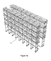
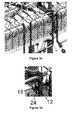
- FIG. 1a An electrical field shielding assembly 10 according to an embodiment of the invention is shown in Figures 1a , 1b and 1c .
- the electrical field shielding assembly 10 comprises a plurality of electrical conductive, shielding elements 12, and a base 14.
- VSC sub-modules 16 are housed inside the electrical field shielding assembly 10 and supported by the base 14.
- each shielding element 12 is arranged around the VSC sub-modules 16 in order to distribute electrical field lines surrounding the VSC sub-modules 16 during its operation.
- the arrangement of the plurality of shielding elements 12 around the VSC sub-modules 16 may vary depending on the shape and electrical characteristics of the VSC sub-modules 16.
- the electrical field shielding assembly 10 further includes a plurality of first hinge members 18.
- Each first hinge member 18 includes a locking portion 20 and a pivot portion 22, as shown in Figure 2a .
- the locking portion 20 defines a first rod portion with a square cross-section
- the pivot portion 22 defines a second rod portion with a circular cross-section, i.e. a cylinder.
- the locking and pivot portions 20,22 are coaxially aligned and connected end-to-end so as to define a unitary rod.
- Each shielding element 12 includes a second hinge member 24.
- Each second hinge member 24 includes a tubular portion 26, which defines an aperture 28 with a square cross-section.
- the second hinge member 24 of each of the plurality of shielding elements 12 is coupled with a respective one of the first hinge members 18 to define a hinge, as shown in Figures 2b and 2c .
- the tubular portion 26 of the second hinge member 24 encloses the first hinge member 18.
- the length of the tubular portion 26 is sized so that the second hinge member 24 is selectively slidable 30 along the axes of the locking and pivot portions 20,22 between a locked position in which the tubular portion 26 of the second hinge member 24 encloses the locking portion 20, and a pivot position in which the tubular portion 26 of the second hinge member 24 encloses the pivot portion 22.
- the aperture 28 of the tubular portion 26 is sized to fit around the square cross-section of the locking portion 20 so as to inhibit rotation of the second hinge member 24 relative to the first hinge member 18 when the second hinge member 24 is in the locked position. This ensures that the locking portion 20 is lockably retained within the tubular portion 26 when the second hinge member 24 is in the locked position.
- the aperture 28 of the tubular portion 26 is also sized to be wider than the circular cross-section of the pivot portion 22 so as to permit rotation of the second hinge member 24 relative to the first hinge member 18, i.e. rotation of the second hinge member 24 about the axes of the locking and pivot portions 20,22, when the second hinge member 24 is in the pivot position.
- each shielding element 12 is hingably mounted on the electrical field shielding assembly 10, which allows hinged movement of the corresponding shielding element 12 relative to the electrical field shielding assembly 10.
- first and second hinge members 18,24 may vary in order to rotatably couple the second hinge member 24 and the pivot portion 22 when the second hinge member 24 is in the pivot position, and lockably couple the second hinge member 24 and the locking portion 20 when the second hinge member 24 is in the locked position.
- the locking portion 20 may have a different non-cylindrical shape.
- Each first hinge member 18 further includes a stopping portion 32.
- the stopping portion 32 is attached to an axial end of the pivot portion 22 away from the locking portion 20, and extends at a right angle relative to the axes of the locking and pivot portions 20,22.
- the stopping portion 32 defines a first abutment surface 34 that engages the second hinge member 24 when the second hinge member 24 is in the pivot position and rotated relative to the first hinge member 18.
- the engagement between the first abutment surface 34 and the second hinge member 24 keeps the second hinge member 24 in coupling with the pivot portion 22. This prevents the second hinge member 24 from being detached from the first hinge member 18 during rotation of the second hinge member 24 relative to the first hinge member 18.
- the electrical field shielding assembly 10 further includes a plurality of support members 36.
- Each support member 36 is hingably connected to a respective one of the shielding elements 12.
- each support member is attached to the locking portion 20 of a respective one of the first hinge members 18, and extends at a right angle relative to the axes of the locking and pivot portions 20,22.
- Each support member 36 includes a groove 38 that encloses a circular guide element 40 of the base 14 of the electrical field shielding assembly 10 to define a sliding connection, in which the circular guide element 40 is slidable within the groove 38 from one end of the groove 38 to the other end. This allows each support member 36 to be selectively moved, in use, between a retracted position 42 towards the base 14 of the electrical field shielding assembly 10 and an extended position 44 away from the base 14 of the electrical field shielding assembly 10.
- each support member 36 When each support member 36 is in the retracted position 42, the corresponding shielding element 12 is kept in a designated position, i.e. a closed position, within the electrical field shielding assembly 10 to distribute electrical field lines surrounding the VSC sub-modules 16 during its operation.
- a clearance gap is formed between the corresponding shielding element 12 and the base 14. This not only reduces the risk of each shielding element 12 colliding with other parts of the electrical field shielding assembly 10 during its rotation, but also allows each second hinge member 24 to have a wider angle of rotation relative to the corresponding first hinge member 18.
- each first hinge member 18 is oriented such that its pivot portion 22 is located on top of its locking portion 20.
- each support member 36 defines a second abutment surface 46, which engages the corresponding shielding element 12 to limit the angle of rotation of the second hinge member 24 relative to the first hinge member 18, and thereby limit a maximum hinged movement range of the corresponding shielding element 12 relative to the electrical field shielding assembly 10.
- Either side of the support member 36 may define the second abutment surface 46 depending on the direction of rotation of the second hinge member 24 relative to the first hinge member 18.
- first and second hinge members 18,24 to hingably mount the plurality of shielding elements 12 on the electrical field shielding assembly 10 allows each shielding element 12 to be hingably moved to create an access opening in the electrical field shielding assembly 10, in order to access the VSC sub-modules 16 for the purposes of maintenance and/or repair. It will be appreciated that access to the VSC sub-modules 16 may be required for reasons other than maintenance and/or repair of the VSC sub-modules 16.
- each second hinge member 24 is in its locked position and each support member 36 is in its retracted position 42, as shown in Figures 3a to 3d .
- the coupling between each second hinge member 24 and the corresponding locking portion 20 of the first hinge member 18 ensures that the second hinge member 24 is inhibited from rotating relative to the first hinge member 18.
- the faceted edges of each locking portion 20 ensures that the corresponding shielding element 12 is aligned in parallel with the VSC sub-modules 16. In this manner each shielding element 12 is kept in a designated position, i.e. a closed position, within the electrical field shielding assembly 10 to distribute electrical field lines surrounding the VSC sub-modules 16 during their operation.
- VSC sub-modules 16 In order to maintain and/or repair one or more VSC sub-modules 16, access to the VSC sub-modules 16 is required.
- a shielding element 12 which surrounds the or each VSC sub-module 16 to be maintained or repaired, is selected. It will be appreciated that a plurality of shielding elements 12, instead of a single shielding element, may be selected in order to access the VSC sub-modules 16.
- the support member 36 that corresponds to the shielding element 12 is then slid to its extended position 44 to form a clearance gap between the shielding element 12 and the electrical field shielding assembly 10, as shown in Figures 4a to 4c .
- the second hinge member 24 of the shielding element 12 is then slid along the axes of the locking and pivot portions 20,22 from its locked position to its pivot position, as shown in Figures 5a to 5c .
- the second hinge member 24 is rotated relative to the first hinge member 18, as shown in Figures 6a to 6c .
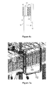
- Rotation of the second hinge member 24 is carried out, until the shielding element 12 engages the second abutment surface 46 of the support member 36, as shown in Figures 7a and 7b .
- the shielding element 12 is hingably moved to an open position, in which an access opening in the electrical field shielding assembly 10 is created, to thereby enable a user to access the VSC sub-modules 16 for the purposes of maintenance and/or repair.
- the first abutment surface 34 of the stopping portion 32 engages the second hinge member 24 so as to prevent the second hinge member 24 from being detached from the first hinge member 18.
- the second hinge member 24 is rotated relative to the first hinge member 18 until the shielding element 12 is aligned in parallel with the VSC sub-modules 16.
- the second hinge member 24 is then slid along the axes of the locking and pivot portions 20,22 from its pivot position to its locked position.
- the support member 36 is slid to its retracted position 42 so as to close the access opening and return the shielding element 12 to its designated position, i.e. the closed position, for distributing electrical field lines surrounding the VSC sub-modules 16 during their operation.
- the VSC sub-modules 16 is then turned on to resume normal operation.
- the provision of the shielding elements 12 that is hingably mounted on the electrical field shielding assembly 10 therefore results in an electrical field shielding assembly 10 with a plurality of shielding elements 12, each of which is selectively movable to provide access to the VSC sub-modules 16 housed, in use, inside the electrical field shielding assembly 10.
- the provision of the shielding elements 12 that is hingably mounted on the electrical field shielding assembly 10 also allows each of the plurality of shielding elements 12 to be secured to the electrical field shielding assembly 10 at all times, and thereby prevents each shielding element 12 from being accidentally dropped when being moved to create an access opening in the electrical field shielding assembly 10. This is particularly advantageous in tall electrical field shielding assemblies with large and heavy shielding elements 12 that are positioned at a high location relative to the ground. Damage to the shielding elements 12 is undesirable, since a change in shape of the shielding elements 12 may lead to redistribution of the electrical field lines that results in high electrical stress about the VSC sub-modules 16.
- one or more shielding elements may be hingably mounted on the electrical field shielding assembly in a different manner to that shown in the above embodiment, in order to permit hinged movement of the or each shielding element relative to the electrical field shielding assembly to create an access opening in the electrical field shielding assembly.
Landscapes
- Engineering & Computer Science (AREA)
- Power Engineering (AREA)
- Physics & Mathematics (AREA)
- Plasma & Fusion (AREA)
- Shielding Devices Or Components To Electric Or Magnetic Fields (AREA)
Abstract
Description
- This invention relates to an electrical field shielding assembly.
- The application of an electrical potential difference between a conductor and some other object results in the creation of an electrical field about the conductor. The existence of this electrical field can lead to electrical breakdown. This is problematic when the conductor is a piece of electrical equipment, and particularly problematic when the conductor is a piece of high voltage electrical equipment.
- Electrical breakdown occurs when the dielectric strength of the medium surrounding a conductor is exceeded. Partial breakdown initially occurs when the medium surrounding the conductor ionizes, forming a plasma, and permits the conduction of an electric current. As a result corona discharge occurs in the immediate vicinity of the conductor, which can be observed in the form of electromagnetic radiation, audible noise or gaseous contaminants such as ozone. If the electrical stress is high enough, complete breakdown occurs, resulting in sparking or arcing from the conductor. The electrical discharge caused by either full or partial breakdown results in damage to, or the failure of, the electrical equipment.
- Edges and pointed features of a conductor are considered critical regions that are particularly prone to electrical breakdown because the electrical stress tends to be higher in the immediate vicinity of these regions.
- The problems associated with electrical discharge from electrical equipment are often resolved by shielding the electrical equipment with an electrical field shielding assembly i.e. a corona shield. The purpose of a corona shield is to redistribute the electrical field lines surrounding the electrical equipment across a surface of relatively large curvature, particularly in the vicinity of critical regions including edges and pointed features. This reduces the electrical stress about the electrical equipment and therefore reduces the risk of electrical breakdown.
- According to an aspect of the invention, there is provided an electrical field shielding assembly comprising at least one electrically conductive, shielding element that is hingably mounted on the electrical field shielding assembly, wherein the or each shielding element is hingably movable between an open position in which an access opening in the electrical field shielding assembly is created and a closed position in which the access opening in the electrical field shielding assembly is closed.
- In use, electrical equipment is housed inside the electrical field shielding assembly. In particular, the or each shielding element is arranged around the electrical equipment in order to distribute electrical field lines surrounding the electrical equipment during its operation.
- It is important to be able to access the electrical equipment to carry out maintenance and repair. For example, when the electrical equipment is a voltage source converter (VSC), access to the VSC may be required in order to remove and replace sub-modules of the VSC. This is achieved by moving the or each shielding element in order to create an access opening in the electrical field shielding assembly that is large enough for a user to access the electrical equipment.
- Hingably mounting the or each shielding element on the electrical field shielding assembly permits hinged movement of the or each shielding element relative to the electrical field shielding assembly in order to create an access opening in the electrical field shielding assembly.
- When the or each shielding element is hingably moved to create an access opening in the electrical field shielding assembly, the or each shielding element remains secured to the electrical field shielding assembly. This prevents the or each shielding element from being accidentally dropped, which may cause damage to itself or other components in the vicinity of the electrical field shielding assembly. This is particularly advantageous in tall electrical field shielding assemblies with large and heavy shielding elements that are positioned at a high location relative to the ground. Damage to the or each shielding element is undesirable, since a change in shape of the or each shielding element may lead to a redistribution of the electrical field lines that results in high electrical stress about the electrical equipment. Hingably mounting the or each shielding element on the electrical field shielding assembly therefore reduces the risk of damage to the or each shielding element during maintenance and repair of the electrical equipment.
- In contrast, fasteners, such as bolts, are conventionally used to releasably secure a shielding element to an electrical field shielding assembly. The use of such fasteners not only requires physical handling of the or each shielding element, but also requires the shielding element to be completely detached from the electrical field shielding assembly in order to create an opening for access to the electrical equipment. As such, there is a risk that the shielding element and the fastener(s) may be accidentally dropped during maintenance and repair of the electrical equipment.
- The provision of at least one electrically conductive, shielding element that is hingably mounted on the electrical field shielding assembly therefore results in an electrical field shielding assembly with at least one shielding element that is movable to provide access to electrical equipment housed, in use, inside the electrical field shielding assembly, whilst being secured to the electrical field shielding assembly at all times.
- The or each shielding element may be shaped and/or arranged in different ways depending on the shielding requirements of the electrical field shielding assembly. For example, the or each shielding element is shaped and/or arranged to form at least part of a hollow enclosure when in the closed position.
- The or each shielding element may be hingably mounted on the electrical field shielding assembly in different ways in order to permit hinged movement of the or each shielding element relative to the electrical field shielding assembly to create an access opening in the electrical field shielding assembly.
- In embodiments of the invention, the electrical field shielding assembly may include at least one first hinge member, wherein the or each shielding element includes a second hinge member, the or each second hinge member being hingably coupled with the first hinge member or a respective one of the first hinge members. In such embodiments, the or each first hinge member may include:
- a locking portion to inhibit rotation of the corresponding second hinge member relative to the first hinge member, and
- a pivot portion to permit rotation of the corresponding second hinge member relative to the first hinge member;
- In order to arrange the or each shielding element around the electrical equipment, the second hinge member of the or each shielding element is moved to a locked position. When the second hinge member is in the locked position, the coupling between the second hinge member and the locking portion prevents rotation of the second hinge member relative to the first hinge member. This allows the or each shielding element to maintain its position relative to the electrical equipment in order to ensure proper distribution of the electrical field lines during operation of the electrical equipment.
- In order to create the opening, the second hinge member of the or each shielding element is moved to a pivot position. When the second hinge member is in the pivot position, the coupling between the second hinge member and the locking portion permits rotation of the second hinge member relative to the first hinge member. This allows the or each shielding element to be hingably moved to create the opening in the electrical field shielding assembly.
- The shape of the pivot and locking portions of the or each first hinge member may vary to carry out their respective function. For example, the or each pivot portion may be cylindrical, so as to permit rotation of the second hinge member relative to the first hinge member, and/or the or each locking portion may be non-cylindrical, so as to inhibit rotation of the second hinge member relative to the first hinge member.
- When the or each locking portion is non-cylindrical, the or each locking portion may include at least one faceted edge. The orientation of the or each faceted edge may be directed to position the or each shielding element so as to define a specific shape of the electrical field shielding assembly. For example, the or each shielding element may be kept in parallel with the electrical equipment housed within the electrical field shielding assembly.
- The shape and configuration of the first and second hinge members may vary in order to rotatably couple the second hinge member and the corresponding pivot portion when the or each second hinge member is in the pivot position, and lockably couple the second hinge member and the corresponding locking portion when the or each second hinge member is in the locked position.
- For example, in embodiments of the invention employing the use of first and second hinge members, the or each second hinge member may include a tubular portion that encloses the corresponding first hinge member. In such embodiments wherein the or each second hinge member includes a tubular portion, the tubular portion of the or each second hinge member may be slidably coupled with the corresponding first hinge member.
- In embodiments employing the use of the or each second hinge member with a tubular portion, the first and second hinge members may be shaped to define a gap between the tubular portion and the pivot portion when the second hinge member is in the pivot position, the gap being sized to permit rotation of the second hinge member relative to the first hinge member.
- In further embodiments employing the use of the or each second hinge member with a tubular portion, the first and second hinge members may be shaped to keep the locking portion lockably retained within the tubular portion when the second hinge member is in the locked position.
- Preferably the or each first hinge member further includes a stopping portion with a first abutment surface to engage the corresponding second hinge member so as to keep the corresponding second hinge member in coupling with the pivot portion when the second hinge member is in the pivot position.
- The inclusion of a stopping portion in the or each first hinge member prevents the corresponding second hinge member from being detached from the first hinge member when the second hinge member is rotating relative to the first hinge member.
- In embodiments of the invention, the electrical field shielding assembly may further include at least one support member, the or each shielding element being hingably connected to the support member or a respective one of the support members, the or each support member being movably connected to the electrical field shielding assembly, wherein the or each support member is selectively movable between a retracted position towards the electrical field shielding assembly and an extended position away from the electrical field shielding assembly. In such embodiments, the or each support member may be slidably connected to the electrical field shielding assembly.
- The inclusion of at least one support member in the electrical field shielding assembly allows formation of a clearance gap between a shielding element and the rest of the electrical field shielding assembly before the shielding element is hingably moved to the open position in which the access opening in the electrical field shielding assembly is created. This not only reduces the risk of the shielding element colliding with other parts of the electrical field shielding assembly during its rotation, but also allows the shielding element to have a wider hinged movement range to create a larger access opening in the electrical field shielding assembly.
- In addition, the use of at least one support member in the electrical field shielding assembly allows the or each shielding element to be kept close to the electrical equipment by moving the or each support member to its retracted position, without restricting the maximum hinged movement range of the or each shielding element when the or each support member is in its extended position.
- In further embodiments of the invention, the electrical field shielding assembly may further include at least one second abutment surface to engage the or each shielding element so as to limit a maximum hinged movement range of the or each shielding element relative to the electrical field shielding assembly. In such embodiments employing the use of at least one second abutment surface and at least one support member, the or each support member may define the second abutment surface or a respective one of the second abutment surfaces.
- The configuration of the electrical field shielding assembly in this manner prevents collision between the or each shielding element and other parts of the electrical field shielding assembly as a result of over-movement of the or each shielding element.
- A preferred embodiment of the invention will now be described, by way of a non-limiting example, with reference to the accompanying drawings in which:
-
Figure 1a shows an electrical field shielding assembly according to an embodiment of the invention; -
Figures 1b and1c show close-up views of part of the electrical field shielding assembly ofFigure 1a ; -
Figure 2a shows a first hinge member that forms part of the electrical field shielding assembly ofFigure 1a ; -
Figure 2b shows a shielding element with a second hinge member that is hingably coupled to the first hinge member ofFigure 2a ; -
Figure 2c shows a cross-sectional view of the first and second hinge members along lines A-A' ofFigure 2b ; -
Figures 3a and 3b show a configuration of the electrical field shielding assembly ofFigure 1 a when the second hinge member is in a locked position and a support member is in a retracted position; -
Figure 3c shows a configuration of the first and second hinge members ofFigures 3a and 3b ; -
Figure 3d shows a cross-sectional view of the first and second hinge members along lines A-A' ofFigure 3c ; -
Figures 4a and 4b show a configuration of the electrical field shielding assembly ofFigure 1 a when the second hinge member is in the locked position and the support member is in an extended position; -
Figure 4c shows a configuration of the first and second hinge members ofFigures 4a and 4b ; -
Figure 5a shows a configuration of the electrical field shielding assembly ofFigure 1 a when the second hinge member is in a pivot position and the support member is in the extended position; -
Figure 5b shows a configuration of the first and second hinge members ofFigure 5a ; -
Figure 5c shows a cross-sectional view of the first and second hinge members along lines A-A' ofFigure 5b ; -
Figure 6a shows a configuration of the electrical field shielding assembly ofFigure 1a when the second hinge member is rotated relative to the first hinge member to create an access opening in the electrical field shielding assembly; -
Figure 6b shows a configuration of the first and second hinge members ofFigure 6a ; -
Figure 6c shows a cross-sectional view of the first and second hinge members along lines A-A' ofFigure 6b ; -
Figure 7a shows a configuration of the electrical field shielding assembly ofFigure 1 a when the shielding element engages a second abutment surface of the support member; and -
Figure 7b shows a configuration of the first and second hinge members ofFigure 7a . - An electrical
field shielding assembly 10 according to an embodiment of the invention is shown inFigures 1a ,1b and1c . - The electrical
field shielding assembly 10 comprises a plurality of electrical conductive, shieldingelements 12, and abase 14. - In use, voltage source converter (VSC) sub-modules 16 are housed inside the electrical
field shielding assembly 10 and supported by thebase 14. In particular, each shieldingelement 12 is arranged around the VSC sub-modules 16 in order to distribute electrical field lines surrounding the VSC sub-modules 16 during its operation. - The arrangement of the plurality of shielding
elements 12 around the VSC sub-modules 16 may vary depending on the shape and electrical characteristics of theVSC sub-modules 16. - It is envisaged that, in use, other types of electrical equipment may be housed inside the electrical
field shielding assembly 10. - The electrical
field shielding assembly 10 further includes a plurality offirst hinge members 18. Eachfirst hinge member 18 includes a lockingportion 20 and apivot portion 22, as shown inFigure 2a . The lockingportion 20 defines a first rod portion with a square cross-section, while thepivot portion 22 defines a second rod portion with a circular cross-section, i.e. a cylinder. The locking andpivot portions - Each shielding
element 12 includes asecond hinge member 24. Eachsecond hinge member 24 includes atubular portion 26, which defines anaperture 28 with a square cross-section. - The
second hinge member 24 of each of the plurality of shieldingelements 12 is coupled with a respective one of thefirst hinge members 18 to define a hinge, as shown inFigures 2b and 2c . To define the hinge, thetubular portion 26 of thesecond hinge member 24 encloses thefirst hinge member 18. The length of thetubular portion 26 is sized so that thesecond hinge member 24 is selectively slidable 30 along the axes of the locking andpivot portions tubular portion 26 of thesecond hinge member 24 encloses the lockingportion 20, and a pivot position in which thetubular portion 26 of thesecond hinge member 24 encloses thepivot portion 22. - The
aperture 28 of thetubular portion 26 is sized to fit around the square cross-section of the lockingportion 20 so as to inhibit rotation of thesecond hinge member 24 relative to thefirst hinge member 18 when thesecond hinge member 24 is in the locked position. This ensures that the lockingportion 20 is lockably retained within thetubular portion 26 when thesecond hinge member 24 is in the locked position. - The
aperture 28 of thetubular portion 26 is also sized to be wider than the circular cross-section of thepivot portion 22 so as to permit rotation of thesecond hinge member 24 relative to thefirst hinge member 18, i.e. rotation of thesecond hinge member 24 about the axes of the locking andpivot portions second hinge member 24 is in the pivot position. - In this manner, each shielding
element 12 is hingably mounted on the electricalfield shielding assembly 10, which allows hinged movement of thecorresponding shielding element 12 relative to the electricalfield shielding assembly 10. - It is envisaged that, in other embodiments, the shape and configuration of the first and
second hinge members second hinge member 24 and thepivot portion 22 when thesecond hinge member 24 is in the pivot position, and lockably couple thesecond hinge member 24 and the lockingportion 20 when thesecond hinge member 24 is in the locked position. For example, the lockingportion 20 may have a different non-cylindrical shape. - Each
first hinge member 18 further includes a stoppingportion 32. The stoppingportion 32 is attached to an axial end of thepivot portion 22 away from the lockingportion 20, and extends at a right angle relative to the axes of the locking andpivot portions portion 32 defines afirst abutment surface 34 that engages thesecond hinge member 24 when thesecond hinge member 24 is in the pivot position and rotated relative to thefirst hinge member 18. The engagement between thefirst abutment surface 34 and thesecond hinge member 24 keeps thesecond hinge member 24 in coupling with thepivot portion 22. This prevents thesecond hinge member 24 from being detached from thefirst hinge member 18 during rotation of thesecond hinge member 24 relative to thefirst hinge member 18. - The electrical
field shielding assembly 10 further includes a plurality ofsupport members 36. Eachsupport member 36 is hingably connected to a respective one of the shieldingelements 12. In particular, each support member is attached to the lockingportion 20 of a respective one of thefirst hinge members 18, and extends at a right angle relative to the axes of the locking andpivot portions support member 36 includes agroove 38 that encloses acircular guide element 40 of thebase 14 of the electricalfield shielding assembly 10 to define a sliding connection, in which thecircular guide element 40 is slidable within thegroove 38 from one end of thegroove 38 to the other end. This allows eachsupport member 36 to be selectively moved, in use, between a retractedposition 42 towards thebase 14 of the electricalfield shielding assembly 10 and anextended position 44 away from thebase 14 of the electricalfield shielding assembly 10. - When each
support member 36 is in the retractedposition 42, the corresponding shieldingelement 12 is kept in a designated position, i.e. a closed position, within the electricalfield shielding assembly 10 to distribute electrical field lines surrounding the VSC sub-modules 16 during its operation. When eachsupport member 36 is in theextended position 44, a clearance gap is formed between thecorresponding shielding element 12 and thebase 14. This not only reduces the risk of each shieldingelement 12 colliding with other parts of the electricalfield shielding assembly 10 during its rotation, but also allows eachsecond hinge member 24 to have a wider angle of rotation relative to the correspondingfirst hinge member 18. - When each
support member 36 is connected to thebase 14 of the electricalfield shielding assembly 10, eachfirst hinge member 18 is oriented such that itspivot portion 22 is located on top of its lockingportion 20. - A side of each
support member 36 defines asecond abutment surface 46, which engages the corresponding shieldingelement 12 to limit the angle of rotation of thesecond hinge member 24 relative to thefirst hinge member 18, and thereby limit a maximum hinged movement range of thecorresponding shielding element 12 relative to the electricalfield shielding assembly 10. Either side of thesupport member 36 may define thesecond abutment surface 46 depending on the direction of rotation of thesecond hinge member 24 relative to thefirst hinge member 18. - The use of the first and
second hinge members elements 12 on the electricalfield shielding assembly 10 allows each shieldingelement 12 to be hingably moved to create an access opening in the electricalfield shielding assembly 10, in order to access the VSC sub-modules 16 for the purposes of maintenance and/or repair. It will be appreciated that access to the VSC sub-modules 16 may be required for reasons other than maintenance and/or repair of theVSC sub-modules 16. - Operation of the first and
second hinge members field shielding assembly 10 is described as follows, with reference toFigures 3a to 7b . - During normal operation of the
VSC sub-modules 16, eachsecond hinge member 24 is in its locked position and eachsupport member 36 is in its retractedposition 42, as shown inFigures 3a to 3d . The coupling between eachsecond hinge member 24 and the corresponding lockingportion 20 of thefirst hinge member 18 ensures that thesecond hinge member 24 is inhibited from rotating relative to thefirst hinge member 18. The faceted edges of each lockingportion 20 ensures that the corresponding shieldingelement 12 is aligned in parallel with theVSC sub-modules 16. In this manner each shieldingelement 12 is kept in a designated position, i.e. a closed position, within the electricalfield shielding assembly 10 to distribute electrical field lines surrounding the VSC sub-modules 16 during their operation. - In order to maintain and/or repair one or
more VSC sub-modules 16, access to theVSC sub-modules 16 is required. - After turning off the
VSC sub-modules 16, a shieldingelement 12, which surrounds the or each VSC sub-module 16 to be maintained or repaired, is selected. It will be appreciated that a plurality of shieldingelements 12, instead of a single shielding element, may be selected in order to access theVSC sub-modules 16. Thesupport member 36 that corresponds to the shieldingelement 12 is then slid to itsextended position 44 to form a clearance gap between the shieldingelement 12 and the electricalfield shielding assembly 10, as shown inFigures 4a to 4c . Thesecond hinge member 24 of the shieldingelement 12 is then slid along the axes of the locking andpivot portions Figures 5a to 5c . - Once the
second hinge member 24 is in its pivot position, thesecond hinge member 24 is rotated relative to thefirst hinge member 18, as shown inFigures 6a to 6c . Rotation of thesecond hinge member 24 is carried out, until the shieldingelement 12 engages thesecond abutment surface 46 of thesupport member 36, as shown inFigures 7a and7b . In this manner the shieldingelement 12 is hingably moved to an open position, in which an access opening in the electricalfield shielding assembly 10 is created, to thereby enable a user to access the VSC sub-modules 16 for the purposes of maintenance and/or repair. - Meanwhile, when the
second hinge member 24 is in its pivot position, thefirst abutment surface 34 of the stoppingportion 32 engages thesecond hinge member 24 so as to prevent thesecond hinge member 24 from being detached from thefirst hinge member 18. - After maintenance and/or repair of the
VSC sub-modules 16 is completed and access to theVSC sub-modules 16 is no longer required, thesecond hinge member 24 is rotated relative to thefirst hinge member 18 until the shieldingelement 12 is aligned in parallel with theVSC sub-modules 16. Thesecond hinge member 24 is then slid along the axes of the locking andpivot portions portion 20 is lockably retained inside thetubular portion 26 of thesecond hinge member 24, thesupport member 36 is slid to its retractedposition 42 so as to close the access opening and return the shieldingelement 12 to its designated position, i.e. the closed position, for distributing electrical field lines surrounding the VSC sub-modules 16 during their operation. The VSC sub-modules 16 is then turned on to resume normal operation. - The provision of the shielding
elements 12 that is hingably mounted on the electricalfield shielding assembly 10 therefore results in an electricalfield shielding assembly 10 with a plurality of shieldingelements 12, each of which is selectively movable to provide access to the VSC sub-modules 16 housed, in use, inside the electricalfield shielding assembly 10. - The provision of the shielding
elements 12 that is hingably mounted on the electricalfield shielding assembly 10 also allows each of the plurality of shieldingelements 12 to be secured to the electricalfield shielding assembly 10 at all times, and thereby prevents each shieldingelement 12 from being accidentally dropped when being moved to create an access opening in the electricalfield shielding assembly 10. This is particularly advantageous in tall electrical field shielding assemblies with large andheavy shielding elements 12 that are positioned at a high location relative to the ground. Damage to theshielding elements 12 is undesirable, since a change in shape of the shieldingelements 12 may lead to redistribution of the electrical field lines that results in high electrical stress about theVSC sub-modules 16. - It is envisaged that, in other embodiments of the invention, one or more shielding elements may be hingably mounted on the electrical field shielding assembly in a different manner to that shown in the above embodiment, in order to permit hinged movement of the or each shielding element relative to the electrical field shielding assembly to create an access opening in the electrical field shielding assembly.
Claims (15)
- An electrical field shielding assembly comprising at least one electrically conductive, shielding element that is hingably mounted on the electrical field shielding assembly, wherein the or each shielding element is hingably movable between an open position in which an access opening in the electrical field shielding assembly is created and a closed position in which the access opening in the electrical field shielding assembly is closed.
- An electrical field shielding assembly according to Claim 1 wherein the or each shielding element is shaped and/or arranged to form at least part of a hollow enclosure when in the closed position.
- An electrical field shielding assembly according to any preceding claim including at least one first hinge member, wherein the or each shielding element includes a second hinge member, the or each second hinge member being hingably coupled with the first hinge member or a respective one of the first hinge members.
- An electrical field shielding assembly according to Claim 3, wherein the or each first hinge member includes:a locking portion to inhibit rotation of the corresponding second hinge member relative to the first hinge member, anda pivot portion to permit rotation of the corresponding second hinge member relative to the first hinge member;wherein the or each second hinge member is selectively movable between a locked position in which the or each second hinge member is lockably coupled with the corresponding locking portion, and a pivot position in which the or each second hinge member is rotatably coupled with the corresponding pivot portion.
- An electrical field shielding assembly according to Claim 4 wherein the or each pivot portion is cylindrical.
- An electrical field shielding assembly according to Claim 4 or Claim 5 wherein the or each locking portion is non-cylindrical.
- An electrical field shielding assembly according to Claim 6 wherein the or each locking portion includes at least one faceted edge.
- An electrical field shielding assembly according to any of Claims 4 to 7 wherein the or each second hinge member includes a tubular portion that encloses the corresponding first hinge member.
- An electrical field shielding assembly according to Claim 8 wherein the tubular portion of the or each second hinge member is slidably coupled with the corresponding first hinge member.
- An electrical field shielding assembly according to Claim 8 or Claim 9 wherein the first and second hinge members are shaped to define a gap between the tubular portion and the pivot portion when the second hinge member is in the pivot position, the gap being sized to permit rotation of the second hinge member relative to the first hinge member.
- An electrical field shielding assembly according to any of Claims 8 to 10 wherein the first and second hinge members are shaped to keep the locking portion lockably retained within the tubular portion when the second hinge member is in the locked position.
- An electrical field shielding assembly according to any of Claims 4 to 11 wherein the or each first hinge member further includes a stopping portion with a first abutment surface to engage the corresponding second hinge member so as to keep the corresponding second hinge member in coupling with the pivot portion when the second hinge member is in the pivot position.
- An electrical field shielding assembly according to any preceding claim further including at least one support member, the or each shielding element being hingably connected to the support member or a respective one of the support members, the or each support member being movably connected to the electrical field shielding assembly, wherein the or each support member is selectively movable between a retracted position towards the electrical field shielding assembly and an extended position away from the electrical field shielding assembly.
- An electrical field shielding assembly according to any preceding claim further including at least one second abutment surface to engage the or each shielding element to limit a maximum hinged movement range of the or each shielding element relative to the electrical field shielding assembly.
- An electrical field shielding assembly according to Claim 14 when dependent from Claim 13, wherein the or each support member defines the second abutment surface or a respective one of the second abutment surfaces.
Priority Applications (4)
| Application Number | Priority Date | Filing Date | Title |
|---|---|---|---|
| EP20120275077 EP2667468A1 (en) | 2012-05-24 | 2012-05-24 | Shielding assembly |
| CN201380039227.0A CN104488152B (en) | 2012-05-24 | 2013-05-23 | Shielding assembly |
| PCT/EP2013/060655 WO2013174939A1 (en) | 2012-05-24 | 2013-05-23 | Shielding assembly |
| US14/402,631 US9667038B2 (en) | 2012-05-24 | 2013-05-23 | Shielding assembly |
Applications Claiming Priority (1)
| Application Number | Priority Date | Filing Date | Title |
|---|---|---|---|
| EP20120275077 EP2667468A1 (en) | 2012-05-24 | 2012-05-24 | Shielding assembly |
Publications (1)
| Publication Number | Publication Date |
|---|---|
| EP2667468A1 true EP2667468A1 (en) | 2013-11-27 |
Family
ID=48570089
Family Applications (1)
| Application Number | Title | Priority Date | Filing Date |
|---|---|---|---|
| EP20120275077 Withdrawn EP2667468A1 (en) | 2012-05-24 | 2012-05-24 | Shielding assembly |
Country Status (4)
| Country | Link |
|---|---|
| US (1) | US9667038B2 (en) |
| EP (1) | EP2667468A1 (en) |
| CN (1) | CN104488152B (en) |
| WO (1) | WO2013174939A1 (en) |
Cited By (3)
| Publication number | Priority date | Publication date | Assignee | Title |
|---|---|---|---|---|
| WO2015086210A1 (en) * | 2013-12-10 | 2015-06-18 | Alstom Technology Ltd | Valve module installation method |
| JPWO2020017033A1 (en) * | 2018-07-20 | 2021-01-07 | 東芝三菱電機産業システム株式会社 | Power converter |
| WO2025203158A1 (en) * | 2024-03-25 | 2025-10-02 | 株式会社Tmeic | Power conversion device and brace for power conversion device |
Citations (3)
| Publication number | Priority date | Publication date | Assignee | Title |
|---|---|---|---|---|
| US2242092A (en) * | 1939-04-19 | 1941-05-13 | Line Material Co | Switch construction |
| US3530264A (en) * | 1969-05-09 | 1970-09-22 | Ite Imperial Corp | Vertical reach disconnect switch |
| US4593339A (en) * | 1984-05-07 | 1986-06-03 | Robinson Will B | Anti-static transit case |
Family Cites Families (6)
| Publication number | Priority date | Publication date | Assignee | Title |
|---|---|---|---|---|
| US3697819A (en) * | 1971-10-21 | 1972-10-10 | Gen Electric | Electric power distribution substation |
| US4697305A (en) * | 1985-02-14 | 1987-10-06 | Harold R. Wing | Release mechanism for locking hinge for multi-positioned ladder |
| KR100186355B1 (en) | 1996-06-27 | 1999-05-15 | 이종수 | Contacting point control apparatus of three-position multi-circuit |
| CN1244974C (en) | 2002-07-16 | 2006-03-08 | 利塔尔两合公司 | Switch cubicle with one frame |
| DE10132979C1 (en) | 2001-07-06 | 2002-10-17 | Rittal Gmbh & Co Kg | Switchgear cabinet has double-walled panels attached to frame for increased protection against vandalism |
| EP2395616B1 (en) | 2010-06-10 | 2014-09-17 | ABB Technology AG | An apparatus for electric power distribution |
-
2012
- 2012-05-24 EP EP20120275077 patent/EP2667468A1/en not_active Withdrawn
-
2013
- 2013-05-23 WO PCT/EP2013/060655 patent/WO2013174939A1/en not_active Ceased
- 2013-05-23 CN CN201380039227.0A patent/CN104488152B/en not_active Expired - Fee Related
- 2013-05-23 US US14/402,631 patent/US9667038B2/en not_active Expired - Fee Related
Patent Citations (3)
| Publication number | Priority date | Publication date | Assignee | Title |
|---|---|---|---|---|
| US2242092A (en) * | 1939-04-19 | 1941-05-13 | Line Material Co | Switch construction |
| US3530264A (en) * | 1969-05-09 | 1970-09-22 | Ite Imperial Corp | Vertical reach disconnect switch |
| US4593339A (en) * | 1984-05-07 | 1986-06-03 | Robinson Will B | Anti-static transit case |
Cited By (4)
| Publication number | Priority date | Publication date | Assignee | Title |
|---|---|---|---|---|
| WO2015086210A1 (en) * | 2013-12-10 | 2015-06-18 | Alstom Technology Ltd | Valve module installation method |
| JPWO2020017033A1 (en) * | 2018-07-20 | 2021-01-07 | 東芝三菱電機産業システム株式会社 | Power converter |
| WO2025203158A1 (en) * | 2024-03-25 | 2025-10-02 | 株式会社Tmeic | Power conversion device and brace for power conversion device |
| JPWO2025203158A1 (en) * | 2024-03-25 | 2025-10-02 |
Also Published As
| Publication number | Publication date |
|---|---|
| US9667038B2 (en) | 2017-05-30 |
| US20150109709A1 (en) | 2015-04-23 |
| WO2013174939A1 (en) | 2013-11-28 |
| CN104488152B (en) | 2017-04-19 |
| CN104488152A (en) | 2015-04-01 |
Similar Documents
| Publication | Publication Date | Title |
|---|---|---|
| US9379502B2 (en) | Tool-less busway take-off device for electrical busway and method of installing | |
| DE112015002390B4 (en) | ARC ARRESTER CIRCUIT BREAKER AND ENERGY RECEIVING AND DISTRIBUTING EQUIPMENT USING SAME | |
| US9425588B2 (en) | Electrical enclosure and guard assembly therefor | |
| KR102152110B1 (en) | Power distribution box for underground power distribution line | |
| US9667038B2 (en) | Shielding assembly | |
| RU2592073C2 (en) | Flexible cover for contacts of inserted or slide-in unit | |
| US20170365987A1 (en) | Arc fault resistant electric equipment | |
| JP6030723B2 (en) | Support structure for charging resistance of special high voltage circuit breaker | |
| US9356435B2 (en) | Switchgear enclosure housing assembly including an extendable conductor assembly | |
| KR101405148B1 (en) | Apparatus for adjusting height of mounting bracket in lightning arrester | |
| US9620304B2 (en) | Interlock device of ring main unit | |
| US11588305B2 (en) | Distribution board ventilation system | |
| JP6434831B2 (en) | Insulation barrier for switchgear | |
| CN105048132A (en) | High voltage grounding wire apparatus | |
| US20160336680A1 (en) | Protective cover for a connector | |
| CN211281111U (en) | High tension switchgear transportation equipment | |
| JP5378333B2 (en) | Switchgear | |
| CN103594949B (en) | A kind of grounding system for high-tension switch cabinet and processing method thereof | |
| KR101587952B1 (en) | Conductor change works carriage of main bus inside substation | |
| US20170117641A1 (en) | Cable termination for connecting a switchgear assembly to a high-voltage cable | |
| KR101847207B1 (en) | Electric field prevention institutions for establishment of high-voltage electric wire | |
| KR101168536B1 (en) | High voltage switchgear having rounding shield for enhancing the dielectric stability and shield edge structure of high voltage switchgear | |
| KR20190094019A (en) | Miniature Circuit Breaker | |
| JP2018057247A (en) | Short circuit ground apparatus | |
| JP5953167B2 (en) | Switchgear |
Legal Events
| Date | Code | Title | Description |
|---|---|---|---|
| PUAI | Public reference made under article 153(3) epc to a published international application that has entered the european phase |
Free format text: ORIGINAL CODE: 0009012 |
|
| AK | Designated contracting states |
Kind code of ref document: A1 Designated state(s): AL AT BE BG CH CY CZ DE DK EE ES FI FR GB GR HR HU IE IS IT LI LT LU LV MC MK MT NL NO PL PT RO RS SE SI SK SM TR |
|
| AX | Request for extension of the european patent |
Extension state: BA ME |
|
| RIN1 | Information on inventor provided before grant (corrected) |
Inventor name: CALGOTRA, SARB Inventor name: DAVIDSON, COLIN CHARNOCK Inventor name: EVANS, MICHAEL |
|
| 17P | Request for examination filed |
Effective date: 20140527 |
|
| RBV | Designated contracting states (corrected) |
Designated state(s): AL AT BE BG CH CY CZ DE DK EE ES FI FR GB GR HR HU IE IS IT LI LT LU LV MC MK MT NL NO PL PT RO RS SE SI SK SM TR |
|
| STAA | Information on the status of an ep patent application or granted ep patent |
Free format text: STATUS: THE APPLICATION IS DEEMED TO BE WITHDRAWN |
|
| 18D | Application deemed to be withdrawn |
Effective date: 20151201 |