EP2667145A1 - Image processing device, and image processing program - Google Patents
Image processing device, and image processing program Download PDFInfo
- Publication number
- EP2667145A1 EP2667145A1 EP11860953.6A EP11860953A EP2667145A1 EP 2667145 A1 EP2667145 A1 EP 2667145A1 EP 11860953 A EP11860953 A EP 11860953A EP 2667145 A1 EP2667145 A1 EP 2667145A1
- Authority
- EP
- European Patent Office
- Prior art keywords
- image
- imaging
- captured
- measurement
- measurement result
- Prior art date
- Legal status (The legal status is an assumption and is not a legal conclusion. Google has not performed a legal analysis and makes no representation as to the accuracy of the status listed.)
- Granted
Links
Images











Classifications
-
- H—ELECTRICITY
- H04—ELECTRIC COMMUNICATION TECHNIQUE
- H04N—PICTORIAL COMMUNICATION, e.g. TELEVISION
- H04N5/00—Details of television systems
- H04N5/222—Studio circuitry; Studio devices; Studio equipment
- H04N5/262—Studio circuits, e.g. for mixing, switching-over, change of character of image, other special effects ; Cameras specially adapted for the electronic generation of special effects
- H04N5/2621—Cameras specially adapted for the electronic generation of special effects during image pickup, e.g. digital cameras, camcorders, video cameras having integrated special effects capability
-
- G—PHYSICS
- G06—COMPUTING OR CALCULATING; COUNTING
- G06T—IMAGE DATA PROCESSING OR GENERATION, IN GENERAL
- G06T3/00—Geometric image transformations in the plane of the image
- G06T3/40—Scaling of whole images or parts thereof, e.g. expanding or contracting
- G06T3/4038—Image mosaicing, e.g. composing plane images from plane sub-images
-
- G—PHYSICS
- G06—COMPUTING OR CALCULATING; COUNTING
- G06T—IMAGE DATA PROCESSING OR GENERATION, IN GENERAL
- G06T7/00—Image analysis
- G06T7/70—Determining position or orientation of objects or cameras
- G06T7/73—Determining position or orientation of objects or cameras using feature-based methods
- G06T7/74—Determining position or orientation of objects or cameras using feature-based methods involving reference images or patches
-
- G—PHYSICS
- G01—MEASURING; TESTING
- G01B—MEASURING LENGTH, THICKNESS OR SIMILAR LINEAR DIMENSIONS; MEASURING ANGLES; MEASURING AREAS; MEASURING IRREGULARITIES OF SURFACES OR CONTOURS
- G01B2210/00—Aspects not specifically covered by any group under G01B, e.g. of wheel alignment, caliper-like sensors
- G01B2210/52—Combining or merging partially overlapping images to an overall image
-
- G—PHYSICS
- G06—COMPUTING OR CALCULATING; COUNTING
- G06T—IMAGE DATA PROCESSING OR GENERATION, IN GENERAL
- G06T2207/00—Indexing scheme for image analysis or image enhancement
- G06T2207/10—Image acquisition modality
- G06T2207/10016—Video; Image sequence
-
- G—PHYSICS
- G06—COMPUTING OR CALCULATING; COUNTING
- G06T—IMAGE DATA PROCESSING OR GENERATION, IN GENERAL
- G06T2207/00—Indexing scheme for image analysis or image enhancement
- G06T2207/30—Subject of image; Context of image processing
- G06T2207/30108—Industrial image inspection
- G06T2207/30164—Workpiece; Machine component
Definitions
- the present invention relates to an image processing device and an image processing program, for being aimed at conveyer tracking.
- a working process of tracking and holding a workpiece using a moving machine (hereinafter referred to as an "industrial robot” or simply referred to as a “robot") while conveying the workpiece with a conveying device such as a belt conveyer can be cited as an application example of the image processing technology.
- the working process is called conveyer tracking.
- an imaging device captures an image of the workpiece on the conveying device, and an image processing device performs measurement processing such as pattern matching and binarization processing to the image obtained by the imaging, thereby identifying a position in which each workpiece exists.
- a robot tracks and holds each workpiece based on the identified position in which each workpiece exists.
- Patent Document 1 Japanese Unexamined Patent Publication No. 2002-113679
- the images of the plural workpieces conveyed by a conveying body are captured, and handling of the workpieces is controlled based on a position coordinate of each workpiece recognized from the imaging result.
- the images of an imaging region of imaging means and a subsequent imaging region are continuously captured within a width, into which a whole shape of the workpiece fits, while overlapping with each other in a traveling direction, and the position coordinate only of the workpiece including the whole shape in the imaging region is recognized.
- Patent Document 2 Japanese Unexamined Patent Publication No. 5-260264
- the panoramic image in the range where an operator captures the images is generated by joining plural frames, in which the operator continuously captures the images while performing panning of a camera held by hand.
- the panoramic image generated with the image processing device of Patent Document 2 is not the workpiece on the conveying device, and is not correlated with measurement information on the workpiece.
- An object of the present invention is to provide an image processing device and an image processing program, for outputting information assisting the operator to understand the state on the route through which the workpiece is conveyed using the captured image.
- an image processing device that is connected to an imaging unit, the imaging unit having an overlapping region in an imaging range before and after continuous imaging, the image processing device includes: an interface that receives plural captured images obtained by the imaging unit; measurement means for acquiring a measurement result of a subject in the captured image by performing measurement processing to the captured image; synthesis means for generating a synthesized image by synthesizing the plural captured images such that the captured images overlap with one another within an overlapping range corresponding to the overlapping region in imaging order; and output means for outputting the synthesized image, information indicating the overlapping range correlated with the synthesized image, and information indicating the measurement result.
- the output means outputs the information indicating the overlapping range and the information indicating the measurement result while superimposing on the synthesized image.
- the output means varies an output mode of each captured image in the synthesized image.
- the image processing device further includes an operation input unit that externally receives an operation.
- the output means outputs the captured image selected by the operation input unit in the synthesized image while enlarging the captured image.
- the image processing device further includes selection means for selecting the measurement result that is designated by the operation received by the operation input unit from the measurement results corresponding to the captured images.
- the output means outputs the synthesized image, the synthesized image including the captured image corresponding to the measurement result selected by the selection means and captured images captured before and after the captured image.
- the output means selects the captured image designating a value in which the corresponding measurement result is previously specified from the captured images in the synthesized image, and outputs the selected captured image.
- the output means varies the output modes of the measurement result corresponding to the captured image in which the imaging order is odd-numbered and the measurement result corresponding to the captured image in which the imaging order is even-numbered in the captured images in the synthesized image.
- the image processing device further includes means for outputting information on a time necessary for the measurement processing performed by the measurement means.
- the information on the necessary time is a ratio of the time necessary for the captured image measurement processing to a time interval before and after the continuous imaging.
- the ratio is acquired with respect to each captured image of the synthesized image, and the ratio is output while correlated with the synthesized image and each captured image of the synthesized image.
- an image processing program that is executed by a computer connected to an imaging unit is provided, the imaging unit having an overlapping region in an imaging range before and after continuous imaging.
- the image processing program causes the computer to act as: an interface that receives plural captured images obtained by the imaging unit; measurement means for acquiring a measurement result of a subject in the captured image by performing measurement processing to the captured image; synthesis means for generating a synthesized image by synthesizing the plurality of captured images such that the captured images overlap with one another within an overlapping range corresponding to the overlapping region in imaging order; and output means for outputting the synthesized image, information indicating the overlapping range correlated with the synthesized image, and information indicating the measurement result.
- the operator can acquire the information understanding a state on the route through which the workpiece is conveyed.
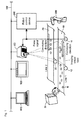
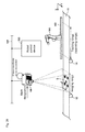
- Fig. 1 is a schematic diagram illustrating a configuration of a conveyer tracking system in which a visual sensor according to a first embodiment of the present invention is used.
- the conveyer tracking system in Fig. 1 includes two conveying devices (conveyers) 10 and 20.
- the conveyers 10 and 20 are rotated by driving rollers 12 and 22, respectively.
- the conveyers 10 and 20 are also referred to as a line 1 and a line 2.
- the line 1 moves to a right side
- the line 2 moves to a left side.
- a discharging device 30 or the like randomly supplies a workpiece W to the line 1 from the left side.
- the workpiece W on the line 1 moves from the left to the right.
- foods such as a sweet stuff or various tablets are considered as the workpiece W.
- a visual sensor 100 of the first embodiment is provided in a predetermined position above the line 1.
- An imaging unit that captures an image of a subject such as the workpiece and a captured image processing unit that processes the image captured by the imaging unit are integrally formed in the visual sensor 100. Alternatively, the imaging unit and the captured image processing unit may separately be formed.
- an imaging visual field is set so as to include a whole of a width direction (a direction orthogonal to a conveying direction) of the line 1.
- the imaging visual field can be determined using a setting of an angle of view (or a view angle) of the imaging unit (camera).
- the imaging visual field corresponds to a range where the image can be captured with the imaging unit, and sometimes the imaging visual field is called an "imaging range”.
- the visual sensor 100 which is set such that the imaging range is obtained, continuously captures the image in a predetermined period to be able to sequentially capture the image of the workpiece W flowing on the line 1.
- the visual sensor 100 performs measurement processing such as pattern matching to the sequentially-captured image, thereby performing positioning of each workpiece and tracking processing.
- the imaging unit an imaging unit 110 in Fig. 2
- a captured image processing unit 120 that processes the captured image is connected to the imaging unit 110.
- a robot 300 which moves the workpiece W to the line 2 while holding the workpiece W, is disposed on a downstream side of the visual sensor 100 in the conveying direction of the line 1.
- the robot 300 includes an arm in order to hold the workpiece W, and the robot 300 moves the arm to a target position to hold the workpiece W on the line 1. That is, the robot 300 is disposed on the downstream side of the imaging range of the imaging unit of the visual sensor 100 in a conveying route of the conveyer 10 (the line 1) that is of the conveying device, and the robot 300 corresponds to the moving machine that handles the workpiece W. More specifically, the robot 300 positions the arm onto the target workpiece W, picks up the workpiece W, and aligns the workpiece W on the line 2.
- the robot 300 is disposed on a moving mechanism (not illustrated) that moves the robot 300 along the line 1, and the robot 300 moves across a predetermined range.
- the moving range of the robot 300 is also called a tracking range.
- the tracking processing and the positioning processing of the robot 300 are controlled using a detection result of an encoder 14 provided in the line 1.
- a rotary encoder is used as the encoder 14, and a pulse signal is generated in association with rotation.
- the number of rotations of a roller coupled to the conveyer 10 (the line 1), namely, the pulse signals generated by the encoder 14 corresponds to a signal indicating a travel distance in the conveying route of the conveyer 10 that is of the conveying device by counting the number of pulses of the generated pulse signal, and the travel distance of the conveyer 10 is calculated based on the pulse signal.
- the robot 300 performs action in response to an instruction from a robot control device 200. That is, the robot control device 200 is the control device that controls robot 300 that is of the moving machine.
- the robot control device 200 is connected to the visual sensor 100 through a network NW, and provides an instruction necessary for the action to hold the workpiece W to the robot 300 based on the position of each workpiece W detected by the visual sensor 100.
- An operation display device 500 and a support device 600 that has a function equivalent to a personal computer are connected to the network NW in addition to the visual sensor 100 and the robot control device 200.
- the operation display device 500 displays a processing result from the visual sensor 100 and an action state of the robot 300 from the robot control device 200, and provides various instruction to the visual sensor 100 and/or the robot control device 200 in response to a user's operation.
- the pulse signal generated by the encoder 14 is input to not only the robot control device 200 but also the visual sensor 100.
- the visual sensor 100 and the robot control device 200 acquire the positional information on the target conveying device (the conveyer) while synchronizing with each other, which allows the action to be performed while communication between the robot control device 200 and the visual sensor 100 is conducted with each other through the network NW.
- NW network NW
- the visual sensor 100 captures the image of the line 1.
- the imaging action of the visual sensor 100 is started in response to an imaging instruction from the robot control device 200.
- the imaging instruction is transmitted through the network NW that connects the visual sensor 100 and the robot control device 200.
- general-purpose networks such as Ethernet (registered trademark) can be used as the network NW.
- the visual sensor 100 is configured to receive the imaging instruction from the robot control device 200, and starts the imaging in response to the imaging instruction. Therefore, the visual sensor 100 sequentially acquires the image in which the imaging visual field is taken. The visual sensor 100 performs the measurement processing to the image. The visual sensor 100 transmits the positional information on the workpiece W during the imaging to the robot control device 200. The positional information on the workpiece W during the imaging is obtained by the measurement processing. Thus, the visual sensor 100 performs the measurement processing to the image obtained by the imaging of the imaging unit, thereby obtaining the positional information on the region corresponding to the previously-registered workpiece in the image.
- the robot control device 200 counts the number of pulses included in the pulse signal from the encoder 14, and transmits the imaging instruction to the visual sensor 100 through the network NW at a time when the number of pulses greater than or equal to a predetermined value are input.
- the positional information on each workpiece W is transmitted from the visual sensor 100 to the robot control device 200 through the network NW.
- the robot control device 200 uses the received positional information to provide the instruction necessary for the holding action to the robot 300. At this point, the detailed holding action of the robot 300 is not given.
- the pulse signal which is generated according to the detection result of the encoder 14 provided in the line 1, is configured to be input to the visual sensor 100 and the robot control device 200.
- Each of the visual sensor 100 and the robot control device 200 includes an encoder counter that counts the number of pulses included in the pulse signal. Because the pulse signal is concurrently input from the encoder 14 to the visual sensor 100 and the robot control device 200, when the encoder counters are initialized (counters are reset) at the identical time, a counter value of the subsequently-input pulse signal is the identical value, namely, the counter values can synchronize with each other.
- the travel distance of the conveyer per pulse included in the pulse signal from the encoder 14 is previously set to both the visual sensor 100 and the robot control device 200.
- Identical parameters (such as a counter maximum value, a counter minimum value, and an increasing value per pulse) are set to the encoder counters of the visual sensor 100 and the robot control device 200. That is, with respect to the counting, the identical parameters are set between the encoder counter of the visual sensor 100 and the encoder counter of the robot control device 200.
- the counter values of the encoder counter are initialized to zero before a production line operates. That is, the encoder counters of the visual sensor 100 and the robot control device 200 are reset before the counting of the number of pulses included in the pulse signal is started.
- means for retaining the travel distance in the conveying route of the conveyer 10 is implemented while the visual sensor 100 and the robot control device 200 synchronize with each other.
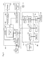
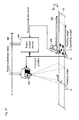
- Fig. 2 is a schematic diagram illustrating a hardware configuration of the conveyer tracking system in which the visual sensor according to the first embodiment of the present invention is used.
- the visual sensor 100 includes the imaging unit 110 and the captured image processing unit 120.
- the captured image processing unit 120 conducts communication with the operation display device 500.
- the robot control device 200 and the support device 600 are not illustrated in Fig. 2 .
- the image processing device that receives and processes the captured image obtained by the imaging of the imaging unit 110 includes the captured image processing unit 120 and the operation display device 500.
- the support device 600 may include the function of the operation display device 500.
- the image processing device is configured while including the functions of the captured image processing unit 120 and the support device 600.
- the imaging unit 110 is a device that captures the image of the subject existing in the imaging visual field.
- the imaging unit 110 includes an optical system such as a lens and a diaphragm and light receiving element such as a CCD (Charge Coupled Device) image sensor and a CMOS (Complementary Metal Oxide Semiconductor) image sensor as a main structural element.
- the imaging unit 110 performs the imaging in response to the instruction from the captured image processing unit 120, and outputs the image data obtained by the imaging to the captured image processing unit 120.
- the captured image processing unit 120 includes a CPU (Central Processing Unit) 122, a memory 124, an image control unit 126, a communication interface (interface) 128, an input and output interface (interface) 130, an encoder counter 132, and a memory interface (interface) 135 in which a CD-ROM (Compact Disk-Read Only Memory) 136 that is of an example of a detachable recording medium is loaded.
- CPU Central Processing Unit
- memory 124 volatile and non-volatile memory
- an image control unit 126 includes a communication interface (interface) 128, an input and output interface (interface) 130, an encoder counter 132, and a memory interface (interface) 135 in which a CD-ROM (Compact Disk-Read Only Memory) 136 that is of an example of a detachable recording medium is loaded.
- a bus 134 so as to be able to conduct data communication with one another.
- the CPU 122 is a processor that performs a main calculation in the captured image processing unit 120.
- Various programs executed by the CPU 122, the image data captured by the imaging unit 110, and various parameters are stored in the memory 124.
- the memory 124 includes a volatile storage device such as a DRAM (Dynamic Random Access Memory) and a nonvolatile storage device such as a FLASH memory.
- the image control unit 126 performs the imaging action in the connected imaging unit 110 in response to an internal command from the CPU 122 or the like.
- the image control unit 126 includes an interface that transmits various commands to the imaging unit 110 and an interface that receives the image data from the imaging unit 110.
- the communication interface 128 exchanges various pieces of data with operation display device 500.
- the visual sensor 100 and the operation display device 500 are connected to each other through Ethernet (registered trademark), and the communication interface 128 is hardware compliant with Ethernet (registered trademark).
- the input and output interface 130 outputs various signals to the outside from the captured image processing unit 120, and inputs various signals from the outside. Particularly, the input and output interface 130 receives the pulse signal generated by the encoder 14, converts the pulse signal into a digital signal, and outputs the digital signal to the encoder counter 132.
- the encoder counter 132 counts the number of pulses included in the pulse signal from the encoder 14, and outputs a count value. Because basically the encoder counter 132 performs the action independently of a calculation cycle of the CPU 122, the encoder counter 132 certainly catches the number of pulses included in the pulse signal from the encoder 14.
- the operation display device 500 includes a computation processing unit 510 including a memory 520, a communication interface (interface) 528, an input and output interface (interface) 550, a display controller 540 that controls display action of an external display 502 such as a liquid crystal display, an input interface (interface) 550 that receives an operation from an operation unit 503 constructed by a button and a switch, which are operated by the operator, and a memory interface (interface) 529 in which a memory card 531 that is of an example of the detachable recording medium is mounted.
- These components are constructed by various processors such as a display DSP (Digital Signal Processor).
- the display 502 and the operation unit 503 are separately provided.
- what is called a touch panel in which the display 502 and the operation unit 503 are integrally constructed may be provided.
- the computation processing unit 510 receives the image data from the visual sensor 100 and controls the display controller 540 using the received image data, thereby causing the display 502 to display the image or inputting the instruction provided by the operator's operation of the operation unit 503 through the input interface 550.
- the image data received from the visual sensor 100 is stored in the memory 220.
- Information on the measurement result of the workpiece W detected by the measurement processing of the visual sensor 100 is also stored in the memory 220.
- the communication interface (interface) 528 exchanges various pieces of data with the captured image processing unit 120 of the visual sensor 100.
- the visual sensor 100 and the operation display device 500 are connected to each other through Ethernet (registered trademark), and the communication interface 528 is hardware compliant with Ethernet (registered trademark).
- Fig. 3 is a schematic diagram illustrating a functional configuration of captured image processing according to the first embodiment of the present invention.
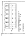
- Fig. 4 is a schematic diagram illustrating a data storage content of the captured image processing according to the first embodiment of the present invention.
- each function in Fig. 3 is implemented such that the CPU 122 of the captured image processing unit 120 executes the program previously stored in the memory 124.
- each function may be implemented by not only the program but also a combination of the program and a circuit.
- Various programs executed by the captured image processing unit 120 are distributed while stored in the CD-ROM 136.
- the programs stored in the CD-ROM 136 are read by the memory interface 135 having a CD-ROM (Compact Disk-Read Only Memory) drive function, and stored in the memory 124 and the like.
- the program may be downloaded from an upper-level host computer through the network NW.
- the imaging unit 110 connects the pieces of image data acquired by continuously capturing the imaging range, thereby generating the image corresponding to a full view from upstream to downstream on the line 1.
- the image corresponding to the full view is called a panoramic image.
- the CPU 122 has a function to process the panoramic image.
- the CPU 122 includes a measurement processing unit 221 that performs the workpiece measurement processing to the captured image, an overlapping acquisition unit 222 that acquires an overlapping range between the images of the panoramic image, an image generation unit 223 that generates the panoramic image in which the images overlap with each other in the overlapping range, a ratio acquisition unit 225 that acquires a ratio of a time necessary for the measurement processing to an imaging interval, a parameter update unit 226 that updates various parameters (types and/or values of parameters), and an image division unit 229 that divides the panoramic image into the captured images.
- the parameter update unit 226 includes a measurement parameter update unit 227 that updates the parameter related to the measurement processing and an imaging parameter update unit 228 that updates the parameter related to the imaging interval.
- Search processing in which pattern matching is used based on a model image of the previously-registered workpiece W can be cited as a typical example of the measurement processing.
- a feature portion of the workpiece W is previously registered as an image pattern (model) and a portion most similar to the previously-registered model is searched from the input image.
- a position, an inclination, and a rotation angle of the portion most similar to the model and a correlation value indicating how much similar to the model are calculated.
- labeling processing is applied, a portion matched with the previously-registered model or display attribute (such as a color) is searched from the input image, and a label (a number) is added to the searched portion.
- an area or a gravity center of the designated portion is calculated using the number.
- the measurement processing unit 221 outputs the position and the correlation value of the workpiece W calculated by the pattern matching as the measurement result, and that the parameter (the type and the value) of the measurement processing indicates the type and the value of a correlation coefficient used to calculate the correlation value.
- image data 333 of the captured image output from the imaging unit 110 a table 331 in which data related to each piece of image data 333 is stored, panoramic image data 332, and data including imaging parameter 350 are stored in the memory 124.
- the data related to the image data 333 of the captured image acquired every time of the imaging includes a measurement result 334 of the measurement processing performed to the image data 333, a deviation amount 335, a counter value 336 input from the encoder counter in capturing the image data 333, a parameter (the type and the value) 337 of the measurement processing performed to the image data 333, and an imaging interval 339.
- the measurement result 334 includes the correlation value and an image coordinate position, which are acquired when the measurement processing unit 221 performs the measurement processing to the corresponding image data 333.
- the parameter 337 indicates the type or the value of the correlation coefficient used to calculate the correlation value.
- Fig. 5 is a view illustrating a procedure to generate the panoramic image according to the first embodiment of the present invention.
- the panoramic image generation processing performed by the image generation unit 223 will be described with reference to Fig. 5 .
- the panoramic image may be generated by a well-known panoramic synthesizing technology. However, at this point, the panoramic image generation processing in which the counter value 336 of the encoder counter is used will be described below.
- the overlapping acquisition unit 222 acquires the deviation amount 335 of each piece of image data 333, and the deviation amount 335 is stored in the table 331. Specifically, the overlapping acquisition unit 222 acquires the counter value 336 from the encoder counter 132 during the imaging, and stores the counter value 336 in the table 331 while correlating the counter value 336 with the image data 333 of the captured image. Thus, every time the captured image is acquired, the image data 333 and the counter value 336 are acquired and stored in the table 331.
- the overlapping acquisition unit 222 can calculate the deviation amount M between the Nth and (N+1)-th pieces of image data 333 using the counter value 336 read from the table 331.
- the calculated deviation amount M is stored as the deviation amount 335 in the table 331.
- the deviation amount 335 corresponding to image data D(i) corresponds to the deviation amount M between image data D(i) and image data D(i+1).
- the panoramic image generation performed by the image generation unit 223 will be described below.
- the image generation unit 223 generates the panoramic image every time the CPU 122 receives a monitor instruction from the operation display device 500.
- the image data 333 captured and acquired by the imaging unit 110 is stored in the table 331 in the imaging order. In generating the panoramic image, it is assumed that the number of pieces of image data 333 necessary to generate the panoramic image is stored in the table 331.
- the image generation unit 223 When receiving the monitor instruction, the image generation unit 223 sequentially reads the Nth and (N+1)-th pieces of image data 333 from the table 331, namely, reads the pieces of image data 333 in the imaging order, and arrays the pieces of image data 333 in a predetermined area of the memory 124 in the order in which the pieces of image data 333 are read from the table 331.
- the panoramic image data 332 includes the plural pieces of image data 333 used to generate the panoramic image, the measurement result 334 related to each piece of image data 333 read from the table 331, the deviation amount 335, a position 338 of the image in the panoramic image, and a ratio 340.
- the ratio 340 is described in detail later.
- the image generation unit 223 determines the position 338 in the following manner. At this point, a size of the panoramic image is previously determined according to a size of the display 502, and a size of the image data 333 is previously determined. Accordingly, when the number of pieces of image data 333 constituting the panoramic image is determined, the position of each piece of image data 333 in the panoramic image is uniquely determined by the deviation amount 335.
- the image generation unit 223 Every time the image generation unit 223 generates the panoramic image data 332, the image generation unit 223 sets a pointer 360 to the table 331.
- the pointer 360 indicates the finally-read image data 333, namely, the latest image data 333 in the plural pieces of image data 333 used to generate the panoramic image data 332.
- the image generation unit 223 When the monitor instruction is input next, the image generation unit 223 generates the data of the new panoramic image using the image data 333 that is stored subsequent to the image data 333 indicated by the pointer 360.
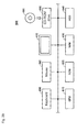
- Fig. 6 is a main flowchart of processing according to the first embodiment of the present invention.
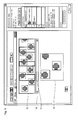
- Fig. 7 is a schematic diagram illustrating the panoramic image of the first embodiment of the present invention.
- the lower-stage panoramic image is generated by overlapping the pieces of image data 333 of the upper-stage captured images according to the corresponding deviation amount 335 in the imaging order.
- Each piece of image data 333 includes an image 60 of the workpiece conveyed on the line 1.
- An image 61 of the measurement processing result for each piece of image data and an image 62 of the overlapping region are simultaneously displayed together with each piece of image data while overlaid (superimposed) on the panoramic image.
- the measurement processing result is displayed by the image 61.
- the measurement processing result is not limited to the superimposed image, but the measurement processing result may be displayed by an individual graph or numerical value.
- the overlapping region is superimposed and displayed by the image 62. However, the overlapping region is not limited to the superposition mode. The overlapping region may be displayed in any way as long as the overlapping region is correlated with the panoramic image.
- the panoramic image generation and display procedure in Fig. 7 will be described with reference to the flowchart in Fig. 6 .
- the CPU 122 reads the panoramic image data 332 generated by the image generation unit 223 from the table 331, and transmits the panoramic image data 332 to the operation display device 500. Therefore, the computation processing unit 510 of the operation display device 500 receives the panoramic image data 332 through the communication interface 528 (Step S1). The received panoramic image data 332 is stored in the memory 520.
- the computation processing unit 510 displays each piece of image data 333 of the panoramic image data 332 from the memory 520 on the display 502 while overlapping the image data 333 according to the deviation amount 335 and the position 338, which are correlated with each other (Step S2). Therefore, the panoramic image is displayed on the display 502.
- the computation processing unit 510 reads the measurement result 334 correlated with each piece of image data 333 from the memory 520, and displays the image 61 on the panoramic image of the display 502 based on the measurement result 334 (Step S3).
- the display position of the image 61 can be determined by the image coordinate position included in the measurement result 334.
- the image 62 expressing the overlapping region between the pieces of image data 333 is simultaneously displayed on the panoramic image (Step S3).
- the operator performs the operation to continue or interrupt the monitor using the operation unit 503.
- the input interface 550 receives and outputs the instruction to continue or interrupt the monitor in response to the operation.
- the computation processing unit 510 determines the continuation or the interruption of the monitor based on the input instruction (Step S4).
- the sequence of pieces of processing is ended when the computation processing unit 510 determines the interruption of the monitor (YES in Step S4).
- the processing returns to Step S1 when the computation processing unit 510 determines the continuation of the monitor (NO in Step S4). Therefore, the computation processing unit 510 transmits the monitor instruction to the captured image processing unit 120 through the communication interface 528.
- the image generation unit 223 of the captured image processing unit 120 generates the next panoramic image data 332 in response to the received monitor instruction. Then, because the pieces of processing from Step S1 are performed to the newly-generated panoramic image data 332, the operator can monitor the line 1 using the new panoramic image displayed on the display 502.
- the panoramic image at the lower stage in Fig. 7 is displayed on the display 502, so that the operator can simultaneously check the image 61 of the measurement processing result and the image 62 of the overlapping region. Whether the visual sensor 100 detects the workpiece is determined by checking the images 60 and 61.
- the operator can check the imaging interval by checking the image 62 of the overlapping region, it can be determined that which one of the measurement processing and the imaging interval causes the workpiece to be not able to be detected.
- the panoramic image of the first embodiment is not limited to the display mode in Fig. 7 , but the following display modes may be used.
- Fig. 8 is a view illustrating other examples of a panoramic image display mode according to the first embodiment of the present invention.
- the image 61 may be displayed while correlated wit the image 60 of the workpiece based on the measurement processing result, and the image 62 of the overlapping region may be surrounded by a thick-line frame.
- the image 61 may be displayed while color-coded according to the value (the correlation value) of the measurement processing result.
- the image 62 of the overlapping region may be displayed by a predetermined color 63.
- the Nth image and the (N+1)-th image namely, the odd-numbered image and the even-numbered image may differ from each other in the display mode.
- the odd-numbered image and the even-numbered image may be displayed while background colors 64 vary.
- Fig. 9 is a view illustrating scroll of the panoramic image according to the first embodiment of the present invention.
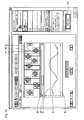
- the display region of the display 502 includes a display region 72 for the panoramic image, a display region for a slide bar 70, and a display region for a selected image 73.
- the panoramic image in which the plural images are horizontally arrayed in line is displayed in the region 72, and an extending direction of the slide bar 70 is identical to the direction in which the image array extends.
- the operator operates the slider 71 on the slide bar 70.
- the computation processing unit 510 detects the travel distance (a moving direction and a moving distance) of the slider 71 through the input interface 550, and outputs a scroll instruction related to the detected travel distance to the display controller 540.
- the display controller 540 moves the image (the panoramic image) of the region 72, namely, displays the image of the region 72 while scrolling the image.
- the panoramic image data 332 including the sufficient number of pieces of image data 333 is stored in the memory 529 such that the scroll can be performed.
- the operator can select the desired image from the plural images in the panoramic image displayed on the region 72.
- the computation processing unit 510 detects a click position of a click operation through the input interface 550.
- the image data 333 corresponding to the selected image is enlarged and displayed as the selected image 73 based on the detected click position and the position 338 of the panoramic image data 332.
- Fig. 10 is a main flowchart of processing according to the second embodiment of the present invention.
- the parameter related to the measurement processing is changed in the processing in Fig. 10 .
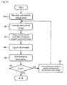
- the CPU 122 reads the panoramic image data 332 generated by the image generation unit 223 from the table 331, and transmits the panoramic image data 332 to the operation display device 500. Therefore, the computation processing unit 510 of the operation display device 500 receives the panoramic image data 332 through the communication interface 528 (Step S1a). The received panoramic image data 332 is stored in the memory 520.
- Steps S2 and S3 similarly to the first embodiment, the panoramic image is displayed on the display 502, and the image 61 of the measurement processing result and the image 62 of the overlapping region are simultaneously displayed while overlaid on the panoramic image.
- the operator operates the operation unit 503 to input the information for changing the parameter (Step S4a). Specifically, the operator inputs the information on the type of the parameter and the information indicating the post-change value.
- the computation processing unit 510 transmits the information for changing the parameter to the captured image processing unit 120 through the communication interface 528.
- the captured image processing unit 120 receives the information for changing the parameter. Using the received information, the measurement parameter update unit 227 updates the parameter (such as the type and the value) for the measurement processing, and outputs the post-update parameter to the measurement processing unit 221.
- the measurement parameter update unit 227 updates the parameter (such as the type and the value) for the measurement processing, and outputs the post-update parameter to the measurement processing unit 221.
- the measurement processing unit 221 uses the post-change parameter to perform the measurement processing to each piece of image data 333 in the currently-displayed panoramic image.
- the measurement result 334 related to the each piece of image data 333 in each piece of panoramic image data 332 of the memory 124 is updated using the measurement result (Step S5). Therefore, the panoramic image data 332 of the memory 124 is edited (updated) into data having the measurement result 334, which is obtained by the measurement processing using the post-update parameter.
- the operator makes a request for an operation to check an edit result through the operation unit 503.
- the computation processing unit 510 inputs a checking instruction in response to the operation.
- the computation processing unit 510 ends the sequence of pieces of processing. On the other hand, when it is determined that the checking instruction is input (NO in Step S6), the computation processing unit 510 transmits the checking instruction to the captured image processing unit 120.
- the CPU 122 when receiving the checking instruction, the CPU 122 reads the post-edit panoramic image data 332 from the memory 124 and transmits the post-edit panoramic image data 332 to the operation display device 500. Therefore, the pieces of processing from Step S1 are performed using the post-edit panoramic image data 332. Accordingly, using the panoramic image, the operator can check the measurement processing result, which is obtained by using the post-update parameter.
- the panoramic image in which the parameter is already updated is acquired by editing the panoramic image data 332 that is already generated and stored in the memory 124.
- the panoramic image acquiring method is not limited to the method of the second embodiment.
- the newly-captured and -acquired image data 333 may be used.
- the new panoramic image data 332 may be generated by performing the measurement processing using the post-update parameters for the pieces of image data 333 from the image data 333 indicated by the pointer 360.
- the parameter 337 of the table 331 may be updated using the post-update parameter. Particularly, as needed basis, the parameter 337 of the table 331 may be updated when the operator inputs the update instruction through the operation unit 503.
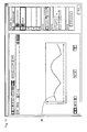
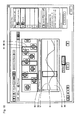
- Figs. 11 to 13 are views illustrating the panoramic image display mode according to the second embodiment of the present invention.
- the value of the measurement result 334 is extracted and displayed such that the operator easily understands an indication of the post-update value.
- a vertical axis indicating the value of the measurement result 334 and a horizontal axis orthogonal to the vertical axis are displayed on the display 502.
- the horizontal axis indicates the value expressing the position of each piece of image data 333 in the panoramic image.
- the position is acquired based on the position 338.
- the value indicated by the vertical axis expresses the correlation value.
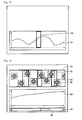
- a graph 91 is generated by connecting the correlation values corresponding to the pieces of image data 333 using line divisions. The operator can quickly understand whether the image data 333 in which the value of the measurement result 334 is high or low exists from the graph 91.
- Fig. 12 illustrates a state in which a portion 92 of the graph 91 is selectively designated in response to the operator's operation.
- the portion 92 is displayed in the mode in which the portion 92 can be distinguished from the graph 91.
- the frame of the portion 92 is displayed in red.
- the computation processing unit 510 extracts the horizontal-axis value corresponding to the portion 92 through the input interface 550.
- the image data 333, the data of the measurement result 334, and the data of the deviation amount 335, which are correlated with the position 338 corresponding to the extracted value, are read from the memory 520, and the image is displayed on the display 502 based on the read pieces of data (see Fig. 13 ).
- Fig. 13 illustrates the state in which the image corresponding to the portion 92 is enlarged and displayed.
- a panoramic image 93 is displayed on the upper stage, and a graph 911 is displayed on the lower stage in relation to the panoramic image 93.
- the upper-stage panoramic image 93 includes the image data 333 corresponding to the portion 92 of the selected measurement result and the pieces of image data 333 that are acquired before and after the image data 333 concerned.
- a slide bar 94 is displayed in the direction identical to the direction in which the horizontal axis of the graph 911 extends. The operator can operate a slider 95 on a slide bar 94.
- the computation processing unit 510 moves and displays the portion 92 based on the travel distance (the moving direction and the moving distance) of the slider 95 by the slide operation.
- the image data 333, the data of the measurement result 334, and the data of the deviation amount 335, which are correlated with the post-movement position 338 of the portion 92, are read from the panoramic image data 332 of the memory 520, and the image is enlarged and displayed on the display 502 based on the read pieces of data. Therefore, the panoramic image and the graph 911 in Fig. 13 can be scroll-displayed in conjunction with the slide operation.
- the horizontal axis of the graph 91 indicates the value of the position 338
- the horizontal axis may indicate the counter value 336 instead of the position 338.
- the graph 911 and the panoramic image 93 may have display modes in Figs. 14 to 17 .
- Fig. 14 the display of the image 61 of the measurement result is not given in the panoramic image 93 of Fig. 13 .
- Fig. 15 only the panoramic image 93 is displayed.
- Fig. 16 instead of the graph 911 in Fig. 11 , only the correlation value of the measurement result of each workpiece W is displayed by a point 912 plotted in relation to the image 60 of the upper-stage workpiece W.
- Fig. 17 only the image 60 of the workpiece is displayed while the image 62 is eliminated from the panoramic image 93 in Fig. 16 .
- the plotted points 912 may be connected to each other in Fig. 16 or 17 .
- the operator can switch the image displayed on the display 502 to one of the image in Fig. 13 and the images in Figs. 14 to 17 by operating the operation unit 503.
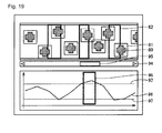
- Figs. 18 and 19 illustrate screens on which the measurement result is displayed using the threshold.
- the computation processing unit 510 compares the value (specifically, the correlation value) of each measurement result 334 of the graph 91 to a threshold 97. Based on a comparison result, in the graph 91, the computation processing unit 510 displays an image 96 expressing a portion in the range of the threshold 97 while superimposing the image 96 on the graph 91 (see Fig. 18 ). For example, the image 96 is displayed by the frame, and the frame is displayed in the mode different from that of the graph 91. For example, the frame differs from the graph 91 in color.
- the computation processing unit 510 displays the image 96 while sequentially moving the image 96 to another portion (in the graph 91, the portion in the range of the threshold 97) of the graph 91.
- the image 96 in Fig. 18 indicates the portion in the range of the threshold 97.
- the image 96 may indicate a portion out of the range of the threshold 97.
- overlapping measurement In order that the robot 300 accurately holds the workpiece W, it is necessary to eliminate a situation (hereinafter referred to as overlapping measurement) in which the measurement processing is performed at least twice to the identical workpiece W on the line 1.
- the information assisting the overlapping measurement is displayed in the second embodiment.
- Fig. 20 is a view illustrating an example of the panoramic image for removing the overlapping measurement according to the second embodiment of the present invention.
- the computation processing unit 510 displays the image 61 based on the measurement result 334 while the even-numbered image and the odd-numbered image in the panoramic image differ from each other in the display mode. For example, in Fig. 20 , an image 61A based on the measurement result in the even-numbered image and an image 61 B based on the measurement result in the odd-numbered image are displayed in different colors.
- Fig. 21 is a view illustrating a screen example on which a ratio of a measurement processing time to the imaging interval according to the second embodiment of the present invention.
- a degree of margin of the measurement processing time is indicated by the ratio of the measurement processing time to the imaging interval.
- the imaging interval and the measurement processing time are acquired as follows.
- the CPU 122 calculates the imaging interval from ((It x a)/v).
- It [pulse] is an interval at which the imaging instruction is input
- a [mm/pulse] is the conveyer travel distance per pulse
- v [mm/sec] is a conveyer speed. It is assumed that these values are previously stored as the imaging parameter 350 in the memory 124.
- the calculated imaging interval is stored as the data of the imaging interval 339 in the table 331 while correlated with the image data 333 acquired by the imaging action.
- the measurement processing time means a time from when the measurement processing unit 221 starts the measurement processing to the image data 333 acquired by the one-time imaging action to when the measurement processing unit 221 ends the measurement processing.
- the time between the beginning and end of the measurement processing means the time from when the measurement processing unit 221 inputs the image data from the imaging unit 110 to when the measurement processing unit 221 outputs the measurement processing result.
- the time can be acquired such that the CPU 122 performs measurement with a timer (not illustrated). At this point, a measurement processing time T [sec] is used for the sake of convenience.
- the ratio acquisition unit 225 acquires the data of the ratio 340. That is, using the imaging interval 339 correlated with the image data 333 and the measurement processing time T, the ratio of the measurement processing time to the imaging interval is calculated from (measurement processing time (T) / imaging interval) with respect to each piece of image data 333 of the panoramic image data 332 of the memory 520. The ratio calculated with respect to each piece of image data 333 is registered as the ratio 340 while correlated with each piece of image data 333 of the panoramic image data 332.
- the computation processing unit 510 displays the information based on the ratio 340. Specifically, the image of a graph 133 (see Fig. 21 ) is generated using the data of the ratio 340, which is received from the captured image processing unit 120 and correlated with each piece of image data 333 of the panoramic image data 332 stored in the memory 520, and the generated graph 133 is displayed on the display 502 through the display controller 540.
- the vertical axis indicates the value of the ratio 340
- the horizontal axis orthogonal to the vertical axis indicates the value of the position 338 of each piece of image data 333 of the panoramic image.
- the value of the ratio 340 correlated with each piece of image data 333 is displayed by the bar graph.
- the display mode of the value of the ratio is not limited to the bar graph.
- the measurement processing of the corresponding image data 333 is not ended within the imaging interval when the value of the ratio 340 is greater than "1", and the measurement processing time has the margin when the value of the ratio 340 is less than "1". Accordingly, from the graph 133, the operator can quickly understand whether the image data 333 in which the measurement processing is not ended within the imaging interval exists in the panoramic image.
- the operator can obtain assist information determining whether the value of the variable It [pulse] or the conveyer speed is proper from the graph 133. Specifically, the operator can obtain the information assisting the determination whether the setting is changed such that the value of the variable It [pulse] is decreased or such that the conveyer speed is enhanced.
- the display mode is changed with respect to the portion in which the value of the ratio 340 is greater than "1".
- the portion is highlighted by surrounding the portion using the frame 131.
- the color of the bar graph corresponding to each piece of image data 333 may be changed according to the degree of margin of the measurement processing time.
- the computation processing unit 510 controls the display controller 540 such that the travel distance (the moving direction and the moving distance) of the slider 95 is input, such that the panoramic image is scrolled in conjunction with the input travel distance, and such that the graph 133 is scrolled at the same time.
- the degree of margin of the measurement processing time can be presented. Accordingly, in the case that the operator determines whether the measurement processing time in which the post-change parameter is used has the margin after measurement processing parameter is changed in Step S5 of Fig. 10 , the information assisting the determination can be presented. Not only the ratio of the measurement processing time to the imaging interval but also the measurement processing time of itself may be displayed in order to present the degree of margin of the measurement processing time.
- Fig. 22 illustrates a screen example in which the parameter is changed in Step S5.
- the operator can input an instruction to change the measurement processing parameter by operating a button 171 on the screen.
- the computation processing unit 510 switches the screen of the display 502 to another screen (not illustrated) used to adjust the parameter. For example, the type of the parameter and the range of the value are displayed on the screen used to adjust the parameter.
- Fig. 23 is a flowchart of processing of changing the imaging parameter according to the second embodiment of the present invention.
- the measurement processing parameter is changed in Fig. 10 , and similarly the parameter related to the imaging action can be changed.
- Steps S1 a to S3 are performed similarly to Fig. 10 . Therefore, the panoramic image or the graph of the measurement result is displayed on the display 502.
- Step S4b the operator can input the information for changing the parameter related to the imaging action by operating the operation unit 503 (Step S4b). Specifically, the type of the parameter and the post-change value are input.
- the computation processing unit 510 transmits the information for changing the parameter to the captured image processing unit 120 through the communication interface 528.
- the imaging parameter update unit 228 updates the imaging parameter 350 of the memory 124 using the received information. For example, the parameter determining the deviation amount M in Fig. 5 can be updated.
- the processing is ended when the instruction to check the measurement result using the post-change parameter is not input through the operation unit 503 (YES in Step S6).
- the processing is performed using the post-change parameter (Step S7).
- Step S7 the measurement processing is performed using the post-change parameter.
- the data of the panoramic image is acquired by simulating the imaging action of the imaging unit 110 at the times of T(n) and T(n+1) after the parameter is updated.
- the image division unit 229 inputs the post-change counter values T(n) and T(n+1) from the imaging parameter update unit 228, and calculates the deviation amount M according the procedure in Fig. 5 using the values T(n) and T(n+1).
- the calculated deviation amount is referred to as a post-change deviation amount MM.
- the image division unit 229 sequentially extracts the panoramic image of the panoramic image data 332 of the memory 124 from the head image data 333 to the final image data 333. Therefore, the panoramic image data 332 can be divided into the plural pieces of image data 333 constituting the panoramic image.
- Each piece of image data 333 acquired by the division indicates the image data that is acquired when the imaging unit 110 is considered to perform the imaging action at the times of the post-change values T(n) and T(n+1).
- the acquisition of the image data 333 corresponds to the simulation of the imaging action of the imaging unit 110 at the times of the post-change values T(n) and T(n+1).
- the measurement processing unit 221 performs the measurement processing to each piece of image data 333 acquired by the image division unit 229 , and outputs the measurement result 334.
- the panoramic image data 332 is generated using the output measurement result 334 and the post-change deviation amount MM. Therefore, the post-update panoramic image data is acquired to end the processing in Step S7.
- Step S2 the post-update panoramic image data is transmitted to the operation display device 500 from the captured image processing unit 120.
- the computation processing unit 510 of the operation display device 500 displays the post-update panoramic image on the display 502 using the received post-update panoramic image data, and simultaneously displays the image of the overlapping region and the image of the measurement result (Step S3).
- the operator can check the measurement result while correlating the measurement result with the post-update panoramic image displayed on the display 502. Therefore, the assist information determining whether the value of the post-update imaging parameter is proper can be obtained.
- the calibration that converts an image coordinate system of the visual sensor 100 into the robot coordinate system of the robot 300 will be described below.
- Fig. 24 is a view illustrating the calibration according to the third embodiment of the present invention.
- Fig. 25 is a view illustrating an example of a parameter set acquired by the calibration shown in Fig. 24 .
- Figs. 26 to 28 are views illustrating the procedure of the calibration according to the third embodiment of the present invention.
- the calibration is mainly performed from the following two viewpoints.
- the positional information (a robot coordinate value) on the robot 300 is necessary to perform the calibration, the positional information is transferred to the visual sensor 100 from the robot control device 200 through the network NW.
- the calibration procedure will be described in detail below.
- the calibration of the third embodiment is performed by a three-stage procedure in Figs. 26 to 28 .
- a calibration sheet S in which a target pattern illustrated at the uppermost stage in Fig. 25 is drawn is used in the calibration of the third embodiment.
- the target pattern illustrated in the calibration sheet S includes five circles (marks) in each of which an inside is two-toned by about 90°.
- the calibration is basically performed using the four marks as described later.
- the additionally-disposed mark is used to align the calibration sheet S with a predetermined direction.
- the user disposes the calibration sheet S in which the target pattern is drawn in the visual field of the visual sensor 100 (the imaging unit 110).
- the user provides the imaging instruction to the visual sensor 100.
- the visual sensor 100 performs the measurement processing to the image (the image including the target pattern as the subject) obtained by the imaging, and determines a coordinate value of a center point of each of the four marks disposed at four corners included in the target pattern. Therefore, the coordinate value [pixel] of the image coordinate system is acquired for each of the four marks included in the target pattern.
- the four acquired coordinate values correspond to (xi1, yi1), (xi2, yi2), (xi3, yi3), and (xi4, yi4) indicated at the uppermost stage in Fig. 25 .
- the user moves the conveyer 10 to dispose the calibration sheet S in which the target pattern is drawn within the tracking range (the operating range) of the robot 300, and operates the robot 300 to obtain the positional relationship between the four marks included in the target pattern and the robot 300.
- the user moves the conveyer 10 to dispose the calibration sheet S within the tracking range (the operating range) of the robot 300. It is assumed that the count value before the movement of the conveyer 10 (at the beginning of the calibration) is previously acquired. The count value corresponds to an encoder count value E1 (at the beginning of the calibration) indicated in the second top of Fig. 25 .
- the user positions a front end of a hand of the robot 300 such that the front end of the hand of the robot 300 is opposed to one of the marks on the calibration sheet S.
- the user provides the instruction in the positioned state to transmit the positional information (the coordinate value of the robot coordinate system indicating the position of the front end of the hand of the robot 300) on the robot 300, which is possessed by the robot control device 200, to the visual sensor 100.
- the processing of positioning the front end of the hand of the robot 300 to transmit the positional information on the robot 300 to the visual sensor 100 is repeatedly performed to all the four marks included in the target pattern.
- the positional information on the robot 300 corresponding to each of the four marks included in the target pattern is acquired by the above procedure.
- the pieces of positional information on the robot 300 corresponding to the acquired four marks correspond to (X1, Y1), (X2, Y2), (X3, Y3), and (X4, Y4) indicated in the third top of Fig. 25 .
- the state in which the calibration sheet S is disposed within the tracking range (the operating range) of the robot 300 is maintained until the pieces of positional information on the robot 300 corresponding to the four marks are transmitted to the visual sensor 100.
- the count value in the state of Fig. 27 is also stored in the visual sensor 100.
- the count value corresponds to an encoder count value E2 (when the conveyer is moved to the robot operating range (the upstream side)) indicated in the second top of Fig. 25 .
- the user further moves the conveyer 10 to dispose the calibration sheet S to the most downstream position in the tracking range (the operating range) of the robot 300, and operates the robot 300 to obtain the positional relationship between the one mark included in the target pattern and the robot 300.
- the user moves the conveyer 10 to dispose the calibration sheet S in the position of the end portion on the downstream side in the tracking range (the operating range) of the robot 300.
- the user positions the front end of the hand of the robot 300 such that the front end of the hand of the robot 300 is opposed to the first mark (the mark in which the coordinate value (X1, Y1) is acquired at the second stage) on the calibration sheet S.
- the user provides the instruction in the positioned state to transmit the positional information (the coordinate value of the robot coordinate system indicating the position of the front end of the hand of the robot 300) on the robot 300, which is possessed by the robot control device 200, to the visual sensor 100.
- the positional information on the robot 300 corresponding to the first mark included in the target pattern is acquired by the above procedure.
- the positional information on the robot 300 corresponding to the acquired first mark correspond to (X5, Y5) indicated in the fourth top of Fig. 25 .
- the count value in the state of Fig. 28 is also stored in the visual sensor 100.
- the count value corresponds to an encoder count value E3 (when the conveyer is moved to the robot operating range (the downstream side)) indicated in the second top of Fig. 25 .
- Workpiece travel distances dX and dY per count from the encoder 14 are calculated using the parameters acquired by the pieces of processing at the first to third stages. More specifically, the workpiece travel distances dX and dY are calculated according to the following equations.
- dX X ⁇ 5 - X ⁇ 1 / E ⁇ 3 - E ⁇ 2
- dY Y ⁇ 5 - Y ⁇ 1 / E ⁇ 3 - E ⁇ 2
- the six parameters A to F of the conversion formulas related to the conversion of the coordinate system are determined based on a correspondence relationship between the coordinate values (xi1, yi1), (xi2, yi2), (xi3, yi3), and (xi4, yi4) of the camera coordinate system acquired in Fig. 26 and the coordinate values (X1, Y1), (X2, Y2), (X3, Y3), and (X4, Y4) of the robot coordinate system acquired in Fig. 27 . That is, the parameters A to F satisfying the following equations (or in which an error is minimized) are determined using a well-known technique.
- the CPU 122 may convert the panoramic image of the camera coordinate system into the coordinate value of the robot coordinate system using the parameters A to F. Therefore, the disposition of the workpiece W on the conveyance path can be presented to the operator at the time when the robot 300 holds the workpiece W.
- each workpiece position (coordinate value) indicated by the measurement result 334 of the panoramic image data 332 is converted into the coordinate value of the robot coordinate system using the parameters A to F, and the image 60 of each workpiece is displayed in the panoramic image according to the post-conversion coordinate value. Therefore, the disposition of the workpiece W on the conveyance path can be presented at the time when the robot 300 holds the workpiece W.
- the support device 600 that is connected to the visual sensor 100 and the robot control device 200 through the network NW will be described below.
- Fig. 29 is a schematic diagram illustrating a hardware configuration of a support device 600 according to a fourth embodiment of the present invention.
- the support device 600 is constructed by a general-purpose computer.
- the support device 600 is constructed by a notebook personal computer having excellent portability from the viewpoint of maintenance.
- the support device 600 includes a CPU 610 that executes various programs including the OS (Operating System), a ROM (Read Only Memory) 620 in which the BIOS and various pieces of data are stored, a memory RAM 630 that provides a working area in which the data necessary for the CPU 61 to execute the program is stored, and a hard disk drive (HDD) 640 in which the program and the like executed by the CPU 61 are stored in a nonvolatile manner.
- OS Operating System
- ROM Read Only Memory
- memory RAM 630 that provides a working area in which the data necessary for the CPU 61 to execute the program is stored
- HDD hard disk drive
- the support device 600 also includes a keyboard 650 and a mouse 660, which receive the operation from the user, and a monitor 670 that presents the information to the user.
- various programs executed by the support device 600 is distributed while stored in a CD-ROM 690.
- the program stored in the CD-ROM 690 is read by a CD-ROM (Compact Disk-Read Only Memory) drive 68, and stored in the hard disk drive (HDD) 640.
- the program may be downloaded from the upper-level host computer through the network.
- the support device 600 is constructed by the general-purpose computer, the detailed description is not repeated.
- the support device 600 can conduct data communication with both the visual sensor 100 and the robot control device 200, the support device 600 can collect various pieces of data.
- the support device 600 may have the function related to the panoramic image display of the operation display device 500.
- the table 331 in which the measurement result of each piece of image data 333 is stored can be used in order to analyze the action of the robot 300. That is, the robot action is recorded in the robot 300 while correlated with the counter value, which allows the robot action to be correlated with the measurement result 334 of the image corresponding to the robot action. Therefore, for example, in the case that the robot 300 fails in the holding action, the image of the workpiece that is of the holding target and the measurement result 334 can be reproduced on the support device 600 or the operation display device 500 in order to the pursue a cause of the failure. Therefore, the cause of the failure can easily be analyzed, or the information assisting the analysis can be presented.
Landscapes
- Engineering & Computer Science (AREA)
- Physics & Mathematics (AREA)
- General Physics & Mathematics (AREA)
- Theoretical Computer Science (AREA)
- Computer Vision & Pattern Recognition (AREA)
- Multimedia (AREA)
- Signal Processing (AREA)
- Image Processing (AREA)
- Length Measuring Devices By Optical Means (AREA)
- Manipulator (AREA)
- Studio Devices (AREA)
- Image Analysis (AREA)
Abstract
Description
- The present invention relates to an image processing device and an image processing program, for being aimed at conveyer tracking.
- For the purpose of labor-saving, a technology for controlling various processes using image processing are frequently used in a factory automation (FA) field. A working process of tracking and holding a workpiece using a moving machine (hereinafter referred to as an "industrial robot" or simply referred to as a "robot") while conveying the workpiece with a conveying device such as a belt conveyer can be cited as an application example of the image processing technology. The working process is called conveyer tracking.
- In the conveyer tracking technology, an imaging device captures an image of the workpiece on the conveying device, and an image processing device performs measurement processing such as pattern matching and binarization processing to the image obtained by the imaging, thereby identifying a position in which each workpiece exists. A robot tracks and holds each workpiece based on the identified position in which each workpiece exists.
- For example, in a tracking method disclosed in Patent Document 1 (Japanese Unexamined Patent Publication No.
2002-113679 Patent Document 1, the images of an imaging region of imaging means and a subsequent imaging region are continuously captured within a width, into which a whole shape of the workpiece fits, while overlapping with each other in a traveling direction, and the position coordinate only of the workpiece including the whole shape in the imaging region is recognized. - It is considered that a panoramic image synthesized by utilizing an overlapping portion of the imaging regions is effectively used to look down at a whole state on the conveying route using the continuously-captured images.
- Although not aimed at the conveyer tracking, in the image processing device disclosed in Patent Document 2 (Japanese Unexamined Patent Publication No.
5-260264 -
- Patent Document 1: Japanese Unexamined Patent Publication No.
2002-113679 - Patent Document 2: Japanese Unexamined Patent Publication No.
5-260264 - The panoramic image generated with the image processing device of
Patent Document 2 is not the workpiece on the conveying device, and is not correlated with measurement information on the workpiece. - An object of the present invention is to provide an image processing device and an image processing program, for outputting information assisting the operator to understand the state on the route through which the workpiece is conveyed using the captured image.
- In accordance with one aspect of the present invention, an image processing device that is connected to an imaging unit, the imaging unit having an overlapping region in an imaging range before and after continuous imaging, the image processing device includes: an interface that receives plural captured images obtained by the imaging unit; measurement means for acquiring a measurement result of a subject in the captured image by performing measurement processing to the captured image; synthesis means for generating a synthesized image by synthesizing the plural captured images such that the captured images overlap with one another within an overlapping range corresponding to the overlapping region in imaging order; and output means for outputting the synthesized image, information indicating the overlapping range correlated with the synthesized image, and information indicating the measurement result.
- Preferably the output means outputs the information indicating the overlapping range and the information indicating the measurement result while superimposing on the synthesized image.
- Preferably the output means varies an output mode of each captured image in the synthesized image.
Preferably the image processing device further includes an operation input unit that externally receives an operation. The output means outputs the captured image selected by the operation input unit in the synthesized image while enlarging the captured image. - Preferably the image processing device further includes selection means for selecting the measurement result that is designated by the operation received by the operation input unit from the measurement results corresponding to the captured images. The output means outputs the synthesized image, the synthesized image including the captured image corresponding to the measurement result selected by the selection means and captured images captured before and after the captured image.
- Preferably the output means selects the captured image designating a value in which the corresponding measurement result is previously specified from the captured images in the synthesized image, and outputs the selected captured image.
- Preferably the output means varies the output modes of the measurement result corresponding to the captured image in which the imaging order is odd-numbered and the measurement result corresponding to the captured image in which the imaging order is even-numbered in the captured images in the synthesized image.
- Preferably the image processing device further includes means for outputting information on a time necessary for the measurement processing performed by the measurement means.
- Preferably the information on the necessary time is a ratio of the time necessary for the captured image measurement processing to a time interval before and after the continuous imaging.
- Preferably the ratio is acquired with respect to each captured image of the synthesized image, and the ratio is output while correlated with the synthesized image and each captured image of the synthesized image.
- In accordance with another aspect of the present invention, an image processing program that is executed by a computer connected to an imaging unit is provided, the imaging unit having an overlapping region in an imaging range before and after continuous imaging.
- The image processing program causes the computer to act as: an interface that receives plural captured images obtained by the imaging unit; measurement means for acquiring a measurement result of a subject in the captured image by performing measurement processing to the captured image; synthesis means for generating a synthesized image by synthesizing the plurality of captured images such that the captured images overlap with one another within an overlapping range corresponding to the overlapping region in imaging order; and output means for outputting the synthesized image, information indicating the overlapping range correlated with the synthesized image, and information indicating the measurement result.
- According to the present invention, the operator can acquire the information understanding a state on the route through which the workpiece is conveyed.
-
-
Fig. 1 is a schematic diagram illustrating a configuration of a conveyer tracking system in which a visual sensor according to a first embodiment of the present invention is used. -
Fig. 2 is a schematic diagram illustrating a hardware configuration of the conveyer tracking system in which the visual sensor according to the first embodiment of the present invention is used. -
Fig. 3 is a schematic diagram illustrating a functional configuration of captured image processing according to the first embodiment of the present invention. -
Fig. 4 is a schematic diagram illustrating a data storage content of the captured image processing according to the first embodiment of the present invention. -
Fig. 5 is a view illustrating a procedure to generate a panoramic image according to the first embodiment of the present invention. -
Fig. 6 is a main flowchart of processing according to the first embodiment of the present invention. -
Fig. 7 is a schematic diagram illustrating the panoramic image of the first embodiment of the present invention. -
Fig. 8 is a view illustrating other examples of a panoramic image display mode according to the first embodiment of the present invention. -
Fig. 9 is a view illustrating scroll of the panoramic image according to the first embodiment of the present invention. -
Fig. 10 is a main flowchart of processing according to a second embodiment of the present invention. -
Fig. 11 is a view illustrating a panoramic image display mode according to the second embodiment of the present invention. -
Fig. 12 is a view illustrating the panoramic image display mode according to the second embodiment of the present invention. -
Fig. 13 is a view illustrating the panoramic image display mode according to the second embodiment of the present invention. -
Fig. 14 is a view illustrating the panoramic image display mode according to the second embodiment of the present invention. -
Fig. 15 is a view illustrating the panoramic image display mode according to the second embodiment of the present invention. -
Fig. 16 is a view illustrating the panoramic image display mode according to the second embodiment of the present invention. -
Fig. 17 is a view illustrating the panoramic image display mode according to the second embodiment of the present invention. -
Fig. 18 is a view illustrating a screen on which a measurement result according to the second embodiment of the present invention is displayed using a threshold. -
Fig. 19 is a view illustrating the screen on which the measurement result according to the second embodiment of the present invention is displayed using the threshold. -
Fig. 20 is a view illustrating an example of the panoramic image for removing overlapping measurement according to the second embodiment of the present invention. -
Fig. 21 is a view illustrating a screen example of a ratio of a measurement processing time to an imaging interval according to the second embodiment of the present invention. -
Fig. 22 is a view illustrating a screen example for changing a parameter according to the second embodiment of the present invention. -
Fig. 23 is a flowchart of processing of changing an imaging parameter according to the second embodiment of the present invention. -
Fig. 24 is a view illustrating calibration according to a third embodiment of the present invention. -
Fig. 25 is a view illustrating an example of a parameter set acquired by the calibration according to the third embodiment of the present invention. -
Fig. 26 is a view illustrating a procedure of the calibration according to the third embodiment of the present invention. -
Fig. 27 is a view illustrating the procedure of the calibration according to the third embodiment of the present invention. -
Fig. 28 is a view illustrating the procedure of the calibration according to the third embodiment of the present invention. -
Fig. 29 is a schematic diagram illustrating a hardware configuration of asupport device 600 according to a fourth embodiment of the present invention. - Hereinafter, embodiments of the present invention will be described with reference to the drawings. In the drawings, the identical or equivalent component is designated by the identical symbol, and overlapping description is not repeated.
-
Fig. 1 is a schematic diagram illustrating a configuration of a conveyer tracking system in which a visual sensor according to a first embodiment of the present invention is used. The conveyer tracking system inFig. 1 includes two conveying devices (conveyers) 10 and 20. Theconveyers rollers conveyers line 1 and aline 2. In the example inFig. 1 , theline 1 moves to a right side, and theline 2 moves to a left side. A dischargingdevice 30 or the like randomly supplies a workpiece W to theline 1 from the left side. The workpiece W on theline 1 moves from the left to the right. Typically, foods such as a sweet stuff or various tablets are considered as the workpiece W. - A
visual sensor 100 of the first embodiment is provided in a predetermined position above theline 1. An imaging unit that captures an image of a subject such as the workpiece and a captured image processing unit that processes the image captured by the imaging unit are integrally formed in thevisual sensor 100. Alternatively, the imaging unit and the captured image processing unit may separately be formed. - In the
visual sensor 100, an imaging visual field is set so as to include a whole of a width direction (a direction orthogonal to a conveying direction) of theline 1. The imaging visual field can be determined using a setting of an angle of view (or a view angle) of the imaging unit (camera). In the description, the imaging visual field corresponds to a range where the image can be captured with the imaging unit, and sometimes the imaging visual field is called an "imaging range". - The
visual sensor 100, which is set such that the imaging range is obtained, continuously captures the image in a predetermined period to be able to sequentially capture the image of the workpiece W flowing on theline 1. Thevisual sensor 100 performs measurement processing such as pattern matching to the sequentially-captured image, thereby performing positioning of each workpiece and tracking processing. Thus, the imaging unit (animaging unit 110 inFig. 2 ) of thevisual sensor 100 is disposed so as to capture the image of the workpiece W conveyed on theconveyer 10 that is of the conveying device. A captured image processing unit 120 (seeFig. 2 ) that processes the captured image is connected to theimaging unit 110. - A
robot 300, which moves the workpiece W to theline 2 while holding the workpiece W, is disposed on a downstream side of thevisual sensor 100 in the conveying direction of theline 1. Therobot 300 includes an arm in order to hold the workpiece W, and therobot 300 moves the arm to a target position to hold the workpiece W on theline 1. That is, therobot 300 is disposed on the downstream side of the imaging range of the imaging unit of thevisual sensor 100 in a conveying route of the conveyer 10 (the line 1) that is of the conveying device, and therobot 300 corresponds to the moving machine that handles the workpiece W. More specifically, therobot 300 positions the arm onto the target workpiece W, picks up the workpiece W, and aligns the workpiece W on theline 2. - The
robot 300 is disposed on a moving mechanism (not illustrated) that moves therobot 300 along theline 1, and therobot 300 moves across a predetermined range. The moving range of therobot 300 is also called a tracking range. - The tracking processing and the positioning processing of the
robot 300 are controlled using a detection result of anencoder 14 provided in theline 1. Typically, a rotary encoder is used as theencoder 14, and a pulse signal is generated in association with rotation. The number of rotations of a roller coupled to the conveyer 10 (the line 1), namely, the pulse signals generated by theencoder 14 corresponds to a signal indicating a travel distance in the conveying route of theconveyer 10 that is of the conveying device by counting the number of pulses of the generated pulse signal, and the travel distance of theconveyer 10 is calculated based on the pulse signal. - The
robot 300 performs action in response to an instruction from arobot control device 200. That is, therobot control device 200 is the control device that controlsrobot 300 that is of the moving machine. Therobot control device 200 is connected to thevisual sensor 100 through a network NW, and provides an instruction necessary for the action to hold the workpiece W to therobot 300 based on the position of each workpiece W detected by thevisual sensor 100. - An
operation display device 500 and asupport device 600 that has a function equivalent to a personal computer are connected to the network NW in addition to thevisual sensor 100 and therobot control device 200. Theoperation display device 500 displays a processing result from thevisual sensor 100 and an action state of therobot 300 from therobot control device 200, and provides various instruction to thevisual sensor 100 and/or therobot control device 200 in response to a user's operation. - In the conveyer tracking system in
Fig. 1 , there is a potential need to further enhance a line speed (a conveying speed) in order to improve productivity. In order to meet the need, in the configuration of the conveyer tracking system of the first embodiment, the pulse signal generated by theencoder 14 is input to not only therobot control device 200 but also thevisual sensor 100. Thevisual sensor 100 and therobot control device 200 acquire the positional information on the target conveying device (the conveyer) while synchronizing with each other, which allows the action to be performed while communication between therobot control device 200 and thevisual sensor 100 is conducted with each other through the network NW. At this point, detailed action control in which therobot control device 200 and thevisual sensor 100 synchronize with each other is not given. - The imaging action and the travel distance of the
visual sensor 100 in the conveyer system inFig. 1 will be described below. - The
visual sensor 100 captures the image of theline 1. The imaging action of thevisual sensor 100 is started in response to an imaging instruction from therobot control device 200. The imaging instruction is transmitted through the network NW that connects thevisual sensor 100 and therobot control device 200. Typically, general-purpose networks such as Ethernet (registered trademark) can be used as the network NW. - The
visual sensor 100 is configured to receive the imaging instruction from therobot control device 200, and starts the imaging in response to the imaging instruction. Therefore, thevisual sensor 100 sequentially acquires the image in which the imaging visual field is taken. Thevisual sensor 100 performs the measurement processing to the image. Thevisual sensor 100 transmits the positional information on the workpiece W during the imaging to therobot control device 200. The positional information on the workpiece W during the imaging is obtained by the measurement processing. Thus, thevisual sensor 100 performs the measurement processing to the image obtained by the imaging of the imaging unit, thereby obtaining the positional information on the region corresponding to the previously-registered workpiece in the image. - More specifically, the
robot control device 200 counts the number of pulses included in the pulse signal from theencoder 14, and transmits the imaging instruction to thevisual sensor 100 through the network NW at a time when the number of pulses greater than or equal to a predetermined value are input. - The positional information on each workpiece W is transmitted from the
visual sensor 100 to therobot control device 200 through the network NW. Using the received positional information, therobot control device 200 provides the instruction necessary for the holding action to therobot 300. At this point, the detailed holding action of therobot 300 is not given. - The pulse signal, which is generated according to the detection result of the
encoder 14 provided in theline 1, is configured to be input to thevisual sensor 100 and therobot control device 200. Each of thevisual sensor 100 and therobot control device 200 includes an encoder counter that counts the number of pulses included in the pulse signal. Because the pulse signal is concurrently input from theencoder 14 to thevisual sensor 100 and therobot control device 200, when the encoder counters are initialized (counters are reset) at the identical time, a counter value of the subsequently-input pulse signal is the identical value, namely, the counter values can synchronize with each other. - More specifically, the travel distance of the conveyer per pulse included in the pulse signal from the
encoder 14 is previously set to both thevisual sensor 100 and therobot control device 200. Identical parameters (such as a counter maximum value, a counter minimum value, and an increasing value per pulse) are set to the encoder counters of thevisual sensor 100 and therobot control device 200. That is, with respect to the counting, the identical parameters are set between the encoder counter of thevisual sensor 100 and the encoder counter of therobot control device 200. - The counter values of the encoder counter are initialized to zero before a production line operates. That is, the encoder counters of the
visual sensor 100 and therobot control device 200 are reset before the counting of the number of pulses included in the pulse signal is started. - In the first embodiment, means for retaining the travel distance in the conveying route of the
conveyer 10 is implemented while thevisual sensor 100 and therobot control device 200 synchronize with each other. -
Fig. 2 is a schematic diagram illustrating a hardware configuration of the conveyer tracking system in which the visual sensor according to the first embodiment of the present invention is used. Referring toFig. 2 , thevisual sensor 100 includes theimaging unit 110 and the capturedimage processing unit 120. The capturedimage processing unit 120 conducts communication with theoperation display device 500. Therobot control device 200 and thesupport device 600 are not illustrated inFig. 2 . - In
Fig. 2 , the image processing device that receives and processes the captured image obtained by the imaging of theimaging unit 110 includes the capturedimage processing unit 120 and theoperation display device 500. Alternatively, thesupport device 600 may include the function of theoperation display device 500. In this case, the image processing device is configured while including the functions of the capturedimage processing unit 120 and thesupport device 600. - The
imaging unit 110 is a device that captures the image of the subject existing in the imaging visual field. Theimaging unit 110 includes an optical system such as a lens and a diaphragm and light receiving element such as a CCD (Charge Coupled Device) image sensor and a CMOS (Complementary Metal Oxide Semiconductor) image sensor as a main structural element. Theimaging unit 110 performs the imaging in response to the instruction from the capturedimage processing unit 120, and outputs the image data obtained by the imaging to the capturedimage processing unit 120. - The captured
image processing unit 120 includes a CPU (Central Processing Unit) 122, amemory 124, animage control unit 126, a communication interface (interface) 128, an input and output interface (interface) 130, anencoder counter 132, and a memory interface (interface) 135 in which a CD-ROM (Compact Disk-Read Only Memory) 136 that is of an example of a detachable recording medium is loaded. These components are connected to one another through abus 134 so as to be able to conduct data communication with one another. - The
CPU 122 is a processor that performs a main calculation in the capturedimage processing unit 120. Various programs executed by theCPU 122, the image data captured by theimaging unit 110, and various parameters are stored in thememory 124. Typically, thememory 124 includes a volatile storage device such as a DRAM (Dynamic Random Access Memory) and a nonvolatile storage device such as a FLASH memory. - The
image control unit 126 performs the imaging action in theconnected imaging unit 110 in response to an internal command from theCPU 122 or the like. Theimage control unit 126 includes an interface that transmits various commands to theimaging unit 110 and an interface that receives the image data from theimaging unit 110. - The
communication interface 128 exchanges various pieces of data withoperation display device 500. Typically, thevisual sensor 100 and theoperation display device 500 are connected to each other through Ethernet (registered trademark), and thecommunication interface 128 is hardware compliant with Ethernet (registered trademark). - The input and
output interface 130 outputs various signals to the outside from the capturedimage processing unit 120, and inputs various signals from the outside. Particularly, the input andoutput interface 130 receives the pulse signal generated by theencoder 14, converts the pulse signal into a digital signal, and outputs the digital signal to theencoder counter 132. - The
encoder counter 132 counts the number of pulses included in the pulse signal from theencoder 14, and outputs a count value. Because basically theencoder counter 132 performs the action independently of a calculation cycle of theCPU 122, theencoder counter 132 certainly catches the number of pulses included in the pulse signal from theencoder 14. - On the other hand, the
operation display device 500 includes acomputation processing unit 510 including amemory 520, a communication interface (interface) 528, an input and output interface (interface) 550, adisplay controller 540 that controls display action of anexternal display 502 such as a liquid crystal display, an input interface (interface) 550 that receives an operation from anoperation unit 503 constructed by a button and a switch, which are operated by the operator, and a memory interface (interface) 529 in which amemory card 531 that is of an example of the detachable recording medium is mounted. These components are constructed by various processors such as a display DSP (Digital Signal Processor). - In the first embodiment, the
display 502 and theoperation unit 503 are separately provided. Alternatively, what is called a touch panel in which thedisplay 502 and theoperation unit 503 are integrally constructed may be provided. - The
computation processing unit 510 receives the image data from thevisual sensor 100 and controls thedisplay controller 540 using the received image data, thereby causing thedisplay 502 to display the image or inputting the instruction provided by the operator's operation of theoperation unit 503 through theinput interface 550. The image data received from thevisual sensor 100 is stored in the memory 220. Information on the measurement result of the workpiece W detected by the measurement processing of thevisual sensor 100 is also stored in the memory 220. - The communication interface (interface) 528 exchanges various pieces of data with the captured
image processing unit 120 of thevisual sensor 100. Typically, thevisual sensor 100 and theoperation display device 500 are connected to each other through Ethernet (registered trademark), and thecommunication interface 528 is hardware compliant with Ethernet (registered trademark). -
Fig. 3 is a schematic diagram illustrating a functional configuration of captured image processing according to the first embodiment of the present invention.Fig. 4 is a schematic diagram illustrating a data storage content of the captured image processing according to the first embodiment of the present invention. - It is assumed that each function in
Fig. 3 is implemented such that theCPU 122 of the capturedimage processing unit 120 executes the program previously stored in thememory 124. Alternatively, each function may be implemented by not only the program but also a combination of the program and a circuit. - Various programs executed by the captured
image processing unit 120 are distributed while stored in the CD-ROM 136. The programs stored in the CD-ROM 136 are read by thememory interface 135 having a CD-ROM (Compact Disk-Read Only Memory) drive function, and stored in thememory 124 and the like. Alternatively, the program may be downloaded from an upper-level host computer through the network NW. - In the first embodiment, while the workpiece W is conveyed on the
line 1, theimaging unit 110 connects the pieces of image data acquired by continuously capturing the imaging range, thereby generating the image corresponding to a full view from upstream to downstream on theline 1. The image corresponding to the full view is called a panoramic image. - The
CPU 122 has a function to process the panoramic image. Specifically, theCPU 122 includes ameasurement processing unit 221 that performs the workpiece measurement processing to the captured image, an overlappingacquisition unit 222 that acquires an overlapping range between the images of the panoramic image, animage generation unit 223 that generates the panoramic image in which the images overlap with each other in the overlapping range, aratio acquisition unit 225 that acquires a ratio of a time necessary for the measurement processing to an imaging interval, aparameter update unit 226 that updates various parameters (types and/or values of parameters), and animage division unit 229 that divides the panoramic image into the captured images. - The
parameter update unit 226 includes a measurementparameter update unit 227 that updates the parameter related to the measurement processing and an imagingparameter update unit 228 that updates the parameter related to the imaging interval. - Search processing in which pattern matching is used based on a model image of the previously-registered workpiece W can be cited as a typical example of the measurement processing. In the search processing, a feature portion of the workpiece W is previously registered as an image pattern (model) and a portion most similar to the previously-registered model is searched from the input image. At this point, a position, an inclination, and a rotation angle of the portion most similar to the model and a correlation value indicating how much similar to the model are calculated. In the case that labeling processing is applied, a portion matched with the previously-registered model or display attribute (such as a color) is searched from the input image, and a label (a number) is added to the searched portion. In response to designation of the number, an area or a gravity center of the designated portion is calculated using the number.
- At this point, it is assumed that the
measurement processing unit 221 outputs the position and the correlation value of the workpiece W calculated by the pattern matching as the measurement result, and that the parameter (the type and the value) of the measurement processing indicates the type and the value of a correlation coefficient used to calculate the correlation value. - Referring to
Fig. 4 ,image data 333 of the captured image output from theimaging unit 110, a table 331 in which data related to each piece ofimage data 333 is stored,panoramic image data 332, and data includingimaging parameter 350 are stored in thememory 124. - In the table 331, the data related to the
image data 333 of the captured image acquired every time of the imaging includes ameasurement result 334 of the measurement processing performed to theimage data 333, adeviation amount 335, acounter value 336 input from the encoder counter in capturing theimage data 333, a parameter (the type and the value) 337 of the measurement processing performed to theimage data 333, and animaging interval 339. Themeasurement result 334 includes the correlation value and an image coordinate position, which are acquired when themeasurement processing unit 221 performs the measurement processing to thecorresponding image data 333. Theparameter 337 indicates the type or the value of the correlation coefficient used to calculate the correlation value. -
Fig. 5 is a view illustrating a procedure to generate the panoramic image according to the first embodiment of the present invention. The panoramic image generation processing performed by theimage generation unit 223 will be described with reference toFig. 5 . - The panoramic image may be generated by a well-known panoramic synthesizing technology. However, at this point, the panoramic image generation processing in which the
counter value 336 of the encoder counter is used will be described below. - In advance of the generation of the panoramic image, the overlapping
acquisition unit 222 acquires thedeviation amount 335 of each piece ofimage data 333, and thedeviation amount 335 is stored in the table 331. Specifically, the overlappingacquisition unit 222 acquires thecounter value 336 from theencoder counter 132 during the imaging, and stores thecounter value 336 in the table 331 while correlating thecounter value 336 with theimage data 333 of the captured image. Thus, every time the captured image is acquired, theimage data 333 and thecounter value 336 are acquired and stored in the table 331. - A procedure to acquire the
deviation amount 335, which is performed by the overlappingacquisition unit 222 will be described below. It is assumed that Epc = (Xp, Yp) is a travel distance vector expressing the travel distance on theline 1 of the conveyer per pulse of the counter value of theencoder counter 132. It is assumed that a conversion coefficient R [mm/pix] per pixel of theimage data 333 of the captured image is previously determined and stored in thememory 124. In this case, the travel distance vector is defined as Epp = (Xp/R, Yp/R) on the image per pulse of thecounter value 336. In the first embodiment, Epc = (Xp,0) is used for the sake of convenience. - Referring to
Fig. 5 , assuming that T(n) is thecounter value 336 in capturing theNth image data 333, and that T(n+1) is thecounter value 336 in capturing the (N+1)-th image data 333, a deviation amount M between the Nth and (N+1)-th images can be calculated as M = (T(n+1) - T(n)) x Epp. - Accordingly, the overlapping
acquisition unit 222 can calculate the deviation amount M between the Nth and (N+1)-th pieces ofimage data 333 using thecounter value 336 read from the table 331. The calculated deviation amount M is stored as thedeviation amount 335 in the table 331. For theimage data 333 of the table 331, thedeviation amount 335 corresponding to image data D(i) corresponds to the deviation amount M between image data D(i) and image data D(i+1). - The panoramic image generation performed by the
image generation unit 223 will be described below. Theimage generation unit 223 generates the panoramic image every time theCPU 122 receives a monitor instruction from theoperation display device 500. - The
image data 333 captured and acquired by theimaging unit 110 is stored in the table 331 in the imaging order. In generating the panoramic image, it is assumed that the number of pieces ofimage data 333 necessary to generate the panoramic image is stored in the table 331. - When receiving the monitor instruction, the
image generation unit 223 sequentially reads the Nth and (N+1)-th pieces ofimage data 333 from the table 331, namely, reads the pieces ofimage data 333 in the imaging order, and arrays the pieces ofimage data 333 in a predetermined area of thememory 124 in the order in which the pieces ofimage data 333 are read from the table 331. Thepanoramic image data 332 including the plural (specifically, at least two) pieces ofimage data 333, which are continuously captured, is generated by repeating the processing. - The
panoramic image data 332 includes the plural pieces ofimage data 333 used to generate the panoramic image, themeasurement result 334 related to each piece ofimage data 333 read from the table 331, thedeviation amount 335, aposition 338 of the image in the panoramic image, and aratio 340. Theratio 340 is described in detail later. - The
image generation unit 223 determines theposition 338 in the following manner. At this point, a size of the panoramic image is previously determined according to a size of thedisplay 502, and a size of theimage data 333 is previously determined. Accordingly, when the number of pieces ofimage data 333 constituting the panoramic image is determined, the position of each piece ofimage data 333 in the panoramic image is uniquely determined by thedeviation amount 335. - Every time the
image generation unit 223 generates thepanoramic image data 332, theimage generation unit 223 sets apointer 360 to the table 331. Thepointer 360 indicates the finally-readimage data 333, namely, thelatest image data 333 in the plural pieces ofimage data 333 used to generate thepanoramic image data 332. - When the monitor instruction is input next, the
image generation unit 223 generates the data of the new panoramic image using theimage data 333 that is stored subsequent to theimage data 333 indicated by thepointer 360. -
Fig. 6 is a main flowchart of processing according to the first embodiment of the present invention.Fig. 7 is a schematic diagram illustrating the panoramic image of the first embodiment of the present invention. InFig. 7 , the lower-stage panoramic image is generated by overlapping the pieces ofimage data 333 of the upper-stage captured images according to thecorresponding deviation amount 335 in the imaging order. Each piece ofimage data 333 includes animage 60 of the workpiece conveyed on theline 1. Animage 61 of the measurement processing result for each piece of image data and animage 62 of the overlapping region are simultaneously displayed together with each piece of image data while overlaid (superimposed) on the panoramic image. - At this point, the measurement processing result is displayed by the
image 61. In the case that the measurement processing result is displayed while correlated with the panoramic image, the measurement processing result is not limited to the superimposed image, but the measurement processing result may be displayed by an individual graph or numerical value. The overlapping region is superimposed and displayed by theimage 62. However, the overlapping region is not limited to the superposition mode. The overlapping region may be displayed in any way as long as the overlapping region is correlated with the panoramic image. The panoramic image generation and display procedure inFig. 7 will be described with reference to the flowchart inFig. 6 . - It is assumed that the plural pieces of
image data 333 acquired by the imaging of theimaging unit 110 and the data related to each piece ofimage data 333 are stored in the table 331. - The
CPU 122 reads thepanoramic image data 332 generated by theimage generation unit 223 from the table 331, and transmits thepanoramic image data 332 to theoperation display device 500. Therefore, thecomputation processing unit 510 of theoperation display device 500 receives thepanoramic image data 332 through the communication interface 528 (Step S1). The receivedpanoramic image data 332 is stored in thememory 520. - The
computation processing unit 510 displays each piece ofimage data 333 of thepanoramic image data 332 from thememory 520 on thedisplay 502 while overlapping theimage data 333 according to thedeviation amount 335 and theposition 338, which are correlated with each other (Step S2). Therefore, the panoramic image is displayed on thedisplay 502. - Then the
computation processing unit 510 reads themeasurement result 334 correlated with each piece ofimage data 333 from thememory 520, and displays theimage 61 on the panoramic image of thedisplay 502 based on the measurement result 334 (Step S3). The display position of theimage 61 can be determined by the image coordinate position included in themeasurement result 334. Theimage 62 expressing the overlapping region between the pieces ofimage data 333 is simultaneously displayed on the panoramic image (Step S3). - The operator performs the operation to continue or interrupt the monitor using the
operation unit 503. Theinput interface 550 receives and outputs the instruction to continue or interrupt the monitor in response to the operation. Thecomputation processing unit 510 determines the continuation or the interruption of the monitor based on the input instruction (Step S4). - The sequence of pieces of processing is ended when the
computation processing unit 510 determines the interruption of the monitor (YES in Step S4). The processing returns to Step S1 when thecomputation processing unit 510 determines the continuation of the monitor (NO in Step S4). Therefore, thecomputation processing unit 510 transmits the monitor instruction to the capturedimage processing unit 120 through thecommunication interface 528. - The
image generation unit 223 of the capturedimage processing unit 120 generates the nextpanoramic image data 332 in response to the received monitor instruction. Then, because the pieces of processing from Step S1 are performed to the newly-generatedpanoramic image data 332, the operator can monitor theline 1 using the new panoramic image displayed on thedisplay 502. - The panoramic image at the lower stage in
Fig. 7 is displayed on thedisplay 502, so that the operator can simultaneously check theimage 61 of the measurement processing result and theimage 62 of the overlapping region. Whether thevisual sensor 100 detects the workpiece is determined by checking theimages - Because the operator can check the imaging interval by checking the
image 62 of the overlapping region, it can be determined that which one of the measurement processing and the imaging interval causes the workpiece to be not able to be detected. - The panoramic image of the first embodiment is not limited to the display mode in
Fig. 7 , but the following display modes may be used. -
Fig. 8 is a view illustrating other examples of a panoramic image display mode according to the first embodiment of the present invention. In the display mode of the panoramic image, as illustrated inFig. 8(A) , theimage 61 may be displayed while correlated wit theimage 60 of the workpiece based on the measurement processing result, and theimage 62 of the overlapping region may be surrounded by a thick-line frame. Theimage 61 may be displayed while color-coded according to the value (the correlation value) of the measurement processing result. - As illustrated in
Fig. 8(B) , theimage 62 of the overlapping region may be displayed by apredetermined color 63. As illustrated inFig. 8(C) , for the sequence of images that are overlapped with the deviation amount M in the panoramic image, the Nth image and the (N+1)-th image, namely, the odd-numbered image and the even-numbered image may differ from each other in the display mode. For example, the odd-numbered image and the even-numbered image may be displayed whilebackground colors 64 vary. -
Fig. 9 is a view illustrating scroll of the panoramic image according to the first embodiment of the present invention. Referring toFig. 9 , the display region of thedisplay 502 includes adisplay region 72 for the panoramic image, a display region for aslide bar 70, and a display region for a selectedimage 73. - The panoramic image in which the plural images are horizontally arrayed in line is displayed in the
region 72, and an extending direction of theslide bar 70 is identical to the direction in which the image array extends. The operator operates theslider 71 on theslide bar 70. Thecomputation processing unit 510 detects the travel distance (a moving direction and a moving distance) of theslider 71 through theinput interface 550, and outputs a scroll instruction related to the detected travel distance to thedisplay controller 540. According to the travel distance related to the scroll instruction, thedisplay controller 540 moves the image (the panoramic image) of theregion 72, namely, displays the image of theregion 72 while scrolling the image. - At this point, it is assumed that the
panoramic image data 332 including the sufficient number of pieces ofimage data 333 is stored in thememory 529 such that the scroll can be performed. - By performing the scroll operation through the
operation unit 503, the operator can select the desired image from the plural images in the panoramic image displayed on theregion 72. When the selection operation is performed, thecomputation processing unit 510 detects a click position of a click operation through theinput interface 550. Theimage data 333 corresponding to the selected image is enlarged and displayed as the selectedimage 73 based on the detected click position and theposition 338 of thepanoramic image data 332. - A second embodiment will be described below. A preferred example in which the operator changes various parameter in the image processing will be described in the second embodiment.
-
Fig. 10 is a main flowchart of processing according to the second embodiment of the present invention. The parameter related to the measurement processing is changed in the processing inFig. 10 . - The
CPU 122 reads thepanoramic image data 332 generated by theimage generation unit 223 from the table 331, and transmits thepanoramic image data 332 to theoperation display device 500. Therefore, thecomputation processing unit 510 of theoperation display device 500 receives thepanoramic image data 332 through the communication interface 528 (Step S1a). The receivedpanoramic image data 332 is stored in thememory 520. - In Steps S2 and S3, similarly to the first embodiment, the panoramic image is displayed on the
display 502, and theimage 61 of the measurement processing result and theimage 62 of the overlapping region are simultaneously displayed while overlaid on the panoramic image. - In the case that the parameter of the measurement processing is changed, the operator operates the
operation unit 503 to input the information for changing the parameter (Step S4a). Specifically, the operator inputs the information on the type of the parameter and the information indicating the post-change value. - The
computation processing unit 510 transmits the information for changing the parameter to the capturedimage processing unit 120 through thecommunication interface 528. - The captured
image processing unit 120 receives the information for changing the parameter. Using the received information, the measurementparameter update unit 227 updates the parameter (such as the type and the value) for the measurement processing, and outputs the post-update parameter to themeasurement processing unit 221. - Using the post-change parameter, the
measurement processing unit 221 performs the measurement processing to each piece ofimage data 333 in the currently-displayed panoramic image. Themeasurement result 334 related to the each piece ofimage data 333 in each piece ofpanoramic image data 332 of thememory 124 is updated using the measurement result (Step S5). Therefore, thepanoramic image data 332 of thememory 124 is edited (updated) into data having themeasurement result 334, which is obtained by the measurement processing using the post-update parameter. - In the case that the post-edit panoramic image is checked, the operator makes a request for an operation to check an edit result through the
operation unit 503. When the checking operation is performed, thecomputation processing unit 510 inputs a checking instruction in response to the operation. - When it is determined that the checking instruction is not input (YES in Step S6), the
computation processing unit 510 ends the sequence of pieces of processing. On the other hand, when it is determined that the checking instruction is input (NO in Step S6), thecomputation processing unit 510 transmits the checking instruction to the capturedimage processing unit 120. - In the captured
image processing unit 120, when receiving the checking instruction, theCPU 122 reads the post-editpanoramic image data 332 from thememory 124 and transmits the post-editpanoramic image data 332 to theoperation display device 500. Therefore, the pieces of processing from Step S1 are performed using the post-editpanoramic image data 332. Accordingly, using the panoramic image, the operator can check the measurement processing result, which is obtained by using the post-update parameter. - In the second embodiment, the panoramic image in which the parameter is already updated is acquired by editing the
panoramic image data 332 that is already generated and stored in thememory 124. However, the panoramic image acquiring method is not limited to the method of the second embodiment. For example, the newly-captured and -acquiredimage data 333 may be used. - Specifically, as described above in the first embodiment, the new
panoramic image data 332 may be generated by performing the measurement processing using the post-update parameters for the pieces ofimage data 333 from theimage data 333 indicated by thepointer 360. - The
parameter 337 of the table 331 may be updated using the post-update parameter. Particularly, as needed basis, theparameter 337 of the table 331 may be updated when the operator inputs the update instruction through theoperation unit 503. -
Figs. 11 to 13 are views illustrating the panoramic image display mode according to the second embodiment of the present invention. As described above, in the case that the parameter of the measurement processing is updated, the value of themeasurement result 334 is extracted and displayed such that the operator easily understands an indication of the post-update value. - Referring to
Fig. 11 , a vertical axis indicating the value of themeasurement result 334 and a horizontal axis orthogonal to the vertical axis are displayed on thedisplay 502. The horizontal axis indicates the value expressing the position of each piece ofimage data 333 in the panoramic image. The position is acquired based on theposition 338. At this point, for example, the value indicated by the vertical axis expresses the correlation value. - A
graph 91 is generated by connecting the correlation values corresponding to the pieces ofimage data 333 using line divisions. The operator can quickly understand whether theimage data 333 in which the value of themeasurement result 334 is high or low exists from thegraph 91. -
Fig. 12 illustrates a state in which aportion 92 of thegraph 91 is selectively designated in response to the operator's operation. Theportion 92 is displayed in the mode in which theportion 92 can be distinguished from thegraph 91. For example, the frame of theportion 92 is displayed in red. - The
computation processing unit 510 extracts the horizontal-axis value corresponding to theportion 92 through theinput interface 550. Theimage data 333, the data of themeasurement result 334, and the data of thedeviation amount 335, which are correlated with theposition 338 corresponding to the extracted value, are read from thememory 520, and the image is displayed on thedisplay 502 based on the read pieces of data (seeFig. 13 ). -
Fig. 13 illustrates the state in which the image corresponding to theportion 92 is enlarged and displayed. In thedisplay 502 inFig. 13 , apanoramic image 93 is displayed on the upper stage, and agraph 911 is displayed on the lower stage in relation to thepanoramic image 93. The upper-stagepanoramic image 93 includes theimage data 333 corresponding to theportion 92 of the selected measurement result and the pieces ofimage data 333 that are acquired before and after theimage data 333 concerned. - A
slide bar 94 is displayed in the direction identical to the direction in which the horizontal axis of thegraph 911 extends. The operator can operate aslider 95 on aslide bar 94. - The
computation processing unit 510 moves and displays theportion 92 based on the travel distance (the moving direction and the moving distance) of theslider 95 by the slide operation. Theimage data 333, the data of themeasurement result 334, and the data of thedeviation amount 335, which are correlated with thepost-movement position 338 of theportion 92, are read from thepanoramic image data 332 of thememory 520, and the image is enlarged and displayed on thedisplay 502 based on the read pieces of data. Therefore, the panoramic image and thegraph 911 inFig. 13 can be scroll-displayed in conjunction with the slide operation. - Although the horizontal axis of the
graph 91 indicates the value of theposition 338, the horizontal axis may indicate thecounter value 336 instead of theposition 338. - The
graph 911 and thepanoramic image 93 may have display modes inFigs. 14 to 17 . - In
Fig. 14 , the display of theimage 61 of the measurement result is not given in thepanoramic image 93 ofFig. 13 . InFig. 15 , only thepanoramic image 93 is displayed. - In
Fig. 16 , instead of thegraph 911 inFig. 11 , only the correlation value of the measurement result of each workpiece W is displayed by apoint 912 plotted in relation to theimage 60 of the upper-stage workpiece W. InFig. 17 , only theimage 60 of the workpiece is displayed while theimage 62 is eliminated from thepanoramic image 93 inFig. 16 . The plotted points 912 may be connected to each other inFig. 16 or 17 . - The operator can switch the image displayed on the
display 502 to one of the image inFig. 13 and the images inFigs. 14 to 17 by operating theoperation unit 503. -
Figs. 18 and19 illustrate screens on which the measurement result is displayed using the threshold. - In the case that a
threshold 97 is set to themeasurement result 334, thecomputation processing unit 510 compares the value (specifically, the correlation value) of eachmeasurement result 334 of thegraph 91 to athreshold 97. Based on a comparison result, in thegraph 91, thecomputation processing unit 510 displays animage 96 expressing a portion in the range of thethreshold 97 while superimposing theimage 96 on the graph 91 (seeFig. 18 ). For example, theimage 96 is displayed by the frame, and the frame is displayed in the mode different from that of thegraph 91. For example, the frame differs from thegraph 91 in color. - When the operator operates the
operation unit 503 while theimage 96 is displayed, thecomputation processing unit 510 displays theimage 96 while sequentially moving theimage 96 to another portion (in thegraph 91, the portion in the range of the threshold 97) of thegraph 91. - The
image 96 inFig. 18 indicates the portion in the range of thethreshold 97. Alternatively, as illustrated inFig. 19 , theimage 96 may indicate a portion out of the range of thethreshold 97. - In order that the
robot 300 accurately holds the workpiece W, it is necessary to eliminate a situation (hereinafter referred to as overlapping measurement) in which the measurement processing is performed at least twice to the identical workpiece W on theline 1. The information assisting the overlapping measurement is displayed in the second embodiment. -
Fig. 20 is a view illustrating an example of the panoramic image for removing the overlapping measurement according to the second embodiment of the present invention. In order that the operator easily checks whether measurement processing is redundantly performed to each workpiece W from the displayed panoramic image, thecomputation processing unit 510 displays theimage 61 based on themeasurement result 334 while the even-numbered image and the odd-numbered image in the panoramic image differ from each other in the display mode. For example, inFig. 20 , animage 61A based on the measurement result in the even-numbered image and animage 61 B based on the measurement result in the odd-numbered image are displayed in different colors. -
Fig. 21 is a view illustrating a screen example on which a ratio of a measurement processing time to the imaging interval according to the second embodiment of the present invention. In the second embodiment, a degree of margin of the measurement processing time is indicated by the ratio of the measurement processing time to the imaging interval. In order to acquire the ratio, the imaging interval and the measurement processing time are acquired as follows. - The
CPU 122 calculates the imaging interval from ((It x a)/v). In this case, It [pulse] is an interval at which the imaging instruction is input, a [mm/pulse] is the conveyer travel distance per pulse, and v [mm/sec] is a conveyer speed. It is assumed that these values are previously stored as theimaging parameter 350 in thememory 124. - The calculated imaging interval is stored as the data of the
imaging interval 339 in the table 331 while correlated with theimage data 333 acquired by the imaging action. - The measurement processing time means a time from when the
measurement processing unit 221 starts the measurement processing to theimage data 333 acquired by the one-time imaging action to when themeasurement processing unit 221 ends the measurement processing. For example, the time between the beginning and end of the measurement processing means the time from when themeasurement processing unit 221 inputs the image data from theimaging unit 110 to when themeasurement processing unit 221 outputs the measurement processing result. The time can be acquired such that theCPU 122 performs measurement with a timer (not illustrated). At this point, a measurement processing time T [sec] is used for the sake of convenience. - The
ratio acquisition unit 225 acquires the data of theratio 340. That is, using theimaging interval 339 correlated with theimage data 333 and the measurement processing time T, the ratio of the measurement processing time to the imaging interval is calculated from (measurement processing time (T) / imaging interval) with respect to each piece ofimage data 333 of thepanoramic image data 332 of thememory 520. The ratio calculated with respect to each piece ofimage data 333 is registered as theratio 340 while correlated with each piece ofimage data 333 of thepanoramic image data 332. - In the
operation display device 500, thecomputation processing unit 510 displays the information based on theratio 340. Specifically, the image of a graph 133 (seeFig. 21 ) is generated using the data of theratio 340, which is received from the capturedimage processing unit 120 and correlated with each piece ofimage data 333 of thepanoramic image data 332 stored in thememory 520, and the generatedgraph 133 is displayed on thedisplay 502 through thedisplay controller 540. - Referring to
Fig. 21 , in thegraph 133, the vertical axis indicates the value of theratio 340, and the horizontal axis orthogonal to the vertical axis indicates the value of theposition 338 of each piece ofimage data 333 of the panoramic image. In thegraph 133, the value of theratio 340 correlated with each piece ofimage data 333 is displayed by the bar graph. However, the display mode of the value of the ratio is not limited to the bar graph. - According to the calculation formula, the measurement processing of the
corresponding image data 333 is not ended within the imaging interval when the value of theratio 340 is greater than "1", and the measurement processing time has the margin when the value of theratio 340 is less than "1". Accordingly, from thegraph 133, the operator can quickly understand whether theimage data 333 in which the measurement processing is not ended within the imaging interval exists in the panoramic image. - The operator can obtain assist information determining whether the value of the variable It [pulse] or the conveyer speed is proper from the
graph 133. Specifically, the operator can obtain the information assisting the determination whether the setting is changed such that the value of the variable It [pulse] is decreased or such that the conveyer speed is enhanced. - In the
graph 133, the display mode is changed with respect to the portion in which the value of theratio 340 is greater than "1". For example, the portion is highlighted by surrounding the portion using theframe 131. The color of the bar graph corresponding to each piece ofimage data 333 may be changed according to the degree of margin of the measurement processing time. - Referring to
Fig. 21 , when the operator operates theslider 95, thecomputation processing unit 510 controls thedisplay controller 540 such that the travel distance (the moving direction and the moving distance) of theslider 95 is input, such that the panoramic image is scrolled in conjunction with the input travel distance, and such that thegraph 133 is scrolled at the same time. - According to the screen in
Fig. 21 , the degree of margin of the measurement processing time can be presented. Accordingly, in the case that the operator determines whether the measurement processing time in which the post-change parameter is used has the margin after measurement processing parameter is changed in Step S5 ofFig. 10 , the information assisting the determination can be presented. Not only the ratio of the measurement processing time to the imaging interval but also the measurement processing time of itself may be displayed in order to present the degree of margin of the measurement processing time. -
Fig. 22 illustrates a screen example in which the parameter is changed in Step S5. InFig. 22 , the operator can input an instruction to change the measurement processing parameter by operating abutton 171 on the screen. When the instruction to change the measurement processing parameter is input, thecomputation processing unit 510 switches the screen of thedisplay 502 to another screen (not illustrated) used to adjust the parameter. For example, the type of the parameter and the range of the value are displayed on the screen used to adjust the parameter. -
Fig. 23 is a flowchart of processing of changing the imaging parameter according to the second embodiment of the present invention. The measurement processing parameter is changed inFig. 10 , and similarly the parameter related to the imaging action can be changed. - Referring to
Fig. 23 , the pieces of processing in Steps S1 a to S3 are performed similarly toFig. 10 . Therefore, the panoramic image or the graph of the measurement result is displayed on thedisplay 502. - After the display, the operator can input the information for changing the parameter related to the imaging action by operating the operation unit 503 (Step S4b). Specifically, the type of the parameter and the post-change value are input.
- The
computation processing unit 510 transmits the information for changing the parameter to the capturedimage processing unit 120 through thecommunication interface 528. - In the captured
image processing unit 120, the imagingparameter update unit 228 updates theimaging parameter 350 of thememory 124 using the received information. For example, the parameter determining the deviation amount M inFig. 5 can be updated. - The processing is ended when the instruction to check the measurement result using the post-change parameter is not input through the operation unit 503 (YES in Step S6). When the instruction to check the measurement result is input (NO in Step S6), the processing is performed using the post-change parameter (Step S7).
- In Step S7, the measurement processing is performed using the post-change parameter. For example, the data of the panoramic image is acquired by simulating the imaging action of the
imaging unit 110 at the times of T(n) and T(n+1) after the parameter is updated. - Specifically, the
image division unit 229 inputs the post-change counter values T(n) and T(n+1) from the imagingparameter update unit 228, and calculates the deviation amount M according the procedure inFig. 5 using the values T(n) and T(n+1). The calculated deviation amount is referred to as a post-change deviation amount MM. - Using the post-change deviation amount MM, the
image division unit 229 sequentially extracts the panoramic image of thepanoramic image data 332 of thememory 124 from thehead image data 333 to thefinal image data 333. Therefore, thepanoramic image data 332 can be divided into the plural pieces ofimage data 333 constituting the panoramic image. Each piece ofimage data 333 acquired by the division indicates the image data that is acquired when theimaging unit 110 is considered to perform the imaging action at the times of the post-change values T(n) and T(n+1). The acquisition of theimage data 333 corresponds to the simulation of the imaging action of theimaging unit 110 at the times of the post-change values T(n) and T(n+1). - Then, the
measurement processing unit 221 performs the measurement processing to each piece ofimage data 333 acquired by theimage division unit 229 , and outputs themeasurement result 334. Thepanoramic image data 332 is generated using theoutput measurement result 334 and the post-change deviation amount MM. Therefore, the post-update panoramic image data is acquired to end the processing in Step S7. - Then the processing goes to Step S2. In Step S2, the post-update panoramic image data is transmitted to the
operation display device 500 from the capturedimage processing unit 120. Thecomputation processing unit 510 of theoperation display device 500 displays the post-update panoramic image on thedisplay 502 using the received post-update panoramic image data, and simultaneously displays the image of the overlapping region and the image of the measurement result (Step S3). - The operator can check the measurement result while correlating the measurement result with the post-update panoramic image displayed on the
display 502. Therefore, the assist information determining whether the value of the post-update imaging parameter is proper can be obtained. - The display of the panoramic image according to a robot coordinate system in which calibration is performed will be described in the third embodiment.
- The calibration that converts an image coordinate system of the
visual sensor 100 into the robot coordinate system of therobot 300 will be described below. -
Fig. 24 is a view illustrating the calibration according to the third embodiment of the present invention.Fig. 25 is a view illustrating an example of a parameter set acquired by the calibration shown inFig. 24 .Figs. 26 to 28 are views illustrating the procedure of the calibration according to the third embodiment of the present invention. - Referring to
Fig. 24 , in the calibration of the third embodiment, the calibration is mainly performed from the following two viewpoints. -
- (1) Calibration between robot and conveyer:
- In the calibration, the conveyer travel distance per pulse included in the pulse signal from the
encoder 14 is acquired. The conveyer travel distance corresponds to dX and dY indicated in the second bottom ofFig. 25 . As illustrated inFig. 25 , because the conveyer travel distance is a vector quantity, the value is acquired for each axis of the robot coordinate system. The conveyer travel distance is the parameter that is necessary for therobot 300 to receive the pulse signal from theencoder 14 to track the position of the workpiece on theconveyer 10.
- In the calibration, the conveyer travel distance per pulse included in the pulse signal from the
-
- (2) Calibration between visual sensor and robot:
- A relational expression that converts positional information (a coordinate value (xi, yi) [pixel] of the image coordinate system) on the workpiece measured by the
visual sensor 100 into a coordinate value (X, Y) [mm] of the robot coordinate system is acquired. The relational expression is defined by six parameters A to F indicated at the lowermost stage inFig. 25 .
- A relational expression that converts positional information (a coordinate value (xi, yi) [pixel] of the image coordinate system) on the workpiece measured by the
- As illustrated in
Fig. 24 , because the positional information (a robot coordinate value) on therobot 300 is necessary to perform the calibration, the positional information is transferred to thevisual sensor 100 from therobot control device 200 through the network NW. - The calibration procedure will be described in detail below. In the conveyer system of the third embodiment, even if the user does not understand a meaning of the calibration, the user can easily perform the calibration only by performing the operation according to the designated procedure. More specifically, the calibration of the third embodiment is performed by a three-stage procedure in
Figs. 26 to 28 . - A calibration sheet S in which a target pattern illustrated at the uppermost stage in
Fig. 25 is drawn is used in the calibration of the third embodiment. The target pattern illustrated in the calibration sheet S includes five circles (marks) in each of which an inside is two-toned by about 90°. The calibration is basically performed using the four marks as described later. The additionally-disposed mark is used to align the calibration sheet S with a predetermined direction. - At a first stage, as illustrated in
Fig. 26 , the user disposes the calibration sheet S in which the target pattern is drawn in the visual field of the visual sensor 100 (the imaging unit 110). The user provides the imaging instruction to thevisual sensor 100. Thevisual sensor 100 performs the measurement processing to the image (the image including the target pattern as the subject) obtained by the imaging, and determines a coordinate value of a center point of each of the four marks disposed at four corners included in the target pattern. Therefore, the coordinate value [pixel] of the image coordinate system is acquired for each of the four marks included in the target pattern. The four acquired coordinate values correspond to (xi1, yi1), (xi2, yi2), (xi3, yi3), and (xi4, yi4) indicated at the uppermost stage inFig. 25 . - At a second stage, as illustrated in
Fig. 27 , the user moves theconveyer 10 to dispose the calibration sheet S in which the target pattern is drawn within the tracking range (the operating range) of therobot 300, and operates therobot 300 to obtain the positional relationship between the four marks included in the target pattern and therobot 300. - More specifically, the user moves the
conveyer 10 to dispose the calibration sheet S within the tracking range (the operating range) of therobot 300. It is assumed that the count value before the movement of the conveyer 10 (at the beginning of the calibration) is previously acquired. The count value corresponds to an encoder count value E1 (at the beginning of the calibration) indicated in the second top ofFig. 25 . - Then, by operating a teaching pendant (not illustrated) attached to the
robot control device 200, the user positions a front end of a hand of therobot 300 such that the front end of the hand of therobot 300 is opposed to one of the marks on the calibration sheet S. The user provides the instruction in the positioned state to transmit the positional information (the coordinate value of the robot coordinate system indicating the position of the front end of the hand of the robot 300) on therobot 300, which is possessed by therobot control device 200, to thevisual sensor 100. The processing of positioning the front end of the hand of therobot 300 to transmit the positional information on therobot 300 to thevisual sensor 100 is repeatedly performed to all the four marks included in the target pattern. - The positional information on the
robot 300 corresponding to each of the four marks included in the target pattern is acquired by the above procedure. The pieces of positional information on therobot 300 corresponding to the acquired four marks correspond to (X1, Y1), (X2, Y2), (X3, Y3), and (X4, Y4) indicated in the third top ofFig. 25 . - As illustrated in
Fig. 27 , the state in which the calibration sheet S is disposed within the tracking range (the operating range) of therobot 300 is maintained until the pieces of positional information on therobot 300 corresponding to the four marks are transmitted to thevisual sensor 100. - The count value in the state of
Fig. 27 is also stored in thevisual sensor 100. The count value corresponds to an encoder count value E2 (when the conveyer is moved to the robot operating range (the upstream side)) indicated in the second top ofFig. 25 . - At a third stage as illustrated in
Fig. 28 , the user further moves theconveyer 10 to dispose the calibration sheet S to the most downstream position in the tracking range (the operating range) of therobot 300, and operates therobot 300 to obtain the positional relationship between the one mark included in the target pattern and therobot 300. - More specifically, the user moves the
conveyer 10 to dispose the calibration sheet S in the position of the end portion on the downstream side in the tracking range (the operating range) of therobot 300. - Then, by operating the teaching pendant (not illustrated), the user positions the front end of the hand of the
robot 300 such that the front end of the hand of therobot 300 is opposed to the first mark (the mark in which the coordinate value (X1, Y1) is acquired at the second stage) on the calibration sheet S. The user provides the instruction in the positioned state to transmit the positional information (the coordinate value of the robot coordinate system indicating the position of the front end of the hand of the robot 300) on therobot 300, which is possessed by therobot control device 200, to thevisual sensor 100. - The positional information on the
robot 300 corresponding to the first mark included in the target pattern is acquired by the above procedure. The positional information on therobot 300 corresponding to the acquired first mark correspond to (X5, Y5) indicated in the fourth top ofFig. 25 . - The count value in the state of
Fig. 28 is also stored in thevisual sensor 100. The count value corresponds to an encoder count value E3 (when the conveyer is moved to the robot operating range (the downstream side)) indicated in the second top ofFig. 25 . - Workpiece travel distances dX and dY per count from the
encoder 14 are calculated using the parameters acquired by the pieces of processing at the first to third stages. More specifically, the workpiece travel distances dX and dY are calculated according to the following equations. -


These equations mean that a change amount of the positional information of therobot 300 to a change amount of the count value, which is generated when the front end of the hand of therobot 300 is positioned to the identical mark in the calibration sheet S, is calculated between the state inFig. 27 and the state inFig. 28 . The workpiece travel distanced dX and dY per count are determined by the calculation equations. That is, the calibration between the robot and the conveyer is performed. - The six parameters A to F of the conversion formulas related to the conversion of the coordinate system are determined based on a correspondence relationship between the coordinate values (xi1, yi1), (xi2, yi2), (xi3, yi3), and (xi4, yi4) of the camera coordinate system acquired in
Fig. 26 and the coordinate values (X1, Y1), (X2, Y2), (X3, Y3), and (X4, Y4) of the robot coordinate system acquired inFig. 27 . That is, the parameters A to F satisfying the following equations (or in which an error is minimized) are determined using a well-known technique. -


Therefore, the calibration between the visual sensor and the robot are performed. - When the parameters A to F are determined, the
CPU 122 may convert the panoramic image of the camera coordinate system into the coordinate value of the robot coordinate system using the parameters A to F. Therefore, the disposition of the workpiece W on the conveyance path can be presented to the operator at the time when therobot 300 holds the workpiece W. - More specifically, each workpiece position (coordinate value) indicated by the
measurement result 334 of thepanoramic image data 332 is converted into the coordinate value of the robot coordinate system using the parameters A to F, and theimage 60 of each workpiece is displayed in the panoramic image according to the post-conversion coordinate value. Therefore, the disposition of the workpiece W on the conveyance path can be presented at the time when therobot 300 holds the workpiece W. - All the functions described in the above embodiments can be incorporated in the captured
image processing unit 120 and theoperation display device 500. Alternatively, the necessary functions may be selected and incorporated in the capturedimage processing unit 120 and theoperation display device 500. - The
support device 600 that is connected to thevisual sensor 100 and therobot control device 200 through the network NW will be described below. -
Fig. 29 is a schematic diagram illustrating a hardware configuration of asupport device 600 according to a fourth embodiment of the present invention. Typically, thesupport device 600 is constructed by a general-purpose computer. Preferably thesupport device 600 is constructed by a notebook personal computer having excellent portability from the viewpoint of maintenance. - Referring to
Fig. 29 , thesupport device 600 includes aCPU 610 that executes various programs including the OS (Operating System), a ROM (Read Only Memory) 620 in which the BIOS and various pieces of data are stored, amemory RAM 630 that provides a working area in which the data necessary for theCPU 61 to execute the program is stored, and a hard disk drive (HDD) 640 in which the program and the like executed by theCPU 61 are stored in a nonvolatile manner. - The
support device 600 also includes akeyboard 650 and amouse 660, which receive the operation from the user, and amonitor 670 that presents the information to the user. - As described later, various programs executed by the
support device 600 is distributed while stored in a CD-ROM 690. The program stored in the CD-ROM 690 is read by a CD-ROM (Compact Disk-Read Only Memory) drive 68, and stored in the hard disk drive (HDD) 640. Alternatively, the program may be downloaded from the upper-level host computer through the network. - As described above, because the
support device 600 is constructed by the general-purpose computer, the detailed description is not repeated. - Because the
support device 600 can conduct data communication with both thevisual sensor 100 and therobot control device 200, thesupport device 600 can collect various pieces of data. Thesupport device 600 may have the function related to the panoramic image display of theoperation display device 500. - The table 331 in which the measurement result of each piece of
image data 333 is stored can be used in order to analyze the action of therobot 300. That is, the robot action is recorded in therobot 300 while correlated with the counter value, which allows the robot action to be correlated with themeasurement result 334 of the image corresponding to the robot action. Therefore, for example, in the case that therobot 300 fails in the holding action, the image of the workpiece that is of the holding target and themeasurement result 334 can be reproduced on thesupport device 600 or theoperation display device 500 in order to the pursue a cause of the failure. Therefore, the cause of the failure can easily be analyzed, or the information assisting the analysis can be presented. - It is to be noted that the disclosed embodiments are illustrative and not restricted. The scope of the present invention is defined by not the above description but the claims, and the meanings equivalent to the claims and all the changes within the claims are included in the present invention.
-
- 10,20
- conveyer
- 100
- visual sensor
- 110
- imaging unit
- 120
- captured image processing unit
- 126
- image control unit
- 132
- encoder counter
- 200
- robot control device
- 510
- computation processing unit
- 221
- measurement processing unit
- 222
- overlapping acquisition unit
- 223
- image generation unit
- 225
- ratio acquisition unit
- 226
- parameter update unit
- 227
- measurement parameter update unit
- 228
- imaging parameter update unit
- 229
- image division unit
- 300
- robot
- 500
- operation display device
- 600
- support device
- NW
- network
- S
- calibration sheet
- W
- workpiece
Claims (11)
- An image processing device that is connected to an imaging unit, the imaging unit having an overlapping region in an imaging range before and after continuous imaging, the image processing device comprising:an interface that receives a plurality of captured images obtained by the imaging unit;measurement means for acquiring a measurement result of a subject in the captured image by performing measurement processing to the captured image;synthesis means for generating a synthesized image by synthesizing the plurality of captured images such that the captured images overlap with one another within an overlapping range corresponding to the overlapping region in imaging order; andoutput means for outputting the synthesized image, information indicating the overlapping range correlated with the synthesized image, and information indicating the measurement result.
- The image processing device according to claim 1, wherein the output means outputs the information indicating the overlapping range and the information indicating the measurement result while superimposing the pieces of information on the synthesized image.
- The image processing device according to claim 1 or 2, wherein the output means varies an output mode of each captured image in the synthesized image.
- The image processing device according to claim 1, further comprising an operation input unit an operation input unit that externally receives an operation, wherein the output means outputs the captured image selected by the operation input unit in the synthesized image while enlarging the captured image.
- The image processing device according to claim 4, further comprising selection means for selecting the measurement result that is designated by the operation received by the operation input unit from the measurement results corresponding to the captured images,
wherein the output means outputs the synthesized image, the synthesized image including the captured image corresponding to the measurement result selected by the selection means and captured images captured before and after the captured image. - The image processing device according to claim 1, wherein the output means selects the captured image designating a value in which the corresponding measurement result is previously specified from the captured images in the synthesized image, and outputs the selected captured image.
- The image processing device according to claim 1, wherein the output means varies the output modes of the measurement result corresponding to the captured image in which the imaging order is odd-numbered and the measurement result corresponding to the captured image in which the imaging order is even-numbered in the captured images in the synthesized image.
- The image processing device according to claim 1, further comprising means for outputting information on a time necessary for the measurement processing performed by the measurement means.
- The image processing device according to claim 1, wherein the information on the necessary time is a ratio of the time necessary for the captured image measurement processing to a time interval before and after the continuous imaging.
- The image processing device according to claim 9, wherein the ratio is acquired with respect to each captured image of the synthesized image, and the ratio is output while correlated with the synthesized image and each captured image of the synthesized image.
- An image processing program that is executed by a computer connected to an imaging unit, the imaging unit having an overlapping region in an imaging range before and after continuous imaging,
the image processing program causes the computer to act as:an interface that receives a plurality of captured images obtained by the imaging unit;measurement means for acquiring a measurement result of a subject in the captured image by performing measurement processing to the captured image;synthesis means for generating a synthesized image by synthesizing the plurality of captured images such that the captured images overlap with one another within an overlapping range corresponding to the overlapping region in imaging order; andoutput means for outputting the synthesized image, information indicating the overlapping range correlated with the synthesized image, and information indicating the measurement result.
Applications Claiming Priority (2)
| Application Number | Priority Date | Filing Date | Title |
|---|---|---|---|
| JP2011056439A JP5561214B2 (en) | 2011-03-15 | 2011-03-15 | Image processing apparatus and image processing program |
| PCT/JP2011/056775 WO2012124139A1 (en) | 2011-03-15 | 2011-03-22 | Image processing device, and image processing program |
Publications (3)
| Publication Number | Publication Date |
|---|---|
| EP2667145A1 true EP2667145A1 (en) | 2013-11-27 |
| EP2667145A4 EP2667145A4 (en) | 2015-08-26 |
| EP2667145B1 EP2667145B1 (en) | 2020-10-07 |
Family
ID=46830255
Family Applications (1)
| Application Number | Title | Priority Date | Filing Date |
|---|---|---|---|
| EP11860953.6A Active EP2667145B1 (en) | 2011-03-15 | 2011-03-22 | Image processing device, and image processing program |
Country Status (5)
| Country | Link |
|---|---|
| US (1) | US9998683B2 (en) |
| EP (1) | EP2667145B1 (en) |
| JP (1) | JP5561214B2 (en) |
| CN (1) | CN103339466B (en) |
| WO (1) | WO2012124139A1 (en) |
Cited By (5)
| Publication number | Priority date | Publication date | Assignee | Title |
|---|---|---|---|---|
| EP2793183A4 (en) * | 2011-10-31 | 2015-10-14 | Omron Tateisi Electronics Co | IMAGE PROCESSING DEVICE AND RECORDING MEDIUM FOR IMAGE PROCESSING PROGRAM |
| EP3282219A1 (en) * | 2016-08-09 | 2018-02-14 | Omron Corporation | Information processing system, information processing device, workpiece position identifying method, and workpiece position identifying program |
| EP3282220A1 (en) * | 2016-08-09 | 2018-02-14 | Omron Corporation | Information processing system, information processing device, workpiece position identifying method, and workpiece position identifying program |
| EP3540537A1 (en) * | 2018-03-12 | 2019-09-18 | OMRON Corporation | Control device, control method, and program |
| DE102020005736B4 (en) | 2019-09-27 | 2026-01-22 | Fanuc Corporation | Machine system for performing workpiece omission detection |
Families Citing this family (18)
| Publication number | Priority date | Publication date | Assignee | Title |
|---|---|---|---|---|
| JP6309220B2 (en) * | 2013-08-12 | 2018-04-11 | 株式会社ダイヘン | Transport system |
| US9495606B2 (en) * | 2014-02-28 | 2016-11-15 | Ricoh Co., Ltd. | Method for product recognition from multiple images |
| JP5835383B2 (en) * | 2014-03-18 | 2015-12-24 | 株式会社リコー | Information processing method, information processing apparatus, and program |
| JP6421722B2 (en) * | 2015-08-07 | 2018-11-14 | オムロン株式会社 | Image processing apparatus, calibration method, and calibration program |
| JP6599697B2 (en) * | 2015-08-31 | 2019-10-30 | 株式会社ミツトヨ | Image measuring apparatus and control program therefor |
| KR101781172B1 (en) * | 2016-07-28 | 2017-09-25 | 동국대학교 산학협력단 | Apparatus and method for matching images |
| JP6381144B2 (en) * | 2016-10-06 | 2018-08-29 | ソリッドビジョン株式会社 | Imaging processing device |
| WO2018083745A1 (en) * | 2016-11-01 | 2018-05-11 | 株式会社Fuji | Image processing component shape data creation system and image processing component shape data creation method |
| JP6734253B2 (en) * | 2017-12-20 | 2020-08-05 | ファナック株式会社 | Imaging device including a visual sensor for imaging a workpiece |
| JP7159615B2 (en) * | 2018-05-22 | 2022-10-25 | セイコーエプソン株式会社 | Image processing device and robot system |
| JP2019205111A (en) * | 2018-05-25 | 2019-11-28 | セイコーエプソン株式会社 | Image processing apparatus, robot, and robot system |
| JP7084227B2 (en) * | 2018-06-22 | 2022-06-14 | 株式会社Screenホールディングス | Mark position detection device, drawing device and mark position detection method |
| JP6788235B1 (en) * | 2019-07-30 | 2020-11-25 | オムロン株式会社 | Information management system, information management method |
| RU2727527C1 (en) * | 2020-03-10 | 2020-07-22 | Вячеслав Михайлович Смелков | Television system for monitoring movement of hot-rolled |
| EP3882810B1 (en) * | 2020-03-16 | 2023-06-07 | Carl Zeiss Vision International GmbH | Computer implemented methods and devices for determining dimensions and distances of head features |
| US20260028191A1 (en) * | 2024-07-24 | 2026-01-29 | Oxipital Ai Inc. | Generating and displaying analytics for a robotic gripper |
| CN119035273A (en) * | 2024-09-04 | 2024-11-29 | 宝钢湛江钢铁有限公司 | Control method for dynamic tracking of hot billet image based on visual technology |
| WO2026150466A1 (en) * | 2025-01-07 | 2026-07-16 | ファナック株式会社 | Device for detecting position of workpiece, control device, robot system, method, and computer program |
Family Cites Families (25)
| Publication number | Priority date | Publication date | Assignee | Title |
|---|---|---|---|---|
| JPH04256999A (en) * | 1991-02-12 | 1992-09-11 | Toshiba Corp | Image display device |
| JP2989364B2 (en) * | 1992-03-12 | 1999-12-13 | シャープ株式会社 | Image processing apparatus and image processing method |
| JPH06119457A (en) * | 1992-10-09 | 1994-04-28 | Fujitsu Ltd | Image composition method |
| US5481479A (en) * | 1992-12-10 | 1996-01-02 | Loral Fairchild Corp. | Nonlinear scanning to optimize sector scan electro-optic reconnaissance system performance |
| JPH0748018A (en) * | 1993-08-03 | 1995-02-21 | Omori Mach Co Ltd | Article detection device for article transfer device |
| JPH10178564A (en) * | 1996-10-17 | 1998-06-30 | Sharp Corp | Panoramic image creation device and recording medium |
| JP4143228B2 (en) * | 1999-08-27 | 2008-09-03 | キヤノン株式会社 | Image processing apparatus, image processing method, and storage medium |
| JP4574819B2 (en) * | 2000-08-30 | 2010-11-04 | パナソニック株式会社 | Video projector device |
| JP4809524B2 (en) * | 2000-10-06 | 2011-11-09 | セイコーインスツル株式会社 | Tracking method, tracking system, and tracking device |
| US9092841B2 (en) * | 2004-06-09 | 2015-07-28 | Cognex Technology And Investment Llc | Method and apparatus for visual detection and inspection of objects |
| JP2005111607A (en) * | 2003-10-07 | 2005-04-28 | Fanuc Ltd | Material flow tracking device using robot |
| US20050237631A1 (en) * | 2004-04-16 | 2005-10-27 | Hiroyuki Shioya | Image pickup apparatus and image pickup method |
| JP4742733B2 (en) * | 2005-08-05 | 2011-08-10 | 日産自動車株式会社 | Image joint processing apparatus and image joint processing method |
| JP4042780B2 (en) * | 2005-11-04 | 2008-02-06 | オムロン株式会社 | Object recognition method, object recognition program and storage medium thereof, and object recognition apparatus |
| JP2007240432A (en) * | 2006-03-10 | 2007-09-20 | Omron Corp | Defect inspection apparatus and defect inspection method |
| JP2008098754A (en) * | 2006-10-06 | 2008-04-24 | Olympus Imaging Corp | Imaging device, image reproducing device, and method for displaying captured image |
| JP5082776B2 (en) * | 2007-10-31 | 2012-11-28 | オムロン株式会社 | Image processing device |
| IL188825A0 (en) * | 2008-01-16 | 2008-11-03 | Orbotech Ltd | Inspection of a substrate using multiple cameras |
| US8805585B2 (en) * | 2008-06-05 | 2014-08-12 | Toshiba Kikai Kabushiki Kaisha | Handling apparatus, control device, control method, and program |
| JP5338174B2 (en) * | 2008-07-28 | 2013-11-13 | 富士通株式会社 | Panorama photographing apparatus and method, camera unit equipped with panoramic photographing apparatus |
| JP5141470B2 (en) * | 2008-09-25 | 2013-02-13 | オムロン株式会社 | Image composition method and image processing system |
| EP2683156A3 (en) | 2008-12-12 | 2015-02-11 | Testo AG | Thermal imaging camera |
| JP5509773B2 (en) * | 2009-01-21 | 2014-06-04 | オムロン株式会社 | Parameter determination support apparatus and parameter determination support program |
| JP5235798B2 (en) * | 2009-06-22 | 2013-07-10 | 富士フイルム株式会社 | Imaging apparatus and control method thereof |
| JP5350928B2 (en) * | 2009-07-30 | 2013-11-27 | オリンパスイメージング株式会社 | Camera and camera control method |
-
2011
- 2011-03-15 JP JP2011056439A patent/JP5561214B2/en active Active
- 2011-03-22 WO PCT/JP2011/056775 patent/WO2012124139A1/en not_active Ceased
- 2011-03-22 CN CN201180066698.1A patent/CN103339466B/en active Active
- 2011-03-22 EP EP11860953.6A patent/EP2667145B1/en active Active
-
2013
- 2013-08-26 US US13/975,424 patent/US9998683B2/en active Active
Cited By (6)
| Publication number | Priority date | Publication date | Assignee | Title |
|---|---|---|---|---|
| EP2793183A4 (en) * | 2011-10-31 | 2015-10-14 | Omron Tateisi Electronics Co | IMAGE PROCESSING DEVICE AND RECORDING MEDIUM FOR IMAGE PROCESSING PROGRAM |
| EP3282219A1 (en) * | 2016-08-09 | 2018-02-14 | Omron Corporation | Information processing system, information processing device, workpiece position identifying method, and workpiece position identifying program |
| EP3282220A1 (en) * | 2016-08-09 | 2018-02-14 | Omron Corporation | Information processing system, information processing device, workpiece position identifying method, and workpiece position identifying program |
| US10155317B2 (en) | 2016-08-09 | 2018-12-18 | Omron Corporation | Information processing system, information processing device, workpiece position identifying method, and workpiece position identifying program |
| EP3540537A1 (en) * | 2018-03-12 | 2019-09-18 | OMRON Corporation | Control device, control method, and program |
| DE102020005736B4 (en) | 2019-09-27 | 2026-01-22 | Fanuc Corporation | Machine system for performing workpiece omission detection |
Also Published As
| Publication number | Publication date |
|---|---|
| JP5561214B2 (en) | 2014-07-30 |
| JP2012194641A (en) | 2012-10-11 |
| CN103339466A (en) | 2013-10-02 |
| CN103339466B (en) | 2016-05-04 |
| EP2667145B1 (en) | 2020-10-07 |
| EP2667145A4 (en) | 2015-08-26 |
| US9998683B2 (en) | 2018-06-12 |
| US20140015956A1 (en) | 2014-01-16 |
| WO2012124139A1 (en) | 2012-09-20 |
Similar Documents
| Publication | Publication Date | Title |
|---|---|---|
| EP2667145B1 (en) | Image processing device, and image processing program | |
| EP2793183B1 (en) | Image processing device and recording medium for image processing program | |
| JP5810562B2 (en) | User support device directed to image processing system, program thereof, and image processing device | |
| US9571795B2 (en) | Image processing device and image processing program | |
| CN110154017B (en) | Conveyor tracking system and calibration method | |
| EP2653414B1 (en) | Image processing apparatus and image processing system | |
| EP2497611A2 (en) | Image processing apparatus and image processing system, and conveyor apparatus therefor | |
| JP6308248B2 (en) | Guidance device for conveyor tracking etc. | |
| JP2009037392A (en) | Operation support system | |
| US20250117957A1 (en) | Method for calculating length of crack line by using continuously captured images of crack line in building subject to safety diagnosis, and worker terminal having installed thereon program for executing method for calculating length of crack line by using continuously captured images of crack line in building subject to safety diagnosis | |
| JP2016127374A (en) | Production area photographing system | |
| WO2022254890A1 (en) | Line of movement analysis device, line of movement analysis method, and computer program | |
| JP5937376B2 (en) | Optical displacement meter | |
| JP5832927B2 (en) | Optical displacement meter | |
| JP6614029B2 (en) | ROBOT HAND POSITION DETECTION DEVICE, ROBOT DEVICE, AND ROBOT HAND POSITION DETECTION METHOD | |
| JP2006243875A (en) | MOVING UNIT OPERATION DEVICE AND OPERATION METHOD |
Legal Events
| Date | Code | Title | Description |
|---|---|---|---|
| PUAI | Public reference made under article 153(3) epc to a published international application that has entered the european phase |
Free format text: ORIGINAL CODE: 0009012 |
|
| 17P | Request for examination filed |
Effective date: 20130819 |
|
| AK | Designated contracting states |
Kind code of ref document: A1 Designated state(s): AL AT BE BG CH CY CZ DE DK EE ES FI FR GB GR HR HU IE IS IT LI LT LU LV MC MK MT NL NO PL PT RO RS SE SI SK SM TR |
|
| DAX | Request for extension of the european patent (deleted) | ||
| RA4 | Supplementary search report drawn up and despatched (corrected) |
Effective date: 20150727 |
|
| RIC1 | Information provided on ipc code assigned before grant |
Ipc: G06T 1/00 20060101ALI20150721BHEP Ipc: G01B 11/00 20060101AFI20150721BHEP |
|
| STAA | Information on the status of an ep patent application or granted ep patent |
Free format text: STATUS: EXAMINATION IS IN PROGRESS |
|
| 17Q | First examination report despatched |
Effective date: 20180917 |
|
| GRAP | Despatch of communication of intention to grant a patent |
Free format text: ORIGINAL CODE: EPIDOSNIGR1 |
|
| STAA | Information on the status of an ep patent application or granted ep patent |
Free format text: STATUS: GRANT OF PATENT IS INTENDED |
|
| INTG | Intention to grant announced |
Effective date: 20200506 |
|
| GRAS | Grant fee paid |
Free format text: ORIGINAL CODE: EPIDOSNIGR3 |
|
| GRAA | (expected) grant |
Free format text: ORIGINAL CODE: 0009210 |
|
| STAA | Information on the status of an ep patent application or granted ep patent |
Free format text: STATUS: THE PATENT HAS BEEN GRANTED |
|
| AK | Designated contracting states |
Kind code of ref document: B1 Designated state(s): AL AT BE BG CH CY CZ DE DK EE ES FI FR GB GR HR HU IE IS IT LI LT LU LV MC MK MT NL NO PL PT RO RS SE SI SK SM TR |
|
| REG | Reference to a national code |
Ref country code: GB Ref legal event code: FG4D |
|
| REG | Reference to a national code |
Ref country code: CH Ref legal event code: EP Ref country code: AT Ref legal event code: REF Ref document number: 1321620 Country of ref document: AT Kind code of ref document: T Effective date: 20201015 |
|
| REG | Reference to a national code |
Ref country code: DE Ref legal event code: R096 Ref document number: 602011068883 Country of ref document: DE |
|
| REG | Reference to a national code |
Ref country code: IE Ref legal event code: FG4D |
|
| REG | Reference to a national code |
Ref country code: NL Ref legal event code: MP Effective date: 20201007 |
|
| REG | Reference to a national code |
Ref country code: AT Ref legal event code: MK05 Ref document number: 1321620 Country of ref document: AT Kind code of ref document: T Effective date: 20201007 |
|
| PG25 | Lapsed in a contracting state [announced via postgrant information from national office to epo] |
Ref country code: FI Free format text: LAPSE BECAUSE OF FAILURE TO SUBMIT A TRANSLATION OF THE DESCRIPTION OR TO PAY THE FEE WITHIN THE PRESCRIBED TIME-LIMIT Effective date: 20201007 Ref country code: RS Free format text: LAPSE BECAUSE OF FAILURE TO SUBMIT A TRANSLATION OF THE DESCRIPTION OR TO PAY THE FEE WITHIN THE PRESCRIBED TIME-LIMIT Effective date: 20201007 Ref country code: PT Free format text: LAPSE BECAUSE OF FAILURE TO SUBMIT A TRANSLATION OF THE DESCRIPTION OR TO PAY THE FEE WITHIN THE PRESCRIBED TIME-LIMIT Effective date: 20210208 Ref country code: NO Free format text: LAPSE BECAUSE OF FAILURE TO SUBMIT A TRANSLATION OF THE DESCRIPTION OR TO PAY THE FEE WITHIN THE PRESCRIBED TIME-LIMIT Effective date: 20210107 Ref country code: NL Free format text: LAPSE BECAUSE OF FAILURE TO SUBMIT A TRANSLATION OF THE DESCRIPTION OR TO PAY THE FEE WITHIN THE PRESCRIBED TIME-LIMIT Effective date: 20201007 Ref country code: GR Free format text: LAPSE BECAUSE OF FAILURE TO SUBMIT A TRANSLATION OF THE DESCRIPTION OR TO PAY THE FEE WITHIN THE PRESCRIBED TIME-LIMIT Effective date: 20210108 |
|
| REG | Reference to a national code |
Ref country code: LT Ref legal event code: MG4D |
|
| PG25 | Lapsed in a contracting state [announced via postgrant information from national office to epo] |
Ref country code: IS Free format text: LAPSE BECAUSE OF FAILURE TO SUBMIT A TRANSLATION OF THE DESCRIPTION OR TO PAY THE FEE WITHIN THE PRESCRIBED TIME-LIMIT Effective date: 20210207 Ref country code: ES Free format text: LAPSE BECAUSE OF FAILURE TO SUBMIT A TRANSLATION OF THE DESCRIPTION OR TO PAY THE FEE WITHIN THE PRESCRIBED TIME-LIMIT Effective date: 20201007 Ref country code: AT Free format text: LAPSE BECAUSE OF FAILURE TO SUBMIT A TRANSLATION OF THE DESCRIPTION OR TO PAY THE FEE WITHIN THE PRESCRIBED TIME-LIMIT Effective date: 20201007 Ref country code: BG Free format text: LAPSE BECAUSE OF FAILURE TO SUBMIT A TRANSLATION OF THE DESCRIPTION OR TO PAY THE FEE WITHIN THE PRESCRIBED TIME-LIMIT Effective date: 20210107 Ref country code: LV Free format text: LAPSE BECAUSE OF FAILURE TO SUBMIT A TRANSLATION OF THE DESCRIPTION OR TO PAY THE FEE WITHIN THE PRESCRIBED TIME-LIMIT Effective date: 20201007 Ref country code: PL Free format text: LAPSE BECAUSE OF FAILURE TO SUBMIT A TRANSLATION OF THE DESCRIPTION OR TO PAY THE FEE WITHIN THE PRESCRIBED TIME-LIMIT Effective date: 20201007 Ref country code: SE Free format text: LAPSE BECAUSE OF FAILURE TO SUBMIT A TRANSLATION OF THE DESCRIPTION OR TO PAY THE FEE WITHIN THE PRESCRIBED TIME-LIMIT Effective date: 20201007 |
|
| PG25 | Lapsed in a contracting state [announced via postgrant information from national office to epo] |
Ref country code: HR Free format text: LAPSE BECAUSE OF FAILURE TO SUBMIT A TRANSLATION OF THE DESCRIPTION OR TO PAY THE FEE WITHIN THE PRESCRIBED TIME-LIMIT Effective date: 20201007 |
|
| REG | Reference to a national code |
Ref country code: DE Ref legal event code: R097 Ref document number: 602011068883 Country of ref document: DE |
|
| PG25 | Lapsed in a contracting state [announced via postgrant information from national office to epo] |
Ref country code: SM Free format text: LAPSE BECAUSE OF FAILURE TO SUBMIT A TRANSLATION OF THE DESCRIPTION OR TO PAY THE FEE WITHIN THE PRESCRIBED TIME-LIMIT Effective date: 20201007 Ref country code: CZ Free format text: LAPSE BECAUSE OF FAILURE TO SUBMIT A TRANSLATION OF THE DESCRIPTION OR TO PAY THE FEE WITHIN THE PRESCRIBED TIME-LIMIT Effective date: 20201007 Ref country code: EE Free format text: LAPSE BECAUSE OF FAILURE TO SUBMIT A TRANSLATION OF THE DESCRIPTION OR TO PAY THE FEE WITHIN THE PRESCRIBED TIME-LIMIT Effective date: 20201007 Ref country code: SK Free format text: LAPSE BECAUSE OF FAILURE TO SUBMIT A TRANSLATION OF THE DESCRIPTION OR TO PAY THE FEE WITHIN THE PRESCRIBED TIME-LIMIT Effective date: 20201007 Ref country code: RO Free format text: LAPSE BECAUSE OF FAILURE TO SUBMIT A TRANSLATION OF THE DESCRIPTION OR TO PAY THE FEE WITHIN THE PRESCRIBED TIME-LIMIT Effective date: 20201007 Ref country code: LT Free format text: LAPSE BECAUSE OF FAILURE TO SUBMIT A TRANSLATION OF THE DESCRIPTION OR TO PAY THE FEE WITHIN THE PRESCRIBED TIME-LIMIT Effective date: 20201007 |
|
| PLBE | No opposition filed within time limit |
Free format text: ORIGINAL CODE: 0009261 |
|
| STAA | Information on the status of an ep patent application or granted ep patent |
Free format text: STATUS: NO OPPOSITION FILED WITHIN TIME LIMIT |
|
| PG25 | Lapsed in a contracting state [announced via postgrant information from national office to epo] |
Ref country code: DK Free format text: LAPSE BECAUSE OF FAILURE TO SUBMIT A TRANSLATION OF THE DESCRIPTION OR TO PAY THE FEE WITHIN THE PRESCRIBED TIME-LIMIT Effective date: 20201007 |
|
| 26N | No opposition filed |
Effective date: 20210708 |
|
| PG25 | Lapsed in a contracting state [announced via postgrant information from national office to epo] |
Ref country code: AL Free format text: LAPSE BECAUSE OF FAILURE TO SUBMIT A TRANSLATION OF THE DESCRIPTION OR TO PAY THE FEE WITHIN THE PRESCRIBED TIME-LIMIT Effective date: 20201007 Ref country code: IT Free format text: LAPSE BECAUSE OF FAILURE TO SUBMIT A TRANSLATION OF THE DESCRIPTION OR TO PAY THE FEE WITHIN THE PRESCRIBED TIME-LIMIT Effective date: 20201007 Ref country code: MC Free format text: LAPSE BECAUSE OF FAILURE TO SUBMIT A TRANSLATION OF THE DESCRIPTION OR TO PAY THE FEE WITHIN THE PRESCRIBED TIME-LIMIT Effective date: 20201007 |
|
| REG | Reference to a national code |
Ref country code: CH Ref legal event code: PL |
|
| GBPC | Gb: european patent ceased through non-payment of renewal fee |
Effective date: 20210322 |
|
| PG25 | Lapsed in a contracting state [announced via postgrant information from national office to epo] |
Ref country code: SI Free format text: LAPSE BECAUSE OF FAILURE TO SUBMIT A TRANSLATION OF THE DESCRIPTION OR TO PAY THE FEE WITHIN THE PRESCRIBED TIME-LIMIT Effective date: 20201007 |
|
| REG | Reference to a national code |
Ref country code: BE Ref legal event code: MM Effective date: 20210331 |
|
| PG25 | Lapsed in a contracting state [announced via postgrant information from national office to epo] |
Ref country code: LU Free format text: LAPSE BECAUSE OF NON-PAYMENT OF DUE FEES Effective date: 20210322 Ref country code: LI Free format text: LAPSE BECAUSE OF NON-PAYMENT OF DUE FEES Effective date: 20210331 Ref country code: CH Free format text: LAPSE BECAUSE OF NON-PAYMENT OF DUE FEES Effective date: 20210331 Ref country code: FR Free format text: LAPSE BECAUSE OF NON-PAYMENT OF DUE FEES Effective date: 20210331 Ref country code: IE Free format text: LAPSE BECAUSE OF NON-PAYMENT OF DUE FEES Effective date: 20210322 Ref country code: GB Free format text: LAPSE BECAUSE OF NON-PAYMENT OF DUE FEES Effective date: 20210322 |
|
| PG25 | Lapsed in a contracting state [announced via postgrant information from national office to epo] |
Ref country code: IS Free format text: LAPSE BECAUSE OF FAILURE TO SUBMIT A TRANSLATION OF THE DESCRIPTION OR TO PAY THE FEE WITHIN THE PRESCRIBED TIME-LIMIT Effective date: 20210207 |
|
| PG25 | Lapsed in a contracting state [announced via postgrant information from national office to epo] |
Ref country code: BE Free format text: LAPSE BECAUSE OF NON-PAYMENT OF DUE FEES Effective date: 20210331 |
|
| PG25 | Lapsed in a contracting state [announced via postgrant information from national office to epo] |
Ref country code: HU Free format text: LAPSE BECAUSE OF FAILURE TO SUBMIT A TRANSLATION OF THE DESCRIPTION OR TO PAY THE FEE WITHIN THE PRESCRIBED TIME-LIMIT; INVALID AB INITIO Effective date: 20110322 Ref country code: CY Free format text: LAPSE BECAUSE OF FAILURE TO SUBMIT A TRANSLATION OF THE DESCRIPTION OR TO PAY THE FEE WITHIN THE PRESCRIBED TIME-LIMIT Effective date: 20201007 |
|
| PG25 | Lapsed in a contracting state [announced via postgrant information from national office to epo] |
Ref country code: MK Free format text: LAPSE BECAUSE OF FAILURE TO SUBMIT A TRANSLATION OF THE DESCRIPTION OR TO PAY THE FEE WITHIN THE PRESCRIBED TIME-LIMIT Effective date: 20201007 |
|
| PG25 | Lapsed in a contracting state [announced via postgrant information from national office to epo] |
Ref country code: TR Free format text: LAPSE BECAUSE OF FAILURE TO SUBMIT A TRANSLATION OF THE DESCRIPTION OR TO PAY THE FEE WITHIN THE PRESCRIBED TIME-LIMIT Effective date: 20201007 |
|
| PG25 | Lapsed in a contracting state [announced via postgrant information from national office to epo] |
Ref country code: MT Free format text: LAPSE BECAUSE OF FAILURE TO SUBMIT A TRANSLATION OF THE DESCRIPTION OR TO PAY THE FEE WITHIN THE PRESCRIBED TIME-LIMIT Effective date: 20201007 |
|
| PGFP | Annual fee paid to national office [announced via postgrant information from national office to epo] |
Ref country code: DE Payment date: 20250319 Year of fee payment: 15 |