EP2667099A2 - Liquid cartridge with passively fueled premixed air blast circuit for gas operation - Google Patents
Liquid cartridge with passively fueled premixed air blast circuit for gas operation Download PDFInfo
- Publication number
- EP2667099A2 EP2667099A2 EP13169106.5A EP13169106A EP2667099A2 EP 2667099 A2 EP2667099 A2 EP 2667099A2 EP 13169106 A EP13169106 A EP 13169106A EP 2667099 A2 EP2667099 A2 EP 2667099A2
- Authority
- EP
- European Patent Office
- Prior art keywords
- fuel
- gas
- annulus
- plenum
- cartridge
- Prior art date
- Legal status (The legal status is an assumption and is not a legal conclusion. Google has not performed a legal analysis and makes no representation as to the accuracy of the status listed.)
- Granted
Links
Images

Classifications
-
- F—MECHANICAL ENGINEERING; LIGHTING; HEATING; WEAPONS; BLASTING
- F23—COMBUSTION APPARATUS; COMBUSTION PROCESSES
- F23R—GENERATING COMBUSTION PRODUCTS OF HIGH PRESSURE OR HIGH VELOCITY, e.g. GAS-TURBINE COMBUSTION CHAMBERS
- F23R3/00—Continuous combustion chambers using liquid or gaseous fuel
- F23R3/28—Continuous combustion chambers using liquid or gaseous fuel characterised by the fuel supply
- F23R3/286—Continuous combustion chambers using liquid or gaseous fuel characterised by the fuel supply having fuel-air premixing devices
-
- F—MECHANICAL ENGINEERING; LIGHTING; HEATING; WEAPONS; BLASTING
- F23—COMBUSTION APPARATUS; COMBUSTION PROCESSES
- F23D—BURNERS
- F23D14/00—Burners for combustion of a gas, e.g. of a gas stored under pressure as a liquid
- F23D14/46—Details
- F23D14/62—Mixing devices; Mixing tubes
-
- F—MECHANICAL ENGINEERING; LIGHTING; HEATING; WEAPONS; BLASTING
- F23—COMBUSTION APPARATUS; COMBUSTION PROCESSES
- F23R—GENERATING COMBUSTION PRODUCTS OF HIGH PRESSURE OR HIGH VELOCITY, e.g. GAS-TURBINE COMBUSTION CHAMBERS
- F23R3/00—Continuous combustion chambers using liquid or gaseous fuel
- F23R3/28—Continuous combustion chambers using liquid or gaseous fuel characterised by the fuel supply
- F23R3/36—Supply of different fuels
-
- F—MECHANICAL ENGINEERING; LIGHTING; HEATING; WEAPONS; BLASTING
- F02—COMBUSTION ENGINES; HOT-GAS OR COMBUSTION-PRODUCT ENGINE PLANTS
- F02C—GAS-TURBINE PLANTS; AIR INTAKES FOR JET-PROPULSION PLANTS; CONTROLLING FUEL SUPPLY IN AIR-BREATHING JET-PROPULSION PLANTS
- F02C7/00—Features, components parts, details or accessories, not provided for in, or of interest apart form groups F02C1/00 - F02C6/00; Air intakes for jet-propulsion plants
- F02C7/22—Fuel supply systems
- F02C7/222—Fuel flow conduits, e.g. manifolds
-
- F—MECHANICAL ENGINEERING; LIGHTING; HEATING; WEAPONS; BLASTING
- F05—INDEXING SCHEMES RELATING TO ENGINES OR PUMPS IN VARIOUS SUBCLASSES OF CLASSES F01-F04
- F05D—INDEXING SCHEME FOR ASPECTS RELATING TO NON-POSITIVE-DISPLACEMENT MACHINES OR ENGINES, GAS-TURBINES OR JET-PROPULSION PLANTS
- F05D2240/00—Components
- F05D2240/10—Stators
- F05D2240/12—Fluid guiding means, e.g. vanes
- F05D2240/128—Nozzles
-
- F—MECHANICAL ENGINEERING; LIGHTING; HEATING; WEAPONS; BLASTING
- F23—COMBUSTION APPARATUS; COMBUSTION PROCESSES
- F23D—BURNERS
- F23D14/00—Burners for combustion of a gas, e.g. of a gas stored under pressure as a liquid
- F23D14/02—Premix gas burners, i.e. in which gaseous fuel is mixed with combustion air upstream of the combustion zone
Definitions
- the invention relates generally to gas turbines and, more particularly, to a gas turbine operable in a dual fuel mode where a liquid cartridge air blast circuit is passively fueled for gas operation.
- Gas turbine engines typically include a compressor for compressing an incoming airflow.
- the airflow is mixed with fuel and ignited in a combustor for generating hot combustion gases.
- the combustion gases in turn flow to a turbine.
- the turbine extracts energy from the gases for driving a shaft.
- the shaft powers the compressor and generally another element such as an electrical generator.
- the combustors operate with backup fuel such as liquid fuel.
- a liquid fuel cartridge is inserted through a micromixing fuel nozzle assembly upstream of a combustion zone.
- air is purged through the liquid cartridges.
- a problem with the existing design, however, is that the air in the liquid cartridges contributes to NOx production in the combustion zone, which is undesirable.
- a gas/liquid fuel nozzle assembly includes a premixing tube bundle having an array of mixing tubes, a fuel plenum to deliver fuel to the mixing tubes, a cartridge tube disposed within the fuel plenum, and a liquid fuel cartridge disposed in the cartridge tube.
- the liquid fuel cartridge is spaced from the cartridge tube to define an annulus.
- the cartridge tube and the fuel plenum are constructed in fluid communication such that gas fuel in the plenum is injected into the annulus.
- a micromixer in a dual fuel gas turbine that delivers fuel and air to a combustor includes a premixing tube bundle including an array of mixing tubes; a fuel plenum to deliver fuel to the mixing tubes via a plurality of gas fuel extraction holes; a cartridge tube disposed within the plenum and including a plurality of gas fuel injection holes; and a liquid fuel cartridge disposed in the cartridge tube. Gas fuel in the plenum is injected via the gas fuel extraction holes and the gas fuel injection holes into an annulus between the liquid fuel cartridge and the cartridge tube.
- a method of operating the dual fuel gas turbine includes the steps of (a) operating the dual fuel gas turbine in a gas fuel mode; (b) during step (a), flowing air through the liquid fuel cartridge and the annulus; and (c) during step (a), injecting gas fuel from the plenum into the annulus.
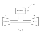
- FIG. 1 illustrates a typical gas turbine 10.
- the gas turbine 10 generally includes a compressor 12 at the front, one or more combustors 14 around the middle, and a turbine 16 at the rear.
- the compressor 12 and the turbine 16 typically share a common rotor.
- the compressor 12 pressurizes inlet air, which is then turned in direction or reverse flowed to the combustors 14 where it is used to cool the combustor and also to provide air to the combustion process.
- the combustors 14 inject fuel into the flow of compressed working fluid and ignite the mixture to produce combustion gases having a high temperature, pressure and velocity.
- the combustion gases exit the combustors 14 and flow to the turbine 16 where they expand to produce work.
- FIG. 2 is a cross-sectional view through the micromixer multi-tube assembly in a gas/liquid fuel nozzle.
- a concept of the preferred embodiments takes the no-atomizing-air liquid cartridge design and applies it to a premixing tube bundle sector, micromixer, head end.
- the fuel nozzle 20 includes a premixing tube bundle 22 including an array of mixing tubes 24.
- a fuel plenum 25 delivers fuel to the mixing tubes 24.
- a cartridge tube 26 is disposed within the fuel plenum 25, and a liquid fuel cartridge 28 is disposed in the cartridge tube 26.
- the liquid fuel cartridge 28 is spaced from the cartridge tube 26 to define an annulus 30.
- the cartridge tube 26 and the fuel plenum 25 are constructed in fluid communication such that gas fuel in the plenum 25 is injected into the annulus 30.
- the cartridge tube 26 includes a plurality of gas fuel injection holes 32 that allow gas fuel to be injected from the fuel plenum 25 to the annulus 30.
- the fuel plenum 25 includes a plurality of gas fuel extraction holes 34 that release gas fuel from the mixing tube(s).
- the gas fuel is injected radially inward into the annulus 30 to premix gas fuel and air prior to injection into the combustion chamber.
- the design allows the air in the liquid cartridge during gas only operation of the turbine to be premixed with gas fuel before entering the combustor, allowing the combustor to produce less NOx emissions, while operating on gas fuel.
- the amount of gas injection could be tailored, either passively with effective-flow area selection, or actively using another separate fuel circuit, to produce a fuel-air mixture that is the same, less than, or greater than the surrounding micromixer tubes. In a typical operation, the fuel/air in the annulus would be leaner than the surrounding mixing tubes.
- the annulus 30 may be designed to have swirled or non-swirled air to enhance the performance of the nozzle.
- a vane 36 may be disposed in the annulus 30 that serves to swirl air and gas-fuel prior to exiting the annulus 30.
- the resulting structure provides for added efficiency as no atomizing air subsystem is required for power, is less expensive, and achieves lower emissions by lower gas-fuel flame temperatures.
Landscapes
- Engineering & Computer Science (AREA)
- Chemical & Material Sciences (AREA)
- Combustion & Propulsion (AREA)
- Mechanical Engineering (AREA)
- General Engineering & Computer Science (AREA)
- Fuel-Injection Apparatus (AREA)
- Combustion Methods Of Internal-Combustion Engines (AREA)
- Nozzles (AREA)
Abstract
Description
- The invention relates generally to gas turbines and, more particularly, to a gas turbine operable in a dual fuel mode where a liquid cartridge air blast circuit is passively fueled for gas operation.
- Gas turbine engines typically include a compressor for compressing an incoming airflow. The airflow is mixed with fuel and ignited in a combustor for generating hot combustion gases. The combustion gases in turn flow to a turbine. The turbine extracts energy from the gases for driving a shaft. The shaft powers the compressor and generally another element such as an electrical generator.
- In some designs, the combustors operate with backup fuel such as liquid fuel. A liquid fuel cartridge is inserted through a micromixing fuel nozzle assembly upstream of a combustion zone. When the turbine is not running with liquid fuel, air is purged through the liquid cartridges. A problem with the existing design, however, is that the air in the liquid cartridges contributes to NOx production in the combustion zone, which is undesirable.
- It would be advantageous to address this problem by bleeding gas fuel into an annulus of the liquid cartridge to mix with air during gas only operation of the turbine.
- In an exemplary embodiment, a gas/liquid fuel nozzle assembly includes a premixing tube bundle having an array of mixing tubes, a fuel plenum to deliver fuel to the mixing tubes, a cartridge tube disposed within the fuel plenum, and a liquid fuel cartridge disposed in the cartridge tube. The liquid fuel cartridge is spaced from the cartridge tube to define an annulus. The cartridge tube and the fuel plenum are constructed in fluid communication such that gas fuel in the plenum is injected into the annulus.
- In another exemplary embodiment, a micromixer in a dual fuel gas turbine that delivers fuel and air to a combustor includes a premixing tube bundle including an array of mixing tubes; a fuel plenum to deliver fuel to the mixing tubes via a plurality of gas fuel extraction holes; a cartridge tube disposed within the plenum and including a plurality of gas fuel injection holes; and a liquid fuel cartridge disposed in the cartridge tube. Gas fuel in the plenum is injected via the gas fuel extraction holes and the gas fuel injection holes into an annulus between the liquid fuel cartridge and the cartridge tube.
- In yet another exemplary embodiment, a method of operating the dual fuel gas turbine includes the steps of (a) operating the dual fuel gas turbine in a gas fuel mode; (b) during step (a), flowing air through the liquid fuel cartridge and the annulus; and (c) during step (a), injecting gas fuel from the plenum into the annulus.
-
FIG. 1 is a simplified schematic of a gas turbine; and -
FIG. 2 is a cross section through a micromixer multi-tube assembly in a dual fuel nozzle. -
FIG. 1 illustrates atypical gas turbine 10. As shown, thegas turbine 10 generally includes acompressor 12 at the front, one ormore combustors 14 around the middle, and aturbine 16 at the rear. Thecompressor 12 and theturbine 16 typically share a common rotor. Thecompressor 12 pressurizes inlet air, which is then turned in direction or reverse flowed to thecombustors 14 where it is used to cool the combustor and also to provide air to the combustion process. Thecombustors 14 inject fuel into the flow of compressed working fluid and ignite the mixture to produce combustion gases having a high temperature, pressure and velocity. The combustion gases exit thecombustors 14 and flow to theturbine 16 where they expand to produce work. -
FIG. 2 is a cross-sectional view through the micromixer multi-tube assembly in a gas/liquid fuel nozzle. A concept of the preferred embodiments takes the no-atomizing-air liquid cartridge design and applies it to a premixing tube bundle sector, micromixer, head end. Thefuel nozzle 20 includes apremixing tube bundle 22 including an array ofmixing tubes 24. Afuel plenum 25 delivers fuel to themixing tubes 24. Acartridge tube 26 is disposed within thefuel plenum 25, and aliquid fuel cartridge 28 is disposed in thecartridge tube 26. Theliquid fuel cartridge 28 is spaced from thecartridge tube 26 to define anannulus 30. Thecartridge tube 26 and thefuel plenum 25 are constructed in fluid communication such that gas fuel in theplenum 25 is injected into theannulus 30. - In a preferred construction, the
cartridge tube 26 includes a plurality of gasfuel injection holes 32 that allow gas fuel to be injected from thefuel plenum 25 to theannulus 30. Thefuel plenum 25 includes a plurality of gasfuel extraction holes 34 that release gas fuel from the mixing tube(s). - As shown, the gas fuel is injected radially inward into the
annulus 30 to premix gas fuel and air prior to injection into the combustion chamber. The design allows the air in the liquid cartridge during gas only operation of the turbine to be premixed with gas fuel before entering the combustor, allowing the combustor to produce less NOx emissions, while operating on gas fuel. - The amount of gas injection could be tailored, either passively with effective-flow area selection, or actively using another separate fuel circuit, to produce a fuel-air mixture that is the same, less than, or greater than the surrounding micromixer tubes. In a typical operation, the fuel/air in the annulus would be leaner than the surrounding mixing tubes.
- The
annulus 30 may be designed to have swirled or non-swirled air to enhance the performance of the nozzle. In this context, avane 36 may be disposed in theannulus 30 that serves to swirl air and gas-fuel prior to exiting theannulus 30. - The resulting structure provides for added efficiency as no atomizing air subsystem is required for power, is less expensive, and achieves lower emissions by lower gas-fuel flame temperatures.
- While the invention has been described in connection with what is presently considered to be the most practical and preferred embodiments, it is to be understood that the invention is not to be limited to the disclosed embodiments, but on the contrary, is intended to cover various modifications and equivalent arrangements included within the scope of the appended claims.
- Various aspects and embodiments of the present invention are defined by the following numbered clauses:
- 1. A gas/liquid fuel nozzle assembly comprising:
- a premixing tube bundle including an array of mixing tubes;
- a fuel plenum that delivers fuel to the mixing tubes;
- a cartridge tube disposed within the plenum; and
- a liquid fuel cartridge disposed in the cartridge tube, the liquid fuel cartridge being spaced from the cartridge tube to define an annulus,
- wherein the cartridge tube and the fuel plenum are constructed in fluid communication such that gas fuel in the fuel plenum is injected into the annulus.
- 2. A gas/liquid fuel nozzle assembly according to clause 1, wherein the cartridge tube comprises a plurality of gas fuel injection holes that allow gas fuel to be injected from the fuel plenum to the annulus.
- 3. A gas/liquid fuel nozzle assembly according to any preceding clause, wherein the fuel plenum comprises a plurality of gas fuel extraction holes that release gas fuel from the mixing tube.
- 4. A gas/liquid fuel nozzle assembly according to any preceding clause, further comprising a vane disposed in the annulus, the vane swirling air and gas-fuel prior to exiting the annulus.
- 5. A gas/liquid fuel nozzle assembly according to any preceding clause, wherein an amount of gas fuel injected into the annulus is tailored.
- 6. A gas/liquid fuel nozzle assembly according to any preceding clause, wherein the amount of gas fuel injected into the annulus is tailored either passively with effective flow area selection or actively using a separate fuel circuit.
- 7. A micromixer in a dual fuel gas turbine that delivers fuel and air to a combustor, the micromixer comprising:
- a premixing tube bundle including an array of mixing tubes;
- a fuel plenum that delivers fuel to the mixing tubes, the fuel plenum including a plurality of gas fuel extraction holes;
- a cartridge tube disposed within the plenum, the cartridge tube including a plurality of gas fuel injection holes; and
- a liquid fuel cartridge disposed in the cartridge tube,
- wherein gas fuel in the plenum is injected via the gas fuel extraction holes and the gas fuel injection holes into an annulus between the liquid fuel cartridge and the cartridge tube.
- 8. A micromixer according to any preceding clause, further comprising a vane disposed in the annulus, the vane swirling air and gas fuel prior to exiting the annulus.
- 9. A micromixer according to any preceding clause, wherein an amount of gas fuel injected into the annulus is tailored.
- 10. A micromixer according to any preceding clause, wherein the amount of gas fuel injected into the annulus is tailored either passively with effective flow area selection or actively using a separate fuel circuit.
- 11. A method of operating a dual fuel gas turbine including a premixing tube bundle with an array of mixing tubes, a fuel plenum deliver fuel to the mixing tubes, a cartridge tube disposed within the fuel plenum, and a liquid fuel cartridge disposed in the cartridge tube and spaced from the cartridge tube to define an annulus, wherein the cartridge tube and the fuel plenum are constructed in fluid communication, the method comprising:
- (a) operating the dual fuel gas turbine in a gas fuel mode;
- (b) during step (a), flowing air through the liquid fuel cartridge and the annulus; and
- (c) during step (a), injecting gas fuel from the fuel plenum into the annulus.
- 12. A method according to any preceding clause, wherein the fuel plenum includes a plurality of fuel extraction holes, and wherein step (c) is practiced by extracting the gas fuel from the fuel plenum via the fuel extraction holes.
- 13. A method according to any preceding clause, wherein the cartridge tube includes a plurality of fuel injection holes, and wherein step (c) is further practiced by injection the gas fuel into the annulus via the fuel injection holes.
- 14. A method according to any preceding clause, further comprising imparting swirl to flow in the annulus.
- 15. A method according to any preceding clause, wherein step (c) is practiced by injecting the gas fuel radially inward into the annulus.
- 16. A method according to any preceding clause, further comprising operating the dual fuel gas turbine in a liquid mode, and in the liquid mode, preventing the gas fuel from being injected into the annulus.
- 17. A method according to any preceding clause, further comprising tailoring an amount of gas fuel injected from the fuel plenum into the annulus.
Claims (15)
- A gas/liquid fuel nozzle assembly comprising:a premixing tube bundle (22) including an array of mixing tubes (24);a fuel plenum (25) for delivering fuel to the mixing tubes;a cartridge tube (26) disposed within the plenum; anda liquid fuel cartridge (28) disposed in the cartridge tube, the liquid fuel cartridge being spaced from the cartridge tube to define an annulus (30),wherein the cartridge tube and the fuel plenum are constructed in fluid communication such that gas fuel in the fuel plenum is injectable into the annulus.
- A gas/liquid fuel nozzle assembly according to claim 1, wherein the cartridge tube (26) comprises a plurality of gas fuel injection holes (32) that allow gas fuel to be injected from the fuel plenum (25) to the annulus (30).
- A gas/liquid fuel nozzle assembly according to claim 2, wherein the fuel plenum (25) comprises a plurality of gas fuel extraction holes (34) for releasing gas fuel from the mixing tubes (24).
- A gas/liquid fuel nozzle assembly according to any of the preceding claims, further comprising a vane (36) disposed in the annulus (30), the vane operable to swirl air and gas-fuel prior to exiting the annulus.
- A gas/liquid fuel nozzle assembly according to any preceding clause, wherein an amount of gas fuel injected into the annulus (30) is tailored.
- A micromixer in a dual fuel gas turbine (10) that delivers fuel and air to a combustor (14), the micromixer comprising:a premixing tube bundle (22) including an array of mixing tubes (24);a fuel plenum (25) for delivering fuel to the mixing tubes, the fuel plenum including a plurality of gas fuel extraction holes (34);a cartridge tube (26) disposed within the plenum, the cartridge tube including a plurality of gas fuel injection holes (32); and a liquid fuel cartridge (28) disposed in the cartridge tube,wherein gas fuel in the plenum is injectable via the gas fuel extraction holes and the gas fuel injection holes into an annulus (30) between the liquid fuel cartridge and the cartridge tube.
- A micromixer according to claim 6, further comprising a vane (36) disposed in the annulus (30), the vane operable to swirl air and gas fuel prior to exiting the annulus.
- A micromixer according to either of claim 6 or 7, wherein an amount of gas fuel injected into the annulus (30) is tailored.
- A method of operating a dual fuel gas turbine (10) including a premixing tube bundle (22) with an array of mixing tubes (24), a fuel plenum (25) for delivering fuel to the mixing tubes, a cartridge tube (26) disposed within the fuel plenum, and a liquid fuel cartridge (28) disposed in the cartridge tube and spaced from the cartridge tube to define an annulus (30), wherein the cartridge tube and the fuel plenum are constructed in fluid communication, the method comprising:(a) operating the dual fuel gas turbine in a gas fuel mode;(b) during step (a), flowing air through the liquid fuel cartridge (28) and the annulus (30); and(c) during step (a), injecting gas fuel from the fuel plenum (25) into the annulus (30).
- A method according to claim 9, wherein the fuel plenum (25) includes a plurality of fuel extraction holes (34), and wherein step (c) is practiced by extracting the gas fuel from the fuel plenum via the fuel extraction holes.
- A method according to claim 10, wherein the cartridge tube (26) includes a plurality of fuel injection holes (32), and wherein step (c) is further practiced by injection of the gas fuel into the annulus (30) via the fuel injection holes.
- A method according to any of claims 9 to 11, further comprising imparting swirl to flow in the annulus (30).
- A method according to any of claims 9 to 12, wherein step (c) is practiced by injecting the gas fuel radially inward into the annulus (30).
- A method according to any of claims 9 to 13, further comprising operating the dual fuel gas turbine in a liquid mode, and in the liquid mode, preventing the gas fuel from being injected into the annulus (30).
- A method according to any of claims 9 to 14, further comprising tailoring an amount of gas fuel injected from the fuel plenum (25) into the annulus (30).
Applications Claiming Priority (1)
| Application Number | Priority Date | Filing Date | Title |
|---|---|---|---|
| US13/480,896 US9261279B2 (en) | 2012-05-25 | 2012-05-25 | Liquid cartridge with passively fueled premixed air blast circuit for gas operation |
Publications (3)
| Publication Number | Publication Date |
|---|---|
| EP2667099A2 true EP2667099A2 (en) | 2013-11-27 |
| EP2667099A3 EP2667099A3 (en) | 2017-09-20 |
| EP2667099B1 EP2667099B1 (en) | 2019-10-16 |
Family
ID=48607014
Family Applications (1)
| Application Number | Title | Priority Date | Filing Date |
|---|---|---|---|
| EP13169106.5A Active EP2667099B1 (en) | 2012-05-25 | 2013-05-24 | Liquid cartridge with passively fueled premixed air blast circuit for gas operation |
Country Status (5)
| Country | Link |
|---|---|
| US (1) | US9261279B2 (en) |
| EP (1) | EP2667099B1 (en) |
| JP (1) | JP6200692B2 (en) |
| CN (1) | CN103423772B (en) |
| RU (1) | RU2013123643A (en) |
Cited By (1)
| Publication number | Priority date | Publication date | Assignee | Title |
|---|---|---|---|---|
| KR102415892B1 (en) * | 2021-01-27 | 2022-06-30 | 두산에너빌리티 주식회사 | Micromixer and combustor having the same |
Families Citing this family (12)
| Publication number | Priority date | Publication date | Assignee | Title |
|---|---|---|---|---|
| US9435540B2 (en) | 2013-12-11 | 2016-09-06 | General Electric Company | Fuel injector with premix pilot nozzle |
| US9714767B2 (en) | 2014-11-26 | 2017-07-25 | General Electric Company | Premix fuel nozzle assembly |
| US10030869B2 (en) | 2014-11-26 | 2018-07-24 | General Electric Company | Premix fuel nozzle assembly |
| US9982892B2 (en) | 2015-04-16 | 2018-05-29 | General Electric Company | Fuel nozzle assembly including a pilot nozzle |
| US9803867B2 (en) | 2015-04-21 | 2017-10-31 | General Electric Company | Premix pilot nozzle |
| US10215415B2 (en) | 2015-09-23 | 2019-02-26 | General Electric Company | Premix fuel nozzle assembly cartridge |
| US10415833B2 (en) | 2017-02-16 | 2019-09-17 | General Electric Company | Premixer for gas turbine combustor |
| US10982593B2 (en) | 2017-06-16 | 2021-04-20 | General Electric Company | System and method for combusting liquid fuel in a gas turbine combustor with staged combustion |
| US10655858B2 (en) | 2017-06-16 | 2020-05-19 | General Electric Company | Cooling of liquid fuel cartridge in gas turbine combustor head end |
| US10578306B2 (en) | 2017-06-16 | 2020-03-03 | General Electric Company | Liquid fuel cartridge unit for gas turbine combustor and method of assembly |
| US10767866B2 (en) | 2018-07-11 | 2020-09-08 | General Electric Company | Micromixer for use with liquid fuel |
| CN112856483B (en) * | 2021-01-12 | 2022-07-15 | 哈尔滨工业大学 | A humidified micro-mix burner |
Family Cites Families (26)
| Publication number | Priority date | Publication date | Assignee | Title |
|---|---|---|---|---|
| US4262482A (en) * | 1977-11-17 | 1981-04-21 | Roffe Gerald A | Apparatus for the premixed gas phase combustion of liquid fuels |
| DE3361535D1 (en) * | 1982-05-28 | 1986-01-30 | Bbc Brown Boveri & Cie | Gas turbine combustion chamber and method of operating it |
| US5361586A (en) * | 1993-04-15 | 1994-11-08 | Westinghouse Electric Corporation | Gas turbine ultra low NOx combustor |
| DE4326802A1 (en) | 1993-08-10 | 1995-02-16 | Abb Management Ag | Fuel lance for liquid and / or gaseous fuels and process for their operation |
| US5836164A (en) * | 1995-01-30 | 1998-11-17 | Hitachi, Ltd. | Gas turbine combustor |
| US5713205A (en) | 1996-08-06 | 1998-02-03 | General Electric Co. | Air atomized discrete jet liquid fuel injector and method |
| GB2373043B (en) * | 2001-03-09 | 2004-09-22 | Alstom Power Nv | Fuel injector |
| US6539724B2 (en) * | 2001-03-30 | 2003-04-01 | Delavan Inc | Airblast fuel atomization system |
| EP1456583B1 (en) * | 2001-12-20 | 2007-10-10 | Alstom Technology Ltd | Method for injecting a fuel/air mixture in a combustion chamber |
| US6609380B2 (en) | 2001-12-28 | 2003-08-26 | General Electric Company | Liquid fuel nozzle apparatus with passive protective purge |
| US7165405B2 (en) * | 2002-07-15 | 2007-01-23 | Power Systems Mfg. Llc | Fully premixed secondary fuel nozzle with dual fuel capability |
| US7546735B2 (en) * | 2004-10-14 | 2009-06-16 | General Electric Company | Low-cost dual-fuel combustor and related method |
| JP4728176B2 (en) * | 2005-06-24 | 2011-07-20 | 株式会社日立製作所 | Burner, gas turbine combustor and burner cooling method |
| US8112999B2 (en) * | 2008-08-05 | 2012-02-14 | General Electric Company | Turbomachine injection nozzle including a coolant delivery system |
| US9140454B2 (en) * | 2009-01-23 | 2015-09-22 | General Electric Company | Bundled multi-tube nozzle for a turbomachine |
| US8205452B2 (en) * | 2009-02-02 | 2012-06-26 | General Electric Company | Apparatus for fuel injection in a turbine engine |
| US8157189B2 (en) * | 2009-04-03 | 2012-04-17 | General Electric Company | Premixing direct injector |
| US20110016866A1 (en) * | 2009-07-22 | 2011-01-27 | General Electric Company | Apparatus for fuel injection in a turbine engine |
| US8276385B2 (en) * | 2009-10-08 | 2012-10-02 | General Electric Company | Staged multi-tube premixing injector |
| US8613197B2 (en) * | 2010-08-05 | 2013-12-24 | General Electric Company | Turbine combustor with fuel nozzles having inner and outer fuel circuits |
| US8800289B2 (en) * | 2010-09-08 | 2014-08-12 | General Electric Company | Apparatus and method for mixing fuel in a gas turbine nozzle |
| CN202048572U (en) * | 2011-01-19 | 2011-11-23 | 兰州泰得燃烧设备工程有限公司 | Industrial gas burner |
| US9010083B2 (en) * | 2011-02-03 | 2015-04-21 | General Electric Company | Apparatus for mixing fuel in a gas turbine |
| US20130036743A1 (en) * | 2011-08-08 | 2013-02-14 | General Electric Company | Turbomachine combustor assembly |
| US8801428B2 (en) * | 2011-10-04 | 2014-08-12 | General Electric Company | Combustor and method for supplying fuel to a combustor |
| US8550809B2 (en) * | 2011-10-20 | 2013-10-08 | General Electric Company | Combustor and method for conditioning flow through a combustor |
-
2012
- 2012-05-25 US US13/480,896 patent/US9261279B2/en active Active
-
2013
- 2013-05-22 JP JP2013107543A patent/JP6200692B2/en active Active
- 2013-05-23 RU RU2013123643/06A patent/RU2013123643A/en not_active Application Discontinuation
- 2013-05-24 EP EP13169106.5A patent/EP2667099B1/en active Active
- 2013-05-24 CN CN201310195935.5A patent/CN103423772B/en active Active
Non-Patent Citations (1)
| Title |
|---|
| None |
Cited By (2)
| Publication number | Priority date | Publication date | Assignee | Title |
|---|---|---|---|---|
| KR102415892B1 (en) * | 2021-01-27 | 2022-06-30 | 두산에너빌리티 주식회사 | Micromixer and combustor having the same |
| US12060996B2 (en) | 2021-01-27 | 2024-08-13 | Doosan Enerbility Co., Ltd. | Micromixer and combustor having the same |
Also Published As
| Publication number | Publication date |
|---|---|
| EP2667099B1 (en) | 2019-10-16 |
| JP6200692B2 (en) | 2017-09-20 |
| JP2013245935A (en) | 2013-12-09 |
| US9261279B2 (en) | 2016-02-16 |
| RU2013123643A (en) | 2014-11-27 |
| US20130312422A1 (en) | 2013-11-28 |
| EP2667099A3 (en) | 2017-09-20 |
| CN103423772B (en) | 2016-12-07 |
| CN103423772A (en) | 2013-12-04 |
Similar Documents
| Publication | Publication Date | Title |
|---|---|---|
| EP2667099B1 (en) | Liquid cartridge with passively fueled premixed air blast circuit for gas operation | |
| EP2481982B2 (en) | Mixer assembly for a gas turbine engine | |
| CN103822228B (en) | Fuel nozzle and its assemble method | |
| US8783008B2 (en) | Gas turbine reheat combustor including a fuel injector for delivering fuel into a gas mixture together with cooling air previously used for convectively cooling the reheat combustor | |
| JP6266211B2 (en) | Combustor assembly with vortex retention cavities | |
| JP5393745B2 (en) | Gas turbine combustor | |
| CN107923620B (en) | System and method for multi-fuel premixing nozzle with integral liquid injector/evaporator | |
| EP2525149A2 (en) | Combustor | |
| US20140144142A1 (en) | Fuel nozzle for use in a turbine engine and method of assembly | |
| JP2014132214A (en) | Fuel injector for supplying fuel to combustor | |
| EP3102877B1 (en) | Combustor | |
| KR102071324B1 (en) | Nozzle for combustor, combustor, and gas turbine including the same | |
| KR102083915B1 (en) | Nozzle for combustor, combustor, and gas turbine including the same | |
| EP2664854A2 (en) | Secondary combustion system | |
| JP2013217635A (en) | Diffusion combustor fuel nozzle | |
| KR102070908B1 (en) | Nozzle for combustor, combustor, and gas turbine including the same | |
| US20140144150A1 (en) | Fuel nozzle for use in a turbine engine and method of assembly | |
| US20160018110A1 (en) | Axially staged gas turbine combustor with interstage premixer | |
| CN116293796A (en) | burner with igniter | |
| KR102021129B1 (en) | Fuel nozzle, combustor and gas turbine having the same | |
| EP2629015A2 (en) | Outer fuel nozzle inlet flow conditioner interface to end cap | |
| EP4283197A2 (en) | Combustor | |
| KR20190133129A (en) | Combustor and gas turbine comprising the same |
Legal Events
| Date | Code | Title | Description |
|---|---|---|---|
| PUAI | Public reference made under article 153(3) epc to a published international application that has entered the european phase |
Free format text: ORIGINAL CODE: 0009012 |
|
| AK | Designated contracting states |
Kind code of ref document: A2 Designated state(s): AL AT BE BG CH CY CZ DE DK EE ES FI FR GB GR HR HU IE IS IT LI LT LU LV MC MK MT NL NO PL PT RO RS SE SI SK SM TR |
|
| AX | Request for extension of the european patent |
Extension state: BA ME |
|
| PUAL | Search report despatched |
Free format text: ORIGINAL CODE: 0009013 |
|
| RIC1 | Information provided on ipc code assigned before grant |
Ipc: F23R 3/36 20060101ALI20170809BHEP Ipc: F23R 3/28 20060101AFI20170809BHEP Ipc: F23D 14/62 20060101ALI20170809BHEP |
|
| AK | Designated contracting states |
Kind code of ref document: A3 Designated state(s): AL AT BE BG CH CY CZ DE DK EE ES FI FR GB GR HR HU IE IS IT LI LT LU LV MC MK MT NL NO PL PT RO RS SE SI SK SM TR |
|
| AX | Request for extension of the european patent |
Extension state: BA ME |
|
| STAA | Information on the status of an ep patent application or granted ep patent |
Free format text: STATUS: REQUEST FOR EXAMINATION WAS MADE |
|
| 17P | Request for examination filed |
Effective date: 20180320 |
|
| RBV | Designated contracting states (corrected) |
Designated state(s): AL AT BE BG CH CY CZ DE DK EE ES FI FR GB GR HR HU IE IS IT LI LT LU LV MC MK MT NL NO PL PT RO RS SE SI SK SM TR |
|
| STAA | Information on the status of an ep patent application or granted ep patent |
Free format text: STATUS: EXAMINATION IS IN PROGRESS |
|
| 17Q | First examination report despatched |
Effective date: 20180914 |
|
| GRAP | Despatch of communication of intention to grant a patent |
Free format text: ORIGINAL CODE: EPIDOSNIGR1 |
|
| STAA | Information on the status of an ep patent application or granted ep patent |
Free format text: STATUS: GRANT OF PATENT IS INTENDED |
|
| INTG | Intention to grant announced |
Effective date: 20190425 |
|
| GRAS | Grant fee paid |
Free format text: ORIGINAL CODE: EPIDOSNIGR3 |
|
| GRAA | (expected) grant |
Free format text: ORIGINAL CODE: 0009210 |
|
| STAA | Information on the status of an ep patent application or granted ep patent |
Free format text: STATUS: THE PATENT HAS BEEN GRANTED |
|
| AK | Designated contracting states |
Kind code of ref document: B1 Designated state(s): AL AT BE BG CH CY CZ DE DK EE ES FI FR GB GR HR HU IE IS IT LI LT LU LV MC MK MT NL NO PL PT RO RS SE SI SK SM TR |
|
| REG | Reference to a national code |
Ref country code: GB Ref legal event code: FG4D |
|
| REG | Reference to a national code |
Ref country code: CH Ref legal event code: EP |
|
| REG | Reference to a national code |
Ref country code: DE Ref legal event code: R096 Ref document number: 602013061716 Country of ref document: DE |
|
| REG | Reference to a national code |
Ref country code: IE Ref legal event code: FG4D |
|
| REG | Reference to a national code |
Ref country code: AT Ref legal event code: REF Ref document number: 1191651 Country of ref document: AT Kind code of ref document: T Effective date: 20191115 |
|
| REG | Reference to a national code |
Ref country code: NL Ref legal event code: MP Effective date: 20191016 |
|
| REG | Reference to a national code |
Ref country code: LT Ref legal event code: MG4D |
|
| REG | Reference to a national code |
Ref country code: AT Ref legal event code: MK05 Ref document number: 1191651 Country of ref document: AT Kind code of ref document: T Effective date: 20191016 |
|
| PG25 | Lapsed in a contracting state [announced via postgrant information from national office to epo] |
Ref country code: PT Free format text: LAPSE BECAUSE OF FAILURE TO SUBMIT A TRANSLATION OF THE DESCRIPTION OR TO PAY THE FEE WITHIN THE PRESCRIBED TIME-LIMIT Effective date: 20200217 Ref country code: ES Free format text: LAPSE BECAUSE OF FAILURE TO SUBMIT A TRANSLATION OF THE DESCRIPTION OR TO PAY THE FEE WITHIN THE PRESCRIBED TIME-LIMIT Effective date: 20191016 Ref country code: FI Free format text: LAPSE BECAUSE OF FAILURE TO SUBMIT A TRANSLATION OF THE DESCRIPTION OR TO PAY THE FEE WITHIN THE PRESCRIBED TIME-LIMIT Effective date: 20191016 Ref country code: NO Free format text: LAPSE BECAUSE OF FAILURE TO SUBMIT A TRANSLATION OF THE DESCRIPTION OR TO PAY THE FEE WITHIN THE PRESCRIBED TIME-LIMIT Effective date: 20200116 Ref country code: LV Free format text: LAPSE BECAUSE OF FAILURE TO SUBMIT A TRANSLATION OF THE DESCRIPTION OR TO PAY THE FEE WITHIN THE PRESCRIBED TIME-LIMIT Effective date: 20191016 Ref country code: SE Free format text: LAPSE BECAUSE OF FAILURE TO SUBMIT A TRANSLATION OF THE DESCRIPTION OR TO PAY THE FEE WITHIN THE PRESCRIBED TIME-LIMIT Effective date: 20191016 Ref country code: LT Free format text: LAPSE BECAUSE OF FAILURE TO SUBMIT A TRANSLATION OF THE DESCRIPTION OR TO PAY THE FEE WITHIN THE PRESCRIBED TIME-LIMIT Effective date: 20191016 Ref country code: NL Free format text: LAPSE BECAUSE OF FAILURE TO SUBMIT A TRANSLATION OF THE DESCRIPTION OR TO PAY THE FEE WITHIN THE PRESCRIBED TIME-LIMIT Effective date: 20191016 Ref country code: PL Free format text: LAPSE BECAUSE OF FAILURE TO SUBMIT A TRANSLATION OF THE DESCRIPTION OR TO PAY THE FEE WITHIN THE PRESCRIBED TIME-LIMIT Effective date: 20191016 Ref country code: GR Free format text: LAPSE BECAUSE OF FAILURE TO SUBMIT A TRANSLATION OF THE DESCRIPTION OR TO PAY THE FEE WITHIN THE PRESCRIBED TIME-LIMIT Effective date: 20200117 Ref country code: BG Free format text: LAPSE BECAUSE OF FAILURE TO SUBMIT A TRANSLATION OF THE DESCRIPTION OR TO PAY THE FEE WITHIN THE PRESCRIBED TIME-LIMIT Effective date: 20200116 Ref country code: AT Free format text: LAPSE BECAUSE OF FAILURE TO SUBMIT A TRANSLATION OF THE DESCRIPTION OR TO PAY THE FEE WITHIN THE PRESCRIBED TIME-LIMIT Effective date: 20191016 |
|
| PG25 | Lapsed in a contracting state [announced via postgrant information from national office to epo] |
Ref country code: IS Free format text: LAPSE BECAUSE OF FAILURE TO SUBMIT A TRANSLATION OF THE DESCRIPTION OR TO PAY THE FEE WITHIN THE PRESCRIBED TIME-LIMIT Effective date: 20200224 Ref country code: HR Free format text: LAPSE BECAUSE OF FAILURE TO SUBMIT A TRANSLATION OF THE DESCRIPTION OR TO PAY THE FEE WITHIN THE PRESCRIBED TIME-LIMIT Effective date: 20191016 Ref country code: RS Free format text: LAPSE BECAUSE OF FAILURE TO SUBMIT A TRANSLATION OF THE DESCRIPTION OR TO PAY THE FEE WITHIN THE PRESCRIBED TIME-LIMIT Effective date: 20191016 |
|
| PG25 | Lapsed in a contracting state [announced via postgrant information from national office to epo] |
Ref country code: AL Free format text: LAPSE BECAUSE OF FAILURE TO SUBMIT A TRANSLATION OF THE DESCRIPTION OR TO PAY THE FEE WITHIN THE PRESCRIBED TIME-LIMIT Effective date: 20191016 |
|
| REG | Reference to a national code |
Ref country code: DE Ref legal event code: R097 Ref document number: 602013061716 Country of ref document: DE |
|
| PG2D | Information on lapse in contracting state deleted |
Ref country code: IS |
|
| PG25 | Lapsed in a contracting state [announced via postgrant information from national office to epo] |
Ref country code: EE Free format text: LAPSE BECAUSE OF FAILURE TO SUBMIT A TRANSLATION OF THE DESCRIPTION OR TO PAY THE FEE WITHIN THE PRESCRIBED TIME-LIMIT Effective date: 20191016 Ref country code: DK Free format text: LAPSE BECAUSE OF FAILURE TO SUBMIT A TRANSLATION OF THE DESCRIPTION OR TO PAY THE FEE WITHIN THE PRESCRIBED TIME-LIMIT Effective date: 20191016 Ref country code: CZ Free format text: LAPSE BECAUSE OF FAILURE TO SUBMIT A TRANSLATION OF THE DESCRIPTION OR TO PAY THE FEE WITHIN THE PRESCRIBED TIME-LIMIT Effective date: 20191016 Ref country code: RO Free format text: LAPSE BECAUSE OF FAILURE TO SUBMIT A TRANSLATION OF THE DESCRIPTION OR TO PAY THE FEE WITHIN THE PRESCRIBED TIME-LIMIT Effective date: 20191016 Ref country code: IS Free format text: LAPSE BECAUSE OF FAILURE TO SUBMIT A TRANSLATION OF THE DESCRIPTION OR TO PAY THE FEE WITHIN THE PRESCRIBED TIME-LIMIT Effective date: 20200216 |
|
| PLBE | No opposition filed within time limit |
Free format text: ORIGINAL CODE: 0009261 |
|
| STAA | Information on the status of an ep patent application or granted ep patent |
Free format text: STATUS: NO OPPOSITION FILED WITHIN TIME LIMIT |
|
| PG25 | Lapsed in a contracting state [announced via postgrant information from national office to epo] |
Ref country code: SM Free format text: LAPSE BECAUSE OF FAILURE TO SUBMIT A TRANSLATION OF THE DESCRIPTION OR TO PAY THE FEE WITHIN THE PRESCRIBED TIME-LIMIT Effective date: 20191016 Ref country code: IT Free format text: LAPSE BECAUSE OF FAILURE TO SUBMIT A TRANSLATION OF THE DESCRIPTION OR TO PAY THE FEE WITHIN THE PRESCRIBED TIME-LIMIT Effective date: 20191016 Ref country code: SK Free format text: LAPSE BECAUSE OF FAILURE TO SUBMIT A TRANSLATION OF THE DESCRIPTION OR TO PAY THE FEE WITHIN THE PRESCRIBED TIME-LIMIT Effective date: 20191016 |
|
| 26N | No opposition filed |
Effective date: 20200717 |
|
| PG25 | Lapsed in a contracting state [announced via postgrant information from national office to epo] |
Ref country code: SI Free format text: LAPSE BECAUSE OF FAILURE TO SUBMIT A TRANSLATION OF THE DESCRIPTION OR TO PAY THE FEE WITHIN THE PRESCRIBED TIME-LIMIT Effective date: 20191016 |
|
| PG25 | Lapsed in a contracting state [announced via postgrant information from national office to epo] |
Ref country code: MC Free format text: LAPSE BECAUSE OF FAILURE TO SUBMIT A TRANSLATION OF THE DESCRIPTION OR TO PAY THE FEE WITHIN THE PRESCRIBED TIME-LIMIT Effective date: 20191016 Ref country code: LI Free format text: LAPSE BECAUSE OF NON-PAYMENT OF DUE FEES Effective date: 20200531 Ref country code: CH Free format text: LAPSE BECAUSE OF NON-PAYMENT OF DUE FEES Effective date: 20200531 |
|
| REG | Reference to a national code |
Ref country code: BE Ref legal event code: MM Effective date: 20200531 |
|
| GBPC | Gb: european patent ceased through non-payment of renewal fee |
Effective date: 20200524 |
|
| PG25 | Lapsed in a contracting state [announced via postgrant information from national office to epo] |
Ref country code: LU Free format text: LAPSE BECAUSE OF NON-PAYMENT OF DUE FEES Effective date: 20200524 |
|
| PG25 | Lapsed in a contracting state [announced via postgrant information from national office to epo] |
Ref country code: IE Free format text: LAPSE BECAUSE OF NON-PAYMENT OF DUE FEES Effective date: 20200524 Ref country code: GB Free format text: LAPSE BECAUSE OF NON-PAYMENT OF DUE FEES Effective date: 20200524 Ref country code: FR Free format text: LAPSE BECAUSE OF NON-PAYMENT OF DUE FEES Effective date: 20200531 |
|
| PG25 | Lapsed in a contracting state [announced via postgrant information from national office to epo] |
Ref country code: BE Free format text: LAPSE BECAUSE OF NON-PAYMENT OF DUE FEES Effective date: 20200531 |
|
| PG25 | Lapsed in a contracting state [announced via postgrant information from national office to epo] |
Ref country code: TR Free format text: LAPSE BECAUSE OF FAILURE TO SUBMIT A TRANSLATION OF THE DESCRIPTION OR TO PAY THE FEE WITHIN THE PRESCRIBED TIME-LIMIT Effective date: 20191016 Ref country code: MT Free format text: LAPSE BECAUSE OF FAILURE TO SUBMIT A TRANSLATION OF THE DESCRIPTION OR TO PAY THE FEE WITHIN THE PRESCRIBED TIME-LIMIT Effective date: 20191016 Ref country code: CY Free format text: LAPSE BECAUSE OF FAILURE TO SUBMIT A TRANSLATION OF THE DESCRIPTION OR TO PAY THE FEE WITHIN THE PRESCRIBED TIME-LIMIT Effective date: 20191016 |
|
| PG25 | Lapsed in a contracting state [announced via postgrant information from national office to epo] |
Ref country code: MK Free format text: LAPSE BECAUSE OF FAILURE TO SUBMIT A TRANSLATION OF THE DESCRIPTION OR TO PAY THE FEE WITHIN THE PRESCRIBED TIME-LIMIT Effective date: 20191016 |
|
| REG | Reference to a national code |
Ref country code: DE Ref legal event code: R082 Ref document number: 602013061716 Country of ref document: DE Ref country code: DE Ref legal event code: R081 Ref document number: 602013061716 Country of ref document: DE Owner name: GENERAL ELECTRIC TECHNOLOGY GMBH, CH Free format text: FORMER OWNER: GENERAL ELECTRIC COMPANY, SCHENECTADY, NY, US |
|
| PGFP | Annual fee paid to national office [announced via postgrant information from national office to epo] |
Ref country code: DE Payment date: 20250423 Year of fee payment: 13 |