EP2667083A1 - Lighting device with smooth outer appearance - Google Patents
Lighting device with smooth outer appearance Download PDFInfo
- Publication number
- EP2667083A1 EP2667083A1 EP12168673.7A EP12168673A EP2667083A1 EP 2667083 A1 EP2667083 A1 EP 2667083A1 EP 12168673 A EP12168673 A EP 12168673A EP 2667083 A1 EP2667083 A1 EP 2667083A1
- Authority
- EP
- European Patent Office
- Prior art keywords
- lighting device
- heat sink
- opening
- protrusion
- sink component
- Prior art date
- Legal status (The legal status is an assumption and is not a legal conclusion. Google has not performed a legal analysis and makes no representation as to the accuracy of the status listed.)
- Withdrawn
Links
- 239000004020 conductor Substances 0.000 claims description 2
- 239000003570 air Substances 0.000 description 48
- 238000001816 cooling Methods 0.000 description 8
- 230000000694 effects Effects 0.000 description 7
- 239000012080 ambient air Substances 0.000 description 4
- 230000017525 heat dissipation Effects 0.000 description 4
- 229910052751 metal Inorganic materials 0.000 description 3
- 239000002184 metal Substances 0.000 description 3
- 229910052782 aluminium Inorganic materials 0.000 description 2
- XAGFODPZIPBFFR-UHFFFAOYSA-N aluminium Chemical compound [Al] XAGFODPZIPBFFR-UHFFFAOYSA-N 0.000 description 2
- 238000004519 manufacturing process Methods 0.000 description 2
- 238000000034 method Methods 0.000 description 2
- 230000003287 optical effect Effects 0.000 description 2
- 230000005855 radiation Effects 0.000 description 2
- 239000002994 raw material Substances 0.000 description 2
- 230000008878 coupling Effects 0.000 description 1
- 238000010168 coupling process Methods 0.000 description 1
- 238000005859 coupling reaction Methods 0.000 description 1
- 230000007423 decrease Effects 0.000 description 1
- 230000003247 decreasing effect Effects 0.000 description 1
- 238000004512 die casting Methods 0.000 description 1
- 238000009826 distribution Methods 0.000 description 1
- 239000000945 filler Substances 0.000 description 1
- 239000012467 final product Substances 0.000 description 1
- 239000003292 glue Substances 0.000 description 1
- 229910052736 halogen Inorganic materials 0.000 description 1
- 150000002367 halogens Chemical class 0.000 description 1
- 238000002347 injection Methods 0.000 description 1
- 239000007924 injection Substances 0.000 description 1
- 238000012986 modification Methods 0.000 description 1
- 230000004048 modification Effects 0.000 description 1
- 238000000465 moulding Methods 0.000 description 1
Images



Classifications
-
- F—MECHANICAL ENGINEERING; LIGHTING; HEATING; WEAPONS; BLASTING
- F21—LIGHTING
- F21V—FUNCTIONAL FEATURES OR DETAILS OF LIGHTING DEVICES OR SYSTEMS THEREOF; STRUCTURAL COMBINATIONS OF LIGHTING DEVICES WITH OTHER ARTICLES, NOT OTHERWISE PROVIDED FOR
- F21V29/00—Protecting lighting devices from thermal damage; Cooling or heating arrangements specially adapted for lighting devices or systems
- F21V29/50—Cooling arrangements
- F21V29/70—Cooling arrangements characterised by passive heat-dissipating elements, e.g. heat-sinks
- F21V29/83—Cooling arrangements characterised by passive heat-dissipating elements, e.g. heat-sinks the elements having apertures, ducts or channels, e.g. heat radiation holes
-
- F—MECHANICAL ENGINEERING; LIGHTING; HEATING; WEAPONS; BLASTING
- F21—LIGHTING
- F21K—NON-ELECTRIC LIGHT SOURCES USING LUMINESCENCE; LIGHT SOURCES USING ELECTROCHEMILUMINESCENCE; LIGHT SOURCES USING CHARGES OF COMBUSTIBLE MATERIAL; LIGHT SOURCES USING SEMICONDUCTOR DEVICES AS LIGHT-GENERATING ELEMENTS; LIGHT SOURCES NOT OTHERWISE PROVIDED FOR
- F21K9/00—Light sources using semiconductor devices as light-generating elements, e.g. using light-emitting diodes [LED] or lasers
- F21K9/20—Light sources comprising attachment means
- F21K9/23—Retrofit light sources for lighting devices with a single fitting for each light source, e.g. for substitution of incandescent lamps with bayonet or threaded fittings
- F21K9/233—Retrofit light sources for lighting devices with a single fitting for each light source, e.g. for substitution of incandescent lamps with bayonet or threaded fittings specially adapted for generating a spot light distribution, e.g. for substitution of reflector lamps
-
- F—MECHANICAL ENGINEERING; LIGHTING; HEATING; WEAPONS; BLASTING
- F21—LIGHTING
- F21Y—INDEXING SCHEME ASSOCIATED WITH SUBCLASSES F21K, F21L, F21S and F21V, RELATING TO THE FORM OR THE KIND OF THE LIGHT SOURCES OR OF THE COLOUR OF THE LIGHT EMITTED
- F21Y2115/00—Light-generating elements of semiconductor light sources
- F21Y2115/10—Light-emitting diodes [LED]
Definitions
- the invention relates generally to a lighting device, and more specifically to a lighting device or a lamp bulb with a smooth outer appearance.
- the invention also relates to a luminaire with a lamp bulb having a smooth outer appearance.
- a lighting device comprises a heat sink equipped with fins, for example back-reflecting lamp bulbs of type PAR, MR, BR, GU, etc.
- PAR parabolic aluminized reflector.
- MR means multifaceted reflector.
- BR means bulged reflector, and
- GUI refers to a U-shaped lamp with a plug-in lamp base.
- the light sources of the lamps include conventional halogen filaments or LED light sources.
- heat sinks are made of die casting metal, such as aluminum, with high manufacturing and raw material costs. Further, for aesthetic reasons, a non-technical appearance without a visible cooling structure is desired. If the heat sink structure is hidden behind a smooth outer surface, airflow through the cooling structure is preferred for improved thermal performance, which requires inlet and outlet openings. For the desired look-and-feel, these openings should be small. However, a small channel has a high airflow resistance, reducing the cooling performance of the heat sink structure. Since the cooling performance is mainly determined by the amount of air that flows through the cooling structure, also referred to as internal channel, this will reduce the cooling performance of the heat sink.
- an embodiment of a lighting device comprising: at least one light source; a heat sink component, having a bottom and a side wall extending from the bottom, wherein the bottom comprises a protrusion, and wherein the at least one light source thermally contacts the protrusion of the heat sink component; and a cover provided on the sidewall opposite to the bottom, thereby defining an air chamber between the cover, the side wall, the bottom and the protrusion.
- the protrusion provides an increased surface area of the heat sink component, leading to improved thermal properties of the heat sink and furthermore it provides a part of the enclosure of the air chamber.
- the width or diameter of the protrusion is the same as the width or diameter of the bottom, and hence the air chamber is enclosed by the protrusion, the side wall and the cover, because in this case the total area of the bottom is the protrusion.
- the side wall effectively extends from the protrusion.
- the cover is of a thermally conductive material which thermally contacts the side wall of the heat sink component.
- the cover comprises a recess which accommodates the at least one light source, and the recess thermally contacts the protrusion. In this way an additional thermal contact between the at least one light source and the heat sink component is provided in a convenient and simple way.
- a part of the cover may comprise a light exit window which may comprise an optical element, such as diffuser, a lens, etc.
- the protrusion has a side surface and a top surface, and the side surface forms a portion of the air chamber.
- the top surface of the protrusion does not form a portion of the air chamber.
- the side surface of the protrusion is part of the enclosure of the air chamber, together with the side walls of the heat component, the cover and a part of the bottom.
- the air chamber is defined and enclosed by the side surface of the protrusion, the side wall of the heat sink component and the cover.
- the cover comprises a first opening
- the heat sink component comprises a second opening
- the air chamber forms a channel between the first opening and the second opening to allow a flow of air between the first and second opening or vice versa.
- the protrusion provides an increased air flow cooling area of the heat sink component with respect to the state of the art in which no protrusion is defined.
- a cross section of the channel is larger than at least one of the first opening and the second opening.
- the bottom of the heat sink component is substantially circular and the protrusion is also substantially circular.
- the side wall also will have a substantially circular cross-section and also the cover will be substantially circular.
- the protrusion encompasses at least a part of an electronic component.
- the electronic component drives the at least one light source.
- space is saved by using the protrusion to enclose at least a part of the electronic component.
- the electronic component thus is not part of the air chamber but is situated outside the air chamber in another chamber between the protrusion of the heat sink component and a base of a lamp which comprises the lighting device.
- electrical contacts are provided between the electronic component and the at least one light source via through holes in the heat sink component.
- the cover is additionally mechanically attached to the protrusion, next to the mechanical attachment (and thermal connection) to the side wall of the heat sink component. Furthermore, the air can flow alongside the protrusion, which further improves the thermal performance of the lighting device.
- the side wall of the heat sink component has the shape of the side walls of a cup.
- the heat sink component and optionally also the cover can be made of sheet metal, such as aluminum plates, using a low-cost metal stretching process, such as deep drawing.
- the heat sink component and optionally also the cover can be made of plastic, using a stretching or injection/molding process. Compared to the conventional heavy die-cast heat sink, the cost of both raw material and manufacturing can be decreased, and the weight of the final product can be reduced.
- the cover comprises a rim at its outer periphery, and the first opening comprises a plurality of holes near the rim.
- the rim provides a mechanical attachment to the side wall.
- the heat sink component comprises a first and a second opening
- the air chamber forms a channel between the first opening and the second opening to allow a flow of air between the first and second opening or vice versa
- the first opening is a slit in the side wall of the heat sink component.
- the first opening is thus designed as holes in the cover or a hardly visible narrow slit in the side wall, resulting in an unobtrusive opening in the main view of the lighting device in the form of a lamp bulb. This may provide an ornamental effect to the bulb.
- the second opening of the lighting device preferably comprises a plurality of holes in the bottom of the heat sink component between the protrusion and the side wall of the heat sink component. This provides an unobtrusive, hardly visible opening in the main view of the lighting device in the form of a lamp bulb with an ornamental effect.
- the side wall of the heat sink component has an intact smooth exposed surface, without holes, slots or fins, which provides an ornamental effect in the main view of the lighting device in the form of a lamp bulb.
- the exposed surface has a relatively good heat dissipation capacity.
- the second opening comprises a plurality of holes disposed in the side wall of the heat sink component adjacent to the bottom of the heat sink component.
- the heat sink component and the cover are thermally coupled at least through engagement between a bottom portion of a recess in the cover and a top surface portion of the protrusion of the heat sink component.
- the heat generated by the light source and/or the electronic driving component can be conducted via the heat sink component and the cover and transported to the surrounding air via the exposed surfaces.
- the recess of the cover can further comprise a reflector.
- the at least one light source comprises a LED or an array of LEDs, and the lighting device can be a back-reflecting lamp bulb of type GU, MR, BR or PAR, such as GU10, MR16, BR30, BR40, R20, PAR38, PAR30L, PAR30S, PAR20, etc.
- a luminaire which comprises a lighting device or lamp bulb according to the first aspect of the invention with a smooth outer appearance.
- FIG. 1 shows a PAR lamp 100 with LEDs or a LED array representing a light source 101 mounted in the front end opposite to the base 109.
- the light source 101 is thermally coupled to a cover 103 and a heat sink component 104.
- the cover 103 may act as an additional heat sink component and is thermally coupled to the heat sink component 104 at least along its outer periphery.
- the cover 103 has a recess 1031 for accommodating the light source 101.
- the light source 101 is provided on the heat sink component 104, for example on the bottom part of the recess 1031, and the cover 103 comprises a light exit window where the light from the light source 101 can exit.
- the heat sink component 104 is, in this case, cup-shaped, and has a side wall 1044 and a bottom 1043 with a protrusion 1041 provided in the bottom 1043 of the heat sink component 104.
- the protrusion 1041 is adapted for receiving and partly enclosing an electronic driving component 108 which is adapted to provide energy to the light source 101.
- a housing 107 is provided between the heat sink component 104 and the base 109.
- the housing 107 can be made of plastic and provides a safety shield for the electronic driving component 108.
- the cover 103 and the heat sink component 104 are, in this case, assembled with a good thermal connection at the recess bottom 1032 and the protrusion top surface 1042, in addition to the thermal contact between the side wall of the heat sink component 104 and the outer periphery of the cover 103.
- the heat generated by the light source 101 will, in this case, be conducted to the heat sink component 104 and the cover 103, in this case also acting as a heat sink, and will be dissipated relatively well at the exposed surfaces of the heat sink component 104 and the cover 103.
- the thermal connection between the recessed bottom 1032 and the protrusion top surface 1042 can be established via direct attachment or via a thermally conducting medium, such as thermal glue or thermal filler. The thermal connection thickens the base of the heat sink and results in a better temperature distribution under the heat source.
- An air chamber 1051 is formed between the cover 103 and the heat sink component 104.
- first holes 102 are provided in a rim 1033 around the recess 1031 of the cover 103, thereby creating a first connection between the air chamber 1051 and ambient air.
- second holes 106 are provided in the bottom 1043 of the heat sink component 104 adjacent to the side wall 1044, thereby creating a second connection between the air chamber 1051 and ambient air.
- a chimney effect will be created in the heat sink structure, as is illustrated in Fig. 6 which shows the air flow inside and outside the lamp 100, wherein the arrows indicate the direction (direction of arrow) and the speed (size of arrow) of the airflow.
- the heat source i.e. the light source 101, pre-heats the airflow and creates a buoyancy force. The higher the temperature of the air becomes, the larger the driving force will be.
- This driving force is created by the density difference between hot air and the relatively cold ambient air. In a gravitational field, the hot air becomes less dense and rises, driven by the buoyancy force. Meanwhile, the cold air follows, taking up the space left by hot air, thus creating the airflow.
- the air passes through the channel, it has been and will be heated and thus stores a certain amount of energy. As long as the air leaves the channel or air chamber, the heat is transported away.
- the heat produced by LEDs is mainly removed through the moving air, including both internal (in the chimney channel or air chamber) and external moving air, i.e. outside the lighting device.
- the air flow direction 105 is upwards in Fig.5 .
- a person skilled in the art can understand that the air flow direction 105 can be reversed in situations where the lamp 100 operates in another direction.
- the chimney effect can be built up within the air chamber 1051 of the heat sink component because of a temperature gradient, and will force the air to flow through the air chamber 1051.
- the cross section of the channel between the inlet, i.e. first or second holes 105,106, and outlet, i.e. second or first holes 106, 105 is enlarged, so that the air velocity inside the air chamber 1051 is as low as possible and the overall flow losses in the system are minimized. This is advantageous because it decreases the thermal resistance.
- the side wall 1044 of the heat sink component 104 is an intact smooth exposed surface, without holes, slots or fins, which provides an ornamental effect.
- Fig. 7 and Fig. 8 show another embodiment of the invention, wherein a BR lamp 200 has a narrow slit 202 in side wall 2044 of heat sink component 204 adjacent or near to a rim 2033 of a cover 203 instead of the first holes 102 in the cover 103 in the first embodiment.
- the narrow slit 202 is hardly visible, while, also in this embodiment, the internal structure (air chamber 2051) is much wider.
- Second holes 206 are provided in the bottom 2043 of the cup-shaped heat sink component 204.
- the side wall 2044 is an intact smooth exposed surface, without holes, slots or fins, which provides an ornamental effect.
- a reflector 211 is included in the recess 2031 of the cover 203 providing a desired optical performance of the lamp 200.
- the protrusion of the heat sink component 204 is relatively small in height compared to the height of the protrusion of the heat sink component 104 of the first embodiment. And, therefore, in this case the electronic driving component is accommodated in the housing.
- the airflow within air chamber 2051 formed between the cover 203 and the heat sink component 204 provides an optimal thermal performance.
Landscapes
- Engineering & Computer Science (AREA)
- General Engineering & Computer Science (AREA)
- Physics & Mathematics (AREA)
- Microelectronics & Electronic Packaging (AREA)
- Optics & Photonics (AREA)
- Arrangement Of Elements, Cooling, Sealing, Or The Like Of Lighting Devices (AREA)
Abstract
A lighting device or a lamp bulb (100, 200) with a smooth appearance comprises at least one light source (101); a heat sink component (104, 204), having a bottom (1043) and a side wall (1044) extending from the bottom (1044), wherein the bottom (1044) comprises a protrusion (1041) and wherein the at least one light source (101) thermally contacts the protrusion (1041) of the heat sink component (104, 204); and a cover provided on the sidewall (1044) opposite to the bottom(1044), thereby defining an air chamber (1051, 2051) between the cover, the side wall (1044), the bottom (1044) and the protrusion (1041).
Description
- The invention relates generally to a lighting device, and more specifically to a lighting device or a lamp bulb with a smooth outer appearance. The invention also relates to a luminaire with a lamp bulb having a smooth outer appearance.
- For an optimal thermal performance, a lighting device comprises a heat sink equipped with fins, for example back-reflecting lamp bulbs of type PAR, MR, BR, GU, etc. "PAR" means parabolic aluminized reflector. "MR" means multifaceted reflector. "BR" means bulged reflector, and "GU" refers to a U-shaped lamp with a plug-in lamp base. The light sources of the lamps include conventional halogen filaments or LED light sources.
- Conventional heat sinks are made of die casting metal, such as aluminum, with high manufacturing and raw material costs. Further, for aesthetic reasons, a non-technical appearance without a visible cooling structure is desired. If the heat sink structure is hidden behind a smooth outer surface, airflow through the cooling structure is preferred for improved thermal performance, which requires inlet and outlet openings. For the desired look-and-feel, these openings should be small. However, a small channel has a high airflow resistance, reducing the cooling performance of the heat sink structure. Since the cooling performance is mainly determined by the amount of air that flows through the cooling structure, also referred to as internal channel, this will reduce the cooling performance of the heat sink.
- It is desired to combine optimal heat dissipation with the advantages of a smooth outer appearance of the lighting device.
- It is an object of the invention, among others, to achieve a lighting device with a smooth appearance and with the advantages of low cost, good manufacturability and high heat dissipation capability.
- To better address one or more of these concerns, in an aspect of the invention, an embodiment of a lighting device is presented, comprising: at least one light source; a heat sink component, having a bottom and a side wall extending from the bottom, wherein the bottom comprises a protrusion, and wherein the at least one light source thermally contacts the protrusion of the heat sink component; and a cover provided on the sidewall opposite to the bottom, thereby defining an air chamber between the cover, the side wall, the bottom and the protrusion. The protrusion provides an increased surface area of the heat sink component, leading to improved thermal properties of the heat sink and furthermore it provides a part of the enclosure of the air chamber. In another embodiment, the width or diameter of the protrusion is the same as the width or diameter of the bottom, and hence the air chamber is enclosed by the protrusion, the side wall and the cover, because in this case the total area of the bottom is the protrusion. Thus, in this case the side wall effectively extends from the protrusion.
- Preferably, the cover is of a thermally conductive material which thermally contacts the side wall of the heat sink component. In a further embodiment, the cover comprises a recess which accommodates the at least one light source, and the recess thermally contacts the protrusion. In this way an additional thermal contact between the at least one light source and the heat sink component is provided in a convenient and simple way. Further, a part of the cover may comprise a light exit window which may comprise an optical element, such as diffuser, a lens, etc.
- Preferably, the protrusion has a side surface and a top surface, and the side surface forms a portion of the air chamber. Thus, the top surface of the protrusion does not form a portion of the air chamber. In this embodiment, the side surface of the protrusion is part of the enclosure of the air chamber, together with the side walls of the heat component, the cover and a part of the bottom. In the case that the whole bottom area is a protrusion, the air chamber is defined and enclosed by the side surface of the protrusion, the side wall of the heat sink component and the cover.
- Preferably, the cover comprises a first opening, the heat sink component comprises a second opening, and the air chamber forms a channel between the first opening and the second opening to allow a flow of air between the first and second opening or vice versa. This provides for additional cooling and a further improved heat sink capacity of the heat sink component. The protrusion provides an increased air flow cooling area of the heat sink component with respect to the state of the art in which no protrusion is defined. Preferably, a cross section of the channel is larger than at least one of the first opening and the second opening. By enlarging the cross section of the air chamber or channel between the inlet and the outlet, so that the air velocity inside the air chamber or channel is as low as possible, flow losses in the system are minimized.
- In an embodiment, the bottom of the heat sink component is substantially circular and the protrusion is also substantially circular. In this case, the side wall also will have a substantially circular cross-section and also the cover will be substantially circular.
- In an embodiment, the protrusion encompasses at least a part of an electronic component. The electronic component drives the at least one light source. In this way, space is saved by using the protrusion to enclose at least a part of the electronic component. In this embodiment, the electronic component thus is not part of the air chamber but is situated outside the air chamber in another chamber between the protrusion of the heat sink component and a base of a lamp which comprises the lighting device. Preferably, electrical contacts are provided between the electronic component and the at least one light source via through holes in the heat sink component.
- There is a larger area for thermal coupling by virtue of the protrusion and therefore improved thermal performance of the lighting device. In an embodiment, the cover is additionally mechanically attached to the protrusion, next to the mechanical attachment (and thermal connection) to the side wall of the heat sink component. Furthermore, the air can flow alongside the protrusion, which further improves the thermal performance of the lighting device.
- Preferably, the side wall of the heat sink component has the shape of the side walls of a cup.
- The heat sink component and optionally also the cover can be made of sheet metal, such as aluminum plates, using a low-cost metal stretching process, such as deep drawing. Alternatively, the heat sink component and optionally also the cover can be made of plastic, using a stretching or injection/molding process. Compared to the conventional heavy die-cast heat sink, the cost of both raw material and manufacturing can be decreased, and the weight of the final product can be reduced.
- According to an embodiment of the lighting device, the cover comprises a rim at its outer periphery, and the first opening comprises a plurality of holes near the rim. Advantageously, the rim provides a mechanical attachment to the side wall.
- According to another embodiment of the lighting device, the heat sink component comprises a first and a second opening, and the air chamber forms a channel between the first opening and the second opening to allow a flow of air between the first and second opening or vice versa, and wherein the first opening is a slit in the side wall of the heat sink component.
- The first opening is thus designed as holes in the cover or a hardly visible narrow slit in the side wall, resulting in an unobtrusive opening in the main view of the lighting device in the form of a lamp bulb. This may provide an ornamental effect to the bulb.
- According to a further embodiment of the lighting device, the second opening of the lighting device preferably comprises a plurality of holes in the bottom of the heat sink component between the protrusion and the side wall of the heat sink component. This provides an unobtrusive, hardly visible opening in the main view of the lighting device in the form of a lamp bulb with an ornamental effect.
- Preferably, the side wall of the heat sink component has an intact smooth exposed surface, without holes, slots or fins, which provides an ornamental effect in the main view of the lighting device in the form of a lamp bulb. The exposed surface has a relatively good heat dissipation capacity.
- According to yet another embodiment of the lighting device, the second opening comprises a plurality of holes disposed in the side wall of the heat sink component adjacent to the bottom of the heat sink component.
- Preferably, the heat sink component and the cover are thermally coupled at least through engagement between a bottom portion of a recess in the cover and a top surface portion of the protrusion of the heat sink component. The heat generated by the light source and/or the electronic driving component can be conducted via the heat sink component and the cover and transported to the surrounding air via the exposed surfaces.
- In other embodiments of the lighting device, the recess of the cover can further comprise a reflector. In yet other embodiments of the lighting device, the at least one light source comprises a LED or an array of LEDs, and the lighting device can be a back-reflecting lamp bulb of type GU, MR, BR or PAR, such as GU10, MR16, BR30, BR40, R20, PAR38, PAR30L, PAR30S, PAR20, etc.
- According to second aspect of the invention, a luminaire is provided which comprises a lighting device or lamp bulb according to the first aspect of the invention with a smooth outer appearance.
- It is noted that the invention relates to all possible combinations of features recited in the claims.
- These and other aspects of the lighting device and luminaire according to the invention will become apparent from and will be elucidated with respect to the implementations and embodiments described hereinafter and with reference to the accompanying drawings. In the drawings:
-
Fig. 1 shows a lighting device according to an embodiment of the invention; -
Fig. 2 shows a top view of the lighting device illustrated inFig. 1 ; -
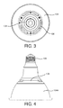
Fig. 3 shows a bottom view of the lighting device illustrated inFig. 1 ; -
Fig. 4 shows a side view of the lighting device illustrated inFig. 1 ; -
Fig. 5 shows a schematic sectional side view of the lighting device illustrated inFig. 1 ; -
Fig. 6 illustrates the air velocity around and within the lighting device illustrated inFig. 1 during operation; -
Fig. 7 shows a lighting device according to another embodiment of the invention; -
Fig. 8 shows a schematic sectional side view of the lighting device illustrated inFig. 7 . - An embodiment of the lighting device according to the present inventive concept is illustrated in
Fig. 1 , and different views of the lighting device are presented inFigs. 2 to 5 .Fig. 1 shows aPAR lamp 100 with LEDs or a LED array representing alight source 101 mounted in the front end opposite to thebase 109. Thelight source 101 is thermally coupled to acover 103 and aheat sink component 104. There areholes 102 in thecover 103, and holes 106 in theheat sink component 104. Thecover 103 may act as an additional heat sink component and is thermally coupled to theheat sink component 104 at least along its outer periphery. - As shown in
Fig 5 , thecover 103 has arecess 1031 for accommodating thelight source 101. Alternatively, thelight source 101 is provided on theheat sink component 104, for example on the bottom part of therecess 1031, and thecover 103 comprises a light exit window where the light from thelight source 101 can exit. Theheat sink component 104 is, in this case, cup-shaped, and has aside wall 1044 and a bottom 1043 with aprotrusion 1041 provided in thebottom 1043 of theheat sink component 104. Theprotrusion 1041 is adapted for receiving and partly enclosing anelectronic driving component 108 which is adapted to provide energy to thelight source 101. Furthermore, ahousing 107 is provided between theheat sink component 104 and thebase 109. Thehousing 107 can be made of plastic and provides a safety shield for theelectronic driving component 108. - The
cover 103 and theheat sink component 104 are, in this case, assembled with a good thermal connection at therecess bottom 1032 and theprotrusion top surface 1042, in addition to the thermal contact between the side wall of theheat sink component 104 and the outer periphery of thecover 103. The heat generated by thelight source 101 will, in this case, be conducted to theheat sink component 104 and thecover 103, in this case also acting as a heat sink, and will be dissipated relatively well at the exposed surfaces of theheat sink component 104 and thecover 103. The thermal connection between the recessedbottom 1032 and theprotrusion top surface 1042 can be established via direct attachment or via a thermally conducting medium, such as thermal glue or thermal filler. The thermal connection thickens the base of the heat sink and results in a better temperature distribution under the heat source. - An
air chamber 1051 is formed between thecover 103 and theheat sink component 104. As shown inFig. 2 ,first holes 102 are provided in arim 1033 around therecess 1031 of thecover 103, thereby creating a first connection between theair chamber 1051 and ambient air. Furthermore,second holes 106 are provided in thebottom 1043 of theheat sink component 104 adjacent to theside wall 1044, thereby creating a second connection between theair chamber 1051 and ambient air. First andsecond holes air chamber 1051, form a channel allowing air to flow through theair chamber 1051, as the dash-linedarrow 105 indicates. When thelamp 100 is operated as is illustrated inFig. 5 , in this case a down-lighting, a chimney effect will be created in the heat sink structure, as is illustrated inFig. 6 which shows the air flow inside and outside thelamp 100, wherein the arrows indicate the direction (direction of arrow) and the speed (size of arrow) of the airflow. The heat source, i.e. thelight source 101, pre-heats the airflow and creates a buoyancy force. The higher the temperature of the air becomes, the larger the driving force will be. This driving force is created by the density difference between hot air and the relatively cold ambient air. In a gravitational field, the hot air becomes less dense and rises, driven by the buoyancy force. Meanwhile, the cold air follows, taking up the space left by hot air, thus creating the airflow. When the air passes through the channel, it has been and will be heated and thus stores a certain amount of energy. As long as the air leaves the channel or air chamber, the heat is transported away. The heat produced by LEDs is mainly removed through the moving air, including both internal (in the chimney channel or air chamber) and external moving air, i.e. outside the lighting device. - At the same time, radiation heat transfer is also a significant source for dissipating the generated heat in addition to natural convection. Both the
rim 1033 of thecover 103 and theside wall 1044 of the cup-shapedheat sink component 104 are exposed to ambient air, and allow radiation heat transfer. - The
air flow direction 105 is upwards inFig.5 . However, a person skilled in the art can understand that theair flow direction 105 can be reversed in situations where thelamp 100 operates in another direction. The chimney effect can be built up within theair chamber 1051 of the heat sink component because of a temperature gradient, and will force the air to flow through theair chamber 1051. - In this embodiment, the cross section of the channel between the inlet, i.e. first or second holes 105,106, and outlet, i.e. second or
first holes air chamber 1051 is as low as possible and the overall flow losses in the system are minimized. This is advantageous because it decreases the thermal resistance. - As is shown in
Fig. 4 , which is an outside view of thelamp 100, theside wall 1044 of theheat sink component 104 is an intact smooth exposed surface, without holes, slots or fins, which provides an ornamental effect. -
Fig. 7 and Fig. 8 show another embodiment of the invention, wherein aBR lamp 200 has anarrow slit 202 inside wall 2044 ofheat sink component 204 adjacent or near to arim 2033 of acover 203 instead of thefirst holes 102 in thecover 103 in the first embodiment. Thenarrow slit 202 is hardly visible, while, also in this embodiment, the internal structure (air chamber 2051) is much wider.Second holes 206 are provided in thebottom 2043 of the cup-shapedheat sink component 204. Also in this embodiment, theside wall 2044 is an intact smooth exposed surface, without holes, slots or fins, which provides an ornamental effect. In addition, areflector 211 is included in therecess 2031 of thecover 203 providing a desired optical performance of thelamp 200. - The protrusion of the
heat sink component 204 is relatively small in height compared to the height of the protrusion of theheat sink component 104 of the first embodiment. And, therefore, in this case the electronic driving component is accommodated in the housing. The airflow withinair chamber 2051 formed between thecover 203 and theheat sink component 204 provides an optimal thermal performance. - A person skilled in the art can understand that other types of back-reflecting lamp bulbs, such as GU, MR, etc., can adopt the same principle to achieve a lamp with a smooth appearance and the advantages of low cost, good manufacturability and high heat dissipation capability.
- A person skilled in the art realizes that the present invention by no means is limited to the preferred embodiments described above. On the contrary, many modifications and variations are possible within the scope of the appended claims. It should be noted that the above-mentioned embodiments illustrate rather than limit the invention and that those skilled in the art will be able to design alternative embodiments without departing from the scope of the appended claims. In the claims, any reference signs placed between parentheses shall not be constructed as limiting the claim. The word "comprising" does not exclude the presence of elements or steps not listed in a claim. The word "a" or "an" preceding an element does not exclude the presence of a plurality of such elements. The usage of the words first, second and third, etc., does not indicate any ordering. These words are to be interpreted as names. No specific sequence of acts is intended to be required unless specifically indicated.
Claims (15)
- A lighting device (100, 200) comprising:at least one light source (101);a heat sink component (104, 204) having a bottom (1043) and a side wall (1044) extending from the bottom (1043), wherein the bottom (1043) comprises a protrusion (1041) and wherein the at least one light source (101) thermally contacts the protrusion (1041) of the heat sink component (104, 204); anda cover (103, 203) provided on the sidewall (1044) and opposite to the bottom (1044), thereby defining an air chamber (1051, 2051) between the cover, the side wall (1044), the bottom (1044) and the protrusion (1041).
- The lighting device according to claim 1, wherein the cover (103, 203) is of a thermally conductive material which thermally contacts the side wall (1044) of the heat sink component (104, 204).
- The lighting device according to claim 2, wherein the cover (103, 203) comprises a recess (1031, 2031) which accommodates the at least one light source (101).
- The lighting device according to claim 3, wherein the recess (1031, 2031) thermally contacts the protrusion (1041).
- The lighting device according to any one of the preceding claims, wherein the protrusion (1041) has a side surface and a top surface, and wherein the side surface, not the top surface, of the protrusion (1041) forms a portion of the air chamber (1051, 2051).
- The lighting device according to any one of the preceding claims, wherein the cover (103, 203) comprises a first opening (102, 202), the heat sink component (104, 204) comprises a second opening (106, 206), and the air chamber (1051, 2051) forms a channel between the first opening (102, 202) and the second opening (106, 206) to allow a flow of air between the first and the second opening or vice versa.
- The lighting device according to claim 6, wherein a cross section of the channel is larger than at least one of the first opening (102, 202) and the second opening (106,206).
- The lighting device according to claim 6 or 7, wherein the cover (103) comprises a rim (1033) at its outer periphery, and the first opening (102) comprises a plurality of holes near the rim (1033).
- The lighting device according to any one of claims 1 or 5, wherein the heat sink component (204) comprises a first and a second opening (202, 206), and the air chamber (1051, 2051) forms a channel between the first opening (202) and the second opening (206) to allow a flow of air between the first and second opening or vice versa, and wherein the first opening (202) is a slit in the side wall (2044) of the heat sink component (204).
- The lighting device according to any one of claims 6 to 9, wherein the second opening (106, 206) comprises a plurality of holes in the bottom (1043, 2043) of the heat sink component (104, 204) between the protrusion and the side wall (1044, 2044) of the heat sink component (104, 204).
- The lighting device according to claim 10, wherein the side wall (1044, 2044) has an intact smooth exposed surface.
- The lighting device according to any one of claims 6 to 8, wherein the second opening (106, 206) comprises a plurality of holes in the side wall (1044, 2044) of the heat sink component (104, 204) adjacent to the bottom (1043, 2043) of the heat sink component (104,204).
- The lighting device according to claim 3 or 4, wherein the recess (2031) further comprises a reflector (211).
- The lighting device according to any one of the preceding claims, wherein the protrusion (1041) encompasses at least a part of an electronic component (108, 208).
- A luminaire comprising a lighting device according to any one of claims 1 to 14.
Priority Applications (8)
| Application Number | Priority Date | Filing Date | Title |
|---|---|---|---|
| EP12168673.7A EP2667083A1 (en) | 2012-05-21 | 2012-05-21 | Lighting device with smooth outer appearance |
| PL13726598T PL2839204T3 (en) | 2012-04-20 | 2013-04-16 | Lighting device with smooth outer appearance |
| CN201380020009.2A CN104334957A (en) | 2012-04-20 | 2013-04-16 | Lighting device with smooth outer appearance |
| PCT/IB2013/052999 WO2013156919A1 (en) | 2012-04-20 | 2013-04-16 | Lighting device with smooth outer appearance |
| US14/395,532 US9476580B2 (en) | 2012-04-20 | 2013-04-16 | Lighting device with smooth outer appearance |
| EP13726598.9A EP2839204B1 (en) | 2012-04-20 | 2013-04-16 | Lighting device with smooth outer appearance |
| US15/299,782 US10215393B2 (en) | 2012-04-20 | 2016-10-21 | Lighting device with smooth outer appearance |
| US16/260,696 US10663158B2 (en) | 2012-04-20 | 2019-01-29 | Lighting device with smooth outer appearance |
Applications Claiming Priority (1)
| Application Number | Priority Date | Filing Date | Title |
|---|---|---|---|
| EP12168673.7A EP2667083A1 (en) | 2012-05-21 | 2012-05-21 | Lighting device with smooth outer appearance |
Publications (1)
| Publication Number | Publication Date |
|---|---|
| EP2667083A1 true EP2667083A1 (en) | 2013-11-27 |
Family
ID=46125286
Family Applications (1)
| Application Number | Title | Priority Date | Filing Date |
|---|---|---|---|
| EP12168673.7A Withdrawn EP2667083A1 (en) | 2012-04-20 | 2012-05-21 | Lighting device with smooth outer appearance |
Country Status (2)
| Country | Link |
|---|---|
| EP (1) | EP2667083A1 (en) |
| CN (1) | CN104334957A (en) |
Families Citing this family (2)
| Publication number | Priority date | Publication date | Assignee | Title |
|---|---|---|---|---|
| CN105674108A (en) * | 2016-03-24 | 2016-06-15 | 海宁博华照明电器有限公司 | Novel LED lamp |
| CN110736086B (en) * | 2019-11-29 | 2024-08-09 | 福建省中科生物股份有限公司 | Radiator device |
Citations (1)
| Publication number | Priority date | Publication date | Assignee | Title |
|---|---|---|---|---|
| US20120044680A1 (en) * | 2010-08-19 | 2012-02-23 | Lm Opto Co., Ltd. | Illuminating device with light emitting diodes |
Family Cites Families (5)
| Publication number | Priority date | Publication date | Assignee | Title |
|---|---|---|---|---|
| US7575346B1 (en) * | 2008-07-22 | 2009-08-18 | Sunonwealth Electric Machine Industry Co., Ltd. | Lamp |
| US8907550B2 (en) * | 2009-03-16 | 2014-12-09 | Molex Incorporated | Light module |
| US8164237B2 (en) * | 2010-07-29 | 2012-04-24 | GEM-SUN Technologies Co., Ltd. | LED lamp with flow guide function |
| CN201866640U (en) * | 2010-10-29 | 2011-06-15 | 伍永乐 | LED (light emitting diode) spotlight |
| CN201787542U (en) * | 2010-11-24 | 2011-04-06 | 宁波同泰电气股份有限公司 | LED lamp inside-outside circulating convection type heat dissipating structure |
-
2012
- 2012-05-21 EP EP12168673.7A patent/EP2667083A1/en not_active Withdrawn
-
2013
- 2013-04-16 CN CN201380020009.2A patent/CN104334957A/en active Pending
Patent Citations (1)
| Publication number | Priority date | Publication date | Assignee | Title |
|---|---|---|---|---|
| US20120044680A1 (en) * | 2010-08-19 | 2012-02-23 | Lm Opto Co., Ltd. | Illuminating device with light emitting diodes |
Also Published As
| Publication number | Publication date |
|---|---|
| CN104334957A (en) | 2015-02-04 |
Similar Documents
| Publication | Publication Date | Title |
|---|---|---|
| US10663158B2 (en) | Lighting device with smooth outer appearance | |
| JP6199970B2 (en) | Heat dissipation structure with segmented chimney structure | |
| RU2662691C2 (en) | Lighting device and luminaire | |
| US20080285265A1 (en) | Luminaire System with Thermal Chimney Effect | |
| CN110720013B (en) | Solid-state lighting lamp | |
| CN105531528B (en) | lighting device | |
| JP2013232411A (en) | Lamp cover and lighting device having the same | |
| EP3578873A1 (en) | Lighting fixture for vehicle | |
| EP2667083A1 (en) | Lighting device with smooth outer appearance | |
| CN203052408U (en) | Fast cooling LED track light | |
| WO2013107731A1 (en) | Illuminating device and luminaire having the illuminating device | |
| CN101663531B (en) | Cooling reflectors for luminaires | |
| CN112997037A (en) | Lamp with circumferentially closed heat dissipation body | |
| CN105308389A (en) | Lighting device and luminaire | |
| JP2013247078A (en) | Lighting device | |
| WO2017018902A1 (en) | Led bulb | |
| RU167546U1 (en) | LED LAMP | |
| CN105264291B (en) | Air cooling of electronic drives in lighting fixtures | |
| CN203810102U (en) | Lighting lamp | |
| CN104603534B (en) | Radiator structure with division chimney structure | |
| TW201144681A (en) | Light-emitting diode lamp |
Legal Events
| Date | Code | Title | Description |
|---|---|---|---|
| PUAI | Public reference made under article 153(3) epc to a published international application that has entered the european phase |
Free format text: ORIGINAL CODE: 0009012 |
|
| AK | Designated contracting states |
Kind code of ref document: A1 Designated state(s): AL AT BE BG CH CY CZ DE DK EE ES FI FR GB GR HR HU IE IS IT LI LT LU LV MC MK MT NL NO PL PT RO RS SE SI SK SM TR |
|
| AX | Request for extension of the european patent |
Extension state: BA ME |
|
| STAA | Information on the status of an ep patent application or granted ep patent |
Free format text: STATUS: THE APPLICATION IS DEEMED TO BE WITHDRAWN |
|
| 18D | Application deemed to be withdrawn |
Effective date: 20140528 |