EP2666970A1 - Gas turbine system having a plasma actuator flow control arrangement - Google Patents
Gas turbine system having a plasma actuator flow control arrangement Download PDFInfo
- Publication number
- EP2666970A1 EP2666970A1 EP13168391.4A EP13168391A EP2666970A1 EP 2666970 A1 EP2666970 A1 EP 2666970A1 EP 13168391 A EP13168391 A EP 13168391A EP 2666970 A1 EP2666970 A1 EP 2666970A1
- Authority
- EP
- European Patent Office
- Prior art keywords
- inlet
- airstream
- plasma actuator
- gas turbine
- electrode
- Prior art date
- Legal status (The legal status is an assumption and is not a legal conclusion. Google has not performed a legal analysis and makes no representation as to the accuracy of the status listed.)
- Withdrawn
Links
- 230000005684 electric field Effects 0.000 claims abstract description 12
- 238000011144 upstream manufacturing Methods 0.000 claims description 4
- 239000007789 gas Substances 0.000 description 39
- 238000000926 separation method Methods 0.000 description 8
- 239000000446 fuel Substances 0.000 description 7
- 230000008901 benefit Effects 0.000 description 4
- 230000008859 change Effects 0.000 description 3
- 230000003750 conditioning effect Effects 0.000 description 2
- 239000003989 dielectric material Substances 0.000 description 2
- VNWKTOKETHGBQD-UHFFFAOYSA-N methane Chemical compound C VNWKTOKETHGBQD-UHFFFAOYSA-N 0.000 description 2
- 239000000203 mixture Substances 0.000 description 2
- UFHFLCQGNIYNRP-UHFFFAOYSA-N Hydrogen Chemical compound [H][H] UFHFLCQGNIYNRP-UHFFFAOYSA-N 0.000 description 1
- 230000004075 alteration Effects 0.000 description 1
- 230000000712 assembly Effects 0.000 description 1
- 238000000429 assembly Methods 0.000 description 1
- 230000015572 biosynthetic process Effects 0.000 description 1
- 238000002485 combustion reaction Methods 0.000 description 1
- 238000001816 cooling Methods 0.000 description 1
- 238000001914 filtration Methods 0.000 description 1
- 239000012530 fluid Substances 0.000 description 1
- 239000001257 hydrogen Substances 0.000 description 1
- 229910052739 hydrogen Inorganic materials 0.000 description 1
- 239000007788 liquid Substances 0.000 description 1
- 239000003345 natural gas Substances 0.000 description 1
- 230000009467 reduction Effects 0.000 description 1
- 238000006467 substitution reaction Methods 0.000 description 1
- 230000007704 transition Effects 0.000 description 1
Images

Classifications
-
- F—MECHANICAL ENGINEERING; LIGHTING; HEATING; WEAPONS; BLASTING
- F01—MACHINES OR ENGINES IN GENERAL; ENGINE PLANTS IN GENERAL; STEAM ENGINES
- F01D—NON-POSITIVE DISPLACEMENT MACHINES OR ENGINES, e.g. STEAM TURBINES
- F01D9/00—Stators
- F01D9/02—Nozzles; Nozzle boxes; Stator blades; Guide conduits, e.g. individual nozzles
- F01D9/04—Nozzles; Nozzle boxes; Stator blades; Guide conduits, e.g. individual nozzles forming ring or sector
- F01D9/041—Nozzles; Nozzle boxes; Stator blades; Guide conduits, e.g. individual nozzles forming ring or sector using blades
-
- F—MECHANICAL ENGINEERING; LIGHTING; HEATING; WEAPONS; BLASTING
- F02—COMBUSTION ENGINES; HOT-GAS OR COMBUSTION-PRODUCT ENGINE PLANTS
- F02C—GAS-TURBINE PLANTS; AIR INTAKES FOR JET-PROPULSION PLANTS; CONTROLLING FUEL SUPPLY IN AIR-BREATHING JET-PROPULSION PLANTS
- F02C7/00—Features, components parts, details or accessories, not provided for in, or of interest apart form groups F02C1/00 - F02C6/00; Air intakes for jet-propulsion plants
- F02C7/04—Air intakes for gas-turbine plants or jet-propulsion plants
-
- F—MECHANICAL ENGINEERING; LIGHTING; HEATING; WEAPONS; BLASTING
- F05—INDEXING SCHEMES RELATING TO ENGINES OR PUMPS IN VARIOUS SUBCLASSES OF CLASSES F01-F04
- F05D—INDEXING SCHEME FOR ASPECTS RELATING TO NON-POSITIVE-DISPLACEMENT MACHINES OR ENGINES, GAS-TURBINES OR JET-PROPULSION PLANTS
- F05D2270/00—Control
- F05D2270/01—Purpose of the control system
- F05D2270/17—Purpose of the control system to control boundary layer
- F05D2270/172—Purpose of the control system to control boundary layer by a plasma generator, e.g. control of ignition
Definitions
- the subject matter disclosed herein relates generally to gas turbine systems, and more particularly to plasma actuators disposed within such systems.
- Inlet assemblies for gas turbine systems typically include an intake portion that provides an intake path for an airstream to enter the inlet assembly and the intake portions often include conditioning features such as weather hoods or louvers. Downstream of the louvers or hoods, various filtration and airstream conditioning components may be included to treat the airstream.
- An inlet duct is configured to contain and route the treated airstream to a gas turbine inlet plenum, and subsequently to an inlet portion of a compressor. Routing of the airstream through the inlet assembly typically includes changes in geometry and/or rapid redirection of the airstream, thereby causing flow separation at various regions and results in an undesirable pressure drop of the airstream.
- a gas turbine system has a plasma actuator flow control arrangement including a compressor section for compressing an airstream, wherein the compressor section includes at least one inlet guide vane for controlling the airstream proximate an inlet portion of the compressor section. Also included is a turbine inlet assembly for ingesting the airstream to be routed to the compressor section. Further included is a plasma actuator disposed within at least one of the inlet portion of the compressor section and the turbine inlet assembly for controllably producing an electric field to manipulate a portion of the airstream.
- a gas turbine system has a plasma actuator flow control arrangement including a turbine inlet assembly for ingesting an airstream to be routed to a compressor section, wherein the turbine inlet assembly includes an outer wall enclosing an airstream path. Also included is a plasma actuator disposed proximate the outer wall of the turbine inlet assembly for controllably producing an electric field to manipulate a portion of the airstream.
- a gas turbine system has a plasma actuator flow control arrangement including a compressor section for compressing an airstream, wherein the compressor section includes an inlet portion. Also included is a plasma actuator disposed proximate the inlet portion of the compressor section, wherein the plasma actuator controllably produces an electric field to manipulate a portion of the airstream.
- a gas turbine system is schematically illustrated with reference numeral 10.
- the gas turbine system 10 includes a compressor 12, a combustor 14, a turbine 16, a shaft 18 and a fuel nozzle 20.
- the compressor 12 and the turbine 16 are coupled by the shaft 18.
- the shaft 18 may be a single shaft or a plurality of shaft segments coupled together to form the shaft 18.
- a turbine inlet assembly 22 ingests an airstream 24 that is filtered and routed to the compressor 12.
- the combustor 14 uses a combustible liquid and/or gas fuel, such as natural gas or a hydrogen rich synthetic gas, to run the gas turbine system 10.
- fuel nozzles 20 are in fluid communication with an air supply and a fuel supply 26.
- the fuel nozzles 20 create an air-fuel mixture, and discharge the air-fuel mixture into the combustor 14, thereby causing a combustion that creates a hot pressurized exhaust gas.
- the combustor 14 directs the hot pressurized gas through a transition piece into a turbine nozzle (or "stage one nozzle"), and other stages of buckets and nozzles causing rotation of the turbine 16. Rotation of the turbine 16 causes the shaft 18 to rotate, thereby compressing the air as it flows into the compressor 12.
- the turbine inlet assembly 22 includes an entry portion 30 for the airstream 24, where the entry portion 30 typically comprises one or more weather hoods or louvers.
- the entry portion 30 provides a path for the airstream 24 to enter an inlet filter compartment 32 from ambient surroundings.
- various anti-icing devices may be disposed proximate and/or downstream of the entry portion 30 to prevent ice formation and plugging within the turbine inlet assembly 22.
- optional cooling components may be employed to reduce the dry bulb temperature of the airstream 24.
- An inlet duct 34 is configured to contain and route the airstream to an inlet plenum 36.
- the inlet duct 34 comprises numerous sections that may vary in orientation and geometric configuration.
- a first duct portion 38 is shown as having a relatively horizontal orientation prior to redirection through an elbow 40 to a second duct portion 42 having a relatively vertical orientation.
- the inlet plenum 36 is configured to provide a relatively turbulent-free region for immediate entry of the airstream 24 to the compressor 12.
- the airstream 24 is subjected to yet another redirection during entry to the compressor 12 through the inlet plenum 36.
- the inlet plenum 36 directs the airstream 24 into a compressor inlet bellmouth 46.
- a plasma actuator 44 is disposed within the turbine inlet assembly 22.
- the plasma actuator 44 may be disposed at any region of the turbine inlet assembly 22 that subjects the airstream 24 to a rapid change in orientation and/or geometric configuration.
- Regions proximate the elbow 40, the inlet plenum 36 and the compressor inlet bellmouth 46 are examples of locations where disposal of the plasma actuator 44 may assist in reduction of flow separation exhibited at such regions. Although the previously mentioned regions are exemplary locations known to benefit from use of the plasma actuator 44, it is to be understood that the plasma actuator 44 may be located anywhere within the turbine inlet assembly 22.
- the plasma actuator 44 controllably produces an electric field to manipulate a portion of the airstream 24 proximate an area typically associated with flow separation, including but not limited to an outer wall 48 ( FIG. 2 ) of the turbine inlet assembly 22, the outer wall 48 defining and enclosing the path of the airstream 24, or on a wall 50 of the inlet plenum 36, for example.
- the plasma actuator 44 includes a first electrode 52, a second electrode 54 and a dielectric material 56 having a first side 58 and a second side 60, to which the first electrode 52 and the second electrode 54 are arranged in proximity to, respectively.
- the dielectric material 56 may be configured for conforming to a variety of geometric surfaces, including non-planar surfaces, as well as relatively planar surfaces.
- the first electrode 52 and the second electrode 54 are operably connected to an energy source 62. Both the first electrode 52 and the second electrode 54 comprise relatively low-diameter wires flush-mounted on the wall 50, for example, but as noted above the first electrode 52 and the second electrode 54 may be positioned at numerous locations within the turbine inlet assembly 22.
- the energy source 62 provides alternating current (AC) or direct current (DC) power to the first electrode 52 and the second electrode 54.
- AC alternating current
- DC direct current
- the airstream 24 ionizes in a region of the largest electric potential to form plasma.
- the plasma forms around one of the first electrode 52 and the second electrode 54 and spreads over an area tangential to the wall 50, in the form of an electric field.
- the plasma produces a force on the airstream 24, which in turn causes a change in the pressure distribution along whatever surface the plasma actuator 44 is disposed in proximity to.
- the change in pressure distribution generally reduces or substantially prevents flow separation when the plasma actuator 44 is energized by the energy source 62.
- the inlet portion 70 includes at least one strut 72 that provides structural support proximate an inlet casing 74 of the compressor 12. Additionally, the inlet portion 70 includes at least one, but typically a plurality of, inlet guide vanes 76 that may have variable aerodynamic vane positions. The angle of the at least one inlet guide vanes 76 may vary based on different ranges of compressor flows (i.e., startup and various unit power output settings), thereby improving operating efficiency of the compressor 12. For example, during extended turn down operation of the gas turbine system 10, the angle of the inlet guide vanes 76 may be reduced.
- the plasma actuator 44 may be disposed proximate one or both component.
- the plasma actuator 44 has been described in detail above and further description is not necessary. As shown, the plasma actuator 44, or a plurality of plasma actuators, may be disposed at various locations on the strut 72 and/or the inlet guide vanes 76.
- the flow profile of the airstream 24 in regions of the turbine inlet assembly 22 and the inlet portion 70 of the compressor 12 may be better controlled, while reducing fluctuations in the airstream 24 that occur due to upstream disturbances.
- the overall efficiency of the gas turbine system 10 is improved by use of the plasma actuator 44, which requires a relatively low amount of power consumption with real-time control.
Landscapes
- Engineering & Computer Science (AREA)
- Chemical & Material Sciences (AREA)
- Combustion & Propulsion (AREA)
- Mechanical Engineering (AREA)
- General Engineering & Computer Science (AREA)
- Structures Of Non-Positive Displacement Pumps (AREA)
- Physical Or Chemical Processes And Apparatus (AREA)
Abstract
Description
- The subject matter disclosed herein relates generally to gas turbine systems, and more particularly to plasma actuators disposed within such systems.
- Inlet assemblies for gas turbine systems typically include an intake portion that provides an intake path for an airstream to enter the inlet assembly and the intake portions often include conditioning features such as weather hoods or louvers. Downstream of the louvers or hoods, various filtration and airstream conditioning components may be included to treat the airstream. An inlet duct is configured to contain and route the treated airstream to a gas turbine inlet plenum, and subsequently to an inlet portion of a compressor. Routing of the airstream through the inlet assembly typically includes changes in geometry and/or rapid redirection of the airstream, thereby causing flow separation at various regions and results in an undesirable pressure drop of the airstream.
- According to one aspect of the invention, a gas turbine system has a plasma actuator flow control arrangement including a compressor section for compressing an airstream, wherein the compressor section includes at least one inlet guide vane for controlling the airstream proximate an inlet portion of the compressor section. Also included is a turbine inlet assembly for ingesting the airstream to be routed to the compressor section. Further included is a plasma actuator disposed within at least one of the inlet portion of the compressor section and the turbine inlet assembly for controllably producing an electric field to manipulate a portion of the airstream.
- According to another aspect of the invention, a gas turbine system has a plasma actuator flow control arrangement including a turbine inlet assembly for ingesting an airstream to be routed to a compressor section, wherein the turbine inlet assembly includes an outer wall enclosing an airstream path. Also included is a plasma actuator disposed proximate the outer wall of the turbine inlet assembly for controllably producing an electric field to manipulate a portion of the airstream.
- According to yet another aspect of the invention, a gas turbine system has a plasma actuator flow control arrangement including a compressor section for compressing an airstream, wherein the compressor section includes an inlet portion. Also included is a plasma actuator disposed proximate the inlet portion of the compressor section, wherein the plasma actuator controllably produces an electric field to manipulate a portion of the airstream.
- Various advantages and features will become more apparent from the following description taken in conjunction with the drawings.
- The subject matter, which is regarded as the invention, is particularly pointed out and distinctly claimed in the claims at the conclusion of the specification. The foregoing and other features and advantages of the invention are apparent from the following detailed description taken in conjunction with the accompanying drawings in which:
-
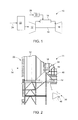
FIG. 1 is a schematic illustration of a gas turbine system; -
FIG. 2 is a side, elevational view of an inlet assembly of the gas turbine system; -
FIG. 3 is a schematic illustration of a plasma actuator disposed within a portion of the gas turbine system; and -
FIG. 4 is a side, cross-sectional view of an inlet portion of a compressor section of the gas turbine system. - The detailed description explains embodiments of the invention, together with advantages and features, by way of example with reference to the drawings.
- Referring to
FIG. 1 , a gas turbine system is schematically illustrated withreference numeral 10. Thegas turbine system 10 includes acompressor 12, acombustor 14, aturbine 16, ashaft 18 and afuel nozzle 20. Thecompressor 12 and theturbine 16 are coupled by theshaft 18. Theshaft 18 may be a single shaft or a plurality of shaft segments coupled together to form theshaft 18. Additionally, aturbine inlet assembly 22 ingests anairstream 24 that is filtered and routed to thecompressor 12. - The
combustor 14 uses a combustible liquid and/or gas fuel, such as natural gas or a hydrogen rich synthetic gas, to run thegas turbine system 10. For example,fuel nozzles 20 are in fluid communication with an air supply and afuel supply 26. Thefuel nozzles 20 create an air-fuel mixture, and discharge the air-fuel mixture into thecombustor 14, thereby causing a combustion that creates a hot pressurized exhaust gas. Thecombustor 14 directs the hot pressurized gas through a transition piece into a turbine nozzle (or "stage one nozzle"), and other stages of buckets and nozzles causing rotation of theturbine 16. Rotation of theturbine 16 causes theshaft 18 to rotate, thereby compressing the air as it flows into thecompressor 12. - Referring to
FIG. 2 , theturbine inlet assembly 22 is illustrated in greater detail. Theturbine inlet assembly 22 includes anentry portion 30 for theairstream 24, where theentry portion 30 typically comprises one or more weather hoods or louvers. Theentry portion 30 provides a path for theairstream 24 to enter aninlet filter compartment 32 from ambient surroundings. In cooler operating environments, various anti-icing devices may be disposed proximate and/or downstream of theentry portion 30 to prevent ice formation and plugging within theturbine inlet assembly 22. Additionally, optional cooling components may be employed to reduce the dry bulb temperature of theairstream 24. Aninlet duct 34 is configured to contain and route the airstream to aninlet plenum 36. Theinlet duct 34 comprises numerous sections that may vary in orientation and geometric configuration. For example, afirst duct portion 38 is shown as having a relatively horizontal orientation prior to redirection through anelbow 40 to asecond duct portion 42 having a relatively vertical orientation. Theinlet plenum 36 is configured to provide a relatively turbulent-free region for immediate entry of theairstream 24 to thecompressor 12. Theairstream 24 is subjected to yet another redirection during entry to thecompressor 12 through theinlet plenum 36. Theinlet plenum 36 directs theairstream 24 into acompressor inlet bellmouth 46. - Referring to
FIG. 3 , in regions of redirection and/or variance in geometric configuration of theairstream 24 path, flow separation may occur, with a boundary layer forming proximate structural components of theturbine inlet assembly 22. To reduce flow separation and associated pressure drop within theturbine inlet assembly 22, aplasma actuator 44 is disposed within theturbine inlet assembly 22. Although a single plasma actuator is described, it is to be appreciated that a plurality of such plasma actuators may be employed and is dictated by the application of use. Theplasma actuator 44 may be disposed at any region of theturbine inlet assembly 22 that subjects theairstream 24 to a rapid change in orientation and/or geometric configuration. Regions proximate theelbow 40, theinlet plenum 36 and thecompressor inlet bellmouth 46 are examples of locations where disposal of theplasma actuator 44 may assist in reduction of flow separation exhibited at such regions. Although the previously mentioned regions are exemplary locations known to benefit from use of theplasma actuator 44, it is to be understood that theplasma actuator 44 may be located anywhere within theturbine inlet assembly 22. - The
plasma actuator 44 controllably produces an electric field to manipulate a portion of theairstream 24 proximate an area typically associated with flow separation, including but not limited to an outer wall 48 (FIG. 2 ) of theturbine inlet assembly 22, theouter wall 48 defining and enclosing the path of theairstream 24, or on awall 50 of theinlet plenum 36, for example. Theplasma actuator 44 includes afirst electrode 52, asecond electrode 54 and adielectric material 56 having afirst side 58 and asecond side 60, to which thefirst electrode 52 and thesecond electrode 54 are arranged in proximity to, respectively. Thedielectric material 56 may be configured for conforming to a variety of geometric surfaces, including non-planar surfaces, as well as relatively planar surfaces. Thefirst electrode 52 and thesecond electrode 54 are operably connected to anenergy source 62. Both thefirst electrode 52 and thesecond electrode 54 comprise relatively low-diameter wires flush-mounted on thewall 50, for example, but as noted above thefirst electrode 52 and thesecond electrode 54 may be positioned at numerous locations within theturbine inlet assembly 22. Theenergy source 62 provides alternating current (AC) or direct current (DC) power to thefirst electrode 52 and thesecond electrode 54. Upon reaching a threshold value voltage, theairstream 24 ionizes in a region of the largest electric potential to form plasma. The plasma forms around one of thefirst electrode 52 and thesecond electrode 54 and spreads over an area tangential to thewall 50, in the form of an electric field. The plasma produces a force on theairstream 24, which in turn causes a change in the pressure distribution along whatever surface theplasma actuator 44 is disposed in proximity to. The change in pressure distribution generally reduces or substantially prevents flow separation when theplasma actuator 44 is energized by theenergy source 62. - Referring now to
FIG. 4 , aninlet portion 70 of thecompressor 12 is illustrated. Theinlet portion 70 includes at least onestrut 72 that provides structural support proximate aninlet casing 74 of thecompressor 12. Additionally, theinlet portion 70 includes at least one, but typically a plurality of,inlet guide vanes 76 that may have variable aerodynamic vane positions. The angle of the at least oneinlet guide vanes 76 may vary based on different ranges of compressor flows (i.e., startup and various unit power output settings), thereby improving operating efficiency of thecompressor 12. For example, during extended turn down operation of thegas turbine system 10, the angle of theinlet guide vanes 76 may be reduced. An increased chance of flow separation of a portion of theairstream 24 is present during such a configuration of theinlet guide vanes 76, thereby creating flow disturbances in theinlet portion 70 of thecompressor 12. To reduce flow separation in regions proximate thestrut 72 and/or theinlet guide vanes 76, or more specifically anexterior surface 78 of theinlet guide vanes 76, theplasma actuator 44 may be disposed proximate one or both component. Theplasma actuator 44 has been described in detail above and further description is not necessary. As shown, theplasma actuator 44, or a plurality of plasma actuators, may be disposed at various locations on thestrut 72 and/or the inlet guide vanes 76. - Accordingly, the flow profile of the airstream 24 in regions of the
turbine inlet assembly 22 and theinlet portion 70 of thecompressor 12 may be better controlled, while reducing fluctuations in the airstream 24 that occur due to upstream disturbances. The overall efficiency of thegas turbine system 10 is improved by use of theplasma actuator 44, which requires a relatively low amount of power consumption with real-time control. - While the invention has been described in detail in connection with only a limited number of embodiments, it should be readily understood that the invention is not limited to such disclosed embodiments. Rather, the invention can be modified to incorporate any number of variations, alterations, substitutions or equivalent arrangements not heretofore described, but which are commensurate with the spirit and scope of the invention. Additionally, while various embodiments of the invention have been described, it is to be understood that aspects of the invention may include only some of the described embodiments. Accordingly, the invention is not to be seen as limited by the foregoing description, but is only limited by the scope of the appended claims.
- Various aspects and embodiments of the present invention are defined by the following numbered clauses:
- 1. A gas turbine system having a plasma actuator flow control arrangement comprising:
- a compressor section for compressing an airstream, wherein the compressor section includes at least one inlet guide vane for controlling the airstream proximate an inlet portion of the compressor section;
- a turbine inlet assembly for ingesting the airstream to be routed to the compressor section; and
- a plasma actuator disposed within at least one of the inlet portion of the compressor section and the turbine inlet assembly for controllably producing an electric field to manipulate a portion of the airstream.
- 2. The gas turbine system of clause 1, wherein the turbine inlet assembly includes a first duct portion for routing the airstream in a first direction, a second duct portion for routing the airstream in a second direction, and an elbow for transitioning the airstream from the first duct portion to the second duct portion, wherein the plasma actuator is disposed within the elbow.
- 3. The gas turbine system of any preceding clause, wherein the turbine inlet assembly includes an inlet plenum disposed upstream of, and proximate to, the inlet portion of the compressor section, wherein the plasma actuator is disposed within the inlet plenum.
- 4. The gas turbine system of any preceding clause, wherein the inlet plenum comprises a compressor inlet bellmouth, wherein the plasma actuator is disposed proximate the compressor inlet bellmouth.
- 5. The gas turbine system of any preceding clause, wherein the at least one inlet guide vane comprises an exterior surface, wherein the plasma actuator is disposed proximate the exterior surface.
- 6. The gas turbine system of any preceding clause, wherein the plasma actuator comprises a dielectric component having a first side and a second side, a first electrode disposed proximate the first side and a second electrode disposed proximate the second side.
- 7. The gas turbine system of any preceding clause, wherein the first electrode and the second electrode are operably connected to at least one energy source.
- 8. The gas turbine system of any preceding clause, wherein the at least one energy source provides a direct current (DC) voltage to the first electrode and the second electrode.
- 9. The gas turbine system of any preceding clause, wherein the at least one energy source provides an alternating current (AC) to the first electrode and the second electrode.
- 10. A gas turbine system having a plasma actuator flow control arrangement comprising:
- a turbine inlet assembly for ingesting an airstream to be routed to a compressor section, wherein the turbine inlet assembly includes an outer wall enclosing an airstream path; and
- a plasma actuator disposed proximate the outer wall of the turbine inlet assembly for controllably producing an electric field to manipulate a portion of the airstream.
- 11. The gas turbine system of any preceding clause, wherein the turbine inlet assembly includes a first duct portion for routing the airstream in a first direction, a second duct portion for routing the airstream in a second direction, and an elbow for transitioning the airstream from the first duct portion to the second duct portion, wherein the plasma actuator is disposed within the elbow.
- 12. The gas turbine system of any preceding clause, wherein the turbine inlet assembly includes an inlet plenum disposed upstream of, and proximate to, an inlet portion of the compressor section, wherein the plasma actuator is disposed within the inlet plenum.
- 13. The gas turbine system of any preceding clause, wherein the plasma actuator comprises a dielectric component having a first side and a second side, a first electrode disposed proximate the first side and a second electrode disposed proximate the second side.
- 14. The gas turbine system of any preceding clause, wherein the first electrode and the second electrode are operably connected to at least one energy source.
- 15. The gas turbine system of any preceding clause, wherein the at least one energy source provides a direct current (DC) voltage to the first electrode and the second electrode.
- 16. The gas turbine system of any preceding clause, wherein the at least one energy source provides an alternating current (AC) to the first electrode and the second electrode.
- 17. A gas turbine system having a plasma actuator flow control arrangement comprising:
- a compressor section for compressing an airstream, wherein the compressor section includes an inlet portion; and
- a plasma actuator disposed proximate the inlet portion of the compressor section, wherein the plasma actuator controllably produces an electric field to manipulate a portion of the airstream.
- 18. The gas turbine system of any preceding clause, wherein the compressor section comprises at least one inlet guide vane having an exterior surface, wherein the plasma actuator is disposed proximate the exterior surface.
- 19. The gas turbine system of any preceding clause, wherein the inlet portion of the compressor section comprises a strut, wherein the plasma actuator is disposed on the strut.
- 20. The gas turbine system of any preceding clause, wherein the plasma actuator comprises a dielectric component having a first side and a second side, a first electrode disposed proximate the first side and a second electrode disposed proximate the second side, wherein the first electrode and the second electrode are operably connected to at least one energy source.
Claims (15)
- A gas turbine system (10) having a plasma actuator flow control arrangement comprising:a compressor section (12) for compressing an airstream (24), wherein the compressor section includes at least one inlet guide vane (76) for controlling the airstream proximate an inlet portion (70) of the compressor section;a turbine inlet assembly (22) for ingesting the airstream to be routed to the compressor section; anda plasma actuator (44) disposed within at least one of the inlet portion of the compressor section and the turbine inlet assembly for controllably producing an electric field to manipulate a portion of the airstream.
- The gas turbine system (10) of claim 1, wherein the turbine inlet assembly includes a first duct portion (38) for routing the airstream in a first direction, a second duct portion (42) for routing the airstream in a second direction, and an elbow (40) for transitioning the airstream from the first duct portion to the second duct portion, wherein the plasma actuator is disposed within the elbow.
- The gas turbine system (10) of any preceding claim, wherein the turbine inlet assembly includes an inlet plenum (36) disposed upstream of, and proximate to, the inlet portion of the compressor section, wherein the plasma actuator is disposed within the inlet plenum.
- The gas turbine system (10) of claim 3, wherein the inlet plenum comprises a compressor inlet bellmouth (46), wherein the plasma actuator is disposed proximate the compressor inlet bellmouth.
- The gas turbine system (10) of any preceding claim, wherein the at least one inlet guide vane comprises an exterior surface (78), wherein the plasma actuator is disposed proximate the exterior surface.
- The gas turbine system (10) of any preceding claim, wherein the plasma actuator comprises a dielectric component (56) having a first side (58) and a second side (60), a first electrode (52) disposed proximate the first side and a second electrode (54) disposed proximate the second side.
- The gas turbine system (10) of claim 6, wherein the first electrode and the second electrode are operably connected to at least one energy source (62).
- The gas turbine system (10) of claim 7, wherein the at least one energy source (62) provides a direct current (DC) voltage to the first electrode and the second electrode.
- The gas turbine system (10) of claim 7, wherein the at least one energy source provides an alternating current (AC) to the first electrode and the second electrode.
- A gas turbine system (10) having a plasma actuator flow control arrangement comprising:a turbine inlet assembly (22) for ingesting an airstream (24) to be routed to a compressor section (12), wherein the turbine inlet assembly includes an outer wall (48) enclosing an airstream path; anda plasma actuator (44) disposed proximate the outer wall of the turbine inlet assembly for controllably producing an electric field to manipulate a portion of the airstream.
- The gas turbine system of claim 10, wherein the plasma actuator comprises a dielectric component (56) having a first side (58) and a second side (60), a first electrode (52) disposed proximate the first side and a second electrode (54) disposed proximate the second side.
- A gas turbine system (10) having a plasma actuator flow control arrangement comprising:a compressor section (12) for compressing an airstream (24), wherein the compressor section includes an inlet portion (70); anda plasma actuator (44) disposed proximate the inlet portion of the compressor section, wherein the plasma actuator controllably produces an electric field to manipulate a portion of the airstream.
- The gas turbine system of claim 12, wherein the compressor section comprises at least one inlet guide vane (76) having an exterior surface (78), wherein the plasma actuator is disposed proximate the exterior surface.
- The gas turbine system of claim 12 or claim 13, wherein the inlet portion of the compressor section comprises a strut (72), wherein the plasma actuator is disposed on the strut.
- The gas turbine system of any of claims 12 to 14, wherein the plasma actuator comprises a dielectric component (56) having a first side (58) and a second side (60), a first electrode (52) disposed proximate the first side and a second electrode (54) disposed proximate the second side, wherein the first electrode and the second electrode are operably connected to at least one energy source (62).
Applications Claiming Priority (1)
| Application Number | Priority Date | Filing Date | Title |
|---|---|---|---|
| US13/480,120 US20130312385A1 (en) | 2012-05-24 | 2012-05-24 | Gas turbine system having a plasma actuator flow control arrangement |
Publications (1)
| Publication Number | Publication Date |
|---|---|
| EP2666970A1 true EP2666970A1 (en) | 2013-11-27 |
Family
ID=48484991
Family Applications (1)
| Application Number | Title | Priority Date | Filing Date |
|---|---|---|---|
| EP13168391.4A Withdrawn EP2666970A1 (en) | 2012-05-24 | 2013-05-17 | Gas turbine system having a plasma actuator flow control arrangement |
Country Status (5)
| Country | Link |
|---|---|
| US (1) | US20130312385A1 (en) |
| EP (1) | EP2666970A1 (en) |
| JP (1) | JP2013245681A (en) |
| CN (1) | CN103422989A (en) |
| RU (1) | RU2013123453A (en) |
Families Citing this family (3)
| Publication number | Priority date | Publication date | Assignee | Title |
|---|---|---|---|---|
| US10221720B2 (en) | 2014-09-03 | 2019-03-05 | Honeywell International Inc. | Structural frame integrated with variable-vectoring flow control for use in turbine systems |
| US20180306112A1 (en) * | 2017-04-20 | 2018-10-25 | General Electric Company | System and Method for Regulating Flow in Turbomachines |
| US11578869B2 (en) * | 2021-05-20 | 2023-02-14 | General Electric Company | Active boundary layer control in diffuser |
Citations (3)
| Publication number | Priority date | Publication date | Assignee | Title |
|---|---|---|---|---|
| US20070241229A1 (en) * | 2006-04-12 | 2007-10-18 | The Boeing Company | Inlet distortion and recovery control system |
| EP1928216A1 (en) * | 2006-11-29 | 2008-06-04 | Lockheed Martin Corporation | Inlet electromagnetic flow control |
| US20100047055A1 (en) * | 2007-12-28 | 2010-02-25 | Aspi Rustom Wadia | Plasma Enhanced Rotor |
Family Cites Families (6)
| Publication number | Priority date | Publication date | Assignee | Title |
|---|---|---|---|---|
| US6619916B1 (en) * | 2002-02-28 | 2003-09-16 | General Electric Company | Methods and apparatus for varying gas turbine engine inlet air flow |
| WO2007106863A2 (en) * | 2006-03-14 | 2007-09-20 | University Of Notre Dame Du Lac | Methods and apparatus for reducing noise via a plasma fairing |
| US7703272B2 (en) * | 2006-09-11 | 2010-04-27 | Gas Turbine Efficiency Sweden Ab | System and method for augmenting turbine power output |
| US8266910B2 (en) * | 2008-10-24 | 2012-09-18 | General Electric Company | System and method for changing the efficiency of a combustion turbine |
| US20100170224A1 (en) * | 2009-01-08 | 2010-07-08 | General Electric Company | Plasma enhanced booster and method of operation |
| US20100172747A1 (en) * | 2009-01-08 | 2010-07-08 | General Electric Company | Plasma enhanced compressor duct |
-
2012
- 2012-05-24 US US13/480,120 patent/US20130312385A1/en not_active Abandoned
-
2013
- 2013-05-17 EP EP13168391.4A patent/EP2666970A1/en not_active Withdrawn
- 2013-05-22 RU RU2013123453/06A patent/RU2013123453A/en not_active Application Discontinuation
- 2013-05-23 JP JP2013108465A patent/JP2013245681A/en active Pending
- 2013-05-24 CN CN2013101959105A patent/CN103422989A/en active Pending
Patent Citations (3)
| Publication number | Priority date | Publication date | Assignee | Title |
|---|---|---|---|---|
| US20070241229A1 (en) * | 2006-04-12 | 2007-10-18 | The Boeing Company | Inlet distortion and recovery control system |
| EP1928216A1 (en) * | 2006-11-29 | 2008-06-04 | Lockheed Martin Corporation | Inlet electromagnetic flow control |
| US20100047055A1 (en) * | 2007-12-28 | 2010-02-25 | Aspi Rustom Wadia | Plasma Enhanced Rotor |
Also Published As
| Publication number | Publication date |
|---|---|
| JP2013245681A (en) | 2013-12-09 |
| RU2013123453A (en) | 2014-11-27 |
| US20130312385A1 (en) | 2013-11-28 |
| CN103422989A (en) | 2013-12-04 |
Similar Documents
| Publication | Publication Date | Title |
|---|---|---|
| JP6431725B2 (en) | System and method for deicing a gas turbine engine intake screen and dehumidifying an intake air filter | |
| CN103452673B (en) | There is the supercharging combined cycle system of air stream bypass | |
| US8844258B2 (en) | Systems and methods for de-icing a gas turbine engine inlet screen and dehumidifying inlet air filters | |
| US8726672B2 (en) | Cooling system for a gas turbine and corresponding operation method | |
| JP6193537B2 (en) | Fluid mixing aeration system | |
| US20090065064A1 (en) | Compressor tip gap flow control using plasma actuators | |
| CN106151113B (en) | A kind of self-loopa multi stage axial flow compressor | |
| US10443398B2 (en) | Turbine blade | |
| US9644496B2 (en) | Radial diffuser exhaust system | |
| EP3118435B1 (en) | Power augmentation system for a gas turbine using compressed air storage | |
| CN104995374A (en) | Heat retention and distribution systems for gas turbine engines | |
| EP2728143A2 (en) | Inlet bleed heat system with integrated air knife/siliencer panels | |
| US10151211B2 (en) | Apparatus and process for converting an aero gas turbine engine into an industrial gas turbine engine for electric power production | |
| US20130180245A1 (en) | Gas turbine exhaust diffuser having plasma actuator | |
| US9097136B2 (en) | Contoured honeycomb seal for turbine shroud | |
| EP2666970A1 (en) | Gas turbine system having a plasma actuator flow control arrangement | |
| CN110630383A (en) | aircraft anti-icing system | |
| US9574449B2 (en) | Internally coolable component for a gas turbine with at least one cooling duct | |
| EP2778374B1 (en) | Plasma actuated airfoil cascade airflow directing system | |
| EP3044430A1 (en) | High pressure ratio twin spool industrial gas turbine engine | |
| US9371917B2 (en) | Fuel conditioning system | |
| US20190170008A1 (en) | Gas turbine engine offtake | |
| US9359950B2 (en) | Gas turbine engines having plasma flow-controlled intake systems | |
| CN107923247B (en) | Diffuser for a turbine engine and method of forming the same | |
| RU2758873C1 (en) | Cooling system of the gas turbine engine of the gas pumping unit |
Legal Events
| Date | Code | Title | Description |
|---|---|---|---|
| PUAI | Public reference made under article 153(3) epc to a published international application that has entered the european phase |
Free format text: ORIGINAL CODE: 0009012 |
|
| AK | Designated contracting states |
Kind code of ref document: A1 Designated state(s): AL AT BE BG CH CY CZ DE DK EE ES FI FR GB GR HR HU IE IS IT LI LT LU LV MC MK MT NL NO PL PT RO RS SE SI SK SM TR |
|
| AX | Request for extension of the european patent |
Extension state: BA ME |
|
| 17P | Request for examination filed |
Effective date: 20140527 |
|
| RBV | Designated contracting states (corrected) |
Designated state(s): AL AT BE BG CH CY CZ DE DK EE ES FI FR GB GR HR HU IE IS IT LI LT LU LV MC MK MT NL NO PL PT RO RS SE SI SK SM TR |
|
| STAA | Information on the status of an ep patent application or granted ep patent |
Free format text: STATUS: THE APPLICATION IS DEEMED TO BE WITHDRAWN |
|
| 18D | Application deemed to be withdrawn |
Effective date: 20161201 |