EP2666944A1 - Forward movement mechanism of movable body - Google Patents
Forward movement mechanism of movable body Download PDFInfo
- Publication number
- EP2666944A1 EP2666944A1 EP12736994.0A EP12736994A EP2666944A1 EP 2666944 A1 EP2666944 A1 EP 2666944A1 EP 12736994 A EP12736994 A EP 12736994A EP 2666944 A1 EP2666944 A1 EP 2666944A1
- Authority
- EP
- European Patent Office
- Prior art keywords
- movable body
- receiving member
- contact part
- received member
- main body
- Prior art date
- Legal status (The legal status is an assumption and is not a legal conclusion. Google has not performed a legal analysis and makes no representation as to the accuracy of the status listed.)
- Withdrawn
Links
- 238000013016 damping Methods 0.000 claims abstract description 17
- 238000005452 bending Methods 0.000 description 2
- 239000000470 constituent Substances 0.000 description 1
- 230000000694 effects Effects 0.000 description 1
- 238000005516 engineering process Methods 0.000 description 1
- 238000005192 partition Methods 0.000 description 1
Images





Classifications
-
- E—FIXED CONSTRUCTIONS
- E05—LOCKS; KEYS; WINDOW OR DOOR FITTINGS; SAFES
- E05F—DEVICES FOR MOVING WINGS INTO OPEN OR CLOSED POSITION; CHECKS FOR WINGS; WING FITTINGS NOT OTHERWISE PROVIDED FOR, CONCERNED WITH THE FUNCTIONING OF THE WING
- E05F1/00—Closers or openers for wings, not otherwise provided for in this subclass
- E05F1/08—Closers or openers for wings, not otherwise provided for in this subclass spring-actuated, e.g. for horizontally sliding wings
- E05F1/16—Closers or openers for wings, not otherwise provided for in this subclass spring-actuated, e.g. for horizontally sliding wings for sliding wings
-
- E—FIXED CONSTRUCTIONS
- E05—LOCKS; KEYS; WINDOW OR DOOR FITTINGS; SAFES
- E05F—DEVICES FOR MOVING WINGS INTO OPEN OR CLOSED POSITION; CHECKS FOR WINGS; WING FITTINGS NOT OTHERWISE PROVIDED FOR, CONCERNED WITH THE FUNCTIONING OF THE WING
- E05F5/00—Braking devices, e.g. checks; Stops; Buffers
- E05F5/003—Braking devices, e.g. checks; Stops; Buffers for sliding wings
-
- E—FIXED CONSTRUCTIONS
- E05—LOCKS; KEYS; WINDOW OR DOOR FITTINGS; SAFES
- E05Y—INDEXING SCHEME ASSOCIATED WITH SUBCLASSES E05D AND E05F, RELATING TO CONSTRUCTION ELEMENTS, ELECTRIC CONTROL, POWER SUPPLY, POWER SIGNAL OR TRANSMISSION, USER INTERFACES, MOUNTING OR COUPLING, DETAILS, ACCESSORIES, AUXILIARY OPERATIONS NOT OTHERWISE PROVIDED FOR, APPLICATION THEREOF
- E05Y2600/00—Mounting or coupling arrangements for elements provided for in this subclass
- E05Y2600/40—Mounting location; Visibility of the elements
- E05Y2600/41—Concealed
-
- E—FIXED CONSTRUCTIONS
- E05—LOCKS; KEYS; WINDOW OR DOOR FITTINGS; SAFES
- E05Y—INDEXING SCHEME ASSOCIATED WITH SUBCLASSES E05D AND E05F, RELATING TO CONSTRUCTION ELEMENTS, ELECTRIC CONTROL, POWER SUPPLY, POWER SIGNAL OR TRANSMISSION, USER INTERFACES, MOUNTING OR COUPLING, DETAILS, ACCESSORIES, AUXILIARY OPERATIONS NOT OTHERWISE PROVIDED FOR, APPLICATION THEREOF
- E05Y2600/00—Mounting or coupling arrangements for elements provided for in this subclass
- E05Y2600/40—Mounting location; Visibility of the elements
- E05Y2600/46—Mounting location; Visibility of the elements in or on the wing
-
- E—FIXED CONSTRUCTIONS
- E05—LOCKS; KEYS; WINDOW OR DOOR FITTINGS; SAFES
- E05Y—INDEXING SCHEME ASSOCIATED WITH SUBCLASSES E05D AND E05F, RELATING TO CONSTRUCTION ELEMENTS, ELECTRIC CONTROL, POWER SUPPLY, POWER SIGNAL OR TRANSMISSION, USER INTERFACES, MOUNTING OR COUPLING, DETAILS, ACCESSORIES, AUXILIARY OPERATIONS NOT OTHERWISE PROVIDED FOR, APPLICATION THEREOF
- E05Y2800/00—Details, accessories and auxiliary operations not otherwise provided for
- E05Y2800/20—Combinations of elements
- E05Y2800/23—Combinations of elements of elements of different categories
- E05Y2800/24—Combinations of elements of elements of different categories of springs and brakes
-
- E—FIXED CONSTRUCTIONS
- E05—LOCKS; KEYS; WINDOW OR DOOR FITTINGS; SAFES
- E05Y—INDEXING SCHEME ASSOCIATED WITH SUBCLASSES E05D AND E05F, RELATING TO CONSTRUCTION ELEMENTS, ELECTRIC CONTROL, POWER SUPPLY, POWER SIGNAL OR TRANSMISSION, USER INTERFACES, MOUNTING OR COUPLING, DETAILS, ACCESSORIES, AUXILIARY OPERATIONS NOT OTHERWISE PROVIDED FOR, APPLICATION THEREOF
- E05Y2900/00—Application of doors, windows, wings or fittings thereof
- E05Y2900/10—Application of doors, windows, wings or fittings thereof for buildings or parts thereof
- E05Y2900/13—Type of wing
- E05Y2900/132—Doors
Definitions
- This invention relates to an improvement of a forward-moving mechanism that functions to apply a damping force to a movable body to be moved forward toward a prescribed position from midcourse of the forward movement up to the prescribed position, to assist that forward movement, or to perform both such application of damping force and such assisting.
- a main problem to be solved by this invention is to make such mechanism for assisting forward movement of a movable body as compact as possible.
- a mechanism for moving a movable forward is provided with:
- the catching of the received member is accomplished by the movement of the holding part serving as one part of the receiving member, the space for assuring the movement of the receiving member can be reduced compared with the case when the catching is accomplished by moving the entire receiving member, as a result of which the required dimensions of the forward-moving mechanism in the direction of this movement can be made as small as possible. Also, because the received member is caught while being held from front to back between the contact part and the holding part, there is no impediment to the catching even if the distance between the contact part and the holding part is secured wider.
- One preferred aspect is such that the holding part is combined with a shaft on the side of the contact part to be capable of rotation between a holding position in which the received member is held in between with the contact part and a non-holding position in which this is not done. Also, in this case, one preferred aspect is such that a sliding-contact part that is slid in contact with a guide part on the main body so as to maintain a posture of the holding part in the holding position is provided in front of the position where the holding part is assembled to rotate on the contact part.
- one preferred aspect is such that the receiving member is held inside the main body to be capable of sliding movement between an advanced position and a retracted position for accomplishing catching or releasing of the received member; and a receiving space for receiving the holding part of the receiving member in the advanced position is provided in front of the front end of the guide part on the main body.
- An auxiliary catching part that is elastically deformed to accept the received member by moving the movable body forward up to the prescribed position when the receiving member moves to the retracted position in a state not having caught the received member (malfunctioning state), and is coupled to the received member by elastic return in a position at the end of this acceptance, may be provided on a front side part on the holding part opposite a rear side part facing the contact part.
- a mechanism for assisting forward movement of the movable body can be made as compact as possible.
- a mechanism for moving a movable body M forward functions to apply a damping force to a movable body M to be moved forward toward a prescribed position from midcourse of the forward movement up to the prescribed position, to assist that forward movement, or to perform both such application of damping force and such assisting.
- Such movable body M is supported to be capable of reciprocating movement on a stationary body S.
- Examples include sliding doors, hanging doors, folding doors, and the like, but the movable body is not limited to these provided that it is supported to be capable of reciprocating movement on the stationary body S.
- the forward-moving mechanism is used for a sliding door Ma.
- the sliding door Ma as movable body M is combined on the stationary body S, with an upper end part of the sliding door Ma being held in a rail part Sb provided on the stationary body S provided with an entrance/exit Sa to be opened and closed by the sliding door Ma, so as to perform forward movement and return movement along the rail part Sb.
- the sliding door Ma as movable body M closes the entrance/exit Sa at a prescribed position where a front end being at the head during forward movement is struck against a doorstop part Sc of the entrance/exit Sa ( FIG. 6 ). Also, when the sliding door Ma as movable body M is operated to move forward toward the prescribed position from a state not closing the entrance/exit Sa ( FIG. 1 ), a received member 1 constituting the forward-moving mechanism contacts with a contact part 20 of a receiving member 2 constituting the forward-moving mechanism in the course of this forward movement, so that the sliding door is subject to the operation of the forward-moving mechanism up to the prescribed position.
- the received member 1 is provided on the rail part Sb on the side toward the doorstop part Sc at a distance from the doorstop part Sc.
- such received member 1 is configured as a shaft-form body suspended inside the trench-form rail part Sb with an upper end being fixed to the trench bottom of the rail part Sb.
- the receiving member 2 is provided inside a main body 3 held in a recess Mc formed on the sliding door Ma as movable body M, facing downward from an upper end face of the sliding door Ma.
- Such recess Mc has a trench form continuing along the direction of movement of the sliding door Ma (the left-right direction in FIG. 1 ), and is opened forward at a front end Mb of the sliding door Ma.
- the received member 1 enters inside the recess Mc, that is, inside the main body 3, from the side of the front end Mb of the sliding door Ma, so as to be brought into contact with the receiving member 2 inside the main body 3.
- the sliding door Ma is subject to the operation of the forward-moving mechanism up to the prescribed position by this contact.
- the receiving member 2 is held to be movable along the direction of movement of the sliding door Ma inside the main body 3, and is forced by impelling force of a spring 40 constituting an assisting device 4 to perform movement toward the direction away from the front end Mb of the sliding door Ma. Also, damping force of an impelling device 5 is applied to movement of the receiving member 2 in the direction away from the front end Mb of the sliding door Ma.
- the receiving member 2 first is held and stands by against the impelling force of the spring 40 at the side of the front end Mb of the sliding door Ma inside the main body 3 ( FIG. 1 / the position of the receiving member 2 at this time is hereinafter referred to as "advanced position") until being brought into contact with the received member 1; and second, upon being brought into contact with the received member 1, the hold is released and the receiving member catches the received member 1 and is relatively moved forcibly by the impelling force of the spring 40 in the direction away from the front end Mb of the sliding door Ma up to a prescribed retracted position ( FIG. 6 ).
- the sliding door Ma as movable body M is operated to move forward, from the position where the received member 1 contacts with the receiving member 2, the sliding door Ma moves freely up to the prescribed position where the front end Mb strikes the doorstop part Sc, with the forward movement being assisted by the receiving member 2 being moved in the aforementioned manner. Also, the free running of the sliding door Ma is slowed by the action of the damping force of the damping device 5 so that the sliding door Ma does not make a loud noise or return toward the opening direction by a return force when colliding with the doorstop part Sc.
- the forward movement of such movable body M can be assisted from midcourse.
- such forward-moving mechanism in the illustrated example acts on the sliding door Ma as movable body M when closing the sliding door Ma, but the forward-moving mechanism can also be used for acting on the sliding door Ma when opening the sliding door Ma.
- the main body 3 has a long and slender case form having a width and length sufficient to be housed inside the recess Mc.
- the main body 3 is divided into an upper chamber 30 and a lower chamber 31.
- the upper chamber 30 is opened upward across the length direction of the main body 3, and is opened forward at the front end positioned on the side of the front end Mb of the sliding door Ma.
- the receiving member 2 moves between the advanced position and the retracted position inside the upper chamber 30.
- the upper chamber 30 is provided with a pair of wall parts 301 and 301 along the length direction of the main body 3 and a bottom part 302 serving as a partition with the lower chamber 31.
- a slit 303 spanning the length direction of the main body 3 is formed on the bottom part 302, and the upper chamber 30 is connected through to the lower chamber 31 via this slit 303.
- the receiving member 2 has a contact part 20 for contacting with the received member 1, and a holding part 21 in front of the contact part 20, that moves in the event of collision of the received member 1 on the contact part 20 and holds the received member 1 from front to back in between with the contact part 20 to accomplish the catching.
- the receiving member 2 is provided with a base 22 for supporting the contact part 20 to be capable of sliding movement in the front-back direction, a stopper 23 combined on the base 22 to be capable of sliding movement in the up-down direction, and a spring 24 for regularly impelling the contact part 20 in the direction of projecting from the base 22 to the side of the front end Mb of the sliding door Ma, that is, forward.
- the base 22 has a box form open on the front end to accept inside from in front the contact part 20, which is configured long in the front-back direction, from the rear end side of the contact part.
- the stopper 23 is held to be capable of moving up and down inside the contact part 20 inside the base 22, and the lower end thereof projects from the lower part of the base 22.
- the stopper 23 and the contact part 23 are linked by a pin 25 passing through vertical guide slots 221 formed on side parts in the front-back direction of the base 22 and passing through cam slots 201 extending in the front-back direction formed on the contact part 20.
- Rear ends 201a of the cam slots 201 are on the same level as lower ends 221a of the guide slots 221, while front ends 201b of the cam slots 201 are on the same level as upper ends 221b of the guide slots 221.
- the pin 25 In the state in which the contact part 20 is fully advanced by the impelling force of the spring 24, the pin 25 is positioned at the rear ends 201a of the cam slots 201 and is positioned at the lower ends 221a of the guide slots 221, and the stopper 23 projects downward from the lower part of the base 22.
- the pin 25 is guided in the cam slots 201 and is moved to the upper ends 221b of the guide slots 221, whereby the stopper 23 is drawn inside the base 22.
- the holding part 21 is combined with a shaft 211 on the contact part 20 to be capable of rotation between a holding position in which the received member 1 is held in between with the contact part 20 ( FIG. 7 ) and a non-holding position in which this is not done ( FIG. 8 ).
- the holding part 21 is provided with a main part 212 orienting a rear face 212a toward a front end 202 of the contact part 20 in the holding position, a pair of arm parts 213 and 213 projecting to the rear from the lower part of the main part 212, and an auxiliary catching part 214, to be described, formed on the side of a front face 212b of the main part 212.
- An interval is formed between the pair of arm parts 213 and 213, and the holding part 21 is combined with the contact part 20 in the aforementioned manner, with the lower part of the front end 202 of the contact part 20 being received between the pair of arm parts 213 and 213, and the shaft 211 being passed through shaft holes 203 and 213a provided on the arm parts 213 and the lower part of the front end 202.
- the holding part 21 In the advanced position of the receiving member 2, the holding part 21 is in a posture in which the side of the lower part thereof is inserted into a receiving space 33, to be described, formed on the main body 3, so that an interval allowing the received member 1 to pass is formed above the holding part 21 ( FIG. 2 / the state in which the holding part 21 is in the non-holding position). Also, in the advanced position of the receiving member 2, the lower end side of the stopper 23 projecting in the aforementioned manner enters into a recessed part 304 formed on the bottom part 302 of the upper chamber 30 ( FIG. 2 ). The receiving member 2 is held in the advanced position by the entry of the stopper 23 into the recessed part 304.
- the assisting device 4 in the illustrated example, is configured with a tension coil spring 40 held inside the lower chamber 31 of the main body 3.
- a front end 401 of such spring 40 is fixed to one part 222 of the base 22 of the receiving member having entered inside the lower chamber 31 through the slit 303 formed on the bottom part 302 of the upper chamber 30, and a rear end 402 of the spring 40 is fixed to the rear end side of the lower chamber 31 of the main body 3, so that the spring 40 is most stretched when the receiving member 2 is in the advanced position ( FIG. 1 ).
- the damping device 5, in the illustrated example, are configured with a piston damper 50 provided with a cylinder 51, a piston 52, and a piston rod 53, so that damping force is applied to movement or relative movement of the piston 52.
- a piston damper 50 is held between the receiving member 2 in the upper chamber 30 of the main body 3 and the rear end of the upper chamber 30 with the side of the piston rod 53 on the front side, the projecting end of the piston rod 53 being fixed to the base 22 of the receiving member 2, and the cylinder 51 being fixed to the side of the main body 3.
- the piston rod 53 is most projected from the inside of the cylinder 51 when the receiving member 2 is in the advanced position ( FIG. 1 ).
- the received member 1 enters inside the main body 3 from the front end Mb of the sliding door Ma, and the receiving member 2 in the state being in the advanced position passes above the holding part in the non-holding position and collides with the front end 202 of the contact part 20.
- the receiving member having collided with the received member 1 retracts against the impelling force of the spring 24, the holding part 21 is rotated toward the holding position upon this retraction, and the received member 1 is held between the contact part 20 and the holding part 21 and is caught by the receiving member 2.
- the stopper 23 is drawn inside the base 22 and the hold of the receiving member 2 is released.
- the receiving member 2 When the sliding door Ma is moved returning from this state, the receiving member 2 is relatively moved inside the main body 3 in the reverse direction to that during forward movement of the sliding door Ma, and upon reaching the advanced position, entry of the stopper 23 into the recessed part 304 and advance of the contact part 20 by the spring 24 are allowed, the holding part 21 is pressed by the received member 1 and is rotated to the non-holding position, and release of the received member 1 is accomplished.
- the mechanism for moving a movable body M forward because the catching of the received member 1 is accomplished by the movement of the holding part 21 serving as one part of the receiving member 2, the space for assuring the movement of the receiving member 2 can be reduced compared with the case when the catching is accomplished by moving the entire receiving member 2, as a result of which the required dimensions of the forward-moving mechanism in the direction of this movement (up-down direction in the illustrated example) can be made as small as possible. Also, because the received member 1 is caught while being held from front to back between the contact part 20 and the holding part 21, there is no impediment to the catching even if the distance between the contact part 20 and the holding part 21 is secured wider.
- a sliding-contact part 215 that is slid in contact with a guide part 32 on the main body 3 so as to maintain the posture 21 of the holding part in the holding position is provided in front of the position where the holding part 21 is assembled to rotate on the contact part 20.
- a receiving space 33 for receiving the holding part 21 of the receiving member 2 in the advanced position is provided in front of the front end of the guide part 32 on the main body 3.
- the bottom part 302 of the upper chamber 30 ends at the position where the front end 202 of the contact part 20 of the receiving member 2 in the advanced position is positioned, which is in front of the recessed part 304 ( FIG. 2 ).
- the receiving space 33 is formed between the end position of such bottom part 302 and the front end of the main body 3.
- a projecting part 212c to be guided on the upper end of the wall part 301 of the upper chamber 30 of the main body 3 is formed on the upper part of the main part 212 of the holding part 21.
- the wall part 201 of the upper chamber 30 of the main body 3 is cut out downward in a position directly above the receiving space 33, and the projecting part 212c is positioned in the cutout place 305 in the state in which the holding part 21 is in the non-holding position ( FIGS. 4 and 5 ).
- the projecting part 212 slips out from the cutout place 305 and is brought into sliding contact on the upper end of the wall part 301 of the upper chamber 30 of the main body 3, and the lower part of the arm part 213 of the holding part 21 is brought into sliding contact with the bottom part 302 of the upper chamber 30, the holding part 21 is rotated so that the arm part 213 is made to follow the bottom part 302 and the rear face 212a of the main part 212 is oriented toward the front end 202 of the contact part 20, and that posture is held.
- the upper edge of the wall part 301 of the upper chamber 30 and the bottom part 302 function as the guide part 32
- the projecting part 212c of the holding part 21 and the lower part of the arm part 213 function as the sliding-contact part 215.
- Such guide part 32 may be either the upper edge of the wall part 301 of the upper chamber 30 or the bottom part 302, and in that case, the sliding-contact part 215 also may be either the projecting part 212c of the holding part 21 or the lower part of the arm part 213 corresponding thereto.
- an auxiliary catching part 214 that is elastically deformed to accept the received member 1 by moving the movable body M forward up to the prescribed position when the receiving member 2 moves to the retracted position in a state not having caught the received member 1 (malfunctioning state), and is coupled to the received member by elastic return in a position at the end of this acceptance, is provided on a front side part on the holding part 21 opposite a rear side part facing the contact part 20, that is, opposite the side of the rear face 212a of the main part 212, that is, on the side of the front face 212b of the main part 212.
- such auxiliary catching part 214 is configured with a pair of elastic pieces 214a and 214a that project forward from the holding part 21.
- An interval is formed in a direction orthogonal to the direction of movement of the movable body M between such pair of elastic pieces 214a, 214a, and extended parts 214b are formed respectively on inner face parts of the pair of elastic pieces 214a and 214b leaving an interval for receiving the received member 1 in between with the front face 212b of the main part 212.
- the interval between the extended parts 214b on the pair of elastic pieces 214a and 214a is made somewhat smaller than the thickness of the received member 1.
- the movable body M when a malfunctioning state occurs, the movable body M can be moved forward up to the prescribed position, whereby introduction of the received member 1 further back from the extended parts 214b of the pair of elastic pieces 214a and 214a is allowed by bending outward of the pair of elastic pieces 214a and 214a, the received member 1 is caught by the auxiliary catching part 214 by this introduction, and the receiving member 2 can be returned to the advanced position by moving the movable body M to return thereafter.
- the wall part 301 of the upper chamber 30 of the main body 3 is cut out at the place where the elastic piece 214a of the receiving member 2 in the retracted position is positioned, and bending outward of the auxiliary catching part 214 is made possible by the cutout place 306.
Landscapes
- Closing And Opening Devices For Wings, And Checks For Wings (AREA)
- Wing Frames And Configurations (AREA)
- Clamps And Clips (AREA)
Abstract
Provided are a receiving member that is movably held inside a main body provided on a movable body, and is linked to a damping device for applying a damping force to forward movement of the movable body to a prescribed position and to an assisting device for moving the movable body forward up to the prescribed position, and a received member that is provided on a stationary body, is caught on the receiving member in the course of forward movement of the movable body, and is relatively moved inside the main body. The receiving member has a contact part that contacts with the received member, and a holding part in front of the contact part, that moves in the event of collision of the received member on the contact part and holds the received member from front to back inside together with the contact part to accomplish the catching.
Description
- This invention relates to an improvement of a forward-moving mechanism that functions to apply a damping force to a movable body to be moved forward toward a prescribed position from midcourse of the forward movement up to the prescribed position, to assist that forward movement, or to perform both such application of damping force and such assisting.
- There is an apparatus in which a slider provided on the side of a sliding door is rotated at a prescribed movement position of the sliding door, and is latched onto a receiving member fixed on a rail, to assist sliding movement of the sliding door with an assisting force accumulated in a drive mechanism connected to the slider (see Patent Document 1). However, in the apparatus in Patent Document 1, the entire slider rotates.
-
- Patent Document 1: Japanese Patent No.
4402133 - A main problem to be solved by this invention is to make such mechanism for assisting forward movement of a movable body as compact as possible.
- In order to solve the aforementioned problem, in this invention, a mechanism for moving a movable forward is provided with:
- a receiving member that is movably held inside a main body provided either on a movable body or on a stationary body supporting the movable body to be capable of reciprocating movement, and is linked to a damping device for applying a damping force to forward movement of the movable body to a prescribed position, to an assisting device for moving the movable body forward up to the prescribed position, or to both the damping device and the assisting device; and
- a received member that is provided on the other of the movable body and the stationary body, is caught on the receiving member in the course of forward movement of the movable body, and is moved or relatively moved inside the main body.
- The receiving member has a contact part that contacts with the received member; and a holding part in front of the contact part, that moves in the event of collision of the received member on the contact part and holds the received member from front to back in between with the contact part to accomplish the catching.
- According to such configuration, because the catching of the received member is accomplished by the movement of the holding part serving as one part of the receiving member, the space for assuring the movement of the receiving member can be reduced compared with the case when the catching is accomplished by moving the entire receiving member, as a result of which the required dimensions of the forward-moving mechanism in the direction of this movement can be made as small as possible. Also, because the received member is caught while being held from front to back between the contact part and the holding part, there is no impediment to the catching even if the distance between the contact part and the holding part is secured wider. Accordingly, even if a shift in a fixed range from a prescribed position occurs to the position of placement of the received member and of the receiving member in the direction of movement of the movable body, this shift can be prevented from influencing the operation of the forward-moving mechanism. Also, even if a shift from an expected position occurs to the position of placement of the received member and of the receiving member in a direction orthogonal to the direction of movement of the movable body, as long as the range is such that the received member can be held between the contact part and the holding part, this shift can be prevented from influencing the operation of the forward-moving mechanism.
- One preferred aspect is such that the holding part is combined with a shaft on the side of the contact part to be capable of rotation between a holding position in which the received member is held in between with the contact part and a non-holding position in which this is not done. Also, in this case, one preferred aspect is such that a sliding-contact part that is slid in contact with a guide part on the main body so as to maintain a posture of the holding part in the holding position is provided in front of the position where the holding part is assembled to rotate on the contact part. Also, in this case, one preferred aspect is such that the receiving member is held inside the main body to be capable of sliding movement between an advanced position and a retracted position for accomplishing catching or releasing of the received member; and a receiving space for receiving the holding part of the receiving member in the advanced position is provided in front of the front end of the guide part on the main body.
- An auxiliary catching part, that is elastically deformed to accept the received member by moving the movable body forward up to the prescribed position when the receiving member moves to the retracted position in a state not having caught the received member (malfunctioning state), and is coupled to the received member by elastic return in a position at the end of this acceptance, may be provided on a front side part on the holding part opposite a rear side part facing the contact part.
- According to this invention, a mechanism for assisting forward movement of the movable body can be made as compact as possible.
-
-
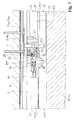
FIG. 1 is a front structural view cutting open main parts above a sliding door, illustrating an example of use of a forward-moving mechanism according to one example of the present invention; -
FIG. 2 is a front structural view enlarging the main parts inFIG. 1 ; -
FIG. 3 is a plan structural view viewed from above the sliding door inFIG. 2 , illustrating the configuration on the side of the receiving member constituting the forward-moving mechanism; -
FIG. 4 is a front structural view illustrating the main parts inFIG. 1 , not cutting open the main body constituting the receiving member constituting the forward-moving mechanism; -
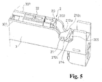
FIG. 5 is a perspective view of the main parts on the side of the receiving member constituting the forward-moving mechanism; -
FIG. 6 is a front structural view cutting open the main parts above a sliding door, illustrating an example of use of the forward-moving mechanism according to the embodiment, wherein the sliding door is in the position at the end of forward movement; -
FIG. 7 is a front structural view enlarging the main parts inFIG. 6 ; -
FIG. 8 is an exploded perspective view of the receiving member constituting the forward-moving mechanism; and -
FIG. 9 is an exploded perspective view of the receiving member constituting the forward-moving mechanism, and illustrates the constituent components in a state having inverted the top, bottom, left, and right inFIG. 8 . - A typical embodiment of this invention is described below based on
FIGS. 1 to 9 . A mechanism for moving a movable body M forward according to the embodiment functions to apply a damping force to a movable body M to be moved forward toward a prescribed position from midcourse of the forward movement up to the prescribed position, to assist that forward movement, or to perform both such application of damping force and such assisting. - Such movable body M is supported to be capable of reciprocating movement on a stationary body S. Examples include sliding doors, hanging doors, folding doors, and the like, but the movable body is not limited to these provided that it is supported to be capable of reciprocating movement on the stationary body S. In the illustrated example, an example is illustrated in which the forward-moving mechanism is used for a sliding door Ma. The sliding door Ma as movable body M is combined on the stationary body S, with an upper end part of the sliding door Ma being held in a rail part Sb provided on the stationary body S provided with an entrance/exit Sa to be opened and closed by the sliding door Ma, so as to perform forward movement and return movement along the rail part Sb.
- In the illustrated example, the sliding door Ma as movable body M closes the entrance/exit Sa at a prescribed position where a front end being at the head during forward movement is struck against a doorstop part Sc of the entrance/exit Sa (
FIG. 6 ). Also, when the sliding door Ma as movable body M is operated to move forward toward the prescribed position from a state not closing the entrance/exit Sa (FIG. 1 ), a received member 1 constituting the forward-moving mechanism contacts with acontact part 20 of a receivingmember 2 constituting the forward-moving mechanism in the course of this forward movement, so that the sliding door is subject to the operation of the forward-moving mechanism up to the prescribed position. In the illustrated example, the received member 1 is provided on the rail part Sb on the side toward the doorstop part Sc at a distance from the doorstop part Sc. - In the illustrated example, such received member 1 is configured as a shaft-form body suspended inside the trench-form rail part Sb with an upper end being fixed to the trench bottom of the rail part Sb. Meanwhile, the receiving
member 2 is provided inside amain body 3 held in a recess Mc formed on the sliding door Ma as movable body M, facing downward from an upper end face of the sliding door Ma. Such recess Mc has a trench form continuing along the direction of movement of the sliding door Ma (the left-right direction inFIG. 1 ), and is opened forward at a front end Mb of the sliding door Ma. In the illustrated example, at midcourse of the forward movement of the sliding door Ma, the received member 1 enters inside the recess Mc, that is, inside themain body 3, from the side of the front end Mb of the sliding door Ma, so as to be brought into contact with the receivingmember 2 inside themain body 3. Also, the sliding door Ma is subject to the operation of the forward-moving mechanism up to the prescribed position by this contact. - In the illustrated example, the receiving
member 2 is held to be movable along the direction of movement of the sliding door Ma inside themain body 3, and is forced by impelling force of a spring 40 constituting an assisting device 4 to perform movement toward the direction away from the front end Mb of the sliding door Ma. Also, damping force of an impelling device 5 is applied to movement of the receivingmember 2 in the direction away from the front end Mb of the sliding door Ma. - In the illustrated example, the receiving
member 2 first is held and stands by against the impelling force of the spring 40 at the side of the front end Mb of the sliding door Ma inside the main body 3 (FIG. 1 / the position of the receivingmember 2 at this time is hereinafter referred to as "advanced position") until being brought into contact with the received member 1; and second, upon being brought into contact with the received member 1, the hold is released and the receiving member catches the received member 1 and is relatively moved forcibly by the impelling force of the spring 40 in the direction away from the front end Mb of the sliding door Ma up to a prescribed retracted position (FIG. 6 ). By this, in the illustrated example, when the sliding door Ma as movable body M is operated to move forward, from the position where the received member 1 contacts with the receivingmember 2, the sliding door Ma moves freely up to the prescribed position where the front end Mb strikes the doorstop part Sc, with the forward movement being assisted by the receivingmember 2 being moved in the aforementioned manner. Also, the free running of the sliding door Ma is slowed by the action of the damping force of the damping device 5 so that the sliding door Ma does not make a loud noise or return toward the opening direction by a return force when colliding with the doorstop part Sc. - When the sliding door Ma as movable body M, thus having been moved forward up to the prescribed position, is operated to move returning, the receiving
member 2 having caught the received member 1 is relatively moved to the side of the front end Mb of the sliding door Ma inside themain body 3 against the impelling force of the spring 40, that is, while accumulating force in the spring 40, and is again held on themain body 3 and releases the received member 1 upon reaching the advanced position. Also, return movement up to a desired position of the sliding door Ma is allowed by this release. - Aside from the illustrated example, even when the received member 1 is attached on the side of the sliding door Ma as movable body M and the
main body 3 containing the receivingmember 2 inside is provided on the side of the stationary body S, the forward movement of such movable body M can be assisted from midcourse. Also, such forward-moving mechanism in the illustrated example acts on the sliding door Ma as movable body M when closing the sliding door Ma, but the forward-moving mechanism can also be used for acting on the sliding door Ma when opening the sliding door Ma. - Specifically, the
main body 3 has a long and slender case form having a width and length sufficient to be housed inside the recess Mc. Themain body 3 is divided into anupper chamber 30 and alower chamber 31. Theupper chamber 30 is opened upward across the length direction of themain body 3, and is opened forward at the front end positioned on the side of the front end Mb of the sliding door Ma. The receivingmember 2 moves between the advanced position and the retracted position inside theupper chamber 30. Theupper chamber 30 is provided with a pair ofwall parts main body 3 and abottom part 302 serving as a partition with thelower chamber 31. Aslit 303 spanning the length direction of themain body 3 is formed on thebottom part 302, and theupper chamber 30 is connected through to thelower chamber 31 via thisslit 303. - The receiving
member 2 has acontact part 20 for contacting with the received member 1, and aholding part 21 in front of thecontact part 20, that moves in the event of collision of the received member 1 on thecontact part 20 and holds the received member 1 from front to back in between with thecontact part 20 to accomplish the catching. - Also, the receiving
member 2 is provided with abase 22 for supporting thecontact part 20 to be capable of sliding movement in the front-back direction, astopper 23 combined on thebase 22 to be capable of sliding movement in the up-down direction, and aspring 24 for regularly impelling thecontact part 20 in the direction of projecting from thebase 22 to the side of the front end Mb of the sliding door Ma, that is, forward. Thebase 22 has a box form open on the front end to accept inside from in front thecontact part 20, which is configured long in the front-back direction, from the rear end side of the contact part. Thestopper 23 is held to be capable of moving up and down inside thecontact part 20 inside thebase 22, and the lower end thereof projects from the lower part of thebase 22. - Also, the
stopper 23 and thecontact part 23 are linked by apin 25 passing throughvertical guide slots 221 formed on side parts in the front-back direction of thebase 22 and passing throughcam slots 201 extending in the front-back direction formed on thecontact part 20. Rear ends 201a of thecam slots 201 are on the same level as lower ends 221a of theguide slots 221, while front ends 201b of thecam slots 201 are on the same level as upper ends 221b of theguide slots 221. In the state in which thecontact part 20 is fully advanced by the impelling force of thespring 24, thepin 25 is positioned at the rear ends 201a of thecam slots 201 and is positioned at the lower ends 221a of theguide slots 221, and thestopper 23 projects downward from the lower part of thebase 22. On the other hand, when thecontact part 20 is retracted against the impelling force of thespring 24, thepin 25 is guided in thecam slots 201 and is moved to the upper ends 221b of theguide slots 221, whereby thestopper 23 is drawn inside thebase 22. - In this example, the holding
part 21 is combined with ashaft 211 on thecontact part 20 to be capable of rotation between a holding position in which the received member 1 is held in between with the contact part 20 (FIG. 7 ) and a non-holding position in which this is not done (FIG. 8 ). - The holding
part 21 is provided with amain part 212 orienting arear face 212a toward afront end 202 of thecontact part 20 in the holding position, a pair ofarm parts main part 212, and an auxiliary catchingpart 214, to be described, formed on the side of afront face 212b of themain part 212. An interval is formed between the pair ofarm parts part 21 is combined with thecontact part 20 in the aforementioned manner, with the lower part of thefront end 202 of thecontact part 20 being received between the pair ofarm parts shaft 211 being passed throughshaft holes arm parts 213 and the lower part of thefront end 202. - In the advanced position of the receiving
member 2, the holdingpart 21 is in a posture in which the side of the lower part thereof is inserted into a receivingspace 33, to be described, formed on themain body 3, so that an interval allowing the received member 1 to pass is formed above the holding part 21 (FIG. 2 / the state in which the holdingpart 21 is in the non-holding position). Also, in the advanced position of the receivingmember 2, the lower end side of thestopper 23 projecting in the aforementioned manner enters into a recessedpart 304 formed on thebottom part 302 of the upper chamber 30 (FIG. 2 ). The receivingmember 2 is held in the advanced position by the entry of thestopper 23 into the recessedpart 304. - The assisting device 4, in the illustrated example, is configured with a tension coil spring 40 held inside the
lower chamber 31 of themain body 3. In the illustrated example, afront end 401 of such spring 40 is fixed to onepart 222 of thebase 22 of the receiving member having entered inside thelower chamber 31 through theslit 303 formed on thebottom part 302 of theupper chamber 30, and arear end 402 of the spring 40 is fixed to the rear end side of thelower chamber 31 of themain body 3, so that the spring 40 is most stretched when the receivingmember 2 is in the advanced position (FIG. 1 ). - The damping device 5, in the illustrated example, are configured with a piston damper 50 provided with a
cylinder 51, apiston 52, and apiston rod 53, so that damping force is applied to movement or relative movement of thepiston 52. In the illustrated example, such piston damper 50 is held between the receivingmember 2 in theupper chamber 30 of themain body 3 and the rear end of theupper chamber 30 with the side of thepiston rod 53 on the front side, the projecting end of thepiston rod 53 being fixed to thebase 22 of the receivingmember 2, and thecylinder 51 being fixed to the side of themain body 3. Also, thepiston rod 53 is most projected from the inside of thecylinder 51 when the receivingmember 2 is in the advanced position (FIG. 1 ). - When the sliding door Ma as movable body M is moved forward, the received member 1 enters inside the
main body 3 from the front end Mb of the sliding door Ma, and the receivingmember 2 in the state being in the advanced position passes above the holding part in the non-holding position and collides with thefront end 202 of thecontact part 20. The receiving member having collided with the received member 1 retracts against the impelling force of thespring 24, the holdingpart 21 is rotated toward the holding position upon this retraction, and the received member 1 is held between thecontact part 20 and the holdingpart 21 and is caught by the receivingmember 2. Also, when thecontact part 20 thus retracts, thestopper 23 is drawn inside thebase 22 and the hold of the receivingmember 2 is released. By this, relative movement of the receivingmember 2 in the direction away from the front end Mb of the sliding door Ma is accomplished by the impelling force of the spring 40, and because the received member 1 provided on the stationary body S is caught by the receivingmember 2, the sliding door Ma is moved forward running freely up to the position where the front end Mb collides with the doorstop part Sc (FIGS. 1 to 6 ). When the sliding door Ma is moved returning from this state, the receivingmember 2 is relatively moved inside themain body 3 in the reverse direction to that during forward movement of the sliding door Ma, and upon reaching the advanced position, entry of thestopper 23 into the recessedpart 304 and advance of thecontact part 20 by thespring 24 are allowed, the holdingpart 21 is pressed by the received member 1 and is rotated to the non-holding position, and release of the received member 1 is accomplished. - In the mechanism for moving a movable body M forward according to this example, because the catching of the received member 1 is accomplished by the movement of the holding
part 21 serving as one part of the receivingmember 2, the space for assuring the movement of the receivingmember 2 can be reduced compared with the case when the catching is accomplished by moving the entire receivingmember 2, as a result of which the required dimensions of the forward-moving mechanism in the direction of this movement (up-down direction in the illustrated example) can be made as small as possible. Also, because the received member 1 is caught while being held from front to back between thecontact part 20 and the holdingpart 21, there is no impediment to the catching even if the distance between thecontact part 20 and the holdingpart 21 is secured wider. Accordingly, even if a shift in a fixed range from a prescribed position occurs to the positions of placements of the received member 1 and the receivingmember 2 in the direction of movement of the movable body M, this shift can be prevented from influencing the operation of the forward-moving mechanism. Also, even if a shift from an expected position occurs to the positions of placements of the received member 1 and the receivingmember 2 in a direction orthogonal to the direction of movement of the movable body M, as long as the range is such that the received member 1 can be held between thecontact part 20 and the holdingpart 21, this shift can be prevented from influencing the operation of the forward-moving mechanism. - In this example, a sliding-
contact part 215 that is slid in contact with aguide part 32 on themain body 3 so as to maintain theposture 21 of the holding part in the holding position is provided in front of the position where the holdingpart 21 is assembled to rotate on thecontact part 20. Also, a receivingspace 33 for receiving the holdingpart 21 of the receivingmember 2 in the advanced position is provided in front of the front end of theguide part 32 on themain body 3. - In the illustrated example, the
bottom part 302 of theupper chamber 30 ends at the position where thefront end 202 of thecontact part 20 of the receivingmember 2 in the advanced position is positioned, which is in front of the recessed part 304 (FIG. 2 ). By this, the receivingspace 33 is formed between the end position of suchbottom part 302 and the front end of themain body 3. - Also, a projecting
part 212c to be guided on the upper end of thewall part 301 of theupper chamber 30 of themain body 3 is formed on the upper part of themain part 212 of the holdingpart 21. Thewall part 201 of theupper chamber 30 of themain body 3 is cut out downward in a position directly above the receivingspace 33, and the projectingpart 212c is positioned in thecutout place 305 in the state in which the holdingpart 21 is in the non-holding position (FIGS. 4 and5 ). - When the receiving
member 2 is relatively moved as previously mentioned from the advanced position toward the retracted position, the projectingpart 212 slips out from thecutout place 305 and is brought into sliding contact on the upper end of thewall part 301 of theupper chamber 30 of themain body 3, and the lower part of thearm part 213 of the holdingpart 21 is brought into sliding contact with thebottom part 302 of theupper chamber 30, the holdingpart 21 is rotated so that thearm part 213 is made to follow thebottom part 302 and therear face 212a of themain part 212 is oriented toward thefront end 202 of thecontact part 20, and that posture is held. That is, in the illustrated example, the upper edge of thewall part 301 of theupper chamber 30 and thebottom part 302 function as theguide part 32, and the projectingpart 212c of the holdingpart 21 and the lower part of thearm part 213 function as the sliding-contact part 215.Such guide part 32 may be either the upper edge of thewall part 301 of theupper chamber 30 or thebottom part 302, and in that case, the sliding-contact part 215 also may be either the projectingpart 212c of the holdingpart 21 or the lower part of thearm part 213 corresponding thereto. - When the movable body M having been moved forward up to the prescribed position is returned and the receiving
member 2 is in the advanced position, entry of thestopper 23 into the recessedpart 203 and advance of thecontact part 20 by thespring 24 are allowed, and the holdingpart 21 is pressed by the received member 1, again enters into the receivingspace 33, and is rotated to the non-holding position, and release of the received member 1 is accomplished. - Also, in this example, an
auxiliary catching part 214, that is elastically deformed to accept the received member 1 by moving the movable body M forward up to the prescribed position when the receivingmember 2 moves to the retracted position in a state not having caught the received member 1 (malfunctioning state), and is coupled to the received member by elastic return in a position at the end of this acceptance, is provided on a front side part on the holdingpart 21 opposite a rear side part facing thecontact part 20, that is, opposite the side of therear face 212a of themain part 212, that is, on the side of thefront face 212b of themain part 212. - In the illustrated example, such
auxiliary catching part 214 is configured with a pair ofelastic pieces part 21. An interval is formed in a direction orthogonal to the direction of movement of the movable body M between such pair ofelastic pieces extended parts 214b are formed respectively on inner face parts of the pair ofelastic pieces front face 212b of themain part 212. Also, the interval between theextended parts 214b on the pair ofelastic pieces extended parts 214b of the pair ofelastic pieces elastic pieces auxiliary catching part 214 by this introduction, and the receivingmember 2 can be returned to the advanced position by moving the movable body M to return thereafter. In the illustrated example, thewall part 301 of theupper chamber 30 of themain body 3 is cut out at the place where theelastic piece 214a of the receivingmember 2 in the retracted position is positioned, and bending outward of the auxiliary catchingpart 214 is made possible by thecutout place 306.
The entire contents of the specification, claims, drawings, and abstract of Japanese Patent Application No.2011-006972 filed on January 17, 2011
Claims (5)
- A mechanism for moving a movable body forward, comprising:a receiving member that is movably held inside a main body provided either on a movable body or on a stationary body supporting the movable body to be capable of reciprocating movement, and is linked to damping device for applying a damping force to forward movement of the movable body to a prescribed position, to an assisting device for moving the movable body forward up to the prescribed position, or to both the damping device and the assisting device; anda received member that is provided on the other of the movable body and the stationary body, is caught on the receiving member in the course of forward movement of the movable body, and is moved or relatively moved inside the main body,wherein the receiving member includes a contact part that contacts with the received member, and a holding part in front of the contact part, that moves in the event of collision of the received member on the contact part and holds the received member from front to back in between with the contact part to accomplish catching.
- The mechanism for moving a movable body forward according to claim 1, wherein the holding part is combined with a shaft on a side of the contact part to be capable of rotation between a holding position in which the received member is held in between with the contact part and a non-holding position in which this is not done.
- The mechanism for moving a movable body forward according to claim 2, wherein a sliding-contact part that slides in contact with a guide part on the main body so as to maintain a posture of the holding part in the holding position is provided in front of a position where the holding part is assembled to rotate on the contact part.
- The mechanism for moving a movable body forward according to claim 3, wherein the receiving member is held inside the main body to be capable of sliding movement between an advanced position and a retracted position for accomplishing catching or releasing of the received member; and
a receiving space for receiving the holding part of the receiving member in the advanced position is provided in front of the front end of the guide part on the main body. - The mechanism for moving a movable body forward according to claim 3, wherein the receiving member is held inside the main body to be capable of sliding movement between an advanced position and a retracted position for accomplishing catching or releasing of the received member; and
an auxiliary catching part, that is elastically deformed to accept the received member by moving the movable body forward up to the prescribed position when the receiving member moves to the retracted position in a state not having caught the received member, and is coupled to the received member by elastic return in a position at the end of this acceptance, is provided on a front side part on the holding part opposite a rear side part facing the contact part.
Applications Claiming Priority (2)
| Application Number | Priority Date | Filing Date | Title |
|---|---|---|---|
| JP2011006972A JP5743563B2 (en) | 2011-01-17 | 2011-01-17 | Moving mechanism of movable body |
| PCT/JP2012/050289 WO2012098953A1 (en) | 2011-01-17 | 2012-01-10 | Forward movement mechanism of movable body |
Publications (1)
| Publication Number | Publication Date |
|---|---|
| EP2666944A1 true EP2666944A1 (en) | 2013-11-27 |
Family
ID=46515584
Family Applications (1)
| Application Number | Title | Priority Date | Filing Date |
|---|---|---|---|
| EP12736994.0A Withdrawn EP2666944A1 (en) | 2011-01-17 | 2012-01-10 | Forward movement mechanism of movable body |
Country Status (4)
| Country | Link |
|---|---|
| EP (1) | EP2666944A1 (en) |
| JP (1) | JP5743563B2 (en) |
| CN (1) | CN103314173A (en) |
| WO (1) | WO2012098953A1 (en) |
Family Cites Families (8)
| Publication number | Priority date | Publication date | Assignee | Title |
|---|---|---|---|---|
| JP4751607B2 (en) * | 2004-12-20 | 2011-08-17 | 株式会社ニフコ | Self-running mechanism, sliding door mechanism, and drawer mechanism |
| JP4726203B2 (en) * | 2005-05-31 | 2011-07-20 | 株式会社ムラコシ精工 | Opening / closing member closing device |
| JP4970116B2 (en) * | 2006-04-20 | 2012-07-04 | 株式会社ニフコ | Self-propelled forward movement mechanism of movable body and sliding door |
| EP2014856A4 (en) * | 2006-04-20 | 2014-03-05 | Nifco Inc | Self-propelled forward movement mechanism of movable body, sliding door, and spacer device |
| JP4970117B2 (en) * | 2006-11-30 | 2012-07-04 | 株式会社ニフコ | Self-propelled forward movement mechanism of movable body |
| JP2008156851A (en) * | 2006-12-21 | 2008-07-10 | Kuriki Manufacture Co Ltd | Sliding door closer |
| JP4402133B2 (en) | 2007-05-18 | 2010-01-20 | アトムリビンテック株式会社 | Sliding door slide assist device |
| JP2010112012A (en) * | 2008-11-04 | 2010-05-20 | Nifco Inc | One-way movement mechanism of movable body |
-
2011
- 2011-01-17 JP JP2011006972A patent/JP5743563B2/en active Active
-
2012
- 2012-01-10 CN CN2012800056241A patent/CN103314173A/en active Pending
- 2012-01-10 EP EP12736994.0A patent/EP2666944A1/en not_active Withdrawn
- 2012-01-10 WO PCT/JP2012/050289 patent/WO2012098953A1/en not_active Ceased
Non-Patent Citations (1)
| Title |
|---|
| See references of WO2012098953A1 * |
Also Published As
| Publication number | Publication date |
|---|---|
| JP2012149390A (en) | 2012-08-09 |
| JP5743563B2 (en) | 2015-07-01 |
| CN103314173A (en) | 2013-09-18 |
| WO2012098953A1 (en) | 2012-07-26 |
Similar Documents
| Publication | Publication Date | Title |
|---|---|---|
| EP2341207A1 (en) | Assist mechanism of movable body | |
| US9708844B2 (en) | Sliding door closing device | |
| EP2354405A1 (en) | Forward movement mechanism of movable body | |
| US8186010B2 (en) | Retracting mechanism and fixing structure | |
| EP2392757A1 (en) | Reciprocation mechanism for rotation body | |
| CN103313627B (en) | For the opening and closing device of movable furniture component | |
| US8668288B2 (en) | Self-closing and opening device particularly for a movable furniture part | |
| KR101933729B1 (en) | Assist device for movable body | |
| JP4970116B2 (en) | Self-propelled forward movement mechanism of movable body and sliding door | |
| WO2007122831A1 (en) | Self-propelled forward movement mechanism of movable body, sliding door, and spacer device | |
| US9885205B2 (en) | Damping device for the damping of the opening movement of a moveable furniture part | |
| JP5726556B2 (en) | Opening and closing body closing device | |
| JP7315715B2 (en) | furniture | |
| KR101973230B1 (en) | Movable object assistance device | |
| JP7086033B2 (en) | Movable body assist device | |
| EP2666944A1 (en) | Forward movement mechanism of movable body | |
| KR20180036511A (en) | Sliding door opening and closing device | |
| WO2012165497A1 (en) | Rotating body assistance device | |
| KR102046665B1 (en) | Assisting mechanism for moveable body | |
| JP2013231278A (en) | Assist mechanism for movable body | |
| JP4726203B2 (en) | Opening / closing member closing device | |
| JP2015067976A (en) | Softly closing device for sliding door | |
| CN104246100A (en) | Auxiliary mechanism of the door | |
| JP3138284U (en) | Sliding door storage furniture with buffer function | |
| JPH0710327U (en) | Guard arm storage state holding device for guard arm lock |
Legal Events
| Date | Code | Title | Description |
|---|---|---|---|
| PUAI | Public reference made under article 153(3) epc to a published international application that has entered the european phase |
Free format text: ORIGINAL CODE: 0009012 |
|
| 17P | Request for examination filed |
Effective date: 20130816 |
|
| AK | Designated contracting states |
Kind code of ref document: A1 Designated state(s): AL AT BE BG CH CY CZ DE DK EE ES FI FR GB GR HR HU IE IS IT LI LT LU LV MC MK MT NL NO PL PT RO RS SE SI SK SM TR |
|
| DAX | Request for extension of the european patent (deleted) | ||
| STAA | Information on the status of an ep patent application or granted ep patent |
Free format text: STATUS: THE APPLICATION HAS BEEN WITHDRAWN |
|
| 18W | Application withdrawn |
Effective date: 20150119 |