EP2666676A1 - Passenger protection apparatus - Google Patents
Passenger protection apparatus Download PDFInfo
- Publication number
- EP2666676A1 EP2666676A1 EP13168876.4A EP13168876A EP2666676A1 EP 2666676 A1 EP2666676 A1 EP 2666676A1 EP 13168876 A EP13168876 A EP 13168876A EP 2666676 A1 EP2666676 A1 EP 2666676A1
- Authority
- EP
- European Patent Office
- Prior art keywords
- airbag
- passenger
- fabric
- seat belt
- webbing
- Prior art date
- Legal status (The legal status is an assumption and is not a legal conclusion. Google has not performed a legal analysis and makes no representation as to the accuracy of the status listed.)
- Granted
Links
- 239000004744 fabric Substances 0.000 claims abstract description 68
- 238000005192 partition Methods 0.000 claims abstract description 48
- 238000003780 insertion Methods 0.000 claims description 9
- 230000037431 insertion Effects 0.000 claims description 9
- 230000004044 response Effects 0.000 claims description 2
- 238000004804 winding Methods 0.000 claims description 2
- 239000000463 material Substances 0.000 description 12
- 230000002093 peripheral effect Effects 0.000 description 10
- 230000000452 restraining effect Effects 0.000 description 8
- 230000000694 effects Effects 0.000 description 6
- 238000009958 sewing Methods 0.000 description 6
- 229920005749 polyurethane resin Polymers 0.000 description 4
- 230000015572 biosynthetic process Effects 0.000 description 3
- 230000037237 body shape Effects 0.000 description 3
- 238000012360 testing method Methods 0.000 description 3
- 150000001336 alkenes Chemical class 0.000 description 2
- 230000008859 change Effects 0.000 description 2
- 238000013461 design Methods 0.000 description 2
- 150000002148 esters Chemical class 0.000 description 2
- JRZJOMJEPLMPRA-UHFFFAOYSA-N olefin Natural products CCCCCCCC=C JRZJOMJEPLMPRA-UHFFFAOYSA-N 0.000 description 2
- 229920005989 resin Polymers 0.000 description 2
- 239000011347 resin Substances 0.000 description 2
- 238000000638 solvent extraction Methods 0.000 description 2
- 230000002123 temporal effect Effects 0.000 description 2
- 229920002725 thermoplastic elastomer Polymers 0.000 description 2
- 238000010521 absorption reaction Methods 0.000 description 1
- 230000009471 action Effects 0.000 description 1
- 230000008901 benefit Effects 0.000 description 1
- 239000003795 chemical substances by application Substances 0.000 description 1
- 238000012790 confirmation Methods 0.000 description 1
- 238000007796 conventional method Methods 0.000 description 1
- 230000001419 dependent effect Effects 0.000 description 1
- 238000001514 detection method Methods 0.000 description 1
- 238000011161 development Methods 0.000 description 1
- 229920001971 elastomer Polymers 0.000 description 1
- 210000001981 hip bone Anatomy 0.000 description 1
- 239000002184 metal Substances 0.000 description 1
- 229920006122 polyamide resin Polymers 0.000 description 1
- 229920001225 polyester resin Polymers 0.000 description 1
- 239000004645 polyester resin Substances 0.000 description 1
- 230000000717 retained effect Effects 0.000 description 1
- 229920002379 silicone rubber Polymers 0.000 description 1
- 239000002759 woven fabric Substances 0.000 description 1
Images



Classifications
-
- B—PERFORMING OPERATIONS; TRANSPORTING
- B60—VEHICLES IN GENERAL
- B60R—VEHICLES, VEHICLE FITTINGS, OR VEHICLE PARTS, NOT OTHERWISE PROVIDED FOR
- B60R21/00—Arrangements or fittings on vehicles for protecting or preventing injuries to occupants or pedestrians in case of accidents or other traffic risks
- B60R21/02—Occupant safety arrangements or fittings, e.g. crash pads
- B60R21/16—Inflatable occupant restraints or confinements designed to inflate upon impact or impending impact, e.g. air bags
- B60R21/18—Inflatable occupant restraints or confinements designed to inflate upon impact or impending impact, e.g. air bags the inflatable member formed as a belt or harness or combined with a belt or harness arrangement
-
- B—PERFORMING OPERATIONS; TRANSPORTING
- B60—VEHICLES IN GENERAL
- B60R—VEHICLES, VEHICLE FITTINGS, OR VEHICLE PARTS, NOT OTHERWISE PROVIDED FOR
- B60R21/00—Arrangements or fittings on vehicles for protecting or preventing injuries to occupants or pedestrians in case of accidents or other traffic risks
- B60R21/02—Occupant safety arrangements or fittings, e.g. crash pads
- B60R21/16—Inflatable occupant restraints or confinements designed to inflate upon impact or impending impact, e.g. air bags
- B60R21/23—Inflatable members
- B60R21/231—Inflatable members characterised by their shape, construction or spatial configuration
- B60R21/233—Inflatable members characterised by their shape, construction or spatial configuration comprising a plurality of individual compartments; comprising two or more bag-like members, one within the other
-
- B—PERFORMING OPERATIONS; TRANSPORTING
- B60—VEHICLES IN GENERAL
- B60R—VEHICLES, VEHICLE FITTINGS, OR VEHICLE PARTS, NOT OTHERWISE PROVIDED FOR
- B60R21/00—Arrangements or fittings on vehicles for protecting or preventing injuries to occupants or pedestrians in case of accidents or other traffic risks
- B60R21/02—Occupant safety arrangements or fittings, e.g. crash pads
- B60R21/16—Inflatable occupant restraints or confinements designed to inflate upon impact or impending impact, e.g. air bags
- B60R21/23—Inflatable members
- B60R21/231—Inflatable members characterised by their shape, construction or spatial configuration
- B60R21/233—Inflatable members characterised by their shape, construction or spatial configuration comprising a plurality of individual compartments; comprising two or more bag-like members, one within the other
- B60R2021/23308—Inflatable members characterised by their shape, construction or spatial configuration comprising a plurality of individual compartments; comprising two or more bag-like members, one within the other the individual compartments defining the external shape of the bag
-
- B—PERFORMING OPERATIONS; TRANSPORTING
- B60—VEHICLES IN GENERAL
- B60R—VEHICLES, VEHICLE FITTINGS, OR VEHICLE PARTS, NOT OTHERWISE PROVIDED FOR
- B60R21/00—Arrangements or fittings on vehicles for protecting or preventing injuries to occupants or pedestrians in case of accidents or other traffic risks
- B60R21/02—Occupant safety arrangements or fittings, e.g. crash pads
- B60R21/16—Inflatable occupant restraints or confinements designed to inflate upon impact or impending impact, e.g. air bags
- B60R21/23—Inflatable members
- B60R21/231—Inflatable members characterised by their shape, construction or spatial configuration
- B60R21/233—Inflatable members characterised by their shape, construction or spatial configuration comprising a plurality of individual compartments; comprising two or more bag-like members, one within the other
- B60R2021/23316—Inner seams, e.g. creating separate compartments or used as tethering means
-
- B—PERFORMING OPERATIONS; TRANSPORTING
- B60—VEHICLES IN GENERAL
- B60R—VEHICLES, VEHICLE FITTINGS, OR VEHICLE PARTS, NOT OTHERWISE PROVIDED FOR
- B60R21/00—Arrangements or fittings on vehicles for protecting or preventing injuries to occupants or pedestrians in case of accidents or other traffic risks
- B60R21/02—Occupant safety arrangements or fittings, e.g. crash pads
- B60R21/16—Inflatable occupant restraints or confinements designed to inflate upon impact or impending impact, e.g. air bags
- B60R21/23—Inflatable members
- B60R21/231—Inflatable members characterised by their shape, construction or spatial configuration
- B60R21/233—Inflatable members characterised by their shape, construction or spatial configuration comprising a plurality of individual compartments; comprising two or more bag-like members, one within the other
- B60R2021/23324—Inner walls crating separate compartments, e.g. communicating with vents
-
- B—PERFORMING OPERATIONS; TRANSPORTING
- B60—VEHICLES IN GENERAL
- B60R—VEHICLES, VEHICLE FITTINGS, OR VEHICLE PARTS, NOT OTHERWISE PROVIDED FOR
- B60R21/00—Arrangements or fittings on vehicles for protecting or preventing injuries to occupants or pedestrians in case of accidents or other traffic risks
- B60R21/02—Occupant safety arrangements or fittings, e.g. crash pads
- B60R21/16—Inflatable occupant restraints or confinements designed to inflate upon impact or impending impact, e.g. air bags
- B60R21/23—Inflatable members
- B60R21/231—Inflatable members characterised by their shape, construction or spatial configuration
- B60R21/2334—Expansion control features
- B60R21/2338—Tethers
- B60R2021/23382—Internal tether means
Definitions
- the present invention generally relates to a passenger protection apparatus and, more particularly, to a passenger protection apparatus configured such that the sufficient tensile force of a seat belt is ensured in an initial inflation stage of an airbag folded like a belt and provided at the position of a shoulder belt when the airbag is inflated upon the detection of a vehicular collision to extend from the chest part to a shoulder part of the passenger, and that subsequent deformation of the airbag enables the passenger protection apparatus to effectively restrain the passenger.
- the assignee of the present application developed a passenger protection apparatus (hereinafter referred to as an airbelt apparatus) configured such that an airbag housed in a shoulder belt of a seat belt is inflated around a portion extending from the chest part to a shoulder upper part of a passenger and that a single manufactured airbelt apparatus can deal with two accident modes, i.e., a frontal collision and a lateral collision (see Takata Corporation, "Vehicular Safety System Maker Takata Corporation Exhibits Airbelt at Good Design Exposition (EXPO) 2011", August 24, 2011, http:www.takata.com/pdf/110824_JP.pdf ).
- This airbelt apparatus is such that the airbag is inflated along the shoulder belt worn by the passenger so as to have a substantially spindle shape thereby to increase the contact area between the airbag and the chest part of the passenger and to disperse and alleviate impact to be imposed on the chest part.
- this airbelt apparatus is provided with two retractors that respectively wind a lap-belt-side part of the seat belt with respect to a tongue fixed to the seat belt and a shoulder-belt-side part of the seat belt, which houses the airbag as an airbelt, with respect to the tongue. Consequently, cost is high. Thus, this airbelt apparatus is assumed to be mounted in a luxury car or the like.
- the assignee advances the development of another airbelt apparatus configured such that a shoulder belt into which an airbelt is incorporated and a lap belt provided opposite to the shoulder belt with respect to a tongue plate can be drawn from and wound into a single retractor.
- a single retractor it is necessary to configure the airbelt apparatus such that when a piece of webbing is drawn out of the retractor, an airbelt part (i.e., a part of the shoulder belt) having a tongue provided with a tongue plate and a gas supply port at an end portion thereof can smoothly slide against the webbing to an appropriate position between the chest part and the shoulder part, in addition to the drawing of a predetermined amount of the lap belt.
- JP-A-2001-260807 discloses an airbelt apparatus configured to solve the above problem and to enable that webbing is surely wound using only a single retractor.
- the airbelt apparatus disclosed in JP-A-2001-260807 is such that a bag assembly 7 formed substantially-flat accommodates, in a cover formed with warp-knitted knit-fabric, the webbing 4 and an airbag in which a gas passage 22a and a four elongated gas chambers 22b are formed in parallel.
- the airbelt apparatus disclosed in JP-A-2001-260807 is such that such that, e.g., upon collision, the above four gas chambers 22b are inflated so as to have four substantially-cylindrical shapes connected together in longitudinal direction (see FIG. 8 of JP-A-2001-260807 ).
- the knitted cover 21 is also radially stretched (at the webbing-side) and longitudinally deflates (at the gas-chamber-side) to thereby give an initial tensile force to a shoulder belt part.
- a base plate 25 is inserted into the bag assembly 7 in order to prevent the airbag from being damaged when the airbag is folded.
- each gas chamber of this airbag is divided only by seams, as illustrated in FIG. 9 of JP-A-2001-260807 , and covered with the cover 21 which stretches radially freely. Therefore, only the two inner gas chambers are deformed by a force applied from the webbing.
- the gas chambers 22b provided at both longitudinal-ends can hardly receive the applied-force. Accordingly, there is a risk that the airbelt cannot sufficiently obtain the advantage of protecting the chest part of the passenger.
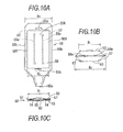
- FIGS. 10A to 10C and FIGS. 11A and 11B of this invention The configuration of an airbag 50 of this apparatus is described with reference to each of FIGS. 10A to 10C.
- FIG. 10A is a developed plan view of the airbag 5 0.
- the airbag 50 is configured by a fabric member formed by sewing base fabrics, each of which is cut out into an elongated shape of a predetermined dimension, like a predetermined bag provided with a gas supply port 50a at one end thereof, utilizing an outer peripheral seam 57 which forms an outer peripheral shape of the airbag 50 slightly inside of an outer peripheral edge 50b, and two row of partitioning seams 58a formed along a longitudinal direction inside of the outer peripheral seam 57.
- slits 55a and 55b are formed at the nearly center in a width direction of the airbag 50 and at locations sufficiently away from each other along the longitudinal direction.
- the airbag 50 is partitioned into three partitions 50A, 50B, and 50C by the partitioning seams 58a formed along the longitudinal direction.
- the partitions 50A, 50B and 50C are inflated substantially simultaneously with one another into three substantially cylindrical shapes formed in parallel (see 50A, 50B, and 50C in FIG. 11A ).
- both end portions of each of tethers 53 illustrated in FIG. 10B are stacked on a corresponding one of both surfaces of the airbag 50. Then, the end portions of the tethers 53 and the airbag 50 are sewed in a superimposed manner integrally with one another along positions on the outer peripheral seam formed in the longitudinal direction of the airbag 50 so that the tethers 53 cover the outer surface of an airbag body. As illustrated in FIG. 10B , the width B1 of each tether 53 is set to be slightly shorter than that B2 of the developed airbag 50.
- the airbag 50 when the airbag 50 is inflated, the outer peripheral surface of the airbag 50 having three cylindrical partitions inflated in parallel is restrained by the tight tethers 53 from being inflated in an outer peripheral direction. Consequently, the airbag 50 is such that the three cylindrical partitions 50A, 50B and 50C are arranged in parallel in the airbag 50, and that the airbag 50, whose outer surface has a shape limited by the tethers 53 provided on the surface of the airbag 50, is inflated into a shape close to the shape of a substantially-flat-surface inflatable member (see FIG. 11A ).
- the airbag 50 having the width B2 and the narrow tethers 53 having the width B1 are sewed together by adjusting both ends in the width direction of the airbag 50 to those in the width direction of each of the tethers 53, respectively.
- tucks (i.e., folding margins) 54 each having a predetermined width in a longitudinal direction are ensured and folded to thereby adjust the width of the airbag 50 to the width B1 of the tethers 53.
- the airbag 50 and the tethers 53 are sewed integrally with one another (see FIG. 10C ).
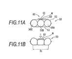
- FIG. 11A illustrates a state of the airbag 50 serving as an airbelt just after the airbag 50 is completely inflated at the position of, e.g., the chest part of a passenger upon a collision.
- FIG. 11B with the retraction of webbing W caused by an operation of a pretensioner, and with the forward movement (corresponding to an upward direction in FIG. 11B ) of the passenger, a force directed in the direction of an arrow acts upon the webbing W that relatively movably holds the belt. Consequently, with the movement in the direction of the arrow of the webbing W, the airbag 50 is deformed, as illustrated in FIG. 11B .
- the webbing W pushes a part of the tether 53 provided on the airbag 50 through a flexible sheet 62 of a slide guide 60.
- the tethers 53 are pushed only at that part.
- the three partitions 50A, 50B and 50C of the airbag 59 whose substantially flat shape is retained by the tethers 53 are deformed around the central partition 50B.
- the circular cross-section of each of the both side partitions 50A and 50C is deformed by following the deformation of each of the tethers 53 and the central partition 50B.
- the passenger-side surface of the airbag 50 maintains a state in which the passenger-side surface is closely attached to the passenger over a width B3. Consequently, a pressing force applied to a portion extending from the chest part to a shoulder part of the passenger can be dispersed to a wide range.
- the above airbelt apparatus provided with the airbag having the three cylinder partitions can solve the problem which the airbelt apparatus disclosed in JP-A-2001-260807 , i.e., the ensuring of a tensile force in an initial stage of an operation of the seat belt, by configuring the airbelt apparatus so as to add the tethers to the airbag.
- the airbelt apparatus in order to ensure a further larger tensile force of the seal belt in an initial inflation stage (i.e., to increase the distance between the webbing and the passenger), it is necessary to increase the diameter of each inflated cylindrical partition of the airbag.
- an object of the invention is to solve the problems which the above conventional techniques have, and to provide a passenger protection apparatus configured such that when an airbag provided on a shoulder belt by being folded like a belt is inflated, a sufficient initial tensile force of a seat belt is ensured by a simple configuration of the airbag in an initial stage of a passenger protection operation using the seat belt and the airbag added to the seat belt, and that a passenger can be protected gently and effectively by the subsequent deformation of the airbag.
- the present invention provides a passenger protection apparatus as defined in claim 1.
- the dependent claims define preferred embodiments of the invention.
- a seat belt is wound up by a single winding device in a passenger protection apparatus.
- An airbag configured to be inflatable in response to a predetermined actuating signal is provided at a position of a shoulder belt of the seat belt by being folded like a belt in the passenger protection apparatus.
- the passenger protection apparatus includes a fabric member and a partition wall fabric.
- the fabric member configures a bag-like member of the airbag.
- the partition wall fabric has portions respectively connected to a first part and a second part of the fabric member and partitions an inside of the bag-like member into a central inflatable portion and supporting inflatable portions each of which is located between a passenger-side surface of the fabric member and a fabric formed of the central inflatable portion.
- the first and second parts configure inner surface of the bag-like member.
- the first and second parts hold the seat belt.
- the second part is configured to face a passenger and configured to be opposite to the first part.
- the central inflatable portion is inflated to be supported by the supporting inflatable portions, so that a tensile force of the seat belt is maintained.
- the supporting inflatable portions are then deformed substantially flat so as to restrain the passenger.
- both ends of the partition wall fabric are sewed to the first part of the fabric member in a direction along the seat belt.
- a central part between the both ends of the partition wall fabric is sewed to the second part of the fabric member, so that the inside of the bag-like member is partitioned into the central inflatable portion and the supporting inflatable portions.
- the partition wall fabric and a fabric member that configures an insertion passage through which the seat belt passes are integrally sewed to the first part.
- a part of the partition wall fabric, which is partitioned into the central inflatable portion and the supporting inflatable portions, is formed between two slits which allows the airbag to slide on the seat belt by passing through the two slits.
- the passenger protection apparatus serving as an airbelt apparatus limits the shape of the airbag mounted on the seat belt to a predetermined shape of the inflated airbag.
- the tensile force of the seat belt can be maintained at high levels.
- the airbag is deformed. Consequently, the upper body part of a passenger can gently and effectively be restrained and protected.
- FIG. 1 is a perspective explanatory view schematically illustrating a state in which a passenger protection apparatus 10 according to the invention (also referred to as an airbelt apparatus 10, hereinafter) is equipped on a passenger seat 1.
- FIG. 1 illustrates a state in which a seat belt 3 drawn out of a retractor 2 is folded back at a tongue 4 and in which an end portion of the seat belt 3 is fixed to an anchor plate 6.
- the anchor plate 6 is fixed to a stationary part (not shown) of a vehicle body (not shown).
- the expression "seat belt” is used as a term used in the case of restraining a passenger, performing the functions of the seat belt, and indicating a part, e.g., a shoulder belt.
- a woven fabric belt member which is wound up by and drawn out from the retractor by a predetermined drawing force is hereinafter referred to as "webbing".
- the retractor 2 illustrated in FIG. 1 is designed to be housed in and fixed to a vehicle-body-side part, e.g., a B-pillar, a C-pillar, and a tray in rear of a rear seat, or a part of a seat in a seat back 1B, corresponding to a seat on which the retractor 2 is equipped.
- the webbing W is in a state in which the webbing W is wound up by the retractor 2 by maintaining a predetermined tensile force at the side of the seat just after a passenger is seated.
- the webbing W is parted into a shoulder belt 3S and a lap belt 3L at the position of the tongue 4.
- the part of the webbing W, which serves as the lap belt 3L is ensured by drawing the webbing W out of the retractor 2 and pulling the tongue 4 to a buckle 9, as illustrated in FIG. 1 .
- the passenger grabs the webbing W placed beside the passenger, and draws the webbing W out of the retractor 2.
- This position of the tongue 4 corresponds to an end of an airbelt 11 accommodating a folded airbag 20.
- the airbag 20 configuring the airbelt 11 ensures a sufficient space between the passenger and the webbing W when the airbag 20 is initially inflated.
- a shoulder anchor 7 is installed at the top of the right-shoulder-side part of the seat back 1B.
- the shoulder anchor 7 is provided at an upper part of the B-pillar or the top of the seat back 1B.
- the shoulder belt 3S is led to the retractor 2 by being turned around at the shoulder anchor 7.
- the airbelt 11 whose configuration is described in detail below, is attached to the part of the webbing W, which serves as the shoulder belt 3S.
- the tongue 4 is shaped integrally with a through anchor 8.
- a gas supply pipe 4a is provided in juxtaposition with a tongue plate 4b.
- the gas supply pipe 4a is a metallic tubular member.
- a gas supply path (not shown) provided in the tongue 4 to communicate with the gas supply pipe 4a is airtightly connected to a gas introducing port 20a of the airbag 20 illustrated in FIG. 3 .
- FIG. 1 also illustrates a buckle 9 holding the gas supply pipe 4a and the tongue plate 4b of the tongue 4.
- the buckle 9 is fixed via a bracket 9a through a fixing member, such as bolts, to a stationary part (not shown) of a vehicle body, which is provided beside the seat.
- a tongue plate supporting hole 9b and a gas supply pipe connecting hole 9c are formed in the buckle 9.
- the tongue plate 4b and the gas supply pipe 4a are simultaneously inserted into the holes 9b and 9c of the buckle 9, respectively.
- a gas exhaust nozzle (not shown) of the inflator G externally attached to the buckle 9 is made to communicate with the connecting hole 9c into which the gas supply pipe 4a is inserted.
- the airbag 20 (see FIG. 3 ) is inflated along the shoulder belt 3S worn by the passenger so as to have a cross-sectional shape partitioned by partition-walls 41 into plural partitions respectively having predetermined cross-sectional shapes (see FIG. 4B ). Then, with increase of the tensional force of the belt due to the forward movement of the passenger, inflatable portions respectively corresponding to the plural partitions are deformed into a substantially flat thickness surface shape (see FIG. 4C ).
- the passenger's lateroabdominal part, chest part, and shoulder upper part can gently be restrained (see FIGS. 4C , 5B , and 1 (the shape of the inflated airbelt is indicated by imaginary lines in FIG. 1 )).
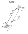
- FIG. 2 is an external view illustrating the airbelt 11 fit onto the part of the webbing W, which corresponds to the shoulder belt 3S.
- the airbelt 11 illustrated in FIG. 2 is configured such that the full-width airbag 20 illustrated in FIG. 4A is folded to have an elongated shape whose width is substantially adjusted to the width of the webbing W, using the webbing W placed in the airbelt 11 as a core member, and then covered with an exterior cover 21.
- the exterior cover 21 is made by sewing a fabric like a cylinder.
- Opening guide rings 22 made of polyurethane resin are attached to opening portions provided at both ends of the exterior cover 21.
- the opening guide rings 22 are high in stiffness. Therefore, the opening guide rings 22 are difficult to deform. Due to the substantially flat shape of the openings, the webbing W can be maintained in a substantially flat state. In addition, the sliding resistance between the webbing W and the airbelt 11 is reduced. Consequently, when the seat belt is fastened, the airbelt 11 can smoothly slide along the webbing W.
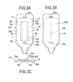
- FIG. 3A is a plan view illustrating a state of the top surface (corresponding to a vehicle-interior side which is a first part side) of the airbag 20 before folded.
- FIG. 3B is a plan view illustrating a state of the bottom surface (corresponding to a passenger side which is a second part side) of the airbag 20 before folded.
- FIG. 3C is a cross-sectional view illustrating the fabrics with lines.
- the airbag 20 is a fabric member formed by sewing base fabrics, each of which is cut out into an elongated shape of a predetermined dimension, like a predetermined bag provided with a gas supply port 20a at one end thereof, utilizing an outer peripheral seam 27 which forms an outer peripheral shape of the airbag slightly inside of an outer peripheral edge 20b.
- slits 25a and 25b are formed at the nearly center in a width direction of the airbag 20 and at locations sufficiently away from each other along the longitudinal direction.
- One 25b of the slits is formed in an inflatable region of the airbag 20. Thus, a region for preventing leakage of air is formed around the slit 25b.
- the front surface fabric 20A has one side surface (i.e., an outer surface in this embodiment) to which a passage formation fabric piece 20C is sewed using two seams 28a extending in the longitudinal direction.
- a space 29 between the passage formation fabric piece 20C and the front surface fabric 20A serves as an insertion passage (hereinafter also designated with reference numeral 29) through which the webbing W is inserted.
- a partition wall fabric piece 20D is sewed to the front surface fabric 20A and the back surface fabric 20B so as to be put therebetween.
- the partition wall fabric piece 20D is configured by a fabric which has substantially the same shape as the shape of the passage formation fabric piece 20C and is made of the same material.
- the partition wall fabric piece 20D is sewed to the inner surface of the partition wall fabric piece 20D at both ends thereof.
- a central portion of the partition wall fabric piece 20D is sewed to the back surface fabric 20B (see FIG. 3B ).
- airtightness may be enhanced by sewing and bonding the fabric pieces together.
- FIG. 4A illustrates a state in which the webbing W is inserted into a webbing insertion passageway (hereinafter also designated with reference numeral 29) configured by the insertion passage 29 illustrated in FIG. 3C , a gate-shaped guide 35, and a flexible sheet 32 (described below), so that the webbing W is mounted in the apparatus.
- a webbing insertion passageway hereinafter also designated with reference numeral 29
- a gate-shaped guide 35 configured by the insertion passage 29 illustrated in FIG. 3C
- a flexible sheet 32 described below
- the airbag 20 When gas is supplied into the airbag 20 by causing, at collision or the like, the inflator G to operate in this state, the airbag 20 supports the webbing insertion passageway 29 by the top side-surface portion thereof, as illustrated in FIG. 4B , in an initial stage (i.e., within an elapsed time range of 0 to 20 milli-seconds (msec)).
- the airbag 20 is inflated so as to have a cross-sectional shape including a cross-sectionally substantially-isosceles-triangular shaped central inflatable portion 40 whose two surfaces function as partition walls 41, and two supporting inflatable portions 42 each of which is partitioned from the central inflatable portion 40 by an associated one of the partition walls 41 respectively corresponding to the cross-sectionally equilateral sides.
- the ratio of the cross-sectional area of the central inflatable portion 40 to the cross-sectional area of each of the supporting inflatable portion 42 is set at about 60%.
- the central inflatable portion 40 is supported on the supporting inflatable portions 42.
- About 90 millimeters (mm) is ensured as the distance H1 from the passenger-side surface (i.e., the bottom-surface-side surface) to the webbing W in the webbing insertion passageway 29.
- the height H2 from the passenger-side surface to the webbing W is reduced to about 60% of the height H1 illustrated in FIG. 4B .
- the width of a part of the inflatable portions 42, which is contacted with the passenger, is increased from L1 (e.g., 80mm) in the state illustrated in FIG. 4B to L2 (e.g., about 1.75 times to 2.0 times the width L1) in the state illustrated in FIG. 4C .
- FIGS. 5A and 5B are schematic perspective views each illustrating a state in which the effects of restraining a passenger by the airbelt illustrated in FIG. 2 are confirmed by conducting a test using a dummy-passenger.
- FIG. 5A illustrates a state in the case of restraining and protecting a dummy-passenger using the airbelt 11 configured by the airbag 20 having a cross-sectional shape illustrated in FIG. 4B .
- FIG. 5B illustrates a state in the case of restraining and protecting a dummy-passenger using the airbelt 11 configured by the airbag 20 having a cross-sectional shape illustrated in FIG. 4C .
- FIG. 4C illustrates a state in which the effects of restraining a passenger by the airbelt illustrated in FIG. 2 are confirmed by conducting a test using a dummy-passenger.
- FIG. 5A illustrates a state in the case of restraining and protecting a dummy-passen
- the central inflatable portion 40 supporting the webbing W is supported by the supporting inflatable portions 42 and held at a position away from the dummy-passenger.
- the tensile force initially introduced to the webbing W was maintained at a high level even in the initial stage, as compared with the tensile force in the case of the airbelt apparatus illustrated in FIG. 10A to 10C . It was found that since then, the tensile force initially introduced to the webbing W was maintained to be relatively high, as compared with the tensile force in the case of the airbelt apparatus illustrated in FIG. 10A to 10C .
- FIG. 6 is a graph illustrating temporal change of the tensile force of the webbing, which was found for a period of time elapsed since the inflator was operated (i.e., an elapsed time of inflation of the airbag), at the test using the dummy-passenger.
- the airbelt apparatus according to the invention could maintain the tensile force of the webbing W to be about twice the tensile force in the case of the conventional airbelt apparatus having three cylindrical partitions (incidentally, FIGS. 11A and 11B illustrate cross-sectional shapes of the airbelt apparatus cited as a conventional product), and that effects of highly restraining the dummy-passenger could be obtained.
- a row of a large number of gate-shaped guides 35 serving as high-stiffness parts illustrated in FIG. 7A is provided in a length direction of the flexible sheets 32 serving as low-stiffness parts so that the webbing W smoothly moves, similarly to the apparatus disclosed by the above application.
- the gate-shaped guide 35 is shaped like a substantially flat inverted-U whose inner dimension of is slightly larger than the width of the webbing W and whose dimension in a length direction is about 1.5 centimeters (cm).
- the gate-shaped guide 35 is welded to the flexible sheet 32 at the bottom thereof.
- the gate-shaped guide 35 has high stiffness in the width direction of the webbing W.
- the distance between the gate-shaped guides 35 adjoining in the longitudinal direction of the webbing W is set to be equal to or less than 1 cm, as illustrated in FIG. 7B .
- a row of a large number of gate-shaped guides 30 is provided in the length direction of the flexible sheet 32 serving a low-stiffness part.
- a polyurethane resin is used as the resin material configuring the guides.
- thermoplastic elastomers e.g., ester-based ones, and olefin-based ones
- polyamide resins e.g., polyamide resins, rigid polyurethane resins, polyester resins, metal plates and the like can be used as appropriate materials of the guide.
- the flexible sheet 32 is an elongated flexible plate-like member which is substantially equal in width to the webbing W.
- the flexible sheet 32 fixed to a range in a longitudinal direction of the webbing insertion passageway 29 illustrated in FIG. 3A by bonding or sewing.
- the surface of the flexible sheet 32 is smoothly finished.
- thermoplastic elastomers e.g., ester-based ones and olefin-based ones
- the resin material configuring the flexible sheet 32 are used as the resin material configuring the flexible sheet 32.
- flexible polyurethane resins, silicon elastomers, rubber materials (e.g., synthetic ones, and natural ones), and the like can be used as the appropriate materials of the flexible sheet 32.
- the functions of the slide guide 30 can be fulfilled by using the same material as the materials of the above gate-shaped guide 35 and the above flexible sheet 32 and designing the gate-shaped guide 35 and the flexible sheet 32 so as to differ in shape (e.g., thickness, and width) to thereby bring out the difference in stiffness.
- the back surface fabric 20B and the partition wall fabric piece 20D of the airbag 20 can be sewed using a single linear seam 28b, as illustrated in FIG. 3B .
- the airbag 20 when the airbag 20 is actually inflated, the inflation of the airbag 20 is suppressed at the position of the seam, whereas a part surrounding each end portion of the seam is rapidly inflated. Accordingly, stress concentration occurs at the end portions of the seam.
- this problem can be eliminated by forming a semicircular seam 28c so as to be continuous to each end portion of the seam, as illustrated in FIG. 3A .
- FIGS. 8A and 8D illustrate other examples of the shape of each seam.
- FIG. 8A illustrates an example of first providing two seams so as to be separated from each other at a distance of about 10mm, and then forming a semicircular seam 28c to continuously connect end portions at each of both sides in the longitudinal direction of the two seams.
- the airbag 20 is shaped in the initial inflation stage such that the supporting inflatable portions 42 each partitioned from the central inflatable portion 40 are separated from each other at a width D, as illustrated in FIG. 8C .
- the webbing W is held at a position sufficiently separated from a passenger.
- a ring-like seam 28r serving as a stress relaxation portion is provided at each end portion of the single linear seam 28b.
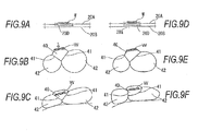
- FIGS. 9A to 9F illustrate other examples of the dimensions and the attachment position of the partition wall fabric piece 20D.
- the airbag 20 of the airbelt 11 according to the invention is set such that the partition wall fabric piece 20D is arranged at the central position in the width direction of the airbag 20, and that the cross-sectional shape of the airbag 20 in the inflation stage is symmetric with respect to the width direction.
- passengers have various body shapes.
- the airbag of the airbelt apparatus is inflated so as to be fit to the body shape, especially, the shape of the front surface of the body of the passenger.
- the webbing insertion passageway 29 and the partition wall fabric piece 20D are shifted from the center position in the width direction of the airbag 20 to make the capacities (thus, the cross-sectional areas) of the supporting inflation portions 42 differ from each other. Consequently, a position at which the seat belt restrains the passenger, and a direction in which the belt presses down the passenger can be controlled.
- the airbag 20 is inflated in a state in which the supporting inflatable portions 42 provided on the left and right sides of the central inflatable portion 40 differing in cross-sectional area from each other.
- the direction in which the webbing W acts to restrain the passenger can be inclined according to the body shape of the passenger. Consequently, effects of restraining the passenger become more reliable.
- the tensile force of the webbing W is more increased due to the forward movement of the passenger.
- the airbag becomes substantially flat according to the shape of a part of the airbag 20, which is contacted with the passenger, becomes substantially flat (see FIG. 9C ).
- FIG. 9D illustrates an example of providing the airbag by shifting, from the center position in the width direction, the position at which the partition wall fabric piece 20D and the back surface fabric 20B of the airbag 20 are contacted with each other.
- a cross-sectional side length of the partition wall 41 between the central inflatable portion 40 and one of the supporting inflatable portions 42 differs from a cross-sectional side length of the partition wall 41 between the central inflatable portion 40 and the other supporting inflatable portion 42. Consequently, effects substantially equivalent to the effects obtained in the state illustrated in each of FIG. 9B and FIG. 9C can be obtained even in an associated one of the initial inflation stage illustrated in FIG. 9E and the state of the airbag 20 deformed by the tensile force of the webbing W, which is illustrated in FIG. 9F .
- the material of the partition wall fabric piece 20D is the same as that of the base fabric of the airbag.
- the shape of the airbag can variously be controlled according to the partition wall fabric piece by diversely changing the material. Even in the case of configuring the airbag by making the material of the passenger-side surface to differ from the material of the webbing-side surface, obviously, the shape of the inflated airbag can be changed.
- the present invention is not limited to the above embodiments, and can variously be modified within a range described in the appended-claims. That is, embodiments obtained by combining technical means appropriately changed within the range described in the appended-claims are also included in the technical scope of the invention.
Landscapes
- Engineering & Computer Science (AREA)
- Mechanical Engineering (AREA)
- Air Bags (AREA)
Abstract
Description
- The present invention generally relates to a passenger protection apparatus and, more particularly, to a passenger protection apparatus configured such that the sufficient tensile force of a seat belt is ensured in an initial inflation stage of an airbag folded like a belt and provided at the position of a shoulder belt when the airbag is inflated upon the detection of a vehicular collision to extend from the chest part to a shoulder part of the passenger, and that subsequent deformation of the airbag enables the passenger protection apparatus to effectively restrain the passenger.
- The assignee of the present application developed a passenger protection apparatus (hereinafter referred to as an airbelt apparatus) configured such that an airbag housed in a shoulder belt of a seat belt is inflated around a portion extending from the chest part to a shoulder upper part of a passenger and that a single manufactured airbelt apparatus can deal with two accident modes, i.e., a frontal collision and a lateral collision (see Takata Corporation, "Vehicular Safety System Maker Takata Corporation Exhibits Airbelt at Good Design Exposition (EXPO) 2011", August 24, 2011, http:www.takata.com/pdf/110824_JP.pdf).
- This airbelt apparatus is such that the airbag is inflated along the shoulder belt worn by the passenger so as to have a substantially spindle shape thereby to increase the contact area between the airbag and the chest part of the passenger and to disperse and alleviate impact to be imposed on the chest part.
- However, this airbelt apparatus is provided with two retractors that respectively wind a lap-belt-side part of the seat belt with respect to a tongue fixed to the seat belt and a shoulder-belt-side part of the seat belt, which houses the airbag as an airbelt, with respect to the tongue. Consequently, cost is high. Thus, this airbelt apparatus is assumed to be mounted in a luxury car or the like.
- On the other hand, the assignee advances the development of another airbelt apparatus configured such that a shoulder belt into which an airbelt is incorporated and a lap belt provided opposite to the shoulder belt with respect to a tongue plate can be drawn from and wound into a single retractor. However, in the case of using the single retractor, it is necessary to configure the airbelt apparatus such that when a piece of webbing is drawn out of the retractor, an airbelt part (i.e., a part of the shoulder belt) having a tongue provided with a tongue plate and a gas supply port at an end portion thereof can smoothly slide against the webbing to an appropriate position between the chest part and the shoulder part, in addition to the drawing of a predetermined amount of the lap belt.
-
JP-A-2001-260807 JP-A-2001-260807 - Meanwhile, the airbelt apparatus disclosed in
JP-A-2001-260807 FIG. 8 ofJP-A-2001-260807 cover 21 is also radially stretched (at the webbing-side) and longitudinally deflates (at the gas-chamber-side) to thereby give an initial tensile force to a shoulder belt part. At that time, a base plate 25 is inserted into the bag assembly 7 in order to prevent the airbag from being damaged when the airbag is folded. Thus, upon collision, the webbing 4 acting to restrain the passenger pushes only the inner two of the four gas chambers 22b. Each gas chamber of this airbag is divided only by seams, as illustrated inFIG. 9 ofJP-A-2001-260807 cover 21 which stretches radially freely. Therefore, only the two inner gas chambers are deformed by a force applied from the webbing. The gas chambers 22b provided at both longitudinal-ends can hardly receive the applied-force. Accordingly, there is a risk that the airbelt cannot sufficiently obtain the advantage of protecting the chest part of the passenger. - In order to solve this problem, the assignee of the present application has proposed a passenger protection apparatus disclosed in each of
FIGS. 10A to 10C andFIGS. 11A and 11B of this invention. The configuration of anairbag 50 of this apparatus is described with reference to each ofFIGS. 10A to 10C. FIG. 10A is a developed plan view of theairbag 5 0. Theairbag 50 is configured by a fabric member formed by sewing base fabrics, each of which is cut out into an elongated shape of a predetermined dimension, like a predetermined bag provided with agas supply port 50a at one end thereof, utilizing an outerperipheral seam 57 which forms an outer peripheral shape of theairbag 50 slightly inside of an outerperipheral edge 50b, and two row of partitioningseams 58a formed along a longitudinal direction inside of the outerperipheral seam 57. In addition,slits airbag 50 and at locations sufficiently away from each other along the longitudinal direction. Theairbag 50 is partitioned into threepartitions partitioning seams 58a formed along the longitudinal direction. When gas is introduced to each of thepartitions partitions FIG. 11A ). - When the
airbag 50 is sewed, both end portions of each oftethers 53 illustrated inFIG. 10B are stacked on a corresponding one of both surfaces of theairbag 50. Then, the end portions of thetethers 53 and theairbag 50 are sewed in a superimposed manner integrally with one another along positions on the outer peripheral seam formed in the longitudinal direction of theairbag 50 so that thetethers 53 cover the outer surface of an airbag body. As illustrated inFIG. 10B , the width B1 of eachtether 53 is set to be slightly shorter than that B2 of thedeveloped airbag 50. Thus, when theairbag 50 is inflated, the outer peripheral surface of theairbag 50 having three cylindrical partitions inflated in parallel is restrained by thetight tethers 53 from being inflated in an outer peripheral direction. Consequently, theairbag 50 is such that the threecylindrical partitions airbag 50, and that theairbag 50, whose outer surface has a shape limited by thetethers 53 provided on the surface of theairbag 50, is inflated into a shape close to the shape of a substantially-flat-surface inflatable member (seeFIG. 11A ). Incidentally, theairbag 50 having the width B2 and thenarrow tethers 53 having the width B1 are sewed together by adjusting both ends in the width direction of theairbag 50 to those in the width direction of each of thetethers 53, respectively. Thus, tucks (i.e., folding margins) 54 each having a predetermined width in a longitudinal direction are ensured and folded to thereby adjust the width of theairbag 50 to the width B1 of thetethers 53. Then, theairbag 50 and thetethers 53 are sewed integrally with one another (seeFIG. 10C ). -
FIG. 11A illustrates a state of theairbag 50 serving as an airbelt just after theairbag 50 is completely inflated at the position of, e.g., the chest part of a passenger upon a collision. Then, as illustrated inFIG. 11B , with the retraction of webbing W caused by an operation of a pretensioner, and with the forward movement (corresponding to an upward direction inFIG. 11B ) of the passenger, a force directed in the direction of an arrow acts upon the webbing W that relatively movably holds the belt. Consequently, with the movement in the direction of the arrow of the webbing W, theairbag 50 is deformed, as illustrated inFIG. 11B . At that time, the webbing W pushes a part of thetether 53 provided on theairbag 50 through aflexible sheet 62 of aslide guide 60. Thus, thetethers 53 are pushed only at that part. Accordingly, the threepartitions tethers 53 are deformed around thecentral partition 50B. The circular cross-section of each of the bothside partitions tethers 53 and thecentral partition 50B. Thus, as illustrated inFIG. 11B , the passenger-side surface of theairbag 50 maintains a state in which the passenger-side surface is closely attached to the passenger over a width B3. Consequently, a pressing force applied to a portion extending from the chest part to a shoulder part of the passenger can be dispersed to a wide range. - The above airbelt apparatus provided with the airbag having the three cylinder partitions can solve the problem which the airbelt apparatus disclosed in
JP-A-2001-260807 - The present invention provides a passenger protection apparatus as defined in
claim 1. The dependent claims define preferred embodiments of the invention. - According to the invention, a seat belt is wound up by a single winding device in a passenger protection apparatus. An airbag configured to be inflatable in response to a predetermined actuating signal is provided at a position of a shoulder belt of the seat belt by being folded like a belt in the passenger protection apparatus. The passenger protection apparatus includes a fabric member and a partition wall fabric. The fabric member configures a bag-like member of the airbag. The partition wall fabric has portions respectively connected to a first part and a second part of the fabric member and partitions an inside of the bag-like member into a central inflatable portion and supporting inflatable portions each of which is located between a passenger-side surface of the fabric member and a fabric formed of the central inflatable portion. The first and second parts configure inner surface of the bag-like member. The first and second parts hold the seat belt. The second part is configured to face a passenger and configured to be opposite to the first part.
- In the passenger protection apparatus, when the airbag is inflated between the seat belt and the passenger so as to restrain the passenger, the central inflatable portion is inflated to be supported by the supporting inflatable portions, so that a tensile force of the seat belt is maintained. The supporting inflatable portions are then deformed substantially flat so as to restrain the passenger.
- In the passenger protection apparatus, both ends of the partition wall fabric are sewed to the first part of the fabric member in a direction along the seat belt. A central part between the both ends of the partition wall fabric is sewed to the second part of the fabric member, so that the inside of the bag-like member is partitioned into the central inflatable portion and the supporting inflatable portions.
- In the passenger protection apparatus, the partition wall fabric and a fabric member that configures an insertion passage through which the seat belt passes are integrally sewed to the first part.
- In the passenger protection apparatus, a part of the partition wall fabric, which is partitioned into the central inflatable portion and the supporting inflatable portions, is formed between two slits which allows the airbag to slide on the seat belt by passing through the two slits.
- According to the invention, the passenger protection apparatus serving as an airbelt apparatus limits the shape of the airbag mounted on the seat belt to a predetermined shape of the inflated airbag. Thus, the tensile force of the seat belt can be maintained at high levels. In addition, subsequently, the airbag is deformed. Consequently, the upper body part of a passenger can gently and effectively be restrained and protected.
-
-
FIG. 1 is a perspective view illustrating a configuration of in-vehicle equipment into which a passenger protection apparatus according to the invention is incorporated. -
FIG. 2 is a schematic perspective view illustrating an airbelt apparatus serving as the passenger protection apparatus illustrated inFIG. 1 . -
FIGS. 3A to 3C are plan views and a cross-sectional view illustrating the airbag illustrated inFIG. 2 , which is in a state before folded. -
FIG. 4A to 4C are cross-sectional views illustrating the airbag illustrated inFIG. 3C , which is in a state when inflated. -
FIGS. 5A and 5B are schematic perspective views illustrating a schematic shape of the airbelt apparatus illustrated inFIG. 1 , which is in a state before inflated. -
FIG. 6 is a graph illustrating temporal change of the tensile force of a seat belt while the airbag is inflated. -
FIGS. 7A and 7B are a cross-sectional view and a side view illustrating a slide guide, respectively. -
FIGS. 8A to 8D are plan views and a cross-sectional view illustrating an example of seams of the airbag, and so on. -
FIGS. 9A to 9C are cross-sectional views illustrating an initial state, an initial inflated state, and a more inflated state of an example of a central inflatable portion of an airbag, respectively. -
FIGS. 9D to 9F are cross-sectional views illustrating an initial state, an initial inflated state, and a more inflated state of another example of the central inflatable portion of the airbag, respectively. -
FIGS. 10A to 10C are respectively a plan view and cross-sectional views illustrating an example of an airbelt apparatus which the assignee of the present application has already proposed. -
FIGS. 11A and 11B are cross-sectional views illustrating the inflation behavior of the airbelt apparatus illustrated inFIGS. 10A to 10C . - Hereinafter, the following several embodiments are described with reference to the accompanying drawings as modes for carrying out a passenger protection apparatus according to the invention.
-
FIG. 1 is a perspective explanatory view schematically illustrating a state in which apassenger protection apparatus 10 according to the invention (also referred to as anairbelt apparatus 10, hereinafter) is equipped on apassenger seat 1.FIG. 1 illustrates a state in which aseat belt 3 drawn out of aretractor 2 is folded back at a tongue 4 and in which an end portion of theseat belt 3 is fixed to ananchor plate 6. Theanchor plate 6 is fixed to a stationary part (not shown) of a vehicle body (not shown). In the following description, the expression "seat belt" is used as a term used in the case of restraining a passenger, performing the functions of the seat belt, and indicating a part, e.g., a shoulder belt. A woven fabric belt member which is wound up by and drawn out from the retractor by a predetermined drawing force is hereinafter referred to as "webbing". - The
retractor 2 illustrated inFIG. 1 is designed to be housed in and fixed to a vehicle-body-side part, e.g., a B-pillar, a C-pillar, and a tray in rear of a rear seat, or a part of a seat in a seat back 1B, corresponding to a seat on which theretractor 2 is equipped. The webbing W is in a state in which the webbing W is wound up by theretractor 2 by maintaining a predetermined tensile force at the side of the seat just after a passenger is seated. The webbing W is parted into ashoulder belt 3S and a lap belt 3L at the position of the tongue 4. A part of the webbing W, which serves as the lap belt 3L, is wound up by theretractor 2 except when the lap belt 3L is used. When a passenger is seated, the part of the webbing W, which serves as the lap belt 3L, is ensured by drawing the webbing W out of theretractor 2 and pulling the tongue 4 to abuckle 9, as illustrated inFIG. 1 . At that time, while the passenger is seated, the passenger grabs the webbing W placed beside the passenger, and draws the webbing W out of theretractor 2. This position of the tongue 4 corresponds to an end of anairbelt 11 accommodating a foldedairbag 20. Theairbag 20 configuring theairbelt 11 ensures a sufficient space between the passenger and the webbing W when theairbag 20 is initially inflated. Thus, a sufficient initial tensile force of the seat belt can be maintained. Then, theairbelt 11 is deformed so as to effectively protect the passenger. Consequently, theapparatus 10 can perform an effective impact absorption action on the passenger. This is a technical characteristic of the invention. This is one of technical characteristics of the invention. The detailed description of theapparatus 10 according to the invention is described below with reference toFIGS. 3A to 3C and4A to 4C . - Another configuration of the
airbelt 10 disclosed inFIG. 1 is supplementarily described hereinafter. A shoulder anchor 7 is installed at the top of the right-shoulder-side part of the seat back 1B. Usually, the shoulder anchor 7 is provided at an upper part of the B-pillar or the top of the seat back 1B. Theshoulder belt 3S is led to theretractor 2 by being turned around at the shoulder anchor 7. On the other hand, as illustrated inFIG. 2 by extracting theairbelt 11 and so on, theairbelt 11, whose configuration is described in detail below, is attached to the part of the webbing W, which serves as theshoulder belt 3S. As illustrated inFIGS. 1 and2 , at an end of theairbelt 11 according to the invention, the tongue 4 is shaped integrally with a throughanchor 8. Agas supply pipe 4a is provided in juxtaposition with atongue plate 4b. Thegas supply pipe 4a is a metallic tubular member. A gas supply path (not shown) provided in the tongue 4 to communicate with thegas supply pipe 4a is airtightly connected to agas introducing port 20a of theairbag 20 illustrated inFIG. 3 . -
FIG. 1 also illustrates abuckle 9 holding thegas supply pipe 4a and thetongue plate 4b of the tongue 4. Thebuckle 9 is fixed via abracket 9a through a fixing member, such as bolts, to a stationary part (not shown) of a vehicle body, which is provided beside the seat. A tongueplate supporting hole 9b and a gas supply pipe connecting hole 9c are formed in thebuckle 9. When the tongue 4 is attached thereto, thetongue plate 4b and thegas supply pipe 4a are simultaneously inserted into theholes 9b and 9c of thebuckle 9, respectively. In addition, a gas exhaust nozzle (not shown) of the inflator G externally attached to thebuckle 9 is made to communicate with the connecting hole 9c into which thegas supply pipe 4a is inserted. Accordingly, when an actuating signal is sent to the inflator G at collision or the like, gas is spouted from the gas exhaust nozzle of the inflator G by igniting an igniting agent in the inflator G. The airbag 20 (seeFIG. 3 ) is inflated along theshoulder belt 3S worn by the passenger so as to have a cross-sectional shape partitioned by partition-walls 41 into plural partitions respectively having predetermined cross-sectional shapes (seeFIG. 4B ). Then, with increase of the tensional force of the belt due to the forward movement of the passenger, inflatable portions respectively corresponding to the plural partitions are deformed into a substantially flat thickness surface shape (seeFIG. 4C ). Consequently, in the initial inflation stage of theairbelt 11, the sufficient initial tensional force of the webbing W can be ensured. Thus, a passenger restraining effect can be enhanced. In addition, due to the subsequent deformation of theentire airbag 20, the passenger's lateroabdominal part, chest part, and shoulder upper part can gently be restrained (seeFIGS. 4C ,5B , and1 (the shape of the inflated airbelt is indicated by imaginary lines inFIG. 1 )). - Hereinafter, the configuration of the
airbelt 11 slidably attached to a part of the webbing W, which corresponds to theshoulder belt 3S, is described with reference toFIGS. 2 ,3A to 3C , and4A to 4C. FIG. 2 is an external view illustrating theairbelt 11 fit onto the part of the webbing W, which corresponds to theshoulder belt 3S. Theairbelt 11 illustrated inFIG. 2 is configured such that the full-width airbag 20 illustrated inFIG. 4A is folded to have an elongated shape whose width is substantially adjusted to the width of the webbing W, using the webbing W placed in theairbelt 11 as a core member, and then covered with anexterior cover 21. Theexterior cover 21 is made by sewing a fabric like a cylinder. When theairbelt 11 operates, asewing thread 26 arranged to extend in a longitudinal direction and adapted to easily be broken, is broken, so that theinflated airbag 20 is exposed. - Opening guide rings 22 made of polyurethane resin are attached to opening portions provided at both ends of the
exterior cover 21. The opening guide rings 22 are high in stiffness. Therefore, the opening guide rings 22 are difficult to deform. Due to the substantially flat shape of the openings, the webbing W can be maintained in a substantially flat state. In addition, the sliding resistance between the webbing W and theairbelt 11 is reduced. Consequently, when the seat belt is fastened, theairbelt 11 can smoothly slide along the webbing W. - The configuration of the
airbag 20 which is a main component of theairbelt 11 and mounted on the webbing W is described hereinafter with reference toFIGS. 3A to 3C. FIG. 3A is a plan view illustrating a state of the top surface (corresponding to a vehicle-interior side which is a first part side) of theairbag 20 before folded.FIG. 3B is a plan view illustrating a state of the bottom surface (corresponding to a passenger side which is a second part side) of theairbag 20 before folded.FIG. 3C is a cross-sectional view illustrating the fabrics with lines. Theairbag 20 is a fabric member formed by sewing base fabrics, each of which is cut out into an elongated shape of a predetermined dimension, like a predetermined bag provided with agas supply port 20a at one end thereof, utilizing an outerperipheral seam 27 which forms an outer peripheral shape of the airbag slightly inside of an outer peripheral edge 20b. In addition, slits 25a and 25b are formed at the nearly center in a width direction of theairbag 20 and at locations sufficiently away from each other along the longitudinal direction. One 25b of the slits is formed in an inflatable region of theairbag 20. Thus, a region for preventing leakage of air is formed around theslit 25b. - In addition, as illustrated in
FIGS. 3A to 3C , between two fabric members (i.e., afront surface fabric 20A corresponding to a vehicle-interior-side surface which is a first part surface, and aback surface fabric 20B corresponding to a passenger-side surface which is a second part surface) configuring the outer surface of theairbag 20, thefront surface fabric 20A has one side surface (i.e., an outer surface in this embodiment) to which a passage formation fabric piece 20C is sewed using twoseams 28a extending in the longitudinal direction. Aspace 29 between the passage formation fabric piece 20C and thefront surface fabric 20A serves as an insertion passage (hereinafter also designated with reference numeral 29) through which the webbing W is inserted. - In addition, as illustrated in
FIGS. 3A to 3C , a partitionwall fabric piece 20D is sewed to thefront surface fabric 20A and theback surface fabric 20B so as to be put therebetween. The partitionwall fabric piece 20D is configured by a fabric which has substantially the same shape as the shape of the passage formation fabric piece 20C and is made of the same material. The partitionwall fabric piece 20D is sewed to the inner surface of the partitionwall fabric piece 20D at both ends thereof. A central portion of the partitionwall fabric piece 20D is sewed to theback surface fabric 20B (seeFIG. 3B ). Incidentally, in order to prevent leakage of air from each of theseams - Hereinafter, the configuration and the functions of the partition wall fabric piece 10D serving as one of technical characteristics of the invention are described with reference to
FIGS. 4A to 4C ,6 , and7A and 7B .FIG. 4A illustrates a state in which the webbing W is inserted into a webbing insertion passageway (hereinafter also designated with reference numeral 29) configured by theinsertion passage 29 illustrated inFIG. 3C , a gate-shapedguide 35, and a flexible sheet 32 (described below), so that the webbing W is mounted in the apparatus. When gas is supplied into theairbag 20 by causing, at collision or the like, the inflator G to operate in this state, theairbag 20 supports thewebbing insertion passageway 29 by the top side-surface portion thereof, as illustrated inFIG. 4B , in an initial stage (i.e., within an elapsed time range of 0 to 20 milli-seconds (msec)). In addition, theairbag 20 is inflated so as to have a cross-sectional shape including a cross-sectionally substantially-isosceles-triangular shaped centralinflatable portion 40 whose two surfaces function aspartition walls 41, and two supportinginflatable portions 42 each of which is partitioned from the centralinflatable portion 40 by an associated one of thepartition walls 41 respectively corresponding to the cross-sectionally equilateral sides. According to this embodiment, the ratio of the cross-sectional area of the centralinflatable portion 40 to the cross-sectional area of each of the supportinginflatable portion 42 is set at about 60%. In this state, as illustrated inFIG. 4B , the centralinflatable portion 40 is supported on the supportinginflatable portions 42. About 90 millimeters (mm) is ensured as the distance H1 from the passenger-side surface (i.e., the bottom-surface-side surface) to the webbing W in thewebbing insertion passageway 29. After theairbag 20 is inflated, each of the supportinginflatable portions 42 of theairbag 20, which are contacted with the passenger, is deformed into a substantially flat shape substantially without changing the volume thereof, as illustrated inFIG. 4C , due to, e.g., the retraction of the webbing W and the forward lean of the passenger. Accordingly, the height H2 from the passenger-side surface to the webbing W is reduced to about 60% of the height H1 illustrated inFIG. 4B . The width of a part of theinflatable portions 42, which is contacted with the passenger, is increased from L1 (e.g., 80mm) in the state illustrated inFIG. 4B to L2 (e.g., about 1.75 times to 2.0 times the width L1) in the state illustrated inFIG. 4C . -
FIGS. 5A and 5B are schematic perspective views each illustrating a state in which the effects of restraining a passenger by the airbelt illustrated inFIG. 2 are confirmed by conducting a test using a dummy-passenger.FIG. 5A illustrates a state in the case of restraining and protecting a dummy-passenger using theairbelt 11 configured by theairbag 20 having a cross-sectional shape illustrated inFIG. 4B .FIG. 5B illustrates a state in the case of restraining and protecting a dummy-passenger using theairbelt 11 configured by theairbag 20 having a cross-sectional shape illustrated inFIG. 4C . In an initial stage of inflation of theairbag 20 of theairbelt 11, as illustrated inFIG. 5A , the centralinflatable portion 40 supporting the webbing W is supported by the supportinginflatable portions 42 and held at a position away from the dummy-passenger. Thus, the tensile force initially introduced to the webbing W was maintained at a high level even in the initial stage, as compared with the tensile force in the case of the airbelt apparatus illustrated inFIG. 10A to 10C . It was found that since then, the tensile force initially introduced to the webbing W was maintained to be relatively high, as compared with the tensile force in the case of the airbelt apparatus illustrated inFIG. 10A to 10C . -
FIG. 6 is a graph illustrating temporal change of the tensile force of the webbing, which was found for a period of time elapsed since the inflator was operated (i.e., an elapsed time of inflation of the airbag), at the test using the dummy-passenger. As illustrated inFIG. 6 , it could be confirmed that the airbelt apparatus according to the invention could maintain the tensile force of the webbing W to be about twice the tensile force in the case of the conventional airbelt apparatus having three cylindrical partitions (incidentally,FIGS. 11A and 11B illustrate cross-sectional shapes of the airbelt apparatus cited as a conventional product), and that effects of highly restraining the dummy-passenger could be obtained. - Incidentally, in order to enable the
above airbelt 11 and the webbing W of the seat belt apparatus to operate independent of each other, according to the invention, a row of a large number of gate-shapedguides 35 serving as high-stiffness parts illustrated inFIG. 7A is provided in a length direction of theflexible sheets 32 serving as low-stiffness parts so that the webbing W smoothly moves, similarly to the apparatus disclosed by the above application. According to this embodiment, the gate-shapedguide 35 is shaped like a substantially flat inverted-U whose inner dimension of is slightly larger than the width of the webbing W and whose dimension in a length direction is about 1.5 centimeters (cm). The gate-shapedguide 35 is welded to theflexible sheet 32 at the bottom thereof. The gate-shapedguide 35 has high stiffness in the width direction of the webbing W. The distance between the gate-shapedguides 35 adjoining in the longitudinal direction of the webbing W is set to be equal to or less than 1 cm, as illustrated inFIG. 7B . Thus, a row of a large number of gate-shapedguides 30 is provided in the length direction of theflexible sheet 32 serving a low-stiffness part. According to this embodiment, a polyurethane resin is used as the resin material configuring the guides. In addition, thermoplastic elastomers (e.g., ester-based ones, and olefin-based ones), polyamide resins, rigid polyurethane resins, polyester resins, metal plates and the like can be used as appropriate materials of the guide. - According to this embodiment, the
flexible sheet 32 is an elongated flexible plate-like member which is substantially equal in width to the webbing W. Theflexible sheet 32 fixed to a range in a longitudinal direction of thewebbing insertion passageway 29 illustrated inFIG. 3A by bonding or sewing. The surface of theflexible sheet 32 is smoothly finished. Thus, when the webbing W moves in the longitudinal direction, the sliding resistance between theflexible sheet 32 and the webbing W is suppressed to a minimum level. According to the present embodiment, thermoplastic elastomers (e.g., ester-based ones and olefin-based ones) are used as the resin material configuring theflexible sheet 32. In addition, flexible polyurethane resins, silicon elastomers, rubber materials (e.g., synthetic ones, and natural ones), and the like can be used as the appropriate materials of theflexible sheet 32. Incidentally, the functions of theslide guide 30 can be fulfilled by using the same material as the materials of the above gate-shapedguide 35 and the aboveflexible sheet 32 and designing the gate-shapedguide 35 and theflexible sheet 32 so as to differ in shape (e.g., thickness, and width) to thereby bring out the difference in stiffness. - According to some design, the
back surface fabric 20B and the partitionwall fabric piece 20D of theairbag 20 can be sewed using a singlelinear seam 28b, as illustrated inFIG. 3B . However, when theairbag 20 is actually inflated, the inflation of theairbag 20 is suppressed at the position of the seam, whereas a part surrounding each end portion of the seam is rapidly inflated. Accordingly, stress concentration occurs at the end portions of the seam. Thus, this problem can be eliminated by forming asemicircular seam 28c so as to be continuous to each end portion of the seam, as illustrated inFIG. 3A .FIGS. 8A and 8D illustrate other examples of the shape of each seam.FIG. 8A illustrates an example of first providing two seams so as to be separated from each other at a distance of about 10mm, and then forming asemicircular seam 28c to continuously connect end portions at each of both sides in the longitudinal direction of the two seams. Because the two linear seams are first arranged in parallel, theairbag 20 is shaped in the initial inflation stage such that the supportinginflatable portions 42 each partitioned from the centralinflatable portion 40 are separated from each other at a width D, as illustrated inFIG. 8C . However, the webbing W is held at a position sufficiently separated from a passenger. Preferably, as illustrated inFIG. 8D , a ring-like seam 28r serving as a stress relaxation portion is provided at each end portion of the singlelinear seam 28b. -
FIGS. 9A to 9F illustrate other examples of the dimensions and the attachment position of the partitionwall fabric piece 20D. Theairbag 20 of theairbelt 11 according to the invention is set such that the partitionwall fabric piece 20D is arranged at the central position in the width direction of theairbag 20, and that the cross-sectional shape of theairbag 20 in the inflation stage is symmetric with respect to the width direction. However, passengers have various body shapes. Preferably, when the webbing W is made to extend from above one of the shoulders of the passenger to a part close to a hipbone of the passenger at the opposite side, the airbag of the airbelt apparatus is inflated so as to be fit to the body shape, especially, the shape of the front surface of the body of the passenger. Therefore, as illustrated in, e.g.,FIG. 9A , thewebbing insertion passageway 29 and the partitionwall fabric piece 20D are shifted from the center position in the width direction of theairbag 20 to make the capacities (thus, the cross-sectional areas) of the supportinginflation portions 42 differ from each other. Consequently, a position at which the seat belt restrains the passenger, and a direction in which the belt presses down the passenger can be controlled. In the first inflation stage, as illustrated inFIG. 9B , theairbag 20 is inflated in a state in which the supportinginflatable portions 42 provided on the left and right sides of the centralinflatable portion 40 differing in cross-sectional area from each other. Thus, the direction in which the webbing W acts to restrain the passenger can be inclined according to the body shape of the passenger. Consequently, effects of restraining the passenger become more reliable. In addition, the tensile force of the webbing W is more increased due to the forward movement of the passenger. Thus, the airbag becomes substantially flat according to the shape of a part of theairbag 20, which is contacted with the passenger, becomes substantially flat (seeFIG. 9C ). -
FIG. 9D illustrates an example of providing the airbag by shifting, from the center position in the width direction, the position at which the partitionwall fabric piece 20D and theback surface fabric 20B of theairbag 20 are contacted with each other. In this case, a cross-sectional side length of thepartition wall 41 between the centralinflatable portion 40 and one of the supportinginflatable portions 42 differs from a cross-sectional side length of thepartition wall 41 between the centralinflatable portion 40 and the other supportinginflatable portion 42. Consequently, effects substantially equivalent to the effects obtained in the state illustrated in each ofFIG. 9B and FIG. 9C can be obtained even in an associated one of the initial inflation stage illustrated inFIG. 9E and the state of theairbag 20 deformed by the tensile force of the webbing W, which is illustrated inFIG. 9F . - Incidentally, in the foregoing description, an example has been described, in which the material of the partition
wall fabric piece 20D is the same as that of the base fabric of the airbag. However, the shape of the airbag can variously be controlled according to the partition wall fabric piece by diversely changing the material. Even in the case of configuring the airbag by making the material of the passenger-side surface to differ from the material of the webbing-side surface, obviously, the shape of the inflated airbag can be changed. - The present invention is not limited to the above embodiments, and can variously be modified within a range described in the appended-claims. That is, embodiments obtained by combining technical means appropriately changed within the range described in the appended-claims are also included in the technical scope of the invention.
Claims (5)
- A passenger protection apparatus (10) in which a seat belt (3) is wound up by a single winding device, and in which an airbag (20; 50) configured to be inflatable in response to a predetermined actuating signal is provided at a position of a shoulder belt (39) of the seat belt (3) by being folded like a belt, the passenger protection apparatus (10) comprising:a fabric member (20A, 20B) that configures a bag-like member of the airbag (20; 50); anda partition wall fabric (20D) that has portions respectively connected to a first part (20A) and a second part (20B) of the fabric member and that partitions an inside of the bag-like member into a central inflatable portion (40) and supporting inflatable portions (42) each of which is located between a passenger-side surface of the fabric member (20A, 20B) and a fabric formed of the central inflatable portion (40),wherein the first (20A) and second (20B) parts configure inner surface of the bag-like member,the first and second parts hold the seat belt (3), andthe second part (20B) is configured to face a passenger and configured to be opposite to the first part (20A).
- The passenger protection apparatus (10) according to claim 1,
wherein when the airbag (20; 50) is inflated between the seat belt (3) and the passenger so as to restrain the passenger, the central inflatable portion (40) is inflated to be supported by the supporting inflatable portions (42), so that a tensile force of the seat belt (3) is maintained, and
the supporting inflatable portions (42) are then deformed substantially flat so as to restrain the passenger. - The passenger protection apparatus (10) according to claim 1 or claim 2,
wherein both ends of the partition wall fabric (20D) are sewed to the first part of the fabric member (20A) in a direction along the seat belt (3), and
a central part between the both ends of the partition wall fabric (20D) is sewed to the second part (20B) of the fabric member, so that the inside of the bag-like member is partitioned into the central inflatable portion (40) and the supporting inflatable portions (42). - The passenger protection apparatus (10) according to any one of claims 1 to 3,
wherein the partition wall fabric (20D) and a fabric member that configures an insertion passage (29) through which the seat belt (3) passes are integrally sewed to the first part (20A). - The passenger protection apparatus (10) according to any one of claims 1 to 4,
wherein a part of the partition wall fabric (20D), which is partitioned into the central inflatable portion (40) and the supporting inflatable portions (42), is formed between two slits (25a, 25b; 55a, 55b) which allows the airbag (20; 50) to slide on the seat belt (3) by passing through the two slits (25a, 25b; 55a, 55b).
Applications Claiming Priority (1)
| Application Number | Priority Date | Filing Date | Title |
|---|---|---|---|
| JP2012120279A JP5914167B2 (en) | 2012-05-25 | 2012-05-25 | Crew protection device |
Publications (2)
| Publication Number | Publication Date |
|---|---|
| EP2666676A1 true EP2666676A1 (en) | 2013-11-27 |
| EP2666676B1 EP2666676B1 (en) | 2015-07-08 |
Family
ID=48468173
Family Applications (1)
| Application Number | Title | Priority Date | Filing Date |
|---|---|---|---|
| EP13168876.4A Not-in-force EP2666676B1 (en) | 2012-05-25 | 2013-05-23 | Passenger protection apparatus |
Country Status (3)
| Country | Link |
|---|---|
| US (1) | US8864168B2 (en) |
| EP (1) | EP2666676B1 (en) |
| JP (1) | JP5914167B2 (en) |
Cited By (3)
| Publication number | Priority date | Publication date | Assignee | Title |
|---|---|---|---|---|
| EP2918498A1 (en) * | 2014-03-11 | 2015-09-16 | Airbus Helicopters | A device for protecting an individual sitting on a seat, a seat, and a vehicle |
| US10183646B2 (en) * | 2016-05-13 | 2019-01-22 | Joyson Safety Systems Japan K.K. | Occupant restraining apparatus |
| US10562484B2 (en) * | 2014-11-06 | 2020-02-18 | Autoliv Development Ab | Belt webbing for safety belt device and safety belt device |
Families Citing this family (26)
| Publication number | Priority date | Publication date | Assignee | Title |
|---|---|---|---|---|
| US9409537B2 (en) * | 2010-09-20 | 2016-08-09 | Trw Vehicle Safety Systems, Inc. | Seat belt system |
| US9199599B2 (en) * | 2012-01-11 | 2015-12-01 | Takata Corporation | Passenger protection device |
| JP5643281B2 (en) * | 2012-11-29 | 2014-12-17 | トヨタ自動車株式会社 | Child seats and harness covers for vehicles |
| JP6113063B2 (en) * | 2013-12-04 | 2017-04-12 | 株式会社東海理化電機製作所 | Seat belt device |
| JP6300521B2 (en) * | 2013-12-27 | 2018-03-28 | タカタ株式会社 | Air belt and air belt device |
| JP6175012B2 (en) * | 2014-02-24 | 2017-08-02 | 株式会社東海理化電機製作所 | Manufacturing method of seat belt device |
| JP6300636B2 (en) * | 2014-05-22 | 2018-03-28 | 株式会社東海理化電機製作所 | Webbing device |
| JP6200856B2 (en) * | 2014-06-03 | 2017-09-20 | 株式会社東海理化電機製作所 | Webbing device |
| JP2016002822A (en) * | 2014-06-14 | 2016-01-12 | タカタ株式会社 | Occupant restraint device |
| US9393926B2 (en) * | 2014-08-27 | 2016-07-19 | Autoliv Asp, Inc. | Folding patterns of an inflatable seat belt |
| US9533646B2 (en) * | 2014-08-27 | 2017-01-03 | Autoliv Asp, Inc. | Safety restraint system with inflatable pelvis restraint device |
| DE102015207649A1 (en) * | 2015-04-27 | 2016-10-27 | Bayerische Motoren Werke Aktiengesellschaft | Safety and comfort restraint device for a vehicle occupant and method for operating this device |
| US10308205B2 (en) * | 2016-01-06 | 2019-06-04 | Autoliv Asp, Inc. | Safety restraint system with an airbag having an inflatable pelvis restraint portion and related method |
| KR102394829B1 (en) | 2017-04-18 | 2022-05-06 | 현대자동차주식회사 | Airbelt apparatus for vehicle |
| JP2019043168A (en) * | 2017-08-29 | 2019-03-22 | Joyson Safety Systems Japan株式会社 | Airbag and seat belt device |
| US20190344743A1 (en) * | 2018-05-14 | 2019-11-14 | Ford Global Technologies, Llc | Seatbelt assembly |
| DE102018210890B4 (en) * | 2018-07-03 | 2022-10-13 | Autoliv Development Ab | Webbing for a safety belt device in a motor vehicle |
| US10889257B2 (en) * | 2019-02-27 | 2021-01-12 | Ford Global Technologies, Llc | Vehicle seat assembly |
| US10940820B2 (en) | 2019-06-04 | 2021-03-09 | Ford Global Technologies, Llc | Seatbelt assembly including airbag |
| CN110588565B (en) * | 2019-09-25 | 2024-10-18 | 浙江万里安全器材制造有限公司 | Three-point type automobile safety belt |
| US11292425B2 (en) | 2019-11-19 | 2022-04-05 | Schroth Safety Products Llc | Safety device |
| JP7254757B2 (en) * | 2019-12-06 | 2023-04-10 | オートリブ ディベロップメント エービー | passenger restraint system |
| JP7559514B2 (en) * | 2020-11-11 | 2024-10-02 | Joyson Safety Systems Japan合同会社 | Occupant restraint system |
| JP7831357B2 (en) * | 2023-03-10 | 2026-03-17 | トヨタ自動車株式会社 | Vehicle occupant restraint device |
| DE102023132910A1 (en) * | 2023-11-24 | 2025-05-28 | Global Safety Textiles Gmbh | Airbag, preferably OPW airbag, for a vehicle |
| DE102024117242A1 (en) * | 2024-06-19 | 2025-12-24 | Autoliv Development Ab | Restraint system, inflatable airbag and method for its manufacture |
Citations (2)
| Publication number | Priority date | Publication date | Assignee | Title |
|---|---|---|---|---|
| JP2001260807A (en) | 2000-03-23 | 2001-09-26 | Honda Motor Co Ltd | Air belt device |
| JP2010036836A (en) * | 2008-08-08 | 2010-02-18 | Takata Corp | Occupant restraint system |
Family Cites Families (14)
| Publication number | Priority date | Publication date | Assignee | Title |
|---|---|---|---|---|
| JPS63258239A (en) * | 1987-04-14 | 1988-10-25 | Mitsuharu Yamaguchi | Human body tightening and protection method with expansion function |
| US5282648A (en) * | 1992-06-01 | 1994-02-01 | Simula Inc. | Inflatable body and head restraint system |
| JPH07232607A (en) * | 1994-02-24 | 1995-09-05 | Toyo Tire & Rubber Co Ltd | Air bag for vehicle and its manufacture |
| WO1997006983A1 (en) * | 1995-08-16 | 1997-02-27 | Simula Inc. | Inflatable tubular restraint system |
| DE10026026A1 (en) * | 2000-05-25 | 2001-11-29 | Bayerische Motoren Werke Ag | Head protection device for occupants of motor vehicles |
| JP4388313B2 (en) * | 2003-06-19 | 2009-12-24 | タカタ株式会社 | Airbag device, motorcycle with airbag device |
| JP4419657B2 (en) * | 2004-04-15 | 2010-02-24 | 日産自動車株式会社 | Vehicle occupant restraint system |
| US7434833B2 (en) * | 2004-07-14 | 2008-10-14 | Mazda Motor Corporation | Seat belt device for vehicle |
| JP2007055501A (en) * | 2005-08-25 | 2007-03-08 | Toyota Motor Corp | Airbag device for passenger seat |
| US20070096535A1 (en) * | 2005-11-03 | 2007-05-03 | Ford Global Technologies, Llc | Restraint system for a vehicle |
| JP4923524B2 (en) * | 2005-11-11 | 2012-04-25 | 日産自動車株式会社 | Occupant protection device and occupant protection method during vehicle rollover |
| JP4924667B2 (en) * | 2009-07-13 | 2012-04-25 | トヨタ自動車株式会社 | Crew restraint system |
| US8678511B2 (en) * | 2011-02-01 | 2014-03-25 | Vinod M. Grover | Adjustable automobile air cushion apparatus |
| KR101305720B1 (en) * | 2011-06-03 | 2013-09-09 | 현대자동차주식회사 | Air belt apparatus for vehicle |
-
2012
- 2012-05-25 JP JP2012120279A patent/JP5914167B2/en not_active Expired - Fee Related
-
2013
- 2013-05-23 EP EP13168876.4A patent/EP2666676B1/en not_active Not-in-force
- 2013-05-23 US US13/900,966 patent/US8864168B2/en not_active Expired - Fee Related
Patent Citations (2)
| Publication number | Priority date | Publication date | Assignee | Title |
|---|---|---|---|---|
| JP2001260807A (en) | 2000-03-23 | 2001-09-26 | Honda Motor Co Ltd | Air belt device |
| JP2010036836A (en) * | 2008-08-08 | 2010-02-18 | Takata Corp | Occupant restraint system |
Non-Patent Citations (1)
| Title |
|---|
| "Vehicular Safety System Maker Takata Corporation Exhibits Airbelt at Good Design Exposition (EXPO) 2011", 24 August 2011, TAKATA CORPORATION |
Cited By (4)
| Publication number | Priority date | Publication date | Assignee | Title |
|---|---|---|---|---|
| EP2918498A1 (en) * | 2014-03-11 | 2015-09-16 | Airbus Helicopters | A device for protecting an individual sitting on a seat, a seat, and a vehicle |
| US9745065B2 (en) | 2014-03-11 | 2017-08-29 | Airbus Helicopters | Device for protecting an individual sitting on a seat, a seat, and a vehicle |
| US10562484B2 (en) * | 2014-11-06 | 2020-02-18 | Autoliv Development Ab | Belt webbing for safety belt device and safety belt device |
| US10183646B2 (en) * | 2016-05-13 | 2019-01-22 | Joyson Safety Systems Japan K.K. | Occupant restraining apparatus |
Also Published As
| Publication number | Publication date |
|---|---|
| US8864168B2 (en) | 2014-10-21 |
| US20130313811A1 (en) | 2013-11-28 |
| JP5914167B2 (en) | 2016-05-11 |
| JP2013244857A (en) | 2013-12-09 |
| EP2666676B1 (en) | 2015-07-08 |
Similar Documents
| Publication | Publication Date | Title |
|---|---|---|
| EP2666676B1 (en) | Passenger protection apparatus | |
| CN106994952B (en) | occupant protection system | |
| EP3466770B1 (en) | Occupant protection device | |
| EP2684739B1 (en) | Seat cushion airbag device | |
| JP4758455B2 (en) | Crew protection device | |
| JP5408268B2 (en) | Airbag device | |
| CN107531206B (en) | occupant protection device | |
| JP2013184559A (en) | Occupant protection device | |
| JP3521769B2 (en) | Head protection airbag device | |
| US7347444B2 (en) | Inflatable airbag with overlapping chamber | |
| EP2979933B1 (en) | Far-side aribag apparatus | |
| US8662527B2 (en) | Airbag device | |
| US9027954B2 (en) | Airbag device | |
| JP6426553B2 (en) | Occupant protection device | |
| US9033364B2 (en) | Seat cushion airbag apparatus | |
| JP6097468B2 (en) | Crew protection device | |
| JP6475150B2 (en) | Crew protection device | |
| KR20140071011A (en) | Air bag cushion for seat belt | |
| US20170057386A1 (en) | Seat cushion airbag device | |
| US20060290111A1 (en) | Occupant restraint apparatus | |
| JP2016022918A (en) | Curtain airbag device and curtain airbag folding method | |
| US8967665B1 (en) | Inflatable cushion for a side-impact airbag | |
| JP6302768B2 (en) | Side airbag device | |
| JP3196880U (en) | Crew protection device | |
| CN104325959B (en) | Airbag apparatus |
Legal Events
| Date | Code | Title | Description |
|---|---|---|---|
| PUAI | Public reference made under article 153(3) epc to a published international application that has entered the european phase |
Free format text: ORIGINAL CODE: 0009012 |
|
| AK | Designated contracting states |
Kind code of ref document: A1 Designated state(s): AL AT BE BG CH CY CZ DE DK EE ES FI FR GB GR HR HU IE IS IT LI LT LU LV MC MK MT NL NO PL PT RO RS SE SI SK SM TR |
|
| AX | Request for extension of the european patent |
Extension state: BA ME |
|
| 17P | Request for examination filed |
Effective date: 20140205 |
|
| RBV | Designated contracting states (corrected) |
Designated state(s): AL AT BE BG CH CY CZ DE DK EE ES FI FR GB GR HR HU IE IS IT LI LT LU LV MC MK MT NL NO PL PT RO RS SE SI SK SM TR |
|
| 17Q | First examination report despatched |
Effective date: 20140327 |
|
| GRAP | Despatch of communication of intention to grant a patent |
Free format text: ORIGINAL CODE: EPIDOSNIGR1 |
|
| INTG | Intention to grant announced |
Effective date: 20141222 |
|
| GRAS | Grant fee paid |
Free format text: ORIGINAL CODE: EPIDOSNIGR3 |
|
| GRAA | (expected) grant |
Free format text: ORIGINAL CODE: 0009210 |
|
| AK | Designated contracting states |
Kind code of ref document: B1 Designated state(s): AL AT BE BG CH CY CZ DE DK EE ES FI FR GB GR HR HU IE IS IT LI LT LU LV MC MK MT NL NO PL PT RO RS SE SI SK SM TR |
|
| REG | Reference to a national code |
Ref country code: GB Ref legal event code: FG4D |
|
| REG | Reference to a national code |
Ref country code: AT Ref legal event code: REF Ref document number: 735131 Country of ref document: AT Kind code of ref document: T Effective date: 20150715 Ref country code: CH Ref legal event code: EP |
|
| REG | Reference to a national code |
Ref country code: IE Ref legal event code: FG4D |
|
| REG | Reference to a national code |
Ref country code: DE Ref legal event code: R096 Ref document number: 602013002187 Country of ref document: DE |
|
| REG | Reference to a national code |
Ref country code: AT Ref legal event code: MK05 Ref document number: 735131 Country of ref document: AT Kind code of ref document: T Effective date: 20150708 |
|
| REG | Reference to a national code |
Ref country code: NL Ref legal event code: MP Effective date: 20150708 |
|
| REG | Reference to a national code |
Ref country code: LT Ref legal event code: MG4D |
|
| PG25 | Lapsed in a contracting state [announced via postgrant information from national office to epo] |
Ref country code: LV Free format text: LAPSE BECAUSE OF FAILURE TO SUBMIT A TRANSLATION OF THE DESCRIPTION OR TO PAY THE FEE WITHIN THE PRESCRIBED TIME-LIMIT Effective date: 20150708 Ref country code: GR Free format text: LAPSE BECAUSE OF FAILURE TO SUBMIT A TRANSLATION OF THE DESCRIPTION OR TO PAY THE FEE WITHIN THE PRESCRIBED TIME-LIMIT Effective date: 20151009 Ref country code: LT Free format text: LAPSE BECAUSE OF FAILURE TO SUBMIT A TRANSLATION OF THE DESCRIPTION OR TO PAY THE FEE WITHIN THE PRESCRIBED TIME-LIMIT Effective date: 20150708 Ref country code: NO Free format text: LAPSE BECAUSE OF FAILURE TO SUBMIT A TRANSLATION OF THE DESCRIPTION OR TO PAY THE FEE WITHIN THE PRESCRIBED TIME-LIMIT Effective date: 20151008 Ref country code: FI Free format text: LAPSE BECAUSE OF FAILURE TO SUBMIT A TRANSLATION OF THE DESCRIPTION OR TO PAY THE FEE WITHIN THE PRESCRIBED TIME-LIMIT Effective date: 20150708 |
|
| PG25 | Lapsed in a contracting state [announced via postgrant information from national office to epo] |
Ref country code: PT Free format text: LAPSE BECAUSE OF FAILURE TO SUBMIT A TRANSLATION OF THE DESCRIPTION OR TO PAY THE FEE WITHIN THE PRESCRIBED TIME-LIMIT Effective date: 20151109 Ref country code: IS Free format text: LAPSE BECAUSE OF FAILURE TO SUBMIT A TRANSLATION OF THE DESCRIPTION OR TO PAY THE FEE WITHIN THE PRESCRIBED TIME-LIMIT Effective date: 20151108 Ref country code: AT Free format text: LAPSE BECAUSE OF FAILURE TO SUBMIT A TRANSLATION OF THE DESCRIPTION OR TO PAY THE FEE WITHIN THE PRESCRIBED TIME-LIMIT Effective date: 20150708 Ref country code: SE Free format text: LAPSE BECAUSE OF FAILURE TO SUBMIT A TRANSLATION OF THE DESCRIPTION OR TO PAY THE FEE WITHIN THE PRESCRIBED TIME-LIMIT Effective date: 20150708 Ref country code: ES Free format text: LAPSE BECAUSE OF FAILURE TO SUBMIT A TRANSLATION OF THE DESCRIPTION OR TO PAY THE FEE WITHIN THE PRESCRIBED TIME-LIMIT Effective date: 20150708 Ref country code: RS Free format text: LAPSE BECAUSE OF FAILURE TO SUBMIT A TRANSLATION OF THE DESCRIPTION OR TO PAY THE FEE WITHIN THE PRESCRIBED TIME-LIMIT Effective date: 20150708 Ref country code: PL Free format text: LAPSE BECAUSE OF FAILURE TO SUBMIT A TRANSLATION OF THE DESCRIPTION OR TO PAY THE FEE WITHIN THE PRESCRIBED TIME-LIMIT Effective date: 20150708 Ref country code: HR Free format text: LAPSE BECAUSE OF FAILURE TO SUBMIT A TRANSLATION OF THE DESCRIPTION OR TO PAY THE FEE WITHIN THE PRESCRIBED TIME-LIMIT Effective date: 20150708 |
|
| REG | Reference to a national code |
Ref country code: DE Ref legal event code: R097 Ref document number: 602013002187 Country of ref document: DE |
|
| PG25 | Lapsed in a contracting state [announced via postgrant information from national office to epo] |
Ref country code: SK Free format text: LAPSE BECAUSE OF FAILURE TO SUBMIT A TRANSLATION OF THE DESCRIPTION OR TO PAY THE FEE WITHIN THE PRESCRIBED TIME-LIMIT Effective date: 20150708 Ref country code: DK Free format text: LAPSE BECAUSE OF FAILURE TO SUBMIT A TRANSLATION OF THE DESCRIPTION OR TO PAY THE FEE WITHIN THE PRESCRIBED TIME-LIMIT Effective date: 20150708 Ref country code: EE Free format text: LAPSE BECAUSE OF FAILURE TO SUBMIT A TRANSLATION OF THE DESCRIPTION OR TO PAY THE FEE WITHIN THE PRESCRIBED TIME-LIMIT Effective date: 20150708 Ref country code: IT Free format text: LAPSE BECAUSE OF FAILURE TO SUBMIT A TRANSLATION OF THE DESCRIPTION OR TO PAY THE FEE WITHIN THE PRESCRIBED TIME-LIMIT Effective date: 20150708 Ref country code: CZ Free format text: LAPSE BECAUSE OF FAILURE TO SUBMIT A TRANSLATION OF THE DESCRIPTION OR TO PAY THE FEE WITHIN THE PRESCRIBED TIME-LIMIT Effective date: 20150708 |
|
| PLBE | No opposition filed within time limit |
Free format text: ORIGINAL CODE: 0009261 |
|
| STAA | Information on the status of an ep patent application or granted ep patent |
Free format text: STATUS: NO OPPOSITION FILED WITHIN TIME LIMIT |
|
| PG25 | Lapsed in a contracting state [announced via postgrant information from national office to epo] |
Ref country code: RO Free format text: LAPSE BECAUSE OF FAILURE TO SUBMIT A TRANSLATION OF THE DESCRIPTION OR TO PAY THE FEE WITHIN THE PRESCRIBED TIME-LIMIT Effective date: 20150708 |
|
| 26N | No opposition filed |
Effective date: 20160411 |
|
| PG25 | Lapsed in a contracting state [announced via postgrant information from national office to epo] |
Ref country code: BE Free format text: LAPSE BECAUSE OF NON-PAYMENT OF DUE FEES Effective date: 20160531 Ref country code: SI Free format text: LAPSE BECAUSE OF FAILURE TO SUBMIT A TRANSLATION OF THE DESCRIPTION OR TO PAY THE FEE WITHIN THE PRESCRIBED TIME-LIMIT Effective date: 20150708 |
|
| PG25 | Lapsed in a contracting state [announced via postgrant information from national office to epo] |
Ref country code: LU Free format text: LAPSE BECAUSE OF FAILURE TO SUBMIT A TRANSLATION OF THE DESCRIPTION OR TO PAY THE FEE WITHIN THE PRESCRIBED TIME-LIMIT Effective date: 20160523 Ref country code: BE Free format text: LAPSE BECAUSE OF FAILURE TO SUBMIT A TRANSLATION OF THE DESCRIPTION OR TO PAY THE FEE WITHIN THE PRESCRIBED TIME-LIMIT Effective date: 20150708 |
|
| REG | Reference to a national code |
Ref country code: CH Ref legal event code: PL |
|
| PG25 | Lapsed in a contracting state [announced via postgrant information from national office to epo] |
Ref country code: CH Free format text: LAPSE BECAUSE OF NON-PAYMENT OF DUE FEES Effective date: 20160531 Ref country code: LI Free format text: LAPSE BECAUSE OF NON-PAYMENT OF DUE FEES Effective date: 20160531 |
|
| REG | Reference to a national code |
Ref country code: IE Ref legal event code: MM4A |
|
| REG | Reference to a national code |
Ref country code: FR Ref legal event code: ST Effective date: 20170131 |
|
| PG25 | Lapsed in a contracting state [announced via postgrant information from national office to epo] |
Ref country code: FR Free format text: LAPSE BECAUSE OF NON-PAYMENT OF DUE FEES Effective date: 20160531 |
|
| PG25 | Lapsed in a contracting state [announced via postgrant information from national office to epo] |
Ref country code: IE Free format text: LAPSE BECAUSE OF NON-PAYMENT OF DUE FEES Effective date: 20160523 |
|
| PG25 | Lapsed in a contracting state [announced via postgrant information from national office to epo] |
Ref country code: NL Free format text: LAPSE BECAUSE OF FAILURE TO SUBMIT A TRANSLATION OF THE DESCRIPTION OR TO PAY THE FEE WITHIN THE PRESCRIBED TIME-LIMIT Effective date: 20150708 |
|
| GBPC | Gb: european patent ceased through non-payment of renewal fee |
Effective date: 20170523 |
|
| REG | Reference to a national code |
Ref country code: DE Ref legal event code: R082 Ref document number: 602013002187 Country of ref document: DE Representative=s name: KRAUS & WEISERT PATENTANWAELTE PARTGMBB, DE Ref country code: DE Ref legal event code: R081 Ref document number: 602013002187 Country of ref document: DE Owner name: JOYSON SAFETY SYSTEMS JAPAN K.K., JP Free format text: FORMER OWNER: TAKATA CORP., TOKIO/TOKYO, JP |
|
| PG25 | Lapsed in a contracting state [announced via postgrant information from national office to epo] |
Ref country code: GB Free format text: LAPSE BECAUSE OF NON-PAYMENT OF DUE FEES Effective date: 20170523 |
|
| PG25 | Lapsed in a contracting state [announced via postgrant information from national office to epo] |
Ref country code: SM Free format text: LAPSE BECAUSE OF FAILURE TO SUBMIT A TRANSLATION OF THE DESCRIPTION OR TO PAY THE FEE WITHIN THE PRESCRIBED TIME-LIMIT Effective date: 20150708 Ref country code: CY Free format text: LAPSE BECAUSE OF FAILURE TO SUBMIT A TRANSLATION OF THE DESCRIPTION OR TO PAY THE FEE WITHIN THE PRESCRIBED TIME-LIMIT Effective date: 20150708 Ref country code: HU Free format text: LAPSE BECAUSE OF FAILURE TO SUBMIT A TRANSLATION OF THE DESCRIPTION OR TO PAY THE FEE WITHIN THE PRESCRIBED TIME-LIMIT; INVALID AB INITIO Effective date: 20130523 |
|
| PG25 | Lapsed in a contracting state [announced via postgrant information from national office to epo] |
Ref country code: MT Free format text: LAPSE BECAUSE OF NON-PAYMENT OF DUE FEES Effective date: 20160531 Ref country code: MC Free format text: LAPSE BECAUSE OF FAILURE TO SUBMIT A TRANSLATION OF THE DESCRIPTION OR TO PAY THE FEE WITHIN THE PRESCRIBED TIME-LIMIT Effective date: 20150708 Ref country code: TR Free format text: LAPSE BECAUSE OF FAILURE TO SUBMIT A TRANSLATION OF THE DESCRIPTION OR TO PAY THE FEE WITHIN THE PRESCRIBED TIME-LIMIT Effective date: 20150708 Ref country code: MK Free format text: LAPSE BECAUSE OF FAILURE TO SUBMIT A TRANSLATION OF THE DESCRIPTION OR TO PAY THE FEE WITHIN THE PRESCRIBED TIME-LIMIT Effective date: 20150708 |
|
| PG25 | Lapsed in a contracting state [announced via postgrant information from national office to epo] |
Ref country code: BG Free format text: LAPSE BECAUSE OF FAILURE TO SUBMIT A TRANSLATION OF THE DESCRIPTION OR TO PAY THE FEE WITHIN THE PRESCRIBED TIME-LIMIT Effective date: 20150708 |
|
| PG25 | Lapsed in a contracting state [announced via postgrant information from national office to epo] |
Ref country code: AL Free format text: LAPSE BECAUSE OF FAILURE TO SUBMIT A TRANSLATION OF THE DESCRIPTION OR TO PAY THE FEE WITHIN THE PRESCRIBED TIME-LIMIT Effective date: 20150708 |
|
| PGFP | Annual fee paid to national office [announced via postgrant information from national office to epo] |
Ref country code: DE Payment date: 20210520 Year of fee payment: 9 |
|
| REG | Reference to a national code |
Ref country code: DE Ref legal event code: R119 Ref document number: 602013002187 Country of ref document: DE |
|
| PG25 | Lapsed in a contracting state [announced via postgrant information from national office to epo] |
Ref country code: DE Free format text: LAPSE BECAUSE OF NON-PAYMENT OF DUE FEES Effective date: 20221201 |