EP2666647A1 - Rolling bearing device for vehicle wheel - Google Patents
Rolling bearing device for vehicle wheel Download PDFInfo
- Publication number
- EP2666647A1 EP2666647A1 EP12736303.4A EP12736303A EP2666647A1 EP 2666647 A1 EP2666647 A1 EP 2666647A1 EP 12736303 A EP12736303 A EP 12736303A EP 2666647 A1 EP2666647 A1 EP 2666647A1
- Authority
- EP
- European Patent Office
- Prior art keywords
- section
- flange
- spigot joint
- ring raceway
- joint section
- Prior art date
- Legal status (The legal status is an assumption and is not a legal conclusion. Google has not performed a legal analysis and makes no representation as to the accuracy of the status listed.)
- Withdrawn
Links
- 238000005096 rolling process Methods 0.000 title claims abstract description 33
- 230000002093 peripheral effect Effects 0.000 claims abstract description 30
- 230000003746 surface roughness Effects 0.000 claims abstract description 12
- 230000004308 accommodation Effects 0.000 claims description 6
- 239000013585 weight reducing agent Substances 0.000 description 13
- 239000000725 suspension Substances 0.000 description 3
- 238000003754 machining Methods 0.000 description 2
- 230000000717 retained effect Effects 0.000 description 2
- 238000007792 addition Methods 0.000 description 1
- 238000012217 deletion Methods 0.000 description 1
- 230000037430 deletion Effects 0.000 description 1
- 238000005242 forging Methods 0.000 description 1
- 239000000446 fuel Substances 0.000 description 1
- 238000012986 modification Methods 0.000 description 1
- 230000004048 modification Effects 0.000 description 1
- 230000036316 preload Effects 0.000 description 1
Images

Classifications
-
- B—PERFORMING OPERATIONS; TRANSPORTING
- B60—VEHICLES IN GENERAL
- B60B—VEHICLE WHEELS; CASTORS; AXLES FOR WHEELS OR CASTORS; INCREASING WHEEL ADHESION
- B60B27/00—Hubs
- B60B27/0005—Hubs with ball bearings
-
- B—PERFORMING OPERATIONS; TRANSPORTING
- B60—VEHICLES IN GENERAL
- B60B—VEHICLE WHEELS; CASTORS; AXLES FOR WHEELS OR CASTORS; INCREASING WHEEL ADHESION
- B60B23/00—Attaching rim to wheel body
- B60B23/04—Attaching rim to wheel body by bayonet joint, screw-thread, or like attachments
-
- B—PERFORMING OPERATIONS; TRANSPORTING
- B60—VEHICLES IN GENERAL
- B60B—VEHICLE WHEELS; CASTORS; AXLES FOR WHEELS OR CASTORS; INCREASING WHEEL ADHESION
- B60B23/00—Attaching rim to wheel body
- B60B23/06—Attaching rim to wheel body by screws, bolts, pins, or clips
- B60B23/10—Attaching rim to wheel body by screws, bolts, pins, or clips arranged axially
-
- B—PERFORMING OPERATIONS; TRANSPORTING
- B60—VEHICLES IN GENERAL
- B60B—VEHICLE WHEELS; CASTORS; AXLES FOR WHEELS OR CASTORS; INCREASING WHEEL ADHESION
- B60B25/00—Rims built-up of several main parts ; Locking means for the rim parts
- B60B25/04—Rims with dismountable flange rings, seat rings, or lock rings
- B60B25/14—Locking means for flange rings or seat rings
- B60B25/20—Arrangement of screws, bolts, or shouldered pins
-
- B—PERFORMING OPERATIONS; TRANSPORTING
- B60—VEHICLES IN GENERAL
- B60B—VEHICLE WHEELS; CASTORS; AXLES FOR WHEELS OR CASTORS; INCREASING WHEEL ADHESION
- B60B27/00—Hubs
-
- B—PERFORMING OPERATIONS; TRANSPORTING
- B60—VEHICLES IN GENERAL
- B60B—VEHICLE WHEELS; CASTORS; AXLES FOR WHEELS OR CASTORS; INCREASING WHEEL ADHESION
- B60B27/00—Hubs
- B60B27/0094—Hubs one or more of the bearing races are formed by the hub
-
- F—MECHANICAL ENGINEERING; LIGHTING; HEATING; WEAPONS; BLASTING
- F16—ENGINEERING ELEMENTS AND UNITS; GENERAL MEASURES FOR PRODUCING AND MAINTAINING EFFECTIVE FUNCTIONING OF MACHINES OR INSTALLATIONS; THERMAL INSULATION IN GENERAL
- F16C—SHAFTS; FLEXIBLE SHAFTS; ELEMENTS OR CRANKSHAFT MECHANISMS; ROTARY BODIES OTHER THAN GEARING ELEMENTS; BEARINGS
- F16C33/00—Parts of bearings; Special methods for making bearings or parts thereof
- F16C33/30—Parts of ball or roller bearings
- F16C33/58—Raceways; Race rings
- F16C33/581—Raceways; Race rings integral with other parts, e.g. with housings or machine elements such as shafts or gear wheels
-
- B—PERFORMING OPERATIONS; TRANSPORTING
- B60—VEHICLES IN GENERAL
- B60B—VEHICLE WHEELS; CASTORS; AXLES FOR WHEELS OR CASTORS; INCREASING WHEEL ADHESION
- B60B2900/00—Purpose of invention
- B60B2900/10—Reduction of
- B60B2900/111—Weight
-
- B—PERFORMING OPERATIONS; TRANSPORTING
- B60—VEHICLES IN GENERAL
- B60B—VEHICLE WHEELS; CASTORS; AXLES FOR WHEELS OR CASTORS; INCREASING WHEEL ADHESION
- B60B2900/00—Purpose of invention
- B60B2900/30—Increase in
- B60B2900/311—Rigidity or stiffness
-
- F—MECHANICAL ENGINEERING; LIGHTING; HEATING; WEAPONS; BLASTING
- F16—ENGINEERING ELEMENTS AND UNITS; GENERAL MEASURES FOR PRODUCING AND MAINTAINING EFFECTIVE FUNCTIONING OF MACHINES OR INSTALLATIONS; THERMAL INSULATION IN GENERAL
- F16C—SHAFTS; FLEXIBLE SHAFTS; ELEMENTS OR CRANKSHAFT MECHANISMS; ROTARY BODIES OTHER THAN GEARING ELEMENTS; BEARINGS
- F16C19/00—Bearings with rolling contact, for exclusively rotary movement
- F16C19/02—Bearings with rolling contact, for exclusively rotary movement with bearing balls essentially of the same size in one or more circular rows
- F16C19/14—Bearings with rolling contact, for exclusively rotary movement with bearing balls essentially of the same size in one or more circular rows for both radial and axial load
- F16C19/18—Bearings with rolling contact, for exclusively rotary movement with bearing balls essentially of the same size in one or more circular rows for both radial and axial load with two or more rows of balls
- F16C19/181—Bearings with rolling contact, for exclusively rotary movement with bearing balls essentially of the same size in one or more circular rows for both radial and axial load with two or more rows of balls with angular contact
- F16C19/183—Bearings with rolling contact, for exclusively rotary movement with bearing balls essentially of the same size in one or more circular rows for both radial and axial load with two or more rows of balls with angular contact with two rows at opposite angles
- F16C19/184—Bearings with rolling contact, for exclusively rotary movement with bearing balls essentially of the same size in one or more circular rows for both radial and axial load with two or more rows of balls with angular contact with two rows at opposite angles in O-arrangement
- F16C19/186—Bearings with rolling contact, for exclusively rotary movement with bearing balls essentially of the same size in one or more circular rows for both radial and axial load with two or more rows of balls with angular contact with two rows at opposite angles in O-arrangement with three raceways provided integrally on parts other than race rings, e.g. third generation hubs
-
- F—MECHANICAL ENGINEERING; LIGHTING; HEATING; WEAPONS; BLASTING
- F16—ENGINEERING ELEMENTS AND UNITS; GENERAL MEASURES FOR PRODUCING AND MAINTAINING EFFECTIVE FUNCTIONING OF MACHINES OR INSTALLATIONS; THERMAL INSULATION IN GENERAL
- F16C—SHAFTS; FLEXIBLE SHAFTS; ELEMENTS OR CRANKSHAFT MECHANISMS; ROTARY BODIES OTHER THAN GEARING ELEMENTS; BEARINGS
- F16C2240/00—Specified values or numerical ranges of parameters; Relations between them
- F16C2240/40—Linear dimensions, e.g. length, radius, thickness, gap
- F16C2240/54—Surface roughness
-
- F—MECHANICAL ENGINEERING; LIGHTING; HEATING; WEAPONS; BLASTING
- F16—ENGINEERING ELEMENTS AND UNITS; GENERAL MEASURES FOR PRODUCING AND MAINTAINING EFFECTIVE FUNCTIONING OF MACHINES OR INSTALLATIONS; THERMAL INSULATION IN GENERAL
- F16C—SHAFTS; FLEXIBLE SHAFTS; ELEMENTS OR CRANKSHAFT MECHANISMS; ROTARY BODIES OTHER THAN GEARING ELEMENTS; BEARINGS
- F16C2240/00—Specified values or numerical ranges of parameters; Relations between them
- F16C2240/40—Linear dimensions, e.g. length, radius, thickness, gap
- F16C2240/70—Diameters; Radii
- F16C2240/80—Pitch circle diameters [PCD]
-
- F—MECHANICAL ENGINEERING; LIGHTING; HEATING; WEAPONS; BLASTING
- F16—ENGINEERING ELEMENTS AND UNITS; GENERAL MEASURES FOR PRODUCING AND MAINTAINING EFFECTIVE FUNCTIONING OF MACHINES OR INSTALLATIONS; THERMAL INSULATION IN GENERAL
- F16C—SHAFTS; FLEXIBLE SHAFTS; ELEMENTS OR CRANKSHAFT MECHANISMS; ROTARY BODIES OTHER THAN GEARING ELEMENTS; BEARINGS
- F16C2326/00—Articles relating to transporting
- F16C2326/01—Parts of vehicles in general
- F16C2326/02—Wheel hubs or castors
-
- F—MECHANICAL ENGINEERING; LIGHTING; HEATING; WEAPONS; BLASTING
- F16—ENGINEERING ELEMENTS AND UNITS; GENERAL MEASURES FOR PRODUCING AND MAINTAINING EFFECTIVE FUNCTIONING OF MACHINES OR INSTALLATIONS; THERMAL INSULATION IN GENERAL
- F16C—SHAFTS; FLEXIBLE SHAFTS; ELEMENTS OR CRANKSHAFT MECHANISMS; ROTARY BODIES OTHER THAN GEARING ELEMENTS; BEARINGS
- F16C33/00—Parts of bearings; Special methods for making bearings or parts thereof
- F16C33/30—Parts of ball or roller bearings
- F16C33/58—Raceways; Race rings
- F16C33/60—Raceways; Race rings divided or split, e.g. comprising two juxtaposed rings
-
- Y—GENERAL TAGGING OF NEW TECHNOLOGICAL DEVELOPMENTS; GENERAL TAGGING OF CROSS-SECTIONAL TECHNOLOGIES SPANNING OVER SEVERAL SECTIONS OF THE IPC; TECHNICAL SUBJECTS COVERED BY FORMER USPC CROSS-REFERENCE ART COLLECTIONS [XRACs] AND DIGESTS
- Y02—TECHNOLOGIES OR APPLICATIONS FOR MITIGATION OR ADAPTATION AGAINST CLIMATE CHANGE
- Y02T—CLIMATE CHANGE MITIGATION TECHNOLOGIES RELATED TO TRANSPORTATION
- Y02T10/00—Road transport of goods or passengers
- Y02T10/80—Technologies aiming to reduce greenhouse gasses emissions common to all road transportation technologies
- Y02T10/86—Optimisation of rolling resistance, e.g. weight reduction
Definitions
- the present invention relates to a wheel rolling bearing unit to be used as a wheel bearing for vehicles or the like.
- Recent vehicles or the like are requested to be lighter in weight (improvement in fuel efficiency) to comply with CO 2 emission regulations and also requested to be higher in rigidity to improve safety and mobility; hence, wheel rolling bearing units are also requested to be lighter in weight and higher in rigidity.
- the diameter thereof on the inboard side is determined to be relatively small in relation to suspension-related components (a knuckle, a carrier or the like) to which the bearing unit is connected (the diameter is determined so as to conform to the diameter depending on weight reduction or the like of the suspension-related components to which the bearing unit is connected).
- the diameter on the outboard side is made larger than the diameter on the inboard side to improve rigidity, and a concave section is provided to attain weight reduction in the outboard-side central section of the flange surface on which a wheel is mounted. Furthermore, around the concave section, a spigot joint section cylindrically extended in the direction of the rotation axis is formed, and the outside diameter of the spigot joint section is made slightly smaller than the diameter of the hole formed at the central section of a wheel to be mounted. Although the outside diameter of the cylindrical spigot joint section has been determined by requirements on the side of the wheel and cannot be changed, the inside diameter of the spigot joint section (the diameter of the concave section) can be changed appropriately.
- the present invention is made in consideration of the these points, and it is an object of the present invention to provide a wheel rolling bearing unit capable of satisfying both weight reduction and securing of rigidity in a spigot joint section formed so as to protrude from a flange surface on which a wheel is mounted. Means for solving the Problem
- a wheel rolling bearing unit comprises a hub spindle having a flange section on which a wheel to be is mounted and which is formed into a flange shape and a shaft-shaped section, an inner-ring raceway surface being formed on an outer peripheral surface of the shaft-shaped section, an outer ring member disposed around an outer periphery of the shaft-shaped section of the hub spindle, an outer-ring raceway surface being formed on an inner peripheral surface thereof corresponding to the inner-ring raceway surface, and a plurality of rolling elements disposed rotatably in an annular accommodation space formed between the inner-ring raceway surface and the outer-ring raceway surface.
- the flange section is formed on one side in a direction of a rotation axis of the hub spindle, and on a flange surface which is a surface on one side of the flange section in the direction of the rotation axis, a cylindrical spigot joint section protruding on the one side is formed coaxially with the hub spindle.
- a boundary section of the flange surface and an outer peripheral surface of the spigot joint section is formed so as to have an arc-shaped boundary surface where the outer peripheral surface of the spigot joint section is smoothly connected toward the flange surface, and finishing is performed so that a surface roughness of the boundary surface is finer than a surface roughness of the flange surface and a surface roughness of the outer peripheral surface of the spigot joint section.
- the thickness of the spigot joint section can be made thinner uniformly while rigidity equivalent to or more than that of the conventional spigot joint section is securely obtained, and both weight reduction and securing of rigidity can be satisfied.
- the flange section is formed on one side in a direction of a rotation axis of the hub spindle, on a flange surface which is a surface on one side of the flange section in the direction of the rotation axis, a cylindrical spigot joint section protruding on the one side is formed coaxially with the hub spindle, and a plurality of hub bolts for mounting the wheel is provided in the flange section in parallel with the direction of the rotation axis so as to surround the spigot joint section.
- a non-bolt position thickness which id a thickness of the spigot joint section in a radial direction around an intersection point of a non-bolt position straight line which is a straight line drawn in the radial direction from the rotation axis of the hub spindle toward each intermediate position between hub bolts adjacent to each other and the spigot joint section is made thinner than a bolt position thickness which is a thickness of the spigot joint section in the radial direction around an intersection point of a bolt position straight line which is a straight line drawn in the radial direction from the rotation axis toward each hub bolt and the spigot joint section.
- the non-bolt position thickness is made thinner than the bolt position thickness.
- the thickness of the spigot joint section can be made thinner partially while rigidity equivalent to or more than that of the conventional spigot joint section is securely obtained, and both weight reduction and securing of rigidity can be satisfied.
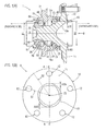
- FIG. 1(A) is an example of a cross-sectional view showing a wheel rolling bearing unit 1 according to the present invention, taken along the rotation axis ZS thereof
- FIG. 1(B) is an example of a front view showing the wheel rolling bearing unit 1.
- the view seen from the direction B in FIG. 1(A) is FIG. 1(B)
- the A-A cross-sectional view in FIG. 1(B) is FIG. 1(A)
- An inboard side is the inward side of a vehicle in the direction of the rotation axis ZS of the wheel rolling bearing
- an outboard side is the outward side of the vehicle in the direction of the rotation axis ZS.
- the wheel rolling bearing unit 1 (a so-called wheel hub unit) is equipped with a hub spindle 10 integrally having a shaft-shaped section 15 serving as an inner ring member constituting a double-row angular contact ball bearing and a flange section 11; an outer ring member 30; balls 50 on the inboard side row of the double rows; balls 51 on the outboard side row; a cage 55 for retaining the plurality of balls 50 at equal intervals; a cage 56 for retaining the plurality of balls 51 at equal intervals, these being formed into a unit.
- a hub spindle 10 integrally having a shaft-shaped section 15 serving as an inner ring member constituting a double-row angular contact ball bearing and a flange section 11; an outer ring member 30; balls 50 on the inboard side row of the double rows; balls 51 on the outboard side row; a cage 55 for retaining the plurality of balls 50 at equal intervals; a cage 56 for retaining the plurality of balls 51 at equal intervals, these being formed into
- a small-diameter section 17 and a large-diameter section 16 are formed into a stepped shaft shape from the inboard side of the rotation axis ZS, and a large-diameter shoulder section 16a having a larger diameter is formed on the outboard side of the large-diameter section 16. Furthermore, the flange section 11 is formed on the outboard side, one side of the shaft-shaped section 15 in the direction of the rotation axis ZS, and a spigot joint section 13 being extended in a cylindrical shape is formed on the outboard-side flange surface of the flange section 11.
- An inner ring element 26 is fitted on the outer peripheral surface of the small-diameter section 17 of the hub spindle 10, and the inboard-side end section of the hub spindle 10 is calked in the radial direction, whereby a calked section 18 is formed and the inner ring element 26 is integrally secured to the hub spindle 10. Furthermore, an inboard-side inner-ring raceway surface 20 is formed on the outer peripheral surface of the inner ring element 26 (the outer peripheral surface of the shaft-shaped section 15 of the hub spindle 10 being integrated). Moreover, an outboard-side inner-ring raceway surface 25 is formed on the outer peripheral surface of the large-diameter shoulder section 16a of the hub spindle 10 (the outer peripheral surface of the shaft-shaped section 15 of the hub spindle 10).
- the outer ring member 30 is disposed around the outer periphery of the shaft-shaped section 15, and on the inboard side of the outer ring member 30, a fitting shaft section 35 to be fitted into the mounting holes of vehicle body side members including a knuckle, a carrier or the like (not shown) supported by the suspension device of the vehicle is formed.
- a vehicle body flange section 31 that is secured with bolts or other means when the vehicle body side members are mounted thereon is formed (bolt holes or the like are not shown).
- an inboard-side outer-ring raceway surface 40 corresponding to the inboard-side inner-ring raceway surface 20 of the hub spindle 10 (the inner ring element 26) and an outboard-side outer-ring raceway surface 45 corresponding to the outboard-side inner-ring raceway surface 25 of the hub spindle 10 are formed with a predetermined distance provided therebetween in the direction of the rotation axis ZS.
- a plurality of balls 50 are arranged rotatably in a state of being retained in the cage 55.
- a plurality of balls 51 are arranged rotatably in a state of being retained in the cage 56. Furthermore, a required preload is applied respectively to the plurality of balls 50 and the plurality of balls 51 by the calking force exerted by the calked section 18 of the hub spindle 10.
- the pitch circle diameter D2 is set so as to be larger than the pitch circle diameter D1
- the diameter of the balls 51 on the outboard side row is set so as to be smaller than the diameter of the ball 50 on the inboard side row. Accordingly, the number of the balls 51 on the outboard side row is larger than the number of the balls 50 on the inboard side row.
- the hub spindle 10 integrally has the shaft-shaped section 15 having a nearly cylindrical shape and the flange section 11 formed on the outboard side of the shaft-shaped section 15 coaxially (with the shaft-shaped section 15) (coaxial with respect to the rotation axis ZS) and extended in the radial direction.
- a flange surface M1 (refer to FIG. 2 ) on the outboard side of the flange section 11, the spigot joint section 13 cylindrically extended to the outboard side is formed coaxially with the shaft-shaped section 15 and the flange section 11 so as to protrude.
- a plurality of hub bolts 12 for tightening a wheel are fixed at a predetermined pitch.
- the plurality of hub bolts 12 are provided in parallel with the direction of the rotation axis ZS.
- the center hole of a brake rotor BK and the center hole of a wheel WH are fitted around the spigot joint section 13 from the side of the flange surface M1 serving as the outboard-side surface of the flange section 11, and nuts NM are tightened onto the hub bolts 12, whereby the wheel WH is mounted on the wheel rolling bearing unit 1.
- a hollow concave section 10a is formed in a direction from the inner peripheral surface of the spigot joint section 13 toward the inboard side.
- the concave section 10a is formed deep so as to have a diameter as large as possible while a required thickness is left between the concave section and the outboard-side inner-ring raceway surface 25, whereby required rigidity is securely obtained and utmost possible weight reduction is attained. Since the center holes of the brake rotor BK and the wheel WH are fitted as described above and the center holes have been determined, the outside diameter of the spigot joint section 13 cannot be changed. Hence, the diameter of the concave section 10a (the inside diameter of the spigot joint section 13) is set so that a thickness capable of securely providing required rigidity for the spigot joint section 13 is obtained and so that a larger diameter is obtained to reduce weight.
- the spigot joint section 13 is made thinner uniformly or partially to realize further weight reduction without the thickness of the spigot joint section 13 not being made thicker, the spigot joint section can securely obtain rigidity equivalent to that of a spigot joint section having a conventional thickness.
- the surface roughness of an arc-shaped (in cross-section) boundary surface M2 at a boundary section where the outer peripheral surface M3 of the spigot joint section 13 is smoothly connected to the flange surface M1 is made finer (refer to FIG. 2 ).
- the surface roughness of the boundary surface M2 is made finer by turning or grinding.
- the thickness of the spigot joint section 13 can be made thinner uniformly while rigidity equivalent to or more than that of the conventional spigot joint section is securely obtained, and both weight reduction and securing of rigidity can be satisfied.
- the thickness at positions on the spigot joint section 13 not corresponding to the positions of the hub bolts 12 is made thinner partially.
- FIG. 1(B) it is assumed that the radial thickness of the spigot joint section 13 around the intersection point of a non-bolt position straight line S2 (refer to FIG. 1(B) ) serving as a straight line drawn in the radial direction from the rotation axis ZS toward each intermediate position between the hub bolts 12 adjacent to each other and the spigot joint section 13 is a non-bolt position thickness ⁇ D2.
- the radial thickness of the spigot joint section 13 around the intersection point of a bolt position straight line S1 (refer to FIG. 1(B) ) serving as a straight line drawn in the radial direction from the rotation axis ZS toward each hub bolt 12 and the spigot joint section 13 is a bolt position thickness ⁇ D1.
- a setting is made so that the relationship of non-bolt position thickness ⁇ D2 ⁇ bolt position thickness ⁇ D1 is obtained, whereby the required rigidity is securely obtained at the spigot joint section 13 and the thickness of the spigot joint section 13 is made thinner partially.
- This partially thinned shape can be formed relatively easily by using a punch that is made by hot forging or the like so as to have the inside diameter shape of the spigot joint section 13.
- the thickness of the spigot joint section 13 can be made thinner partially while rigidity equivalent to or more than that of the conventional spigot joint section is securely obtained, and both weight reduction and securing of rigidity can be satisfied.
- the optimal shape of the concave section 10a can be provided, the rigidity of the spigot joint section 13 can be suppressed from being lowered, and further weight reduction can be attained.
- the wheel rolling bearing unit 1 according to the present invention is not limited to have the external appearance, configuration, structure, shape or the like described in the embodiments, but various modifications, additions and deletions can be made without changing the gist of the present invention. Furthermore, both weight reduction and securing of rigidity can be satisfied by applying at least one of the wheel rolling bearing unit 1 described in the first embodiment and the wheel rolling bearing unit 1 described in the second embodiment. Moreover, the numerical values used in the description of the embodiments are examples and not limited thereto.
- both weight reduction and securing of rigidity can be satisfied in the spigot joint section formed so as to protrude from the flange surface on which a wheel is mounted.
Landscapes
- Engineering & Computer Science (AREA)
- Mechanical Engineering (AREA)
- General Engineering & Computer Science (AREA)
- Rolling Contact Bearings (AREA)
Abstract
To provide a rolling bearing device that is for a vehicle wheel and that is able to achieve both securing rigidity and lightness of weight of a faucet section that is formed in a manner so as to protrude from a flange surface that attaches the vehicle wheel. The present invention is provided with: a hub shaft (10) that has a flange section (11) and a shaft-shaped section (15) and to which an inner ring raceway is formed on the outside peripheral surface of the shaft-shaped section; an outer ring member (30) provided at the outer periphery of the shaft-shaped section and to which an outer ring raceway is formed on the inside peripheral surface; and a plurality of rolling elements provided between the inner ring raceway and the outer ring raceway. The flange section is formed to one side in the direction of the rotation axis (ZS), and a cylindrical faucet section (13) that protrudes to one side is formed at the flange surface coaxially to the hub shaft. The boundary section of the flange surface and the outer peripheral surface of the faucet section is formed from an arced boundary surface (M2) that is smoothly continuous from the outer peripheral surface (M3) of the faucet section (13) to the flange surface (M1), and the surface roughness of the boundary surface (M2) is finished to a finer surface roughness than the surface roughness of the flange surface (M1) and the surface roughness of the outer peripheral surface (M3) of the faucet section.
Description
- The present invention relates to a wheel rolling bearing unit to be used as a wheel bearing for vehicles or the like.
- Recent vehicles or the like are requested to be lighter in weight (improvement in fuel efficiency) to comply with CO2 emission regulations and also requested to be higher in rigidity to improve safety and mobility; hence, wheel rolling bearing units are also requested to be lighter in weight and higher in rigidity.
In a wheel rolling bearing unit to be used as a wheel bearing for vehicles or the like, the diameter thereof on the inboard side (the inward side of a vehicle) is determined to be relatively small in relation to suspension-related components (a knuckle, a carrier or the like) to which the bearing unit is connected (the diameter is determined so as to conform to the diameter depending on weight reduction or the like of the suspension-related components to which the bearing unit is connected). Furthermore, although the diameter of the bearing unit on the outboard side (the outward side of the vehicle) having a flange surface on which a wheel is mounted has a higher degree of design freedom than the diameter on the inboard side, if the diameter is made equal to or less than the diameter on the inboard side, required rigidity cannot be obtained securely in some cases.
For this reason, in the conventional art described inPatent Document 1, a rolling bearing unit in which the diameter on the outboard side is made larger than the diameter on the inboard side so as to securely obtain rigidity has been disclosed.
Furthermore, in the conventional art described inPatent Document 2, a wheel bearing unit in which the diameter on the outboard side is made larger than the diameter on the inboard side so as to securely obtain required rigidity and in which a proper bearing clearance range can be obtained securely has been disclosed.
Moreover, in the conventional art described in Patent Document 3, a wheel bearing unit in which the diameter on the outboard side is made larger than the diameter on the inboard side so as to securely obtain required rigidity and in which assembly work can be simplified has been disclosed. -
- Patent Document 1:
JP-A-2004-108449 - Patent Document 2:
JP-A-2008-089131 - Patent Document 3:
JP-A-2008-151247 - In all the bearing units described in
Patent Documents 1 to 3, the diameter on the outboard side is made larger than the diameter on the inboard side to improve rigidity, and a concave section is provided to attain weight reduction in the outboard-side central section of the flange surface on which a wheel is mounted. Furthermore, around the concave section, a spigot joint section cylindrically extended in the direction of the rotation axis is formed, and the outside diameter of the spigot joint section is made slightly smaller than the diameter of the hole formed at the central section of a wheel to be mounted.
Although the outside diameter of the cylindrical spigot joint section has been determined by requirements on the side of the wheel and cannot be changed, the inside diameter of the spigot joint section (the diameter of the concave section) can be changed appropriately. In the case that the inside diameter of the spigot joint section is made larger and the thickness of the cylindrical spigot joint section is made thinner, the weight can be reduced, but the rigidity necessary for the wheel to be mounted is lowered; on the other hand, in the case that the inside diameter of the spigot joint section is made smaller and the thickness thereof is made thicker, the rigidity is improved, but the weight increases.
In the conventional arts described inPatent Documents 1 to 3, nothing is described with respect to the spigot joint section satisfying both weight reduction and securing of rigidity. - The present invention is made in consideration of the these points, and it is an object of the present invention to provide a wheel rolling bearing unit capable of satisfying both weight reduction and securing of rigidity in a spigot joint section formed so as to protrude from a flange surface on which a wheel is mounted. Means for solving the Problem
- To solve the above-mentioned problem, a wheel rolling bearing unit according to the present invention takes the following measures.
First, a first aspect of the present invention provides a wheel rolling bearing unit comprises a hub spindle having a flange section on which a wheel to be is mounted and which is formed into a flange shape and a shaft-shaped section, an inner-ring raceway surface being formed on an outer peripheral surface of the shaft-shaped section, an outer ring member disposed around an outer periphery of the shaft-shaped section of the hub spindle, an outer-ring raceway surface being formed on an inner peripheral surface thereof corresponding to the inner-ring raceway surface, and a plurality of rolling elements disposed rotatably in an annular accommodation space formed between the inner-ring raceway surface and the outer-ring raceway surface.
The flange section is formed on one side in a direction of a rotation axis of the hub spindle, and on a flange surface which is a surface on one side of the flange section in the direction of the rotation axis, a cylindrical spigot joint section protruding on the one side is formed coaxially with the hub spindle.
Furthermore, a boundary section of the flange surface and an outer peripheral surface of the spigot joint section is formed so as to have an arc-shaped boundary surface where the outer peripheral surface of the spigot joint section is smoothly connected toward the flange surface, and finishing is performed so that a surface roughness of the boundary surface is finer than a surface roughness of the flange surface and a surface roughness of the outer peripheral surface of the spigot joint section. - According to this first aspect, reduction in fatigue strength due to reduction in surface texture on the boundary surface of the boundary section where the stress from the mounted wheel or the like is concentrated can be suppressed.
Hence, the thickness of the spigot joint section can be made thinner uniformly while rigidity equivalent to or more than that of the conventional spigot joint section is securely obtained, and both weight reduction and securing of rigidity can be satisfied. - Next, a second aspect of the present invention provides a wheel rolling bearing unit comprises a hub spindle having a flange section on which a wheel is to be mounted and which is formed into a flange shape and a shaft-shaped section, an inner-ring raceway surface being formed on an outer peripheral surface of the shaft-shaped section, an outer ring member disposed around an outer periphery of the shaft-shaped section of the hub spindle, an outer-ring raceway surface being formed on an inner peripheral surface thereof corresponding to the inner-ring raceway surface, and a plurality of rolling elements disposed rotatably in an annular accommodation space formed between the inner-ring raceway surface and the outer-ring raceway surface.
The flange section is formed on one side in a direction of a rotation axis of the hub spindle, on a flange surface which is a surface on one side of the flange section in the direction of the rotation axis, a cylindrical spigot joint section protruding on the one side is formed coaxially with the hub spindle, and a plurality of hub bolts for mounting the wheel is provided in the flange section in parallel with the direction of the rotation axis so as to surround the spigot joint section.
Furthermore, a non-bolt position thickness which id a thickness of the spigot joint section in a radial direction around an intersection point of a non-bolt position straight line which is a straight line drawn in the radial direction from the rotation axis of the hub spindle toward each intermediate position between hub bolts adjacent to each other and the spigot joint section is made thinner than a bolt position thickness which is a thickness of the spigot joint section in the radial direction around an intersection point of a bolt position straight line which is a straight line drawn in the radial direction from the rotation axis toward each hub bolt and the spigot joint section. - According to this second aspect, with respect to the thickness of the spigot joint section, the non-bolt position thickness is made thinner than the bolt position thickness.
Hence, the thickness of the spigot joint section can be made thinner partially while rigidity equivalent to or more than that of the conventional spigot joint section is securely obtained, and both weight reduction and securing of rigidity can be satisfied. -
-
FIGS. 1(A) and 1(B) are views illustrating examples showing a wheel rollingbearing unit 1 according to the present invention,FIG. 1(A) being a cross-sectional view, taken along the rotation axis ZS thereof, andFIG. 1(B) being a front view; and -
FIG. 2 is a view showing a state in which a wheel WH is mounted on the wheel rollingbearing unit 1 according to the present invention and an enlarged view showing a part of the spigotjoint section 13 thereof. - Modes for embodying the present invention will be described below using the drawings.
FIG. 1(A) is an example of a cross-sectional view showing a wheel rollingbearing unit 1 according to the present invention, taken along the rotation axis ZS thereof, andFIG. 1(B) is an example of a front view showing the wheel rollingbearing unit 1. The view seen from the direction B inFIG. 1(A) isFIG. 1(B) , and the A-A cross-sectional view inFIG. 1(B) isFIG. 1(A) .
An inboard side is the inward side of a vehicle in the direction of the rotation axis ZS of the wheel rolling bearing, and an outboard side is the outward side of the vehicle in the direction of the rotation axis ZS. - As shown in
FIG. 1(A) , the wheel rolling bearing unit 1 (a so-called wheel hub unit) is equipped with ahub spindle 10 integrally having a shaft-shaped section 15 serving as an inner ring member constituting a double-row angular contact ball bearing and aflange section 11; anouter ring member 30;balls 50 on the inboard side row of the double rows;balls 51 on the outboard side row; acage 55 for retaining the plurality ofballs 50 at equal intervals; acage 56 for retaining the plurality ofballs 51 at equal intervals, these being formed into a unit. - On the
hub spindle 10, a small-diameter section 17 and a large-diameter section 16 are formed into a stepped shaft shape from the inboard side of the rotation axis ZS, and a large-diameter shoulder section 16a having a larger diameter is formed on the outboard side of the large-diameter section 16.
Furthermore, theflange section 11 is formed on the outboard side, one side of the shaft-shaped section 15 in the direction of the rotation axis ZS, and aspigot joint section 13 being extended in a cylindrical shape is formed on the outboard-side flange surface of theflange section 11.
Aninner ring element 26 is fitted on the outer peripheral surface of the small-diameter section 17 of thehub spindle 10, and the inboard-side end section of thehub spindle 10 is calked in the radial direction, whereby a calkedsection 18 is formed and theinner ring element 26 is integrally secured to thehub spindle 10.
Furthermore, an inboard-side inner-ring raceway surface 20 is formed on the outer peripheral surface of the inner ring element 26 (the outer peripheral surface of the shaft-shaped section 15 of thehub spindle 10 being integrated).
Moreover, an outboard-side inner-ring raceway surface 25 is formed on the outer peripheral surface of the large-diameter shoulder section 16a of the hub spindle 10 (the outer peripheral surface of the shaft-shaped section 15 of the hub spindle 10). - The
outer ring member 30 is disposed around the outer periphery of the shaft-shapedsection 15, and on the inboard side of theouter ring member 30, afitting shaft section 35 to be fitted into the mounting holes of vehicle body side members including a knuckle, a carrier or the like (not shown) supported by the suspension device of the vehicle is formed.
In addition, on the outer peripheral surface of theouter ring member 30 adjacent to thefitting shaft section 35, a vehiclebody flange section 31 that is secured with bolts or other means when the vehicle body side members are mounted thereon is formed (bolt holes or the like are not shown).
Furthermore, on the inner peripheral surface of theouter ring member 30, an inboard-side outer-ring raceway surface 40 corresponding to the inboard-side inner-ring raceway surface 20 of the hub spindle 10 (the inner ring element 26) and an outboard-side outer-ring raceway surface 45 corresponding to the outboard-side inner-ring raceway surface 25 of thehub spindle 10 are formed with a predetermined distance provided therebetween in the direction of the rotation axis ZS. - In the accommodation space formed between the inboard-side inner-
ring raceway surface 20 and the inboard-side outer-ring raceway surface 40, a plurality ofballs 50 are arranged rotatably in a state of being retained in thecage 55. In addition, in the accommodation space formed between the outboard-side inner-ring raceway surface 25 and the outboard-side outer-ring raceway surface 45, a plurality ofballs 51 are arranged rotatably in a state of being retained in thecage 56.
Furthermore, a required preload is applied respectively to the plurality ofballs 50 and the plurality ofballs 51 by the calking force exerted by the calkedsection 18 of thehub spindle 10. - Moreover, in the wheel rolling bearing
unit 1 to be described in the embodiments of the present invention, as shown inFIGS. 1(A) and 1(B) , when it is assumed that the pitch circle diameter of the inboard-side balls 50 is D1 and that the pitch circle diameter of the outboard-side balls 51 is D2, a setting is made so that the relationship of pitch circle diameter D1 < pitch circle diameter D2 is obtained.
In other words, in order that the wheel rollingbearing unit 1 is made lighter in weight and higher in rigidity while the outside diameter dimension of thefitting shaft section 35 of theouter ring member 30 surely has a size insertable into the assembly holes of the vehicle body side members, the pitch circle diameter D2 is set so as to be larger than the pitch circle diameter D1, and the diameter of theballs 51 on the outboard side row is set so as to be smaller than the diameter of theball 50 on the inboard side row. Accordingly, the number of theballs 51 on the outboard side row is larger than the number of theballs 50 on the inboard side row. - The
hub spindle 10 integrally has the shaft-shaped section 15 having a nearly cylindrical shape and theflange section 11 formed on the outboard side of the shaft-shaped section 15 coaxially (with the shaft-shaped section 15) (coaxial with respect to the rotation axis ZS) and extended in the radial direction. In addition, on a flange surface M1 (refer toFIG. 2 ) on the outboard side of theflange section 11, thespigot joint section 13 cylindrically extended to the outboard side is formed coaxially with the shaft-shaped section 15 and theflange section 11 so as to protrude. Furthermore, at theflange section 11, a plurality ofhub bolts 12 for tightening a wheel are fixed at a predetermined pitch. Moreover, so as to surround the spigotjoint section 13, the plurality ofhub bolts 12 are provided in parallel with the direction of the rotation axis ZS.
What's more, as shown inFIG. 2 , the center hole of a brake rotor BK and the center hole of a wheel WH are fitted around thespigot joint section 13 from the side of the flange surface M1 serving as the outboard-side surface of theflange section 11, and nuts NM are tightened onto thehub bolts 12, whereby the wheel WH is mounted on the wheel rollingbearing unit 1. - Still further, a hollow
concave section 10a is formed in a direction from the inner peripheral surface of the spigotjoint section 13 toward the inboard side.
Theconcave section 10a is formed deep so as to have a diameter as large as possible while a required thickness is left between the concave section and the outboard-side inner-ring raceway surface 25, whereby required rigidity is securely obtained and utmost possible weight reduction is attained.
Since the center holes of the brake rotor BK and the wheel WH are fitted as described above and the center holes have been determined, the outside diameter of thespigot joint section 13 cannot be changed. Hence, the diameter of theconcave section 10a (the inside diameter of the spigot joint section 13) is set so that a thickness capable of securely providing required rigidity for thespigot joint section 13 is obtained and so that a larger diameter is obtained to reduce weight. - In the wheel rolling
bearing unit 1 according to the present invention, although the thickness of the spigotjoint section 13 is made thinner uniformly or partially to realize further weight reduction without the thickness of the spigotjoint section 13 not being made thicker, the spigot joint section can securely obtain rigidity equivalent to that of a spigot joint section having a conventional thickness. - In a first embodiment, the surface roughness of an arc-shaped (in cross-section) boundary surface M2 at a boundary section where the outer peripheral surface M3 of the spigot
joint section 13 is smoothly connected to the flange surface M1 is made finer (refer toFIG. 2 ).
As shown inFIG. 2 , since the stress from the brake rotor BK and the wheel WH is concentrated in the boundary surface M2 (round chamfered section) of the spigotjoint section 13, reduction in fatigue strength may occur. Hence, the surface roughness of the boundary surface M2 is made finer by turning or grinding. - For example, in the case of turning, the flange surface M1 and the outer peripheral surface M3 of the spigot
joint section 13 are machined so that an arithmetic average roughness of Ra = 6.3 [µm] is obtained; and in the case of machining the boundary surface M2, the machining is performed at a low feed rate so that Ra = 2.5 [µm] is obtained.
As a result, reduction in fatigue strength due to reduction in surface texture can be suppressed and reliability in strength can be improved further.
Hence, since the rigidity of the spigotjoint section 13 can be improved further, the thickness of the spigotjoint section 13 can be made thinner uniformly while rigidity equivalent to or more than that of the conventional spigot joint section is securely obtained, and both weight reduction and securing of rigidity can be satisfied. - In a second embodiment, while attention is paid to the fact that the brake rotor BK and the wheel WH are secured to the
flange section 11 of thehub spindle 10 using the plurality ofhub bolts 12, the thickness at positions on the spigotjoint section 13 not corresponding to the positions of thehub bolts 12 is made thinner partially.
As shown inFIG. 1(B) , it is assumed that the radial thickness of the spigotjoint section 13 around the intersection point of a non-bolt position straight line S2 (refer toFIG. 1(B) ) serving as a straight line drawn in the radial direction from the rotation axis ZS toward each intermediate position between thehub bolts 12 adjacent to each other and the spigotjoint section 13 is a non-bolt position thickness ΔD2.
In addition, it is assumed that the radial thickness of the spigotjoint section 13 around the intersection point of a bolt position straight line S1 (refer toFIG. 1(B) ) serving as a straight line drawn in the radial direction from the rotation axis ZS toward eachhub bolt 12 and the spigotjoint section 13 is a bolt position thickness ΔD1. - Furthermore, a setting is made so that the relationship of non-bolt position thickness ΔD2 < bolt position thickness ΔD1 is obtained, whereby the required rigidity is securely obtained at the spigot
joint section 13 and the thickness of the spigotjoint section 13 is made thinner partially. For example, a setting is made so that non-bolt position thickness ΔD2 : bolt position thickness ΔD1 = 1 : 1.1 is obtained.
This partially thinned shape can be formed relatively easily by using a punch that is made by hot forging or the like so as to have the inside diameter shape of the spigotjoint section 13.
Hence, the thickness of the spigotjoint section 13 can be made thinner partially while rigidity equivalent to or more than that of the conventional spigot joint section is securely obtained, and both weight reduction and securing of rigidity can be satisfied.
As described above, in the second embodiment, the optimal shape of theconcave section 10a can be provided, the rigidity of the spigotjoint section 13 can be suppressed from being lowered, and further weight reduction can be attained. - The wheel rolling
bearing unit 1 according to the present invention is not limited to have the external appearance, configuration, structure, shape or the like described in the embodiments, but various modifications, additions and deletions can be made without changing the gist of the present invention.
Furthermore, both weight reduction and securing of rigidity can be satisfied by applying at least one of the wheel rollingbearing unit 1 described in the first embodiment and the wheel rollingbearing unit 1 described in the second embodiment.
Moreover, the numerical values used in the description of the embodiments are examples and not limited thereto. - This application is based upon Japanese Patent Application No.
2011-007845 filed on January 18, 2011 - With the wheel rolling bearing unit according to the present invention, both weight reduction and securing of rigidity can be satisfied in the spigot joint section formed so as to protrude from the flange surface on which a wheel is mounted.
-
- 1
- wheel rolling bearing unit
- 10
- hub spindle
- 10a
- concave section
- 11
- flange section
- 12
- hub bolt
- 13
- spigot joint section
- 15
- shaft-shaped section
- 20, 25
- inner-ring raceway surface
- 30
- outer ring member
- 40, 45
- outer-ring raceway surface
- 50, 51
- ball
- 55, 56
- cage
- BK
- brake rotor
- M1
- flange surface
- M2
- boundary surface
- M3
- outer peripheral surface (of spigot joint section 13)
- S1
- bolt position straight line
- S2
- non-bolt position straight line
- WH
- wheel
- ZS
- rotation axis
- ΔD1
- bolt position thickness
- ΔD2
- non-bolt position thickness
Claims (2)
- A wheel rolling bearing unit comprising:a hub spindle having: a flange section on which a wheel is to be mounted and which is formed into a flange shape; and a shaft-shaped section, an inner-ring raceway surface being formed on an outer peripheral surface of the shaft-shaped section;an outer ring member disposed around an outer periphery of the shaft-shaped section of the hub spindle, an outer-ring raceway surface being formed on an inner peripheral surface thereof corresponding to the inner-ring raceway surface; anda plurality of rolling elements disposed rotatably in an annular accommodation space formed between the inner-ring raceway surface and the outer-ring raceway surface, whereinthe flange section is formed on one side in a direction of a rotation axis of the hub spindle,on a flange surface which is a surface on one side of the flange section in the direction of the rotation axis, a cylindrical spigot joint section protruding on the one side is formed coaxially with the hub spindle,a boundary section of the flange surface and an outer peripheral surface of the spigot joint section is formed so as to have an arc-shaped boundary surface where the outer peripheral surface of the spigot joint section is smoothly connected toward the flange surface, andfinishing is performed so that a surface roughness of the boundary surface is finer than a surface roughness of the flange surface and a surface roughness of the outer peripheral surface of the spigot joint section.
- A wheel rolling bearing unit comprising:a hub spindle having: a flange section on which a wheel is to be mounted and which is formed into a flange shape; and a shaft-shaped section, an inner-ring raceway surface being formed on an outer peripheral surface of the shaft-shaped section;an outer ring member disposed around an outer periphery of the shaft-shaped section of the hub spindle, an outer-ring raceway surface being formed on an inner peripheral surface thereof corresponding to the inner-ring raceway surface; anda plurality of rolling elements disposed rotatably in an annular accommodation space formed between the inner-ring raceway surface and the outer-ring raceway surface, whereinthe flange section is formed on one side in a direction of a rotation axis of the hub spindle,on a flange surface which is a surface on one side of the flange section in the direction of the rotation axis, a cylindrical spigot joint section protruding on the one side is formed coaxially with the hub spindle,a plurality of hub bolts for mounting the wheel is provided in the flange section in parallel with the direction of the rotation axis so as to surround the spigot joint section, anda non-bolt position thickness which is a thickness of the spigot joint section in a radial direction around an intersection point of a non-bolt position straight line which is a straight line drawn in the radial direction from the rotation axis of the hub spindle toward each intermediate position between hub bolts adjacent to each other and the spigot joint section is made thinner than a bolt position thickness which is a thickness of the spigot joint section in the radial direction around an intersection point of a bolt position straight line which is a straight line drawn in the radial direction from the rotation axis toward each hub bolt and the spigot joint section.
Applications Claiming Priority (2)
| Application Number | Priority Date | Filing Date | Title |
|---|---|---|---|
| JP2011007845A JP2012148643A (en) | 2011-01-18 | 2011-01-18 | Rolling bearing device for wheel |
| PCT/JP2012/050761 WO2012099081A1 (en) | 2011-01-18 | 2012-01-17 | Rolling bearing device for vehicle wheel |
Publications (1)
| Publication Number | Publication Date |
|---|---|
| EP2666647A1 true EP2666647A1 (en) | 2013-11-27 |
Family
ID=46515706
Family Applications (1)
| Application Number | Title | Priority Date | Filing Date |
|---|---|---|---|
| EP12736303.4A Withdrawn EP2666647A1 (en) | 2011-01-18 | 2012-01-17 | Rolling bearing device for vehicle wheel |
Country Status (5)
| Country | Link |
|---|---|
| US (1) | US20130292996A1 (en) |
| EP (1) | EP2666647A1 (en) |
| JP (1) | JP2012148643A (en) |
| CN (1) | CN103328229A (en) |
| WO (1) | WO2012099081A1 (en) |
Families Citing this family (7)
| Publication number | Priority date | Publication date | Assignee | Title |
|---|---|---|---|---|
| JP6604484B2 (en) | 2017-03-07 | 2019-11-13 | トヨタ自動車株式会社 | Wheel mounting structure |
| JP6845475B2 (en) | 2017-04-18 | 2021-03-17 | トヨタ自動車株式会社 | Wheel mounting structure |
| KR102556456B1 (en) * | 2018-04-27 | 2023-07-18 | 주식회사 일진글로벌 | wheel bearing assembly |
| KR20190125108A (en) * | 2018-04-27 | 2019-11-06 | 주식회사 일진글로벌 | Wheel bearing assembly |
| US11731456B2 (en) * | 2019-05-24 | 2023-08-22 | Aktiebolaget Skf | Wheel hub bearing with radial stiffening |
| CN112664565A (en) * | 2020-12-24 | 2021-04-16 | 浙江万向精工有限公司 | Hub bearing unit for laser material increase and processing method |
| CN115949669B (en) * | 2022-12-30 | 2024-01-12 | 北京艾比特动力技术有限公司 | Spring plate locking bearing |
Family Cites Families (13)
| Publication number | Priority date | Publication date | Assignee | Title |
|---|---|---|---|---|
| US4368554A (en) * | 1980-03-28 | 1983-01-18 | Hestair Eagle Limited | Road sweeping apparatus |
| JP4206716B2 (en) | 2002-09-17 | 2009-01-14 | 株式会社ジェイテクト | Rolling bearing device |
| JP2005231601A (en) * | 2004-02-23 | 2005-09-02 | Koyo Seiko Co Ltd | Rolling bearing device |
| JP2005349928A (en) * | 2004-06-10 | 2005-12-22 | Ntn Corp | Bearing device for wheel |
| JP4772637B2 (en) | 2006-10-04 | 2011-09-14 | Ntn株式会社 | Wheel bearing device |
| JP4883693B2 (en) | 2006-12-18 | 2012-02-22 | Ntn株式会社 | Assembly method for wheel bearing device |
| JP5031460B2 (en) * | 2007-06-28 | 2012-09-19 | Ntn株式会社 | Wheel bearing device |
| JP5184875B2 (en) * | 2007-12-19 | 2013-04-17 | Ntn株式会社 | Wheel bearing device |
| JP2009156450A (en) * | 2007-12-28 | 2009-07-16 | Ntn Corp | Bearing device for wheel |
| JP2009191907A (en) * | 2008-02-13 | 2009-08-27 | Ntn Corp | Wheel bearing device |
| JP2009191902A (en) * | 2008-02-13 | 2009-08-27 | Ntn Corp | Wheel bearing device |
| JP2010188834A (en) * | 2009-02-17 | 2010-09-02 | Jtekt Corp | Wheel bearing device |
| CN101804770B (en) * | 2009-02-17 | 2015-03-04 | 株式会社捷太格特 | Wheel bearing device and manufacturing method therefor |
-
2011
- 2011-01-18 JP JP2011007845A patent/JP2012148643A/en active Pending
-
2012
- 2012-01-17 EP EP12736303.4A patent/EP2666647A1/en not_active Withdrawn
- 2012-01-17 CN CN2012800057884A patent/CN103328229A/en active Pending
- 2012-01-17 US US13/979,280 patent/US20130292996A1/en not_active Abandoned
- 2012-01-17 WO PCT/JP2012/050761 patent/WO2012099081A1/en not_active Ceased
Non-Patent Citations (1)
| Title |
|---|
| See references of WO2012099081A1 * |
Also Published As
| Publication number | Publication date |
|---|---|
| US20130292996A1 (en) | 2013-11-07 |
| WO2012099081A1 (en) | 2012-07-26 |
| JP2012148643A (en) | 2012-08-09 |
| CN103328229A (en) | 2013-09-25 |
Similar Documents
| Publication | Publication Date | Title |
|---|---|---|
| US20130292996A1 (en) | Wheel rolling bearing unit | |
| US8616779B2 (en) | Shortened driveshaft stem | |
| US9259962B2 (en) | Integrated hub-bearing assembly for the wheel of a motor vehicle | |
| CN107405951B (en) | Wheel bearing device | |
| US8915651B2 (en) | Wheel rolling bearing device | |
| US9573419B2 (en) | Wheel bearing apparatus and its manufacturing method | |
| CN102602245B (en) | Bearing unit for wheel | |
| US20150191044A1 (en) | Bearing module | |
| JP5549386B2 (en) | Wheel bearing device | |
| JP6366233B2 (en) | Wheel bearing device | |
| JP6007655B2 (en) | Wheel bearing device | |
| JP2011207298A (en) | Inner ring of bearing device for wheel | |
| JP2008173995A (en) | Bearing device for wheel | |
| JP2017065296A (en) | Bearing device for wheel | |
| EP2042345B1 (en) | Rolling bearing unit for wheel | |
| EP1800898B1 (en) | Hub unit for vehicle | |
| US20130301968A1 (en) | Hub spindle bearing unit for wheel | |
| JP6054124B2 (en) | Wheel bearing device | |
| JP5236097B2 (en) | Wheel bearing device | |
| JP2008051165A (en) | Bearing device for wheel | |
| JP4034799B2 (en) | Wheel bearing device | |
| JP2006273254A (en) | Rolling bearing device for wheels | |
| JP2007307934A (en) | Bearing device for wheel | |
| JP2007276739A (en) | Drive wheel hub unit | |
| JP2015001295A (en) | Wheel bearing device |
Legal Events
| Date | Code | Title | Description |
|---|---|---|---|
| PUAI | Public reference made under article 153(3) epc to a published international application that has entered the european phase |
Free format text: ORIGINAL CODE: 0009012 |
|
| 17P | Request for examination filed |
Effective date: 20130717 |
|
| AK | Designated contracting states |
Kind code of ref document: A1 Designated state(s): AL AT BE BG CH CY CZ DE DK EE ES FI FR GB GR HR HU IE IS IT LI LT LU LV MC MK MT NL NO PL PT RO RS SE SI SK SM TR |
|
| DAX | Request for extension of the european patent (deleted) | ||
| STAA | Information on the status of an ep patent application or granted ep patent |
Free format text: STATUS: THE APPLICATION HAS BEEN WITHDRAWN |
|
| 18W | Application withdrawn |
Effective date: 20141013 |