EP2666582A1 - Braze compositions, and related devices - Google Patents
Braze compositions, and related devices Download PDFInfo
- Publication number
- EP2666582A1 EP2666582A1 EP13169250.1A EP13169250A EP2666582A1 EP 2666582 A1 EP2666582 A1 EP 2666582A1 EP 13169250 A EP13169250 A EP 13169250A EP 2666582 A1 EP2666582 A1 EP 2666582A1
- Authority
- EP
- European Patent Office
- Prior art keywords
- weight percent
- braze alloy
- braze
- alloy composition
- alloy
- Prior art date
- Legal status (The legal status is an assumption and is not a legal conclusion. Google has not performed a legal analysis and makes no representation as to the accuracy of the status listed.)
- Granted
Links
Images

Classifications
-
- B—PERFORMING OPERATIONS; TRANSPORTING
- B23—MACHINE TOOLS; METAL-WORKING NOT OTHERWISE PROVIDED FOR
- B23K—SOLDERING OR UNSOLDERING; WELDING; CLADDING OR PLATING BY SOLDERING OR WELDING; CUTTING BY APPLYING HEAT LOCALLY, e.g. FLAME CUTTING; WORKING BY LASER BEAM
- B23K35/00—Rods, electrodes, materials, or media, for use in soldering, welding, or cutting
- B23K35/22—Rods, electrodes, materials, or media, for use in soldering, welding, or cutting characterised by the composition or nature of the material
- B23K35/24—Selection of soldering or welding materials proper
- B23K35/30—Selection of soldering or welding materials proper with the principal constituent melting at less than 1550°C
- B23K35/3033—Ni as the principal constituent
- B23K35/304—Ni as the principal constituent with Cr as the next major constituent
-
- B—PERFORMING OPERATIONS; TRANSPORTING
- B23—MACHINE TOOLS; METAL-WORKING NOT OTHERWISE PROVIDED FOR
- B23K—SOLDERING OR UNSOLDERING; WELDING; CLADDING OR PLATING BY SOLDERING OR WELDING; CUTTING BY APPLYING HEAT LOCALLY, e.g. FLAME CUTTING; WORKING BY LASER BEAM
- B23K35/00—Rods, electrodes, materials, or media, for use in soldering, welding, or cutting
- B23K35/22—Rods, electrodes, materials, or media, for use in soldering, welding, or cutting characterised by the composition or nature of the material
- B23K35/24—Selection of soldering or welding materials proper
- B23K35/30—Selection of soldering or welding materials proper with the principal constituent melting at less than 1550°C
-
- B—PERFORMING OPERATIONS; TRANSPORTING
- B23—MACHINE TOOLS; METAL-WORKING NOT OTHERWISE PROVIDED FOR
- B23K—SOLDERING OR UNSOLDERING; WELDING; CLADDING OR PLATING BY SOLDERING OR WELDING; CUTTING BY APPLYING HEAT LOCALLY, e.g. FLAME CUTTING; WORKING BY LASER BEAM
- B23K35/00—Rods, electrodes, materials, or media, for use in soldering, welding, or cutting
- B23K35/001—Interlayers, transition pieces for metallurgical bonding of workpieces
-
- B—PERFORMING OPERATIONS; TRANSPORTING
- B23—MACHINE TOOLS; METAL-WORKING NOT OTHERWISE PROVIDED FOR
- B23K—SOLDERING OR UNSOLDERING; WELDING; CLADDING OR PLATING BY SOLDERING OR WELDING; CUTTING BY APPLYING HEAT LOCALLY, e.g. FLAME CUTTING; WORKING BY LASER BEAM
- B23K35/00—Rods, electrodes, materials, or media, for use in soldering, welding, or cutting
- B23K35/001—Interlayers, transition pieces for metallurgical bonding of workpieces
- B23K35/004—Interlayers, transition pieces for metallurgical bonding of workpieces at least one of the workpieces being of a metal of the iron group
-
- B—PERFORMING OPERATIONS; TRANSPORTING
- B23—MACHINE TOOLS; METAL-WORKING NOT OTHERWISE PROVIDED FOR
- B23K—SOLDERING OR UNSOLDERING; WELDING; CLADDING OR PLATING BY SOLDERING OR WELDING; CUTTING BY APPLYING HEAT LOCALLY, e.g. FLAME CUTTING; WORKING BY LASER BEAM
- B23K35/00—Rods, electrodes, materials, or media, for use in soldering, welding, or cutting
- B23K35/02—Rods, electrodes, materials, or media, for use in soldering, welding, or cutting characterised by mechanical features, e.g. shape
- B23K35/0222—Rods, electrodes, materials, or media, for use in soldering, welding, or cutting characterised by mechanical features, e.g. shape for use in soldering or brazing
- B23K35/0233—Sheets or foils
-
- B—PERFORMING OPERATIONS; TRANSPORTING
- B23—MACHINE TOOLS; METAL-WORKING NOT OTHERWISE PROVIDED FOR
- B23K—SOLDERING OR UNSOLDERING; WELDING; CLADDING OR PLATING BY SOLDERING OR WELDING; CUTTING BY APPLYING HEAT LOCALLY, e.g. FLAME CUTTING; WORKING BY LASER BEAM
- B23K35/00—Rods, electrodes, materials, or media, for use in soldering, welding, or cutting
- B23K35/02—Rods, electrodes, materials, or media, for use in soldering, welding, or cutting characterised by mechanical features, e.g. shape
- B23K35/0222—Rods, electrodes, materials, or media, for use in soldering, welding, or cutting characterised by mechanical features, e.g. shape for use in soldering or brazing
- B23K35/0233—Sheets or foils
- B23K35/0238—Sheets or foils layered
-
- B—PERFORMING OPERATIONS; TRANSPORTING
- B23—MACHINE TOOLS; METAL-WORKING NOT OTHERWISE PROVIDED FOR
- B23K—SOLDERING OR UNSOLDERING; WELDING; CLADDING OR PLATING BY SOLDERING OR WELDING; CUTTING BY APPLYING HEAT LOCALLY, e.g. FLAME CUTTING; WORKING BY LASER BEAM
- B23K35/00—Rods, electrodes, materials, or media, for use in soldering, welding, or cutting
- B23K35/22—Rods, electrodes, materials, or media, for use in soldering, welding, or cutting characterised by the composition or nature of the material
- B23K35/24—Selection of soldering or welding materials proper
- B23K35/30—Selection of soldering or welding materials proper with the principal constituent melting at less than 1550°C
- B23K35/3033—Ni as the principal constituent
-
- B—PERFORMING OPERATIONS; TRANSPORTING
- B23—MACHINE TOOLS; METAL-WORKING NOT OTHERWISE PROVIDED FOR
- B23K—SOLDERING OR UNSOLDERING; WELDING; CLADDING OR PLATING BY SOLDERING OR WELDING; CUTTING BY APPLYING HEAT LOCALLY, e.g. FLAME CUTTING; WORKING BY LASER BEAM
- B23K35/00—Rods, electrodes, materials, or media, for use in soldering, welding, or cutting
- B23K35/22—Rods, electrodes, materials, or media, for use in soldering, welding, or cutting characterised by the composition or nature of the material
- B23K35/24—Selection of soldering or welding materials proper
- B23K35/32—Selection of soldering or welding materials proper with the principal constituent melting at more than 1550°C
- B23K35/327—Selection of soldering or welding materials proper with the principal constituent melting at more than 1550°C comprising refractory compounds, e.g. carbides
-
- C—CHEMISTRY; METALLURGY
- C04—CEMENTS; CONCRETE; ARTIFICIAL STONE; CERAMICS; REFRACTORIES
- C04B—LIME, MAGNESIA; SLAG; CEMENTS; COMPOSITIONS THEREOF, e.g. MORTARS, CONCRETE OR LIKE BUILDING MATERIALS; ARTIFICIAL STONE; CERAMICS; REFRACTORIES; TREATMENT OF NATURAL STONE
- C04B37/00—Joining burned ceramic articles with other burned ceramic articles or other articles by heating
- C04B37/003—Joining burned ceramic articles with other burned ceramic articles or other articles by heating by means of an interlayer consisting of a combination of materials selected from glass, or ceramic material with metals, metal oxides or metal salts
- C04B37/006—Joining burned ceramic articles with other burned ceramic articles or other articles by heating by means of an interlayer consisting of a combination of materials selected from glass, or ceramic material with metals, metal oxides or metal salts consisting of metals or metal salts
-
- C—CHEMISTRY; METALLURGY
- C04—CEMENTS; CONCRETE; ARTIFICIAL STONE; CERAMICS; REFRACTORIES
- C04B—LIME, MAGNESIA; SLAG; CEMENTS; COMPOSITIONS THEREOF, e.g. MORTARS, CONCRETE OR LIKE BUILDING MATERIALS; ARTIFICIAL STONE; CERAMICS; REFRACTORIES; TREATMENT OF NATURAL STONE
- C04B37/00—Joining burned ceramic articles with other burned ceramic articles or other articles by heating
- C04B37/02—Joining burned ceramic articles with other burned ceramic articles or other articles by heating with metallic articles
- C04B37/023—Joining burned ceramic articles with other burned ceramic articles or other articles by heating with metallic articles characterised by the interlayer used
- C04B37/026—Joining burned ceramic articles with other burned ceramic articles or other articles by heating with metallic articles characterised by the interlayer used consisting of metals or metal salts
-
- C—CHEMISTRY; METALLURGY
- C22—METALLURGY; FERROUS OR NON-FERROUS ALLOYS; TREATMENT OF ALLOYS OR NON-FERROUS METALS
- C22C—ALLOYS
- C22C19/00—Alloys based on nickel or cobalt
- C22C19/03—Alloys based on nickel or cobalt based on nickel
- C22C19/05—Alloys based on nickel or cobalt based on nickel with chromium
-
- C—CHEMISTRY; METALLURGY
- C22—METALLURGY; FERROUS OR NON-FERROUS ALLOYS; TREATMENT OF ALLOYS OR NON-FERROUS METALS
- C22C—ALLOYS
- C22C9/00—Alloys based on copper
- C22C9/06—Alloys based on copper with nickel or cobalt as the next major constituent
-
- H—ELECTRICITY
- H01—ELECTRIC ELEMENTS
- H01M—PROCESSES OR MEANS, e.g. BATTERIES, FOR THE DIRECT CONVERSION OF CHEMICAL ENERGY INTO ELECTRICAL ENERGY
- H01M10/00—Secondary cells; Manufacture thereof
- H01M10/02—Details
-
- H—ELECTRICITY
- H01—ELECTRIC ELEMENTS
- H01M—PROCESSES OR MEANS, e.g. BATTERIES, FOR THE DIRECT CONVERSION OF CHEMICAL ENERGY INTO ELECTRICAL ENERGY
- H01M10/00—Secondary cells; Manufacture thereof
- H01M10/36—Accumulators not provided for in groups H01M10/05-H01M10/34
- H01M10/39—Accumulators not provided for in groups H01M10/05-H01M10/34 working at high temperature
-
- H—ELECTRICITY
- H01—ELECTRIC ELEMENTS
- H01M—PROCESSES OR MEANS, e.g. BATTERIES, FOR THE DIRECT CONVERSION OF CHEMICAL ENERGY INTO ELECTRICAL ENERGY
- H01M10/00—Secondary cells; Manufacture thereof
- H01M10/36—Accumulators not provided for in groups H01M10/05-H01M10/34
- H01M10/39—Accumulators not provided for in groups H01M10/05-H01M10/34 working at high temperature
- H01M10/3909—Sodium-sulfur cells
- H01M10/3963—Sealing means between the solid electrolyte and holders
-
- H—ELECTRICITY
- H01—ELECTRIC ELEMENTS
- H01M—PROCESSES OR MEANS, e.g. BATTERIES, FOR THE DIRECT CONVERSION OF CHEMICAL ENERGY INTO ELECTRICAL ENERGY
- H01M4/00—Electrodes
- H01M4/02—Electrodes composed of, or comprising, active material
-
- H—ELECTRICITY
- H01—ELECTRIC ELEMENTS
- H01M—PROCESSES OR MEANS, e.g. BATTERIES, FOR THE DIRECT CONVERSION OF CHEMICAL ENERGY INTO ELECTRICAL ENERGY
- H01M50/00—Constructional details or processes of manufacture of the non-active parts of electrochemical cells other than fuel cells, e.g. hybrid cells
- H01M50/10—Primary casings; Jackets or wrappings
- H01M50/183—Sealing members
- H01M50/186—Sealing members characterised by the disposition of the sealing members
-
- H—ELECTRICITY
- H01—ELECTRIC ELEMENTS
- H01M—PROCESSES OR MEANS, e.g. BATTERIES, FOR THE DIRECT CONVERSION OF CHEMICAL ENERGY INTO ELECTRICAL ENERGY
- H01M50/00—Constructional details or processes of manufacture of the non-active parts of electrochemical cells other than fuel cells, e.g. hybrid cells
- H01M50/10—Primary casings; Jackets or wrappings
- H01M50/183—Sealing members
- H01M50/19—Sealing members characterised by the material
- H01M50/191—Inorganic material
-
- H—ELECTRICITY
- H01—ELECTRIC ELEMENTS
- H01M—PROCESSES OR MEANS, e.g. BATTERIES, FOR THE DIRECT CONVERSION OF CHEMICAL ENERGY INTO ELECTRICAL ENERGY
- H01M6/00—Primary cells; Manufacture thereof
-
- B—PERFORMING OPERATIONS; TRANSPORTING
- B23—MACHINE TOOLS; METAL-WORKING NOT OTHERWISE PROVIDED FOR
- B23K—SOLDERING OR UNSOLDERING; WELDING; CLADDING OR PLATING BY SOLDERING OR WELDING; CUTTING BY APPLYING HEAT LOCALLY, e.g. FLAME CUTTING; WORKING BY LASER BEAM
- B23K2101/00—Articles made by soldering, welding or cutting
- B23K2101/18—Sheet panels
-
- B—PERFORMING OPERATIONS; TRANSPORTING
- B23—MACHINE TOOLS; METAL-WORKING NOT OTHERWISE PROVIDED FOR
- B23K—SOLDERING OR UNSOLDERING; WELDING; CLADDING OR PLATING BY SOLDERING OR WELDING; CUTTING BY APPLYING HEAT LOCALLY, e.g. FLAME CUTTING; WORKING BY LASER BEAM
- B23K2101/00—Articles made by soldering, welding or cutting
- B23K2101/36—Electric or electronic devices
-
- B—PERFORMING OPERATIONS; TRANSPORTING
- B23—MACHINE TOOLS; METAL-WORKING NOT OTHERWISE PROVIDED FOR
- B23K—SOLDERING OR UNSOLDERING; WELDING; CLADDING OR PLATING BY SOLDERING OR WELDING; CUTTING BY APPLYING HEAT LOCALLY, e.g. FLAME CUTTING; WORKING BY LASER BEAM
- B23K2101/00—Articles made by soldering, welding or cutting
- B23K2101/36—Electric or electronic devices
- B23K2101/38—Conductors
-
- B—PERFORMING OPERATIONS; TRANSPORTING
- B23—MACHINE TOOLS; METAL-WORKING NOT OTHERWISE PROVIDED FOR
- B23K—SOLDERING OR UNSOLDERING; WELDING; CLADDING OR PLATING BY SOLDERING OR WELDING; CUTTING BY APPLYING HEAT LOCALLY, e.g. FLAME CUTTING; WORKING BY LASER BEAM
- B23K2103/00—Materials to be soldered, welded or cut
- B23K2103/16—Composite materials
-
- B—PERFORMING OPERATIONS; TRANSPORTING
- B23—MACHINE TOOLS; METAL-WORKING NOT OTHERWISE PROVIDED FOR
- B23K—SOLDERING OR UNSOLDERING; WELDING; CLADDING OR PLATING BY SOLDERING OR WELDING; CUTTING BY APPLYING HEAT LOCALLY, e.g. FLAME CUTTING; WORKING BY LASER BEAM
- B23K2103/00—Materials to be soldered, welded or cut
- B23K2103/18—Dissimilar materials
-
- B—PERFORMING OPERATIONS; TRANSPORTING
- B23—MACHINE TOOLS; METAL-WORKING NOT OTHERWISE PROVIDED FOR
- B23K—SOLDERING OR UNSOLDERING; WELDING; CLADDING OR PLATING BY SOLDERING OR WELDING; CUTTING BY APPLYING HEAT LOCALLY, e.g. FLAME CUTTING; WORKING BY LASER BEAM
- B23K2103/00—Materials to be soldered, welded or cut
- B23K2103/18—Dissimilar materials
- B23K2103/26—Alloys of Nickel and Cobalt and Chromium
-
- B—PERFORMING OPERATIONS; TRANSPORTING
- B23—MACHINE TOOLS; METAL-WORKING NOT OTHERWISE PROVIDED FOR
- B23K—SOLDERING OR UNSOLDERING; WELDING; CLADDING OR PLATING BY SOLDERING OR WELDING; CUTTING BY APPLYING HEAT LOCALLY, e.g. FLAME CUTTING; WORKING BY LASER BEAM
- B23K2103/00—Materials to be soldered, welded or cut
- B23K2103/50—Inorganic materials other than metals or composite materials
- B23K2103/52—Ceramics
-
- B—PERFORMING OPERATIONS; TRANSPORTING
- B23—MACHINE TOOLS; METAL-WORKING NOT OTHERWISE PROVIDED FOR
- B23K—SOLDERING OR UNSOLDERING; WELDING; CLADDING OR PLATING BY SOLDERING OR WELDING; CUTTING BY APPLYING HEAT LOCALLY, e.g. FLAME CUTTING; WORKING BY LASER BEAM
- B23K35/00—Rods, electrodes, materials, or media, for use in soldering, welding, or cutting
- B23K35/02—Rods, electrodes, materials, or media, for use in soldering, welding, or cutting characterised by mechanical features, e.g. shape
- B23K35/0222—Rods, electrodes, materials, or media, for use in soldering, welding, or cutting characterised by mechanical features, e.g. shape for use in soldering or brazing
- B23K35/0244—Powders, particles or spheres; Preforms made therefrom
-
- B—PERFORMING OPERATIONS; TRANSPORTING
- B23—MACHINE TOOLS; METAL-WORKING NOT OTHERWISE PROVIDED FOR
- B23K—SOLDERING OR UNSOLDERING; WELDING; CLADDING OR PLATING BY SOLDERING OR WELDING; CUTTING BY APPLYING HEAT LOCALLY, e.g. FLAME CUTTING; WORKING BY LASER BEAM
- B23K35/00—Rods, electrodes, materials, or media, for use in soldering, welding, or cutting
- B23K35/02—Rods, electrodes, materials, or media, for use in soldering, welding, or cutting characterised by mechanical features, e.g. shape
- B23K35/0222—Rods, electrodes, materials, or media, for use in soldering, welding, or cutting characterised by mechanical features, e.g. shape for use in soldering or brazing
- B23K35/0244—Powders, particles or spheres; Preforms made therefrom
- B23K35/025—Pastes, creams or slurries
-
- C—CHEMISTRY; METALLURGY
- C04—CEMENTS; CONCRETE; ARTIFICIAL STONE; CERAMICS; REFRACTORIES
- C04B—LIME, MAGNESIA; SLAG; CEMENTS; COMPOSITIONS THEREOF, e.g. MORTARS, CONCRETE OR LIKE BUILDING MATERIALS; ARTIFICIAL STONE; CERAMICS; REFRACTORIES; TREATMENT OF NATURAL STONE
- C04B2237/00—Aspects relating to ceramic laminates or to joining of ceramic articles with other articles by heating
- C04B2237/02—Aspects relating to interlayers, e.g. used to join ceramic articles with other articles by heating
- C04B2237/12—Metallic interlayers
- C04B2237/123—Metallic interlayers based on iron group metals, e.g. steel
-
- C—CHEMISTRY; METALLURGY
- C04—CEMENTS; CONCRETE; ARTIFICIAL STONE; CERAMICS; REFRACTORIES
- C04B—LIME, MAGNESIA; SLAG; CEMENTS; COMPOSITIONS THEREOF, e.g. MORTARS, CONCRETE OR LIKE BUILDING MATERIALS; ARTIFICIAL STONE; CERAMICS; REFRACTORIES; TREATMENT OF NATURAL STONE
- C04B2237/00—Aspects relating to ceramic laminates or to joining of ceramic articles with other articles by heating
- C04B2237/02—Aspects relating to interlayers, e.g. used to join ceramic articles with other articles by heating
- C04B2237/12—Metallic interlayers
- C04B2237/124—Metallic interlayers based on copper
-
- C—CHEMISTRY; METALLURGY
- C04—CEMENTS; CONCRETE; ARTIFICIAL STONE; CERAMICS; REFRACTORIES
- C04B—LIME, MAGNESIA; SLAG; CEMENTS; COMPOSITIONS THEREOF, e.g. MORTARS, CONCRETE OR LIKE BUILDING MATERIALS; ARTIFICIAL STONE; CERAMICS; REFRACTORIES; TREATMENT OF NATURAL STONE
- C04B2237/00—Aspects relating to ceramic laminates or to joining of ceramic articles with other articles by heating
- C04B2237/02—Aspects relating to interlayers, e.g. used to join ceramic articles with other articles by heating
- C04B2237/12—Metallic interlayers
- C04B2237/126—Metallic interlayers wherein the active component for bonding is not the largest fraction of the interlayer
- C04B2237/127—The active component for bonding being a refractory metal
-
- C—CHEMISTRY; METALLURGY
- C04—CEMENTS; CONCRETE; ARTIFICIAL STONE; CERAMICS; REFRACTORIES
- C04B—LIME, MAGNESIA; SLAG; CEMENTS; COMPOSITIONS THEREOF, e.g. MORTARS, CONCRETE OR LIKE BUILDING MATERIALS; ARTIFICIAL STONE; CERAMICS; REFRACTORIES; TREATMENT OF NATURAL STONE
- C04B2237/00—Aspects relating to ceramic laminates or to joining of ceramic articles with other articles by heating
- C04B2237/30—Composition of layers of ceramic laminates or of ceramic or metallic articles to be joined by heating, e.g. Si substrates
- C04B2237/32—Ceramic
- C04B2237/34—Oxidic
- C04B2237/343—Alumina or aluminates
-
- C—CHEMISTRY; METALLURGY
- C04—CEMENTS; CONCRETE; ARTIFICIAL STONE; CERAMICS; REFRACTORIES
- C04B—LIME, MAGNESIA; SLAG; CEMENTS; COMPOSITIONS THEREOF, e.g. MORTARS, CONCRETE OR LIKE BUILDING MATERIALS; ARTIFICIAL STONE; CERAMICS; REFRACTORIES; TREATMENT OF NATURAL STONE
- C04B2237/00—Aspects relating to ceramic laminates or to joining of ceramic articles with other articles by heating
- C04B2237/30—Composition of layers of ceramic laminates or of ceramic or metallic articles to be joined by heating, e.g. Si substrates
- C04B2237/40—Metallic
- C04B2237/405—Iron metal group, e.g. Co or Ni
-
- C—CHEMISTRY; METALLURGY
- C04—CEMENTS; CONCRETE; ARTIFICIAL STONE; CERAMICS; REFRACTORIES
- C04B—LIME, MAGNESIA; SLAG; CEMENTS; COMPOSITIONS THEREOF, e.g. MORTARS, CONCRETE OR LIKE BUILDING MATERIALS; ARTIFICIAL STONE; CERAMICS; REFRACTORIES; TREATMENT OF NATURAL STONE
- C04B2237/00—Aspects relating to ceramic laminates or to joining of ceramic articles with other articles by heating
- C04B2237/50—Processing aspects relating to ceramic laminates or to the joining of ceramic articles with other articles by heating
- C04B2237/70—Forming laminates or joined articles comprising layers of a specific, unusual thickness
-
- H—ELECTRICITY
- H01—ELECTRIC ELEMENTS
- H01M—PROCESSES OR MEANS, e.g. BATTERIES, FOR THE DIRECT CONVERSION OF CHEMICAL ENERGY INTO ELECTRICAL ENERGY
- H01M10/00—Secondary cells; Manufacture thereof
- H01M10/36—Accumulators not provided for in groups H01M10/05-H01M10/34
- H01M10/38—Construction or manufacture
-
- H—ELECTRICITY
- H01—ELECTRIC ELEMENTS
- H01M—PROCESSES OR MEANS, e.g. BATTERIES, FOR THE DIRECT CONVERSION OF CHEMICAL ENERGY INTO ELECTRICAL ENERGY
- H01M50/00—Constructional details or processes of manufacture of the non-active parts of electrochemical cells other than fuel cells, e.g. hybrid cells
- H01M50/10—Primary casings; Jackets or wrappings
- H01M50/138—Primary casings; Jackets or wrappings adapted for specific cells, e.g. electrochemical cells operating at high temperature
-
- Y—GENERAL TAGGING OF NEW TECHNOLOGICAL DEVELOPMENTS; GENERAL TAGGING OF CROSS-SECTIONAL TECHNOLOGIES SPANNING OVER SEVERAL SECTIONS OF THE IPC; TECHNICAL SUBJECTS COVERED BY FORMER USPC CROSS-REFERENCE ART COLLECTIONS [XRACs] AND DIGESTS
- Y02—TECHNOLOGIES OR APPLICATIONS FOR MITIGATION OR ADAPTATION AGAINST CLIMATE CHANGE
- Y02E—REDUCTION OF GREENHOUSE GAS [GHG] EMISSIONS, RELATED TO ENERGY GENERATION, TRANSMISSION OR DISTRIBUTION
- Y02E60/00—Enabling technologies; Technologies with a potential or indirect contribution to GHG emissions mitigation
- Y02E60/10—Energy storage using batteries
-
- Y—GENERAL TAGGING OF NEW TECHNOLOGICAL DEVELOPMENTS; GENERAL TAGGING OF CROSS-SECTIONAL TECHNOLOGIES SPANNING OVER SEVERAL SECTIONS OF THE IPC; TECHNICAL SUBJECTS COVERED BY FORMER USPC CROSS-REFERENCE ART COLLECTIONS [XRACs] AND DIGESTS
- Y02—TECHNOLOGIES OR APPLICATIONS FOR MITIGATION OR ADAPTATION AGAINST CLIMATE CHANGE
- Y02P—CLIMATE CHANGE MITIGATION TECHNOLOGIES IN THE PRODUCTION OR PROCESSING OF GOODS
- Y02P70/00—Climate change mitigation technologies in the production process for final industrial or consumer products
- Y02P70/50—Manufacturing or production processes characterised by the final manufactured product
Definitions
- This invention generally relates to a braze composition.
- the invention relates to a braze composition that provides corrosion-resistant sealing and other benefits to high temperature rechargeable batteries.
- Sodium/sulfur or sodium/metal halide cells generally include several ceramic and metal components.
- the ceramic components include an electrically insulating alpha-alumina collar and an ion-conductive electrolyte beta-alumina tube, and are generally joined or bonded via a sealing glass.
- the metal components include a metallic casing, current collector components, and other metallic components which are often joined by welding or thermal compression bonding (TCB).
- TAB thermal compression bonding
- metal-to-ceramic bonding can sometimes present some difficulty, mainly due to thermal stress caused by a mismatch in the coefficient of thermal expansion for the ceramic and metal components.
- the metal-to ceramic bonding is most critical for the reliability and safety of the cell.
- Many types of seal materials and sealing processes have been considered for joining metal to ceramic components, including ceramic adhesives, brazing, and sintering.
- most of the seals may not be able to withstand high temperatures and corrosive environments.
- a common bonding technique involves multiple steps of metalizing the ceramic component, followed by bonding the metallized ceramic component to the metal component using a thermal compression bond (TCB).
- TCB thermal compression bond
- the bond strength of such metal-to-ceramic joints is controlled by a wide range of variables, for example, the microstructure of the ceramic component, the metallization of the ceramic component, and various TCB process parameters.
- the process requires close control of several parameters involved in various process steps.
- the method is relatively expensive, and complicated, in view of the multiple processing steps, and the difficulty in controlling the processing steps.
- Brazing is another potential technique for making the ceramic-to-metal joints.
- a braze material is heated above its melting point, and distributed between two or more close-fitting parts by capillary action.
- most of the brazing materials (or braze materials) have limitations that prevent them from fulfilling all of the necessary requirements of high temperature batteries.
- some of the commercial braze materials can be quite expensive themselves; and using them efficiently in various processes can also be costly.
- Various embodiments of the present invention may provide braze alloy compositions for sealing a ceramic to a metal, to form a seal that can withstand corrosive environments.
- a braze alloy composition comprising nickel, silicon, boron, and an active metal element.
- the braze alloy includes nickel in an amount that is usually greater than about 50 weight percent, and the active metal element in an amount up to about 10 weight percent.
- an electrochemical cell incorporating the braze alloy composition is disclosed.
- the braze alloy includes an active metal element that forms a ceramic-to-metal joint, and has good sodium- and halide-resistance at operating temperatures, along with other complimentary mechanical properties; stability at high temperatures; good thermal expansion properties, and the like.
- an energy storage device is also disclosed.
- the invention includes embodiments that relate to a braze alloy composition for sealing an electrochemical cell, for example, a sodium/sulfur or a sodium metal halide battery.
- the invention also includes embodiments that relate to an electrochemical cell made by using the braze composition.
- some of the embodiments of the present invention provide a braze alloy for sealing a ceramic component to a metal component, e.g., in an electrochemical cell; along with a metal halide battery formed thereof. These embodiments advantageously provide an improved seal and method for the sealing.
- the present discussion provides examples in the context of a metal halide battery, these processes can be applied to any other application, including ceramic-to-metal or ceramic-to-ceramic joining.
- the articles “a,” “an,” “the,” and “said” are intended to mean that there are one or more of the elements, unless otherwise indicated.
- the terms “comprising,” “including,” and “having” are intended to be inclusive, and mean that there may be additional elements other than the listed elements.
- the term “and/or” includes any and all combinations of one or more of the associated listed items.
- the terms “disposed on”, “deposited on” or “disposed between” refer to both direct contact between layers, objects, and the like, or indirect contact, e.g., having intervening layers therebetween.
- Approximating language may be applied to modify any quantitative representation that could permissibly vary without resulting in a change in the basic function to which it may be related. Accordingly, a value modified by a term such as "about” is not limited to the precise value specified. In some instances, the approximating language may correspond to the precision of an instrument for measuring the value.
- liquidus temperature generally refers to a temperature at which an alloy is transformed from a solid into a molten or viscous state.
- the liquidus temperature specifies the maximum temperature at which crystals can coexist with the melt in thermodynamic equilibrium. Above the liquidus temperature, the alloy is homogeneous, and below the liquidus temperature, an increasing number of crystals begin to form in the melt with time, depending on the particular alloy. Generally, an alloy, at its liquidus temperature, melts and forms a seal between two components to be joined.
- the liquidus temperature can be contrasted with a "solidus temperature".
- the solidus temperature quantifies the point at which a material completely solidifies (crystallizes).
- the liquidus and solidus temperatures do not necessarily align or overlap. If a gap exists between the liquidus and solidus temperatures, then within that gap, the material consists of solid and liquid phases simultaneously (like a "slurry").
- Seal is a function performed by a structure that joins other structures together, to reduce or prevent leakage through the joint between the other structures.
- the seal structure may also be referred to as a "seal” herein, for the sake of simplicity.
- brazing uses a braze material (usually an alloy) having a lower liquidus temperature than the melting points of the components (i.e. their materials) to be joined.
- the braze material is brought slightly above its melting (or liquidus) temperature while protected by a suitable atmosphere.
- the braze material then flows over the components (known as wetting), and is then cooled to join the components together.
- braze alloy composition or “braze alloy”, “braze material” or “brazing alloy” refers to a composition that has the ability to wet the components to be joined, and to seal them.
- a braze alloy for a particular application, should withstand the service conditions required, and should melt at a lower temperature than the base materials; or should melt at a very specific temperature.
- Conventional braze alloys usually do not wet ceramic surfaces sufficiently to form a strong bond at the interface of a joint. In addition, the alloys may be prone to sodium and halide corrosion.
- brazing temperature refers to a temperature to which a brazing structure is heated to enable a braze alloy to wet the components to be joined, and to form a braze joint or seal.
- the brazing temperature is often higher than or equal to the liquidus temperature of the braze alloy.
- the brazing temperature should be lower than the temperature at which the components to be joined may become chemically, compositionally, and mechanically unstable. There may be several other factors that influence the brazing temperature selection, as those skilled in the art understand.
- Embodiments of the present invention provide a braze alloy composition capable of forming a joint by "active brazing” (described below).
- the composition also has high resistance to sodium and halide corrosion.
- the braze alloy composition includes nickel, silicon, boron, and an active metal element, as described herein.
- Each of the elements of the alloy usually contributes and optimizes at least one property of the overall braze composition. These properties may include liquidus temperature, coefficient of thermal expansion, flowability or wettability of the braze alloy with a ceramic; corrosion resistance, and ease-of-processing. Some of the properties are described below.
- the braze alloy composition is a nickel-based alloy.
- the alloy contains a relatively high amount of nickel, as compared to the amount of other elements in the alloy.
- Nickel is relatively inert in a corrosive environment, as compared to other known base metals, e.g. copper, iron, chromium, cobalt etc.
- nickel may enhance other properties of the braze alloy, such as the thermal expansion coefficient, and the phase stability.
- the amount of nickel balances the alloy based on the amounts of the other constituents.
- a suitable level for the amount of nickel may be at least about 20 weight percent, based on the total weight of the braze alloy.
- nickel is present in an amount greater than about 50 weight percent. In some embodiments that are preferred for selective end-use applications, the nickel is present from about 60 weight percent to about 90 weight percent, and in some specific embodiments, from about 70 weight percent to about 80 weight percent, based on the total weight of the braze alloy.
- nickel-based alloys may have an undesirably high liquidus temperature, i.e., above the required brazing temperature.
- a melting point depressant may be chosen to form an alloy with nickel, which reduces the melting point of the overall alloy composition.
- melting point depressant refers to an element or compound which may depress the melting point of the resulting alloy, when added to another element or an alloy.
- the melting point depressant element may decrease the viscosity and, in turn, increase the flowability (also referred to as wettability) of the braze alloy, at an elevated temperature.
- the melting point depressant include, but are not limited to, silicon, boron, niobium, palladium, or a combination thereof.
- the braze alloy composition includes silicon and boron, and forms a ternary base alloy, i.e., a Ni-Si-B alloy. Any additional melting point depressant may be added to further adjust the liquidus temperature and/or viscosity of the alloy.
- the present inventors conceived of a balance of nickel and the melting point depressant (silicon and boron) levels that optimized the liquidus temperature requirements and the requirements for corrosion resistance.
- a suitable, total amount of the melting point depressant may be up to about 20 weight percent, based on the total weight of the braze alloy.
- the braze alloy includes from about 1 weight percent to about 10 weight percent silicon, based on the total weight of the braze alloy.
- the braze alloy includes up to about 10 weight percent boron, based on the total weight of the braze alloy.
- a suitable range for each of silicon and boron is often from about 2 weight percent to about 10 weight percent.
- each of silicon or boron e.g., less than about 5 weight percent
- the active metal element e.g. titanium
- the braze alloy may include additional melting point depressants, as mentioned above. Examples include niobium and/or palladium. In addition, palladium and niobium may provide good corrosion resistance in a sodium-containing environment.
- the braze alloy includes up to about 10 weight percent palladium (e.g., about 0.1 weight percent to about 10 weight percent), based on the total weight of the braze alloy. In some embodiments, the braze alloy includes up to about 5 weight percent niobium (e.g., about 0.1 to about 5 weight percent), based on the total weight of the braze alloy.
- Active brazing is a technique often used to join a ceramic to a metal, or a ceramic to a ceramic. Active brazing uses an active metal element that promotes wetting of a ceramic surface, enhancing the capability of providing a hermetic seal.
- An “active metal element”, as used herein, refers to a reactive metal that has high affinity to the oxygen within the ceramic, and thereby reacts with the ceramic.
- a braze alloy containing an active metal element can also be referred to as an "active braze alloy.”
- the active metal element undergoes a reaction with the ceramic, when the braze alloy is in a molten state, and leads to the formation of a thin reaction layer on the interface of the ceramic and the braze alloy.
- the thin reaction layer allows the braze alloy to wet the ceramic surface, resulting in the formation of a ceramic-ceramic or a ceramic-metal joint/bond, which may also be referred to as an "active braze seal.”
- an active metal element is an essential constituent of a braze alloy for employing active brazing.
- a variety of suitable active metal elements may be used to form the active braze alloy. The selection of a suitable active metal element mainly depends on the chemical reaction with the ceramic (e.g., alumina) to form a uniform and continuous reaction layer, and the capability of the active metal element to form an alloy with a base alloy (e.g. a Ni-Si-B alloy).
- the active metal element for embodiments herein is often titanium.
- Other suitable examples of the active metal element include, but are not limited to, zirconium, hafnium, and vanadium. A combination of two or more active metal elements may also be used.
- the presence and the amount of the active metal may influence the thickness and the quality of the thin reaction layer, which contributes to the wettability or flowability of the braze alloy, and therefore, the bond strength of the resulting joint.
- the active metal is present in an amount less than about 10 weight percent, based on the total weight of the braze alloy. A suitable range is often from about 0.5 weight percent to about 5 weight percent. In some specific embodiments, the active metal is present in an amount ranging from about 1 weight percent to about 3 weight percent, based on the total weight of the braze alloy.
- the active metal element is generally present in small amounts suitable for improving the wetting of the ceramic surface, and forming the thin reaction layer, for example, less than about 10 microns. A high amount of the active metal layer may cause or accelerate halide corrosion.
- the braze alloy composition may further include at least one additional element.
- the additional element may provide further adjustments in several required properties of the braze alloy, for example, the coefficient of thermal expansion, liquidus temperature, brazing temperature, corrosion resistance, and the strength of the braze alloy.
- the additional element can include, but is not limited to, iron, chromium, cobalt, niobium, molybdenum, tungsten, or a combination thereof.
- the braze alloy includes chromium and iron.
- the braze alloy includes up to about 10 weight percent (e.g., about 0.1%-10%) of the additional elements, based on the total weight of the braze alloy.
- the braze alloy includes up to about 10 weight percent chromium (e.g., about 0.1 to about 10 weight percent), based on the total weight of the braze alloy.
- the braze alloy includes from about 0.1 weight percent to about 10 weight percent iron, and in some specific embodiments, up to about 5 weight percent iron, based on the total weight of the braze alloy.
- the braze alloy includes from about 0.1 weight percent to about 5 weight percent of molybdenum, based on the total weight of the braze alloy.
- any of the braze alloys described herein may also include cobalt.
- the addition of cobalt improves the corrosion resistance of the overall composition.
- the braze alloy may include from about 1 weight percent to about 50 weight percent cobalt, based on the total weight of the braze alloy.
- the braze alloy includes up to about 10 weight percent of cobalt, based on the total weight of the braze alloy.
- cobalt may replace nickel, and the alloy may be cobalt-based.
- the alloy may include a higher level (from about 40 weight percent to about 80 weight percent) of cobalt, and from about 1 weight percent to about 20 weight percent of nickel.
- the active metal element usually exhibits relatively high reactivity with each of boron and silicon.
- the addition of an active metal element like titanium in a braze alloy has been thought to be technically challenging, due to the possibility of titanium boride and titanium silicide formation, which may be undesirable.
- the formation of these borides and/or silicides may prevent sufficient amounts of titanium from being available for use as the active element.
- the possibility of the formation of titanium boride and/or silicide can also be sometimes avoided by controlled processing of the alloy. For example, during material processing of the alloy into a desired form or shape (e.g., rolling into sheets), when the molten alloy was rapidly quenched, for example by melt spinning, it was observed that the alloy was in the glassy amorphous state, and did not include any boride and/or silicide.
- amorphous alloy samples or “sheets” melt during brazing, and may provide available (free) active metal to react with the ceramic component.
- controlled processing of the alloy and brazing process allows the formation and stabilization of such alloys containing boron, silicon, and titanium.
- the ceramic may react with boron and/or silicon present in the braze alloy, and form an amorphous phase bond. This bond across the ceramic component and the braze alloy may further enhance the strength of the joint.
- the braze alloy includes greater than about 50 weight percent nickel, and between about 1 weight percent and about 10 weight percent of each of silicon, boron, chromium, iron, and an active metal element, based on the total weight of the alloy.
- the braze alloy consists essentially of nickel, chromium, iron, at least one of silicon or boron, and an active metal element.
- the active metal element comprises titanium, which may be present in an amount between about 1 weight percent and about 5 weight percent, based on the total weight of the alloy.
- the braze alloy has a liquidus temperature lower than the melting temperatures of the components to be joined.
- the braze alloy has a liquidus temperature of at least about 850 degrees Celsius.
- the braze alloy has a liquidus temperature from about 850 degrees Celsius to about 1300 degrees Celsius, and in some specific embodiments, from about 950 degrees Celsius to about 1250 degrees Celsius.
- Some embodiments of the invention provide an electrochemical cell that comprises a first component and a second component joined to each other by a braze alloy composition.
- the cell may be a sodium-sulfur cell or a sodium-metal halide cell, for example.
- the braze alloy composition includes nickel, silicon, boron, and an active metal element. At least one additional element, such as chromium, iron, niobium, molybdenum, and/or tungsten may further be added.
- the constituents of the alloy and their respective amounts are described above.
- the braze alloy composition may provide an active braze seal to join components in the cell.
- the first component of the cell comprises a metal or a metal alloy
- the second component comprises a ceramic.
- the metal component can be a ring that includes nickel.
- the ceramic component can be a collar that includes an electrically insulating material, for example alumina.
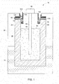
- Fig. 1 is a schematic diagram depicting an exemplary embodiment of a sodium-metal halide battery cell 10.
- the cell 10 has an ion-conductive separator tube 20 disposed in a cell case 30.
- the separator tube 20 is usually made of ⁇ -alumina or ⁇ -alumina.
- the tube 20 defines an anodic chamber 40 between the cell case 30 and the tube 20, and a cathodic chamber 50, inside the tube 30.
- the anodic chamber 40 is usually filled with an anodic material 45, e.g. sodium.
- the cathodic chamber 50 contains a cathode material 55 (e.g. nickel and sodium chloride), and a molten electrolyte, usually sodium chloroaluminate (NaAlCl 4 ).
- An electrically insulating ceramic collar 60 which may be made of alpha-alumina, is situated at a top end 70 of the tube 20.
- a cathode current collector assembly 80 is disposed in the cathode chamber 50, with a cap structure 90, in the top region of the cell.
- the ceramic collar 60 is fitted onto the top end 70 of the separator tube 20, and is sealed by a glass seal 100.
- the collar 60 includes an upper portion 62, and a lower inner portion 64 that abuts against an inner wall of the tube 20, as illustrated in Fig. 1 .
- a metal ring 110 is sometimes disposed.
- the metal ring 110 has two portions; an outer metal ring 120 and an inner metal ring 130, which are joined, respectively, with the upper portion 62 and the lower portion 64 of the ceramic collar 60, by means of the active braze seals 140 and 150.
- the active braze seal 140, the seal 150, or both may be formed by using a suitable braze alloy composition described above.
- the collar 60 and the metal ring 110 may be temporarily held together with an assembly (e.g., a clamp), or by other techniques, until sealing is complete.
- the outer metal ring 120 and the inner metal ring 130 are usually welded shut to seal the cell, after joining with the ceramic collar 60 is completed.
- the outer metal ring 120 can be welded to the cell case 30; and the inner metal ring 130 can be welded to the current collector assembly 80.
- each of the terms “collar” and “ring” is meant to comprise metal or ceramic parts of circular or polygonal shape, and in general, all shapes that are compatible with a particular cell design.
- the braze alloys and the active braze seal formed thereof generally have good stability and chemical resistance within determined parameters at a determined temperature. It is desirable (and in some cases, critical) that the braze seal retains its integrity and properties during several processing steps while manufacturing and using the cell, for example, during a glass-seal process for a ceramic-to-ceramic joint, and during operation of the cell. In some instances, optimum performance of the cell is generally obtained at a temperature greater than about 300 degrees Celsius. In one embodiment, the operating temperature may be in a range from about 270 degrees Celsius to about 450 degrees Celsius. In one embodiment, the glass-seal process is carried out at a temperature of at least about 1000 degrees Celsius.
- the glass-seal process is carried out in a range of from about 1000 degrees Celsius to about 1200 degrees Celsius.
- the bond strength and hermeticity of the seal may depend on several parameters, such as the composition of the braze alloy, the thickness of the thin reaction layer, the composition of the ceramic, and the surface properties of the ceramic.
- an energy storage device includes a plurality of the electrochemical cells as disclosed in previous embodiments.
- the cells are, directly or indirectly, in thermal and/or electrical communication with each other.
- Those of ordinary skill in the art are familiar with the general principles of such devices.
- U.S. Patent 8,110,301 is illustrative, and incorporated by reference herein.
- Some embodiments provide a method for joining a first component to a second component by using a braze alloy composition.
- the method includes the steps of introducing the braze alloy between the first component and the second component to form a brazing structure. (The alloy could be deposited on one or both of the mating surfaces, for example, as also described below).
- the brazing structure can then be heated to form an active braze seal between the first component and the second component.
- the first component includes a ceramic; and the second component includes a metal.
- the braze alloy composition includes nickel, silicon, boron, and an active metal element. At least one additional alloying element, such as chromium, palladium, niobium, molybdenum, iron, and/or tungsten, may further be added.
- the constituents of the braze alloy and their respective amounts (and proportions) are described above.
- a desired alloy powder mixture may be obtained by combining (e.g., mixing and/or milling) commercial metal powders of the constituents in their respective amounts.
- the braze alloy may be employed as a foil, a sheet, a ribbon, a preform, or a wire, or may be formulated into a paste containing water and/or organic fluids.
- the precursor metals or metal alloys may be melted to form homogeneous melts, before being formed and shaped into particles. In some cases, the molten material can be directly shaped into foils, preforms or wires.
- Forming the materials into particles may comprise spraying the alloy melt into a vacuum, or into an inert gas, to obtain a pre-alloyed powder of the braze alloy.
- pellets of the materials may be milled into a desired particle shape and size.
- a layer of the braze alloy is disposed on at least one surface of the first component or the second component to be joined by brazing.
- the layer of the braze alloy in a specific embodiment, is disposed on a surface of the ceramic component.
- the thickness of the alloy layer may be in a range between about 5 microns and about 300 microns. In some specific embodiments, the thickness of the layer ranges from about 10 microns to about 100 microns.
- the layer may be deposited or applied on one or both of the surfaces to be joined, by any suitable technique, e.g. by a printing process or other dispensing processes. In some instances, the foil, wire, or the preform may be suitably positioned for bonding the surfaces to be joined.
- a sheet or foil of the braze alloy may be desirable.
- the thickness of the sheets or foils may usually vary between about 20 microns and about 200 microns.
- the alloys can be rolled into sheets or foils by a suitable technique, for example melt spinning. In one embodiment, the alloy may be melt spun into a sheet or a foil, along with rapid quenching during the spinning.
- the method further includes the step of heating the brazing structure at the brazing temperature.
- the brazing structure When the brazing structure is heated at the brazing temperature, the braze alloy melts and flows over the surfaces.
- the heating can be undertaken in a controlled atmosphere, such as ultra-high pure argon, hydrogen and argon, ultra-high pure helium; or in a vacuum.
- the brazing structure is held at the brazing temperature for a few minutes after melting of the braze alloy, and this period may be referred to as the "brazing time".
- a load can also be applied on the samples.
- the brazing temperature and the brazing time may influence the quality of the active braze seal.
- the brazing temperature is generally less than the melting temperatures of the components to be joined, and higher than the liquidus temperature of the braze alloy.
- the brazing temperature ranges from about 900 degrees Celsius to about 1500 degrees Celsius, for a time period of about 1 minute to about 30 minutes.
- the heating is carried out at the brazing temperature from about 1000 degrees Celsius to about 1300 degrees Celsius, for about 5 minutes to about 15 minutes.
- the alloy melts, and the active metal element (or elements) present in the melt react with the ceramic and form a thin reaction layer at the interface of the ceramic surface and the braze alloy, as described previously.
- the thickness of the reaction layer may range from about 0.1 micron to about 2 microns, depending on the amount of the active metal element available to react with the ceramic, and depending on the surface properties of the ceramic component.
- the brazing structure is then subsequently cooled to room temperature; with a resulting, active braze seal between the two components. In some instances, rapid cooling of the brazing structure is permitted.
- an additional layer containing the active metal element may be first applied to the ceramic component.
- the additional layer may have a high amount of the active metal element, for example more than about 70 weight percent.
- Suitable examples may include nanoparticles of the active metal element, or a hydride of the active metal element, e.g., titanium hydride.
- Some of the embodiments of the present invention advantageously provide braze alloys, which are compositionally stable, and chemically stable in the corrosive environment relative to known braze alloys, and are capable of forming an active braze seal for a ceramic-to-metal joint.
- These braze alloys have high sodium corrosion resistance, and halide corrosion resistance for many end uses.
- the formation of ceramic-to-metal seals for high temperature cells (as discussed above) by active brazing simplifies the overall cell-assembly process, and improves the reliability and performance of the cell.
- the present invention provides advantages to leverage a relatively inexpensive, simple, and rapid process to seal the cell or battery, as compared to currently available methods.
- braze alloy compositions (samples 1-3) were prepared. For each braze sample, as shown in Table 1, individual elements were weighed according to the desired composition. These elements were arc-melted to provide an ingot for each composition. To ensure homogeneity of the compositions, the ingots of the samples were triple-melted. The liquidus temperatures of the 3 samples (sample 1, 2, and 3) were measured using Differential Scanning Calorimeter (DSC). Table 1.
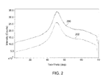
- Fig. 2 shows XRD images of the sample sheets 2, 200 and the sample sheet 3, 202.
- the XRD images show the presence of the amorphous phase of the alloys in both the sample sheets 2 and 3.
- These sheets were further measured for elemental analysis by Electron probe micro-analysis (EPMA).
- the EPMA study confirmed the absence of titanium boride and titanium silicide phases, and indicated the presence of minor amounts of borides and silicides of nickel and chromium.
- sample sheet 2 was then placed between the surfaces of an alpha alumina piece and a nickel piece (parts) to be joined. This assembly was then heated up to about 1200 degrees Celsius for about 10 minutes, and then cooled to room temperature, to form a joint.
- Fig. 3 shows cross-sectional SEM images 300 and 400 of the joint in low and high magnification, respectively.
- SEM image 300 shows a good interface between the alumina piece and the nickel piece.
- SEM image 400 shows an interface between the alumina piece 402 and braze sample 2, 404, at the joint.
- a reaction layer 406 was observed between the braze sample 2 and alumina at the braze-ceramic interface, which indicates a reaction between the braze alloy and the ceramic, and the formation of an active braze seal.
Landscapes
- Chemical & Material Sciences (AREA)
- Engineering & Computer Science (AREA)
- Mechanical Engineering (AREA)
- Electrochemistry (AREA)
- General Chemical & Material Sciences (AREA)
- Chemical Kinetics & Catalysis (AREA)
- Materials Engineering (AREA)
- Organic Chemistry (AREA)
- Ceramic Engineering (AREA)
- Manufacturing & Machinery (AREA)
- Metallurgy (AREA)
- Structural Engineering (AREA)
- Inorganic Chemistry (AREA)
- Ceramic Products (AREA)
- Secondary Cells (AREA)
- Sealing Battery Cases Or Jackets (AREA)
Abstract
Description
- This invention generally relates to a braze composition. In some specific embodiments, the invention relates to a braze composition that provides corrosion-resistant sealing and other benefits to high temperature rechargeable batteries.
- Many types of seal materials have been considered for use in high-temperature rechargeable batteries/cells for joining different components. Sodium/sulfur or sodium/metal halide cells generally include several ceramic and metal components. The ceramic components include an electrically insulating alpha-alumina collar and an ion-conductive electrolyte beta-alumina tube, and are generally joined or bonded via a sealing glass. The metal components include a metallic casing, current collector components, and other metallic components which are often joined by welding or thermal compression bonding (TCB). However, metal-to-ceramic bonding can sometimes present some difficulty, mainly due to thermal stress caused by a mismatch in the coefficient of thermal expansion for the ceramic and metal components.
- The metal-to ceramic bonding is most critical for the reliability and safety of the cell. Many types of seal materials and sealing processes have been considered for joining metal to ceramic components, including ceramic adhesives, brazing, and sintering. However, most of the seals may not be able to withstand high temperatures and corrosive environments.
- A common bonding technique involves multiple steps of metalizing the ceramic component, followed by bonding the metallized ceramic component to the metal component using a thermal compression bond (TCB). The bond strength of such metal-to-ceramic joints is controlled by a wide range of variables, for example, the microstructure of the ceramic component, the metallization of the ceramic component, and various TCB process parameters. In order to ensure good bond strength, the process requires close control of several parameters involved in various process steps. In short, the method is relatively expensive, and complicated, in view of the multiple processing steps, and the difficulty in controlling the processing steps.
- Brazing is another potential technique for making the ceramic-to-metal joints. A braze material is heated above its melting point, and distributed between two or more close-fitting parts by capillary action. However, most of the brazing materials (or braze materials) have limitations that prevent them from fulfilling all of the necessary requirements of high temperature batteries. Moreover, some of the commercial braze materials can be quite expensive themselves; and using them efficiently in various processes can also be costly.
- It may be desirable to develop new braze alloy compositions that have properties and characteristics that meet performance requirements for high temperature rechargeable batteries, and are less complicated and less expensive to process, as compared to the existing sealing methods.
- Various embodiments of the present invention may provide braze alloy compositions for sealing a ceramic to a metal, to form a seal that can withstand corrosive environments.
- In accordance with an embodiment of the invention, a braze alloy composition is disclosed, comprising nickel, silicon, boron, and an active metal element. The braze alloy includes nickel in an amount that is usually greater than about 50 weight percent, and the active metal element in an amount up to about 10 weight percent.
- In one embodiment, an electrochemical cell incorporating the braze alloy composition is disclosed. The braze alloy includes an active metal element that forms a ceramic-to-metal joint, and has good sodium- and halide-resistance at operating temperatures, along with other complimentary mechanical properties; stability at high temperatures; good thermal expansion properties, and the like. In one embodiment, an energy storage device is also disclosed.
- These and other features, aspects, and advantages of the present invention will become better understood when the following detailed description is read with reference to the accompanying drawings, wherein:
-
Fig. 1 is a schematic view showing a cross-section of an electrochemical cell, according to an embodiment; -
Fig. 2 depicts X-ray diffraction patterns for two alloy samples; and -
Fig. 3 shows scanning electron micrographs of cross-sections of a joint between a ceramic component and a metal component. - The invention includes embodiments that relate to a braze alloy composition for sealing an electrochemical cell, for example, a sodium/sulfur or a sodium metal halide battery. The invention also includes embodiments that relate to an electrochemical cell made by using the braze composition. As discussed in detail below, some of the embodiments of the present invention provide a braze alloy for sealing a ceramic component to a metal component, e.g., in an electrochemical cell; along with a metal halide battery formed thereof. These embodiments advantageously provide an improved seal and method for the sealing. Though the present discussion provides examples in the context of a metal halide battery, these processes can be applied to any other application, including ceramic-to-metal or ceramic-to-ceramic joining.
- When introducing elements of various embodiments of the present invention, the articles "a," "an," "the," and "said" are intended to mean that there are one or more of the elements, unless otherwise indicated. The terms "comprising," "including," and "having" are intended to be inclusive, and mean that there may be additional elements other than the listed elements. As used herein, the term "and/or" includes any and all combinations of one or more of the associated listed items. Unless otherwise indicated herein, the terms "disposed on", "deposited on" or "disposed between" refer to both direct contact between layers, objects, and the like, or indirect contact, e.g., having intervening layers therebetween.
- Approximating language, as used herein throughout the specification and claims, may be applied to modify any quantitative representation that could permissibly vary without resulting in a change in the basic function to which it may be related. Accordingly, a value modified by a term such as "about" is not limited to the precise value specified. In some instances, the approximating language may correspond to the precision of an instrument for measuring the value.
- As used herein, the term "liquidus temperature" generally refers to a temperature at which an alloy is transformed from a solid into a molten or viscous state. The liquidus temperature specifies the maximum temperature at which crystals can coexist with the melt in thermodynamic equilibrium. Above the liquidus temperature, the alloy is homogeneous, and below the liquidus temperature, an increasing number of crystals begin to form in the melt with time, depending on the particular alloy. Generally, an alloy, at its liquidus temperature, melts and forms a seal between two components to be joined.
- The liquidus temperature can be contrasted with a "solidus temperature". The solidus temperature quantifies the point at which a material completely solidifies (crystallizes). The liquidus and solidus temperatures do not necessarily align or overlap. If a gap exists between the liquidus and solidus temperatures, then within that gap, the material consists of solid and liquid phases simultaneously (like a "slurry").
- "Sealing" is a function performed by a structure that joins other structures together, to reduce or prevent leakage through the joint between the other structures. The seal structure may also be referred to as a "seal" herein, for the sake of simplicity.
- Typically, "brazing" uses a braze material (usually an alloy) having a lower liquidus temperature than the melting points of the components (i.e. their materials) to be joined. The braze material is brought slightly above its melting (or liquidus) temperature while protected by a suitable atmosphere. The braze material then flows over the components (known as wetting), and is then cooled to join the components together. As used herein, "braze alloy composition" or "braze alloy", "braze material" or "brazing alloy", refers to a composition that has the ability to wet the components to be joined, and to seal them. A braze alloy, for a particular application, should withstand the service conditions required, and should melt at a lower temperature than the base materials; or should melt at a very specific temperature. Conventional braze alloys usually do not wet ceramic surfaces sufficiently to form a strong bond at the interface of a joint. In addition, the alloys may be prone to sodium and halide corrosion.
- As used herein, the term "brazing temperature" refers to a temperature to which a brazing structure is heated to enable a braze alloy to wet the components to be joined, and to form a braze joint or seal. The brazing temperature is often higher than or equal to the liquidus temperature of the braze alloy. In addition, the brazing temperature should be lower than the temperature at which the components to be joined may become chemically, compositionally, and mechanically unstable. There may be several other factors that influence the brazing temperature selection, as those skilled in the art understand.
- Embodiments of the present invention provide a braze alloy composition capable of forming a joint by "active brazing" (described below). In some specific embodiments, the composition also has high resistance to sodium and halide corrosion. The braze alloy composition includes nickel, silicon, boron, and an active metal element, as described herein. Each of the elements of the alloy usually contributes and optimizes at least one property of the overall braze composition. These properties may include liquidus temperature, coefficient of thermal expansion, flowability or wettability of the braze alloy with a ceramic; corrosion resistance, and ease-of-processing. Some of the properties are described below.
- According to most of the embodiments of the invention, the braze alloy composition is a nickel-based alloy. In other words, the alloy contains a relatively high amount of nickel, as compared to the amount of other elements in the alloy. Nickel is relatively inert in a corrosive environment, as compared to other known base metals, e.g. copper, iron, chromium, cobalt etc. Additionally, it is observed that nickel may enhance other properties of the braze alloy, such as the thermal expansion coefficient, and the phase stability. In general, the amount of nickel balances the alloy based on the amounts of the other constituents. In some embodiments of this invention, a suitable level for the amount of nickel may be at least about 20 weight percent, based on the total weight of the braze alloy. In some embodiments, nickel is present in an amount greater than about 50 weight percent. In some embodiments that are preferred for selective end-use applications, the nickel is present from about 60 weight percent to about 90 weight percent, and in some specific embodiments, from about 70 weight percent to about 80 weight percent, based on the total weight of the braze alloy.
- In spite of above discussed properties, nickel-based alloys may have an undesirably high liquidus temperature, i.e., above the required brazing temperature. In order to reduce the liquidus temperature, a melting point depressant may be chosen to form an alloy with nickel, which reduces the melting point of the overall alloy composition. As used herein, the term "melting point depressant" refers to an element or compound which may depress the melting point of the resulting alloy, when added to another element or an alloy. The melting point depressant element may decrease the viscosity and, in turn, increase the flowability (also referred to as wettability) of the braze alloy, at an elevated temperature.
- Suitable examples of the melting point depressant include, but are not limited to, silicon, boron, niobium, palladium, or a combination thereof. According to some of the embodiments of the invention, the braze alloy composition includes silicon and boron, and forms a ternary base alloy, i.e., a Ni-Si-B alloy. Any additional melting point depressant may be added to further adjust the liquidus temperature and/or viscosity of the alloy.
- The present inventors conceived of a balance of nickel and the melting point depressant (silicon and boron) levels that optimized the liquidus temperature requirements and the requirements for corrosion resistance. A suitable, total amount of the melting point depressant may be up to about 20 weight percent, based on the total weight of the braze alloy. In some specific embodiments, the braze alloy includes from about 1 weight percent to about 10 weight percent silicon, based on the total weight of the braze alloy. In some embodiments, the braze alloy includes up to about 10 weight percent boron, based on the total weight of the braze alloy. A suitable range for each of silicon and boron is often from about 2 weight percent to about 10 weight percent. In some embodiments, a small amount of each of silicon or boron (e.g., less than about 5 weight percent) is used, as each of these may be reactive with the active metal element (e.g. titanium), if present in an amount more than the solubility limit of the element in the alloy.
- The braze alloy may include additional melting point depressants, as mentioned above. Examples include niobium and/or palladium. In addition, palladium and niobium may provide good corrosion resistance in a sodium-containing environment. In some embodiments, the braze alloy includes up to about 10 weight percent palladium (e.g., about 0.1 weight percent to about 10 weight percent), based on the total weight of the braze alloy. In some embodiments, the braze alloy includes up to about 5 weight percent niobium (e.g., about 0.1 to about 5 weight percent), based on the total weight of the braze alloy.
- As mentioned above, the concept of "active brazing" is important for embodiments of this invention. Active brazing is a technique often used to join a ceramic to a metal, or a ceramic to a ceramic. Active brazing uses an active metal element that promotes wetting of a ceramic surface, enhancing the capability of providing a hermetic seal. An "active metal element", as used herein, refers to a reactive metal that has high affinity to the oxygen within the ceramic, and thereby reacts with the ceramic. A braze alloy containing an active metal element can also be referred to as an "active braze alloy." The active metal element undergoes a reaction with the ceramic, when the braze alloy is in a molten state, and leads to the formation of a thin reaction layer on the interface of the ceramic and the braze alloy. The thin reaction layer allows the braze alloy to wet the ceramic surface, resulting in the formation of a ceramic-ceramic or a ceramic-metal joint/bond, which may also be referred to as an "active braze seal."
- Thus, an active metal element is an essential constituent of a braze alloy for employing active brazing. A variety of suitable active metal elements may be used to form the active braze alloy. The selection of a suitable active metal element mainly depends on the chemical reaction with the ceramic (e.g., alumina) to form a uniform and continuous reaction layer, and the capability of the active metal element to form an alloy with a base alloy (e.g. a Ni-Si-B alloy). The active metal element for embodiments herein is often titanium. Other suitable examples of the active metal element include, but are not limited to, zirconium, hafnium, and vanadium. A combination of two or more active metal elements may also be used.
- The presence and the amount of the active metal may influence the thickness and the quality of the thin reaction layer, which contributes to the wettability or flowability of the braze alloy, and therefore, the bond strength of the resulting joint. In some embodiments, the active metal is present in an amount less than about 10 weight percent, based on the total weight of the braze alloy. A suitable range is often from about 0.5 weight percent to about 5 weight percent. In some specific embodiments, the active metal is present in an amount ranging from about 1 weight percent to about 3 weight percent, based on the total weight of the braze alloy. The active metal element is generally present in small amounts suitable for improving the wetting of the ceramic surface, and forming the thin reaction layer, for example, less than about 10 microns. A high amount of the active metal layer may cause or accelerate halide corrosion.
- The braze alloy composition may further include at least one additional element. The additional element may provide further adjustments in several required properties of the braze alloy, for example, the coefficient of thermal expansion, liquidus temperature, brazing temperature, corrosion resistance, and the strength of the braze alloy. In one embodiment, the additional element (some of which were mentioned above) can include, but is not limited to, iron, chromium, cobalt, niobium, molybdenum, tungsten, or a combination thereof. In some specific embodiments, the braze alloy includes chromium and iron.
- With respect to the amount of the additional element(s), the braze alloy includes up to about 10 weight percent (e.g., about 0.1%-10%) of the additional elements, based on the total weight of the braze alloy. In some embodiments, the braze alloy includes up to about 10 weight percent chromium (e.g., about 0.1 to about 10 weight percent), based on the total weight of the braze alloy. In some embodiments, the braze alloy includes from about 0.1 weight percent to about 10 weight percent iron, and in some specific embodiments, up to about 5 weight percent iron, based on the total weight of the braze alloy. In some embodiments, the braze alloy includes from about 0.1 weight percent to about 5 weight percent of molybdenum, based on the total weight of the braze alloy.
- In some embodiments, any of the braze alloys described herein may also include cobalt. The addition of cobalt improves the corrosion resistance of the overall composition. The braze alloy may include from about 1 weight percent to about 50 weight percent cobalt, based on the total weight of the braze alloy. In some specific embodiments, the braze alloy includes up to about 10 weight percent of cobalt, based on the total weight of the braze alloy. In some other embodiments, cobalt may replace nickel, and the alloy may be cobalt-based. In these instances, the alloy may include a higher level (from about 40 weight percent to about 80 weight percent) of cobalt, and from about 1 weight percent to about 20 weight percent of nickel.
- As mentioned previously, the active metal element usually exhibits relatively high reactivity with each of boron and silicon. The addition of an active metal element like titanium in a braze alloy has been thought to be technically challenging, due to the possibility of titanium boride and titanium silicide formation, which may be undesirable. The formation of these borides and/or silicides may prevent sufficient amounts of titanium from being available for use as the active element. However, for compositions of the present invention, it was observed that the titanium was not "captured" in titanium boride and/or titanium silicide form.
- The presence of other elements like nickel, chromium and iron, may avoid the formation of the borides/silicides of the active metal element (i.e., titanium) because of higher reactivity of these elements with boron and/or silicon, than with titanium. Furthermore, the possibility of the formation of titanium boride and/or silicide can also be sometimes avoided by controlled processing of the alloy. For example, during material processing of the alloy into a desired form or shape (e.g., rolling into sheets), when the molten alloy was rapidly quenched, for example by melt spinning, it was observed that the alloy was in the glassy amorphous state, and did not include any boride and/or silicide.
Fig. 2 shows X-ray diffraction (XRD) images of two samples formed of alloy compositions, samples 2 and 3, by rapidly quenching during melt spinning. It is clear from the XRDs that the alloys are in an amorphous phase, in both the sheets. - These amorphous alloy samples or "sheets" melt during brazing, and may provide available (free) active metal to react with the ceramic component. Thus, controlled processing of the alloy and brazing process, allows the formation and stabilization of such alloys containing boron, silicon, and titanium.
- It may also be possible during the brazing process that the ceramic may react with boron and/or silicon present in the braze alloy, and form an amorphous phase bond. This bond across the ceramic component and the braze alloy may further enhance the strength of the joint.
- In one embodiment, the braze alloy includes greater than about 50 weight percent nickel, and between about 1 weight percent and about 10 weight percent of each of silicon, boron, chromium, iron, and an active metal element, based on the total weight of the alloy. In some embodiments for selected end-uses, the braze alloy consists essentially of nickel, chromium, iron, at least one of silicon or boron, and an active metal element. In some preferred embodiments, the active metal element comprises titanium, which may be present in an amount between about 1 weight percent and about 5 weight percent, based on the total weight of the alloy.
- As discussed above, the braze alloy has a liquidus temperature lower than the melting temperatures of the components to be joined. In one embodiment, the braze alloy has a liquidus temperature of at least about 850 degrees Celsius. In one embodiment, the braze alloy has a liquidus temperature from about 850 degrees Celsius to about 1300 degrees Celsius, and in some specific embodiments, from about 950 degrees Celsius to about 1250 degrees Celsius.
- Some embodiments of the invention provide an electrochemical cell that comprises a first component and a second component joined to each other by a braze alloy composition. The cell may be a sodium-sulfur cell or a sodium-metal halide cell, for example. As described previously, the braze alloy composition includes nickel, silicon, boron, and an active metal element. At least one additional element, such as chromium, iron, niobium, molybdenum, and/or tungsten may further be added. The constituents of the alloy and their respective amounts are described above.
- As discussed above, the braze alloy composition may provide an active braze seal to join components in the cell. In one embodiment, the first component of the cell comprises a metal or a metal alloy, and the second component comprises a ceramic. The metal component can be a ring that includes nickel. The ceramic component can be a collar that includes an electrically insulating material, for example alumina.
- For example, sodium-sulfur or sodium-metal halide cells may contain the braze alloy composition that forms an active braze seal to form metal-to-ceramic joints. The active braze seal secures an alpha-alumina collar and a nickel ring.
Fig. 1 is a schematic diagram depicting an exemplary embodiment of a sodium-metalhalide battery cell 10. Thecell 10 has an ion-conductive separator tube 20 disposed in acell case 30. Theseparator tube 20 is usually made of β-alumina or β-alumina. Thetube 20 defines ananodic chamber 40 between thecell case 30 and thetube 20, and acathodic chamber 50, inside thetube 30. Theanodic chamber 40 is usually filled with ananodic material 45, e.g. sodium. Thecathodic chamber 50 contains a cathode material 55 (e.g. nickel and sodium chloride), and a molten electrolyte, usually sodium chloroaluminate (NaAlCl4). - An electrically insulating
ceramic collar 60, which may be made of alpha-alumina, is situated at atop end 70 of thetube 20. A cathodecurrent collector assembly 80 is disposed in thecathode chamber 50, with a cap structure 90, in the top region of the cell. Theceramic collar 60 is fitted onto thetop end 70 of theseparator tube 20, and is sealed by aglass seal 100. In one embodiment, thecollar 60 includes anupper portion 62, and a lower inner portion 64 that abuts against an inner wall of thetube 20, as illustrated inFig. 1 . - In order to seal the
cell 10 at the top end (i.e., its upper region), ametal ring 110 is sometimes disposed. Themetal ring 110 has two portions; anouter metal ring 120 and aninner metal ring 130, which are joined, respectively, with theupper portion 62 and the lower portion 64 of theceramic collar 60, by means of the active braze seals 140 and 150. Theactive braze seal 140, theseal 150, or both may be formed by using a suitable braze alloy composition described above. Thecollar 60 and themetal ring 110 may be temporarily held together with an assembly (e.g., a clamp), or by other techniques, until sealing is complete. - The
outer metal ring 120 and theinner metal ring 130 are usually welded shut to seal the cell, after joining with theceramic collar 60 is completed. Theouter metal ring 120 can be welded to thecell case 30; and theinner metal ring 130 can be welded to thecurrent collector assembly 80. - The shape and size of the several components discussed above with reference to
FIG. 1 are only illustrative for the understanding of the cell structure; and are not meant to limit the scope of the invention. The exact position of the seals and the joined components can vary to some degree. Moreover, each of the terms "collar" and "ring" is meant to comprise metal or ceramic parts of circular or polygonal shape, and in general, all shapes that are compatible with a particular cell design. - The braze alloys and the active braze seal formed thereof, generally have good stability and chemical resistance within determined parameters at a determined temperature. It is desirable (and in some cases, critical) that the braze seal retains its integrity and properties during several processing steps while manufacturing and using the cell, for example, during a glass-seal process for a ceramic-to-ceramic joint, and during operation of the cell. In some instances, optimum performance of the cell is generally obtained at a temperature greater than about 300 degrees Celsius. In one embodiment, the operating temperature may be in a range from about 270 degrees Celsius to about 450 degrees Celsius. In one embodiment, the glass-seal process is carried out at a temperature of at least about 1000 degrees Celsius. In some other embodiments, the glass-seal process is carried out in a range of from about 1000 degrees Celsius to about 1200 degrees Celsius. Moreover, the bond strength and hermeticity of the seal may depend on several parameters, such as the composition of the braze alloy, the thickness of the thin reaction layer, the composition of the ceramic, and the surface properties of the ceramic.
- In accordance with some embodiments of this invention, an energy storage device includes a plurality of the electrochemical cells as disclosed in previous embodiments. The cells are, directly or indirectly, in thermal and/or electrical communication with each other. Those of ordinary skill in the art are familiar with the general principles of such devices. For example,
U.S. Patent 8,110,301 is illustrative, and incorporated by reference herein. However, there are many other references which generally describe various types of energy storage devices, and their construction. - Some embodiments provide a method for joining a first component to a second component by using a braze alloy composition. The method includes the steps of introducing the braze alloy between the first component and the second component to form a brazing structure. (The alloy could be deposited on one or both of the mating surfaces, for example, as also described below). The brazing structure can then be heated to form an active braze seal between the first component and the second component. In one embodiment, the first component includes a ceramic; and the second component includes a metal. The braze alloy composition includes nickel, silicon, boron, and an active metal element. At least one additional alloying element, such as chromium, palladium, niobium, molybdenum, iron, and/or tungsten, may further be added. The constituents of the braze alloy and their respective amounts (and proportions) are described above.
- In the general preparation of the braze alloy, a desired alloy powder mixture may be obtained by combining (e.g., mixing and/or milling) commercial metal powders of the constituents in their respective amounts. In some embodiments, the braze alloy may be employed as a foil, a sheet, a ribbon, a preform, or a wire, or may be formulated into a paste containing water and/or organic fluids. In some embodiments, the precursor metals or metal alloys may be melted to form homogeneous melts, before being formed and shaped into particles. In some cases, the molten material can be directly shaped into foils, preforms or wires. Forming the materials into particles, initially, may comprise spraying the alloy melt into a vacuum, or into an inert gas, to obtain a pre-alloyed powder of the braze alloy. In other cases, pellets of the materials may be milled into a desired particle shape and size.
- In one embodiment, a layer of the braze alloy is disposed on at least one surface of the first component or the second component to be joined by brazing. The layer of the braze alloy, in a specific embodiment, is disposed on a surface of the ceramic component. The thickness of the alloy layer may be in a range between about 5 microns and about 300 microns. In some specific embodiments, the thickness of the layer ranges from about 10 microns to about 100 microns. The layer may be deposited or applied on one or both of the surfaces to be joined, by any suitable technique, e.g. by a printing process or other dispensing processes. In some instances, the foil, wire, or the preform may be suitably positioned for bonding the surfaces to be joined.
- In some specific embodiments, a sheet or foil of the braze alloy may be desirable. The thickness of the sheets or foils may usually vary between about 20 microns and about 200 microns. The alloys can be rolled into sheets or foils by a suitable technique, for example melt spinning. In one embodiment, the alloy may be melt spun into a sheet or a foil, along with rapid quenching during the spinning.
- In a typical embodiment, the method further includes the step of heating the brazing structure at the brazing temperature. When the brazing structure is heated at the brazing temperature, the braze alloy melts and flows over the surfaces. The heating can be undertaken in a controlled atmosphere, such as ultra-high pure argon, hydrogen and argon, ultra-high pure helium; or in a vacuum. To achieve good flow and wetting of the braze alloy, the brazing structure is held at the brazing temperature for a few minutes after melting of the braze alloy, and this period may be referred to as the "brazing time". During the brazing process, a load can also be applied on the samples.
- The brazing temperature and the brazing time may influence the quality of the active braze seal. The brazing temperature is generally less than the melting temperatures of the components to be joined, and higher than the liquidus temperature of the braze alloy. In one embodiment, the brazing temperature ranges from about 900 degrees Celsius to about 1500 degrees Celsius, for a time period of about 1 minute to about 30 minutes. In a specific embodiment, the heating is carried out at the brazing temperature from about 1000 degrees Celsius to about 1300 degrees Celsius, for about 5 minutes to about 15 minutes.
- During brazing, the alloy melts, and the active metal element (or elements) present in the melt react with the ceramic and form a thin reaction layer at the interface of the ceramic surface and the braze alloy, as described previously. The thickness of the reaction layer may range from about 0.1 micron to about 2 microns, depending on the amount of the active metal element available to react with the ceramic, and depending on the surface properties of the ceramic component. In a typical sequence, the brazing structure is then subsequently cooled to room temperature; with a resulting, active braze seal between the two components. In some instances, rapid cooling of the brazing structure is permitted.
- In some embodiments, an additional layer containing the active metal element may be first applied to the ceramic component. The additional layer may have a high amount of the active metal element, for example more than about 70 weight percent. Suitable examples may include nanoparticles of the active metal element, or a hydride of the active metal element, e.g., titanium hydride.
- Some of the embodiments of the present invention advantageously provide braze alloys, which are compositionally stable, and chemically stable in the corrosive environment relative to known braze alloys, and are capable of forming an active braze seal for a ceramic-to-metal joint. These braze alloys have high sodium corrosion resistance, and halide corrosion resistance for many end uses. The formation of ceramic-to-metal seals for high temperature cells (as discussed above) by active brazing simplifies the overall cell-assembly process, and improves the reliability and performance of the cell. The present invention provides advantages to leverage a relatively inexpensive, simple, and rapid process to seal the cell or battery, as compared to currently available methods.
- The examples that follow are merely illustrative, and should not be construed to be any sort of limitation on the scope of the claimed invention. Unless specified otherwise, all ingredients may be commercially available from such common chemical suppliers as Alpha Aesar, Inc. (Ward Hill, Massachusetts), Sigma Aldrich (St. Louis, Missouri), Spectrum Chemical Mfg. Corp. (Gardena, California), and the like.
- 3 braze alloy compositions (samples 1-3) were prepared. For each braze sample, as shown in Table 1, individual elements were weighed according to the desired composition. These elements were arc-melted to provide an ingot for each composition. To ensure homogeneity of the compositions, the ingots of the samples were triple-melted. The liquidus temperatures of the 3 samples (sample 1, 2, and 3) were measured using Differential Scanning Calorimeter (DSC).
Table 1. Braze Samples Braze alloy composition (weight percent) Liquidus temperature (°C) Sample 1 Ni-7Cr-4.5Fe-4.5Si-3.2B-1.25Ti 1069 Sample 2 Ni-7Cr-4.5Fe-4.5Si-3.2B-2Ti 1090 Sample 3 Ni-7Cr-4.SFe-4.5Si-3.2B-3Ti 1104 - Each ingot of samples 2 and 3 was melt-spun into approximately a 75 micron-thick sheet, and rapidly quenched during spinning.
Fig. 2 shows XRD images of thesample sheets 2, 200 and thesample sheet 3, 202. The XRD images show the presence of the amorphous phase of the alloys in both the sample sheets 2 and 3. These sheets were further measured for elemental analysis by Electron probe micro-analysis (EPMA). The EPMA study confirmed the absence of titanium boride and titanium silicide phases, and indicated the presence of minor amounts of borides and silicides of nickel and chromium. - The sample sheet 2 was then placed between the surfaces of an alpha alumina piece and a nickel piece (parts) to be joined. This assembly was then heated up to about 1200 degrees Celsius for about 10 minutes, and then cooled to room temperature, to form a joint.
-
Fig. 3 showscross-sectional SEM images SEM image 300 shows a good interface between the alumina piece and the nickel piece.SEM image 400 shows an interface between thealumina piece 402 andbraze sample 2, 404, at the joint. Areaction layer 406 was observed between the braze sample 2 and alumina at the braze-ceramic interface, which indicates a reaction between the braze alloy and the ceramic, and the formation of an active braze seal. - Various aspects and embodiments of the present invention are defined by the following numbered clauses:
- 1. A braze alloy composition, comprising nickel, silicon, boron, and an active metal element, wherein nickel is present in an amount greater than about 50 weight percent, and the active metal element is present in an amount up to about 10 weight percent, based on the total weight of the braze alloy composition.
- 2. The braze alloy composition of clause 1, comprising from about 60 weight percent to about 90 weight percent nickel.
- 3. The braze alloy composition of any preceding clause, comprising from about 1 weight percent to about 10 weight percent boron.
- 4. The braze alloy composition of any preceding clause, comprising from about 1 weight percent to about 10 weight percent of silicon.
- 5. The braze alloy composition of any preceding clause, comprising from about 0.5 weight percent to about 5 weight percent of the active metal element.
- 6. The braze alloy composition of any preceding clause, comprising from about 1 weight percent to about 3 weight percent of the active metal element.
- 7. The braze alloy composition of any preceding clause, wherein the active metal element comprises titanium, zirconium, hafnium, vanadium, or a combination thereof.
- 8. The braze alloy composition of any preceding clause, wherein the active metal element comprises titanium.
- 9. The braze alloy composition of any preceding clause, wherein the brazing alloy comprises at least one additional element.
- 10. The braze alloy composition of any preceding clause, wherein the additional element comprises chromium, niobium, cobalt, iron, molybdenum, tungsten, tantalum, or a combination thereof.
- 11. The braze alloy composition of any preceding clause, comprising from about 1 weight percent to about 50 weight percent cobalt.
- 12. The braze alloy composition of any preceding clause, comprising from about 0.1 weight percent to about 10 weight percent chromium.
- 13. The braze alloy composition of any preceding clause, comprising from about 0.1 weight percent to about 10 weight percent iron.
- 14. The braze alloy composition of any preceding clause, comprising from about 0.1 weight percent to about 5 weight percent molybdenum.
- 15. The braze alloy composition of any preceding clause, having a liquidus temperature of at least about 850 degrees Celsius.
- 16. The braze alloy composition of any preceding clause, having a liquidus temperature in a range from about 850 degrees Celsius to about 1250 degrees Celsius.
- 17. A braze alloy composition, comprising greater than about 50 weight percent nickel, and from about 1 weight percent to about 10 weight percent each of chromium, iron, silicon, boron, and an active metal element, based on the total weight of the braze alloy composition.
- 18. An electrochemical cell, comprising a first component and a second component joined to each other by the braze alloy composition comprising nickel, silicon, boron, and an active metal element, wherein nickel is present in an amount greater than about 50 weight percent, and the active metal element is present in an amount up to about 10 weight percent, based on the total weight of the braze alloy composition.
- 19. The electrochemical cell of any preceding clause, wherein the braze alloy composition provides an active braze seal that joins the first component to the second component.
- 20. The electrochemical cell of any preceding clause, wherein the first component comprises a metal, and the second component comprises a ceramic.
- 21. The electrochemical cell of any preceding clause, wherein the first component comprises nickel.
- 22. The electrochemical cell of any preceding clause, wherein the second component comprises alumina.
- 23. An energy storage device comprising a plurality of electrochemical cells as defined in any preceding clause 18.
Claims (15)
- A braze alloy composition, comprising nickel, silicon, boron, and an active metal element, wherein nickel is present in an amount greater than about 50 weight percent, and the active metal element is present in an amount up to about 10 weight percent, based on the total weight of the braze alloy composition.
- The braze alloy composition of claim 1, comprising from about 60 weight percent to about 90 weight percent nickel.
- The braze alloy composition of claim 1 or claim 2, comprising from about 1 weight percent to about 10 weight percent boron.
- The braze alloy composition of any preceding claim, comprising from about 1 weight percent to about 10 weight percent of silicon.
- The braze alloy composition of any preceding claim, comprising from about 0.5 weight percent to about 5 weight percent of the active metal element.
- The braze alloy composition of any preceding claim, wherein the active metal element comprises titanium, zirconium, hafnium, vanadium, or a combination thereof.
- The braze alloy composition of any preceding claim, wherein the brazing alloy comprises at least one additional element.
- The braze alloy composition of claim 7, wherein the additional element comprises chromium, niobium, cobalt, iron, molybdenum, tungsten, tantalum, or combinations thereof.
- The braze alloy composition of claim 8, comprising from about 1 weight percent to about 50 weight percent cobalt.
- The braze alloy composition of claim 8 or claim 9, comprising from about 0.1 weight percent to about 10 weight percent chromium.
- The braze alloy composition of any one of claims 8 to 10, comprising from about 0.1 weight percent to about 10 weight percent iron.
- The braze alloy composition of any one of claims 8 to 11, comprising from about 0.1 weight percent to about 5 weight percent molybdenum.
- A braze alloy composition, comprising greater than about 50 weight percent nickel, and from about 1 weight percent to about 10 weight percent each of chromium, iron, silicon, boron, and an active metal element, based on the total weight of the braze alloy composition.
- An electrochemical cell, comprising a first component and a second component joined to each other by the braze alloy composition comprising nickel, silicon, boron, and an active metal element, wherein nickel is present in an amount greater than about 50 weight percent, and the active metal element is present in an amount up to about 10 weight percent, based on the total weight of the braze alloy composition.
- An energy storage device comprising a plurality of electrochemical cells as defined in claim 14.
Applications Claiming Priority (3)
| Application Number | Priority Date | Filing Date | Title |
|---|---|---|---|
| US201261651817P | 2012-05-25 | 2012-05-25 | |
| US13/538,203 US10105795B2 (en) | 2012-05-25 | 2012-06-29 | Braze compositions, and related devices |
| US13/600,333 US20130316226A1 (en) | 2012-05-25 | 2012-08-31 | Braze compositions, and related devices |
Publications (2)
| Publication Number | Publication Date |
|---|---|
| EP2666582A1 true EP2666582A1 (en) | 2013-11-27 |
| EP2666582B1 EP2666582B1 (en) | 2019-07-03 |
Family
ID=49621719
Family Applications (2)
| Application Number | Title | Priority Date | Filing Date |
|---|---|---|---|
| EP13169240.2A Active EP2666581B1 (en) | 2012-05-25 | 2013-05-24 | Braze compositions, and related devices |
| EP13169250.1A Active EP2666582B1 (en) | 2012-05-25 | 2013-05-24 | Braze compositions, and related devices |
Family Applications Before (1)
| Application Number | Title | Priority Date | Filing Date |
|---|---|---|---|
| EP13169240.2A Active EP2666581B1 (en) | 2012-05-25 | 2013-05-24 | Braze compositions, and related devices |
Country Status (6)
| Country | Link |
|---|---|
| US (5) | US10105795B2 (en) |
| EP (2) | EP2666581B1 (en) |
| JP (2) | JP6266232B2 (en) |
| KR (2) | KR20130132293A (en) |
| CN (2) | CN103418932A (en) |
| BR (3) | BR102013012941B8 (en) |
Cited By (3)
| Publication number | Priority date | Publication date | Assignee | Title |
|---|---|---|---|---|
| WO2014193674A1 (en) * | 2013-05-31 | 2014-12-04 | General Electric Company | A brazing structure, and related processes and devices |
| US9548518B2 (en) * | 2014-12-16 | 2017-01-17 | General Electric Company | Methods for joining ceramic and metallic structures |
| US20170043424A1 (en) * | 2015-08-10 | 2017-02-16 | General Electric Company | Process for joining metallic and ceramic structures |
Families Citing this family (32)
| Publication number | Priority date | Publication date | Assignee | Title |
|---|---|---|---|---|
| JP5310714B2 (en) * | 2010-12-28 | 2013-10-09 | ダイキン工業株式会社 | Metal tube joining structure and heat exchanger |
| JP5997529B2 (en) * | 2012-07-24 | 2016-09-28 | 理想科学工業株式会社 | Paper feeder |
| US11387497B2 (en) | 2012-10-18 | 2022-07-12 | Ambri Inc. | Electrochemical energy storage devices |
| US10541451B2 (en) | 2012-10-18 | 2020-01-21 | Ambri Inc. | Electrochemical energy storage devices |
| US11211641B2 (en) * | 2012-10-18 | 2021-12-28 | Ambri Inc. | Electrochemical energy storage devices |
| US11721841B2 (en) | 2012-10-18 | 2023-08-08 | Ambri Inc. | Electrochemical energy storage devices |
| US9806380B2 (en) | 2013-05-31 | 2017-10-31 | General Electric Company | High temperature electrochemical cell structures, and methods for making |
| US12347832B2 (en) | 2013-09-18 | 2025-07-01 | Ambri, LLC | Electrochemical energy storage devices |
| DK3058605T3 (en) * | 2013-10-16 | 2024-03-04 | Ambri Inc | SEALS FOR DEVICES OF REACTIVE HIGH TEMPERATURE MATERIAL |
| WO2015058165A1 (en) | 2013-10-17 | 2015-04-23 | Ambri Inc. | Battery management systems for energy storage devices |
| US12142735B1 (en) | 2013-11-01 | 2024-11-12 | Ambri, Inc. | Thermal management of liquid metal batteries |
| JP6480806B2 (en) * | 2014-05-23 | 2019-03-13 | ゼネラル・エレクトリック・カンパニイ | Method for bonding ceramic and metal and sealing structure thereof |
| US10471531B2 (en) * | 2014-12-31 | 2019-11-12 | Component Re-Engineering Company, Inc. | High temperature resistant silicon joint for the joining of ceramics |
| WO2016141354A2 (en) | 2015-03-05 | 2016-09-09 | Ambri Inc. | Ceramic materials and seals for high temperature reactive material devices |
| CN105458551B (en) * | 2015-12-28 | 2018-01-30 | 哈尔滨工业大学 | A kind of method of the assistant brazing of high-temp solder containing tantalum of ceramic soldering and metal |
| CN105479037B (en) * | 2016-01-07 | 2018-04-13 | 厦门大学 | A kind of nickel-based boron-free solder and preparation method thereof |
| EP3225352B1 (en) | 2016-03-30 | 2020-08-19 | General Electric Company | Eutectic brazing compositions, and related processes and devices |
| EP3225351B1 (en) | 2016-03-30 | 2020-05-06 | General Electric Company | Brazing compositions for ductile braze structures, and related processes and devices |
| CN105946481A (en) * | 2016-06-20 | 2016-09-21 | 云南航天工业有限公司 | Pulling-out type fast connecting passageway |
| US11929466B2 (en) | 2016-09-07 | 2024-03-12 | Ambri Inc. | Electrochemical energy storage devices |
| US20180076465A1 (en) * | 2016-09-12 | 2018-03-15 | Johnson & Johnson Vision Care, Inc. | Tubular form biomedical device batteries with electroless sealing |
| US10734668B2 (en) | 2016-09-12 | 2020-08-04 | Johnson & Johnson Vision Care, Inc. | Tubular form biomedical device batteries |
| US10583302B2 (en) | 2016-09-23 | 2020-03-10 | Greatbatch Ltd. | Gold wetting on ceramic surfaces upon coating with titanium hydride |
| CN110731027B (en) | 2017-04-07 | 2024-06-18 | 安保瑞公司 | Molten salt battery with solid metal cathode |
| JP6860410B2 (en) * | 2017-04-25 | 2021-04-14 | 山陽特殊製鋼株式会社 | Ni—Cr based alloy brazing material containing a small amount of V |
| US20190039141A1 (en) * | 2017-08-07 | 2019-02-07 | General Electric Company | Pre-sintered preform and process |
| JP7170431B2 (en) * | 2017-09-25 | 2022-11-14 | 株式会社東芝 | Container and method for closing opening in container |
| US11648620B2 (en) * | 2017-11-29 | 2023-05-16 | Watlow Electric Manufacturing Company | Semiconductor processing equipment with high temperature resistant nickel alloy joints and methods for making same |
| KR102004218B1 (en) * | 2018-03-08 | 2019-07-26 | 부산대학교 산학협력단 | Cu-based filler metal composition for sodium-based secondary battery and method for bonding ceramic-metal using the same |
| WO2020044594A1 (en) * | 2018-08-28 | 2020-03-05 | 三菱マテリアル株式会社 | Copper/ceramic bonded body, insulation circuit board, method for producing copper/ceramic bonded body, and method for manufacturing insulation circuit board |
| CN109053208A (en) * | 2018-09-03 | 2018-12-21 | 威海圆环先进陶瓷股份有限公司 | A kind of preparation process of active metallization soldering silicon nitride ceramics copper-clad base plate |
| WO2020131617A1 (en) | 2018-12-17 | 2020-06-25 | Ambri Inc. | High temperature energy storage systems and methods |
Citations (7)
| Publication number | Priority date | Publication date | Assignee | Title |
|---|---|---|---|---|
| US4490437A (en) * | 1982-09-20 | 1984-12-25 | Gte Products Corporation | Ductile nickel based brazing alloy foil |
| US4900638A (en) * | 1987-04-10 | 1990-02-13 | Vacuumschmelze Gmbh | Nickel-base solder for high-temperature solder joints |
| EP0428275A1 (en) * | 1989-11-13 | 1991-05-22 | Ford Motor Company Limited | Braze material for joining ceramic to metal and ceramic to ceramic surfaces |
| EP0726238A2 (en) * | 1995-02-09 | 1996-08-14 | Ngk Insulators, Ltd. | Joined articles, corrosion-resistant joining materials and process for producing joined articles |
| WO1999065642A1 (en) * | 1998-06-15 | 1999-12-23 | Bi-Patent Holding S.A. | Brazing composition and seal for electrochemical cell |
| US8110301B2 (en) | 2006-12-19 | 2012-02-07 | General Electric Company | Energy storage device and cell configuration therefor |
| US20120063911A1 (en) * | 2009-03-31 | 2012-03-15 | Alstom Technology Ltd | Dual brazing alloy element, process for producing it and uses thereof |
Family Cites Families (64)
| Publication number | Priority date | Publication date | Assignee | Title |
|---|---|---|---|---|
| US2240064A (en) | 1940-09-06 | 1941-04-29 | Driver Co Wilbur B | Alloy for metal to glass seals |
| US2992918A (en) | 1953-11-12 | 1961-07-18 | Kanthal Ab | Electrical resistors and materials therefor |
| US2856281A (en) | 1954-10-05 | 1958-10-14 | Solar Aircraft Co | High temperature brazing alloys |
| DE2326433C2 (en) | 1973-05-24 | 1975-01-30 | Vereinigte Deutsche Metallwerke Ag, 6000 Frankfurt | Copper-nickel smoldering filler material for gas-shielded welding |
| GB1538110A (en) * | 1976-10-14 | 1979-01-10 | Bones R | Electric cells |
| JPS5893586A (en) | 1981-11-27 | 1983-06-03 | Hitachi Ltd | Joining method for heat-resistant alloys |
| DE3374921D1 (en) | 1982-09-24 | 1988-01-28 | Gte Prod Corp | Ductile brazing alloy containing reactive metals and precious metals |
| US4497772A (en) | 1982-09-24 | 1985-02-05 | Gte Products Corporation | Reactive metal-palladium-copper-nickel brazing alloys |
| US4486386A (en) | 1982-09-24 | 1984-12-04 | Gte Products Corporation | Reactive metal-palladium-gold brazing alloys |
| US4603090A (en) | 1984-04-05 | 1986-07-29 | Gte Products Corporation | Ductile titanium-indium-copper brazing alloy |
| US4621761A (en) | 1984-12-04 | 1986-11-11 | The United States Of America As Represented By The United States Department Of Energy | Process for forming unusually strong joints between metals and ceramics by brazing at temperatures that do no exceed 750 degree C. |
| US4639388A (en) | 1985-02-12 | 1987-01-27 | Chromalloy American Corporation | Ceramic-metal composites |
| JPS6216896A (en) | 1985-07-17 | 1987-01-26 | Tanaka Kikinzoku Kogyo Kk | Brazing filler metal for ceramics |
| US4740429A (en) | 1985-07-22 | 1988-04-26 | Ngk Insulators, Ltd. | Metal-ceramic joined articles |
| JPS62212095A (en) | 1986-03-13 | 1987-09-18 | Tanaka Kikinzoku Kogyo Kk | Brazing filler metal |
| JPS62275596A (en) | 1986-05-21 | 1987-11-30 | Tanaka Kikinzoku Kogyo Kk | Brazing filler metal |
| JPS63317284A (en) | 1987-06-18 | 1988-12-26 | Tanaka Kikinzoku Kogyo Kk | Gold alloy filler metal for brazing |
| US5392982A (en) | 1988-11-29 | 1995-02-28 | Li; Chou H. | Ceramic bonding method |
| JPH0347901A (en) | 1989-07-14 | 1991-02-28 | Showa Denko Kk | Material for adhesion |
| JP3004379B2 (en) | 1991-04-09 | 2000-01-31 | 三菱重工業株式会社 | Joining method of ceramics and metal |
| US5183636A (en) * | 1991-07-01 | 1993-02-02 | Wall Colmonoy Corporation | Braze filler metal with enhanced corrosion resistance |
| US5186380A (en) | 1991-08-15 | 1993-02-16 | Handy & Harman | Titanium hydride coated brazing product |
| JPH05285689A (en) | 1992-04-06 | 1993-11-02 | Hitachi Cable Ltd | Clad brazing filler metal |
| US5600530A (en) | 1992-08-04 | 1997-02-04 | The Morgan Crucible Company Plc | Electrostatic chuck |
| JPH0691389A (en) | 1992-08-05 | 1994-04-05 | Tanaka Kikinzoku Kogyo Kk | Palladium braze alloy |
| JP2820613B2 (en) | 1994-03-29 | 1998-11-05 | 新日本製鐵株式会社 | Liquid phase diffusion bonding alloy foil for heat resistant materials that can be bonded in oxidizing atmosphere |
| JPH10502129A (en) | 1994-06-24 | 1998-02-24 | テレダイン インダストリーズ インコーポレイテッド | Nickel based alloys and methods |
| JP3336485B2 (en) * | 1994-10-26 | 2002-10-21 | 日本特殊陶業株式会社 | Tappet |
| US6523605B2 (en) | 1996-05-02 | 2003-02-25 | The Furukawa Electric Co., Ltd. | Heat exchanger made of an aluminum alloy |
| JP3243184B2 (en) | 1996-07-12 | 2002-01-07 | 新日本製鐵株式会社 | Alloy foil for liquid phase diffusion bonding that can be bonded in oxidizing atmosphere |
| JPH10193210A (en) | 1997-01-09 | 1998-07-28 | Mitsubishi Materials Corp | Cemented carbide cutting tool with excellent brazing joint strength |
| US6149051A (en) | 1997-08-07 | 2000-11-21 | Alliedsignal Inc. | Braze titanium |
| US6605371B1 (en) | 1998-09-28 | 2003-08-12 | Sumitomo Special Metals Co., Ltd. | Brazing alloy for stainless steel, structure braze-assembled with the brazing alloy, and brazing material for stainless steel |
| US6131797A (en) | 1998-11-16 | 2000-10-17 | Alliedsignal Inc. | Method for joining ceramic to metal |
| JP2001321961A (en) | 2000-05-10 | 2001-11-20 | Nippon Steel Corp | Liquid phase diffusion joints with excellent tensile strength characteristics and joining method |
| US6528123B1 (en) | 2000-06-28 | 2003-03-04 | Sandia Corporation | Coating system to permit direct brazing of ceramics |
| US6719892B2 (en) | 2001-05-04 | 2004-04-13 | United Technologies Corporation | Selective removal of brazing compound from joined assemblies |
| KR100885696B1 (en) * | 2002-05-07 | 2009-02-26 | 더 리전트 오브 더 유니버시티 오브 캘리포니아 | Electrochemical cell stack assembly |
| US7436058B2 (en) | 2002-05-09 | 2008-10-14 | Intel Corporation | Reactive solder material |
| JP4394477B2 (en) * | 2003-03-27 | 2010-01-06 | Dowaホールディングス株式会社 | Method for producing metal / ceramic bonding substrate |
| DE10335947A1 (en) * | 2003-08-04 | 2005-03-17 | Vacuumschmelze Gmbh & Co. Kg | Copper brazing alloy and brazing method |
| US20050067061A1 (en) | 2003-09-26 | 2005-03-31 | General Electric Company | Nickel-based braze alloy compositions and related processes and articles |
| US9166214B2 (en) | 2004-07-15 | 2015-10-20 | General Electric Company | Seal ring and associated method |
| CN100434218C (en) | 2004-09-30 | 2008-11-19 | 太原理工大学 | Application method of surface alloyed ceramics |
| RU2278011C1 (en) | 2004-11-16 | 2006-06-20 | Федеральное государственное унитарное предприятие "Всероссийский научно-исследовательский институт авиационных материалов" (ФГУП "ВИАМ") | Nickel base solder |
| JP2008522370A (en) | 2004-11-30 | 2008-06-26 | ザ、リージェンツ、オブ、ザ、ユニバーシティ、オブ、カリフォルニア | Sealed joint structure for electrochemical devices |
| DE102005048213A1 (en) | 2005-09-29 | 2007-04-05 | Elringklinger Ag | Sealing arrangement for a fuel cell stack comprises a housing part of a first fuel cell unit made from a metallic material provided with a coating made from a ceramic material |
| US8703044B2 (en) | 2006-01-03 | 2014-04-22 | General Electric Company | Machine components and methods of fabricating and repairing |
| DE102006016001B4 (en) | 2006-03-30 | 2009-09-03 | Elringklinger Ag | fuel cell stack |
| US7815848B2 (en) | 2006-05-08 | 2010-10-19 | Huntington Alloys Corporation | Corrosion resistant alloy and components made therefrom |
| US7445294B2 (en) | 2006-08-11 | 2008-11-04 | Hall David R | Attack tool |
| SE530724C2 (en) | 2006-11-17 | 2008-08-26 | Alfa Laval Corp Ab | Solder material, method for soldering with this solder material, soldered object produced by the method and solder paste comprising the solder material |
| SE531988C2 (en) | 2006-11-17 | 2009-09-22 | Alfa Laval Corp Ab | Soldering material and method of soldering with this material |
| CN100577344C (en) | 2006-12-29 | 2010-01-06 | 哈尔滨工业大学 | A kind of active medium-temperature copper-based solder and preparation method thereof |
| US20090041611A1 (en) * | 2007-08-07 | 2009-02-12 | General Electric Company | Braze alloy composition with enhanced oxidation resistance and methods of using the same |
| CN101172880A (en) | 2007-09-21 | 2008-05-07 | 江苏科技大学 | Titanium group high temperature amorphous solder of hard solder Si*N* ceramic and method for producing the same |
| JP2009260023A (en) | 2008-04-16 | 2009-11-05 | Seiko Instruments Inc | Electrochemical cell, manufacturing method thereof, and sealing member |
| JP2009283313A (en) | 2008-05-22 | 2009-12-03 | Toshiba Corp | Joining material for vacuum bulb |
| CN101327551B (en) * | 2008-06-05 | 2010-06-30 | 华中科技大学 | A brazing material, its preparation method and its brazing method |
| FR2936176B1 (en) | 2008-09-22 | 2011-06-03 | Commissariat Energie Atomique | MEDIUM REFRACTORY ASSEMBLY METHOD OF NON-REAGENT SIN BASED MATERIAL MATERIALS, BRAZING COMPOSITIONS, AND JOINT AND ASSEMBLY OBTAINED THEREBY |
| US8629592B2 (en) | 2009-06-25 | 2014-01-14 | General Electric Company | Hermetic sealing assembly and electrical device including the same |
| CN101745753B (en) | 2009-12-18 | 2012-01-18 | 西北有色金属研究院 | Silver-free copper-based brazing material and production technology thereof |
| US8852786B2 (en) * | 2010-12-22 | 2014-10-07 | General Electric Company | Ceramic-metal sealing structure, and associated method |
| US20130224561A1 (en) | 2012-02-29 | 2013-08-29 | General Electric Company | Braze compositions, and related articles and methods |
-
2012
- 2012-06-29 US US13/538,203 patent/US10105795B2/en active Active
- 2012-08-31 US US13/600,333 patent/US20130316226A1/en not_active Abandoned
- 2012-09-27 US US13/628,548 patent/US20130315659A1/en not_active Abandoned
-
2013
- 2013-05-22 JP JP2013107544A patent/JP6266232B2/en active Active
- 2013-05-22 JP JP2013107545A patent/JP6266233B2/en active Active
- 2013-05-22 KR KR1020130057607A patent/KR20130132293A/en not_active Ceased
- 2013-05-22 KR KR1020130057600A patent/KR102162549B1/en active Active
- 2013-05-24 CN CN2013101961374A patent/CN103418932A/en active Pending
- 2013-05-24 EP EP13169240.2A patent/EP2666581B1/en active Active
- 2013-05-24 EP EP13169250.1A patent/EP2666582B1/en active Active
- 2013-05-24 BR BR102013012941A patent/BR102013012941B8/en active IP Right Grant
- 2013-05-24 CN CN2013101960174A patent/CN103418931A/en active Pending
- 2013-05-24 BR BR102013012938-0A patent/BR102013012938B1/en active IP Right Grant
- 2013-09-09 BR BR102013022970-9A patent/BR102013022970A2/en not_active Application Discontinuation
-
2016
- 2016-08-15 US US15/236,979 patent/US20160354869A1/en not_active Abandoned
-
2018
- 2018-09-06 US US16/124,120 patent/US20190001445A1/en not_active Abandoned
Patent Citations (7)
| Publication number | Priority date | Publication date | Assignee | Title |
|---|---|---|---|---|
| US4490437A (en) * | 1982-09-20 | 1984-12-25 | Gte Products Corporation | Ductile nickel based brazing alloy foil |
| US4900638A (en) * | 1987-04-10 | 1990-02-13 | Vacuumschmelze Gmbh | Nickel-base solder for high-temperature solder joints |
| EP0428275A1 (en) * | 1989-11-13 | 1991-05-22 | Ford Motor Company Limited | Braze material for joining ceramic to metal and ceramic to ceramic surfaces |
| EP0726238A2 (en) * | 1995-02-09 | 1996-08-14 | Ngk Insulators, Ltd. | Joined articles, corrosion-resistant joining materials and process for producing joined articles |
| WO1999065642A1 (en) * | 1998-06-15 | 1999-12-23 | Bi-Patent Holding S.A. | Brazing composition and seal for electrochemical cell |
| US8110301B2 (en) | 2006-12-19 | 2012-02-07 | General Electric Company | Energy storage device and cell configuration therefor |
| US20120063911A1 (en) * | 2009-03-31 | 2012-03-15 | Alstom Technology Ltd | Dual brazing alloy element, process for producing it and uses thereof |
Cited By (3)
| Publication number | Priority date | Publication date | Assignee | Title |
|---|---|---|---|---|
| WO2014193674A1 (en) * | 2013-05-31 | 2014-12-04 | General Electric Company | A brazing structure, and related processes and devices |
| US9548518B2 (en) * | 2014-12-16 | 2017-01-17 | General Electric Company | Methods for joining ceramic and metallic structures |
| US20170043424A1 (en) * | 2015-08-10 | 2017-02-16 | General Electric Company | Process for joining metallic and ceramic structures |
Also Published As
| Publication number | Publication date |
|---|---|
| KR102162549B1 (en) | 2020-10-08 |
| JP6266232B2 (en) | 2018-01-24 |
| US20160354869A1 (en) | 2016-12-08 |
| BR102013012938B1 (en) | 2019-04-30 |
| EP2666582B1 (en) | 2019-07-03 |
| KR20130132292A (en) | 2013-12-04 |
| BR102013012941A8 (en) | 2016-04-26 |
| BR102013012941B8 (en) | 2019-05-14 |
| JP2014012295A (en) | 2014-01-23 |
| BR102013012941A2 (en) | 2016-03-29 |
| US20130316222A1 (en) | 2013-11-28 |
| US10105795B2 (en) | 2018-10-23 |
| US20130315659A1 (en) | 2013-11-28 |
| KR20130132293A (en) | 2013-12-04 |
| JP2014000604A (en) | 2014-01-09 |
| BR102013012941B1 (en) | 2019-04-30 |
| JP6266233B2 (en) | 2018-01-24 |
| US20130316226A1 (en) | 2013-11-28 |
| CN103418932A (en) | 2013-12-04 |
| EP2666581A1 (en) | 2013-11-27 |
| BR102013012938A8 (en) | 2016-06-07 |
| BR102013022970A2 (en) | 2018-03-20 |
| US20190001445A1 (en) | 2019-01-03 |
| CN103418931A (en) | 2013-12-04 |
| EP2666581B1 (en) | 2020-09-09 |
| BR102013012938A2 (en) | 2016-03-29 |
Similar Documents
| Publication | Publication Date | Title |
|---|---|---|
| EP2666582B1 (en) | Braze compositions, and related devices | |
| US20130224561A1 (en) | Braze compositions, and related articles and methods | |
| EP2947062B1 (en) | Method for joining ceramic to metal | |
| US8757471B2 (en) | Active braze techniques on beta-alumina | |
| WO2006086037A1 (en) | Braze system with matched coefficients of thermal expansion | |
| WO1999065642A1 (en) | Brazing composition and seal for electrochemical cell | |
| US10549372B2 (en) | Brazing compositions for ductile braze structures, and related processes and devices | |
| JP2006327888A (en) | Brazing structure of ceramics and metal | |
| US20140356681A1 (en) | Brazing structure, and related processes and devices | |
| US20140069988A1 (en) | Methods of using active braze techniques for making high temperature rechargeable batteries | |
| EP3225352B1 (en) | Eutectic brazing compositions, and related processes and devices | |
| US20170043424A1 (en) | Process for joining metallic and ceramic structures | |
| KR20140041355A (en) | Metallic compositions useful for brazing, and related processes and devices |
Legal Events
| Date | Code | Title | Description |
|---|---|---|---|
| PUAI | Public reference made under article 153(3) epc to a published international application that has entered the european phase |
Free format text: ORIGINAL CODE: 0009012 |
|
| AK | Designated contracting states |
Kind code of ref document: A1 Designated state(s): AL AT BE BG CH CY CZ DE DK EE ES FI FR GB GR HR HU IE IS IT LI LT LU LV MC MK MT NL NO PL PT RO RS SE SI SK SM TR |
|
| AX | Request for extension of the european patent |
Extension state: BA ME |
|
| 17P | Request for examination filed |
Effective date: 20140527 |
|
| RBV | Designated contracting states (corrected) |
Designated state(s): AL AT BE BG CH CY CZ DE DK EE ES FI FR GB GR HR HU IE IS IT LI LT LU LV MC MK MT NL NO PL PT RO RS SE SI SK SM TR |
|
| STAA | Information on the status of an ep patent application or granted ep patent |
Free format text: STATUS: EXAMINATION IS IN PROGRESS |
|
| 17Q | First examination report despatched |
Effective date: 20170925 |
|
| GRAP | Despatch of communication of intention to grant a patent |
Free format text: ORIGINAL CODE: EPIDOSNIGR1 |
|
| STAA | Information on the status of an ep patent application or granted ep patent |
Free format text: STATUS: GRANT OF PATENT IS INTENDED |
|
| INTG | Intention to grant announced |
Effective date: 20190107 |
|
| GRAS | Grant fee paid |
Free format text: ORIGINAL CODE: EPIDOSNIGR3 |
|
| GRAA | (expected) grant |
Free format text: ORIGINAL CODE: 0009210 |
|
| STAA | Information on the status of an ep patent application or granted ep patent |
Free format text: STATUS: THE PATENT HAS BEEN GRANTED |
|
| AK | Designated contracting states |
Kind code of ref document: B1 Designated state(s): AL AT BE BG CH CY CZ DE DK EE ES FI FR GB GR HR HU IE IS IT LI LT LU LV MC MK MT NL NO PL PT RO RS SE SI SK SM TR |
|
| REG | Reference to a national code |
Ref country code: GB Ref legal event code: FG4D |
|
| REG | Reference to a national code |
Ref country code: CH Ref legal event code: EP Ref country code: AT Ref legal event code: REF Ref document number: 1150382 Country of ref document: AT Kind code of ref document: T Effective date: 20190715 |
|
| REG | Reference to a national code |
Ref country code: IE Ref legal event code: FG4D |
|
| REG | Reference to a national code |
Ref country code: DE Ref legal event code: R096 Ref document number: 602013057310 Country of ref document: DE |
|
| REG | Reference to a national code |
Ref country code: NL Ref legal event code: MP Effective date: 20190703 |
|
| REG | Reference to a national code |
Ref country code: LT Ref legal event code: MG4D |
|
| REG | Reference to a national code |
Ref country code: AT Ref legal event code: MK05 Ref document number: 1150382 Country of ref document: AT Kind code of ref document: T Effective date: 20190703 |
|
| PG25 | Lapsed in a contracting state [announced via postgrant information from national office to epo] |
Ref country code: FI Free format text: LAPSE BECAUSE OF FAILURE TO SUBMIT A TRANSLATION OF THE DESCRIPTION OR TO PAY THE FEE WITHIN THE PRESCRIBED TIME-LIMIT Effective date: 20190703 Ref country code: HR Free format text: LAPSE BECAUSE OF FAILURE TO SUBMIT A TRANSLATION OF THE DESCRIPTION OR TO PAY THE FEE WITHIN THE PRESCRIBED TIME-LIMIT Effective date: 20190703 Ref country code: SE Free format text: LAPSE BECAUSE OF FAILURE TO SUBMIT A TRANSLATION OF THE DESCRIPTION OR TO PAY THE FEE WITHIN THE PRESCRIBED TIME-LIMIT Effective date: 20190703 Ref country code: NO Free format text: LAPSE BECAUSE OF FAILURE TO SUBMIT A TRANSLATION OF THE DESCRIPTION OR TO PAY THE FEE WITHIN THE PRESCRIBED TIME-LIMIT Effective date: 20191003 Ref country code: AT Free format text: LAPSE BECAUSE OF FAILURE TO SUBMIT A TRANSLATION OF THE DESCRIPTION OR TO PAY THE FEE WITHIN THE PRESCRIBED TIME-LIMIT Effective date: 20190703 Ref country code: LT Free format text: LAPSE BECAUSE OF FAILURE TO SUBMIT A TRANSLATION OF THE DESCRIPTION OR TO PAY THE FEE WITHIN THE PRESCRIBED TIME-LIMIT Effective date: 20190703 Ref country code: CZ Free format text: LAPSE BECAUSE OF FAILURE TO SUBMIT A TRANSLATION OF THE DESCRIPTION OR TO PAY THE FEE WITHIN THE PRESCRIBED TIME-LIMIT Effective date: 20190703 Ref country code: NL Free format text: LAPSE BECAUSE OF FAILURE TO SUBMIT A TRANSLATION OF THE DESCRIPTION OR TO PAY THE FEE WITHIN THE PRESCRIBED TIME-LIMIT Effective date: 20190703 Ref country code: PT Free format text: LAPSE BECAUSE OF FAILURE TO SUBMIT A TRANSLATION OF THE DESCRIPTION OR TO PAY THE FEE WITHIN THE PRESCRIBED TIME-LIMIT Effective date: 20191104 Ref country code: BG Free format text: LAPSE BECAUSE OF FAILURE TO SUBMIT A TRANSLATION OF THE DESCRIPTION OR TO PAY THE FEE WITHIN THE PRESCRIBED TIME-LIMIT Effective date: 20191003 |
|
| PG25 | Lapsed in a contracting state [announced via postgrant information from national office to epo] |
Ref country code: LV Free format text: LAPSE BECAUSE OF FAILURE TO SUBMIT A TRANSLATION OF THE DESCRIPTION OR TO PAY THE FEE WITHIN THE PRESCRIBED TIME-LIMIT Effective date: 20190703 Ref country code: ES Free format text: LAPSE BECAUSE OF FAILURE TO SUBMIT A TRANSLATION OF THE DESCRIPTION OR TO PAY THE FEE WITHIN THE PRESCRIBED TIME-LIMIT Effective date: 20190703 Ref country code: GR Free format text: LAPSE BECAUSE OF FAILURE TO SUBMIT A TRANSLATION OF THE DESCRIPTION OR TO PAY THE FEE WITHIN THE PRESCRIBED TIME-LIMIT Effective date: 20191004 Ref country code: AL Free format text: LAPSE BECAUSE OF FAILURE TO SUBMIT A TRANSLATION OF THE DESCRIPTION OR TO PAY THE FEE WITHIN THE PRESCRIBED TIME-LIMIT Effective date: 20190703 Ref country code: RS Free format text: LAPSE BECAUSE OF FAILURE TO SUBMIT A TRANSLATION OF THE DESCRIPTION OR TO PAY THE FEE WITHIN THE PRESCRIBED TIME-LIMIT Effective date: 20190703 Ref country code: IS Free format text: LAPSE BECAUSE OF FAILURE TO SUBMIT A TRANSLATION OF THE DESCRIPTION OR TO PAY THE FEE WITHIN THE PRESCRIBED TIME-LIMIT Effective date: 20191103 |
|
| REG | Reference to a national code |
Ref country code: DE Ref legal event code: R026 Ref document number: 602013057310 Country of ref document: DE |
|
| PLBI | Opposition filed |
Free format text: ORIGINAL CODE: 0009260 |
|
| PG25 | Lapsed in a contracting state [announced via postgrant information from national office to epo] |
Ref country code: TR Free format text: LAPSE BECAUSE OF FAILURE TO SUBMIT A TRANSLATION OF THE DESCRIPTION OR TO PAY THE FEE WITHIN THE PRESCRIBED TIME-LIMIT Effective date: 20190703 |
|
| 26 | Opposition filed |
Opponent name: SIEMENS GAS AND POWER GMBH & CO. KG Effective date: 20200306 |
|
| PG25 | Lapsed in a contracting state [announced via postgrant information from national office to epo] |
Ref country code: EE Free format text: LAPSE BECAUSE OF FAILURE TO SUBMIT A TRANSLATION OF THE DESCRIPTION OR TO PAY THE FEE WITHIN THE PRESCRIBED TIME-LIMIT Effective date: 20190703 Ref country code: RO Free format text: LAPSE BECAUSE OF FAILURE TO SUBMIT A TRANSLATION OF THE DESCRIPTION OR TO PAY THE FEE WITHIN THE PRESCRIBED TIME-LIMIT Effective date: 20190703 Ref country code: PL Free format text: LAPSE BECAUSE OF FAILURE TO SUBMIT A TRANSLATION OF THE DESCRIPTION OR TO PAY THE FEE WITHIN THE PRESCRIBED TIME-LIMIT Effective date: 20190703 Ref country code: DK Free format text: LAPSE BECAUSE OF FAILURE TO SUBMIT A TRANSLATION OF THE DESCRIPTION OR TO PAY THE FEE WITHIN THE PRESCRIBED TIME-LIMIT Effective date: 20190703 |
|
| PG25 | Lapsed in a contracting state [announced via postgrant information from national office to epo] |
Ref country code: SK Free format text: LAPSE BECAUSE OF FAILURE TO SUBMIT A TRANSLATION OF THE DESCRIPTION OR TO PAY THE FEE WITHIN THE PRESCRIBED TIME-LIMIT Effective date: 20190703 Ref country code: IS Free format text: LAPSE BECAUSE OF FAILURE TO SUBMIT A TRANSLATION OF THE DESCRIPTION OR TO PAY THE FEE WITHIN THE PRESCRIBED TIME-LIMIT Effective date: 20200224 Ref country code: SM Free format text: LAPSE BECAUSE OF FAILURE TO SUBMIT A TRANSLATION OF THE DESCRIPTION OR TO PAY THE FEE WITHIN THE PRESCRIBED TIME-LIMIT Effective date: 20190703 |
|
| PLAX | Notice of opposition and request to file observation + time limit sent |
Free format text: ORIGINAL CODE: EPIDOSNOBS2 |
|
| PG2D | Information on lapse in contracting state deleted |
Ref country code: IS |
|
| PG25 | Lapsed in a contracting state [announced via postgrant information from national office to epo] |
Ref country code: SI Free format text: LAPSE BECAUSE OF FAILURE TO SUBMIT A TRANSLATION OF THE DESCRIPTION OR TO PAY THE FEE WITHIN THE PRESCRIBED TIME-LIMIT Effective date: 20190703 |
|
| PLBB | Reply of patent proprietor to notice(s) of opposition received |
Free format text: ORIGINAL CODE: EPIDOSNOBS3 |
|
| PG25 | Lapsed in a contracting state [announced via postgrant information from national office to epo] |
Ref country code: MC Free format text: LAPSE BECAUSE OF FAILURE TO SUBMIT A TRANSLATION OF THE DESCRIPTION OR TO PAY THE FEE WITHIN THE PRESCRIBED TIME-LIMIT Effective date: 20190703 Ref country code: LI Free format text: LAPSE BECAUSE OF NON-PAYMENT OF DUE FEES Effective date: 20200531 Ref country code: CH Free format text: LAPSE BECAUSE OF NON-PAYMENT OF DUE FEES Effective date: 20200531 |
|
| PLAB | Opposition data, opponent's data or that of the opponent's representative modified |
Free format text: ORIGINAL CODE: 0009299OPPO |
|
| REG | Reference to a national code |
Ref country code: BE Ref legal event code: MM Effective date: 20200531 |
|
| PG25 | Lapsed in a contracting state [announced via postgrant information from national office to epo] |
Ref country code: LU Free format text: LAPSE BECAUSE OF NON-PAYMENT OF DUE FEES Effective date: 20200524 |
|
| R26 | Opposition filed (corrected) |
Opponent name: SIEMENS ENERGY GLOBAL GMBH & CO. KG Effective date: 20200306 |
|
| PG25 | Lapsed in a contracting state [announced via postgrant information from national office to epo] |
Ref country code: IE Free format text: LAPSE BECAUSE OF NON-PAYMENT OF DUE FEES Effective date: 20200524 Ref country code: FR Free format text: LAPSE BECAUSE OF NON-PAYMENT OF DUE FEES Effective date: 20200531 |
|
| PG25 | Lapsed in a contracting state [announced via postgrant information from national office to epo] |
Ref country code: BE Free format text: LAPSE BECAUSE OF NON-PAYMENT OF DUE FEES Effective date: 20200531 |
|
| REG | Reference to a national code |
Ref country code: DE Ref legal event code: R100 Ref document number: 602013057310 Country of ref document: DE |
|
| PLCK | Communication despatched that opposition was rejected |
Free format text: ORIGINAL CODE: EPIDOSNREJ1 |
|
| PLBN | Opposition rejected |
Free format text: ORIGINAL CODE: 0009273 |
|
| STAA | Information on the status of an ep patent application or granted ep patent |
Free format text: STATUS: OPPOSITION REJECTED |
|
| 27O | Opposition rejected |
Effective date: 20211027 |
|
| PG25 | Lapsed in a contracting state [announced via postgrant information from national office to epo] |
Ref country code: MT Free format text: LAPSE BECAUSE OF FAILURE TO SUBMIT A TRANSLATION OF THE DESCRIPTION OR TO PAY THE FEE WITHIN THE PRESCRIBED TIME-LIMIT Effective date: 20190703 Ref country code: CY Free format text: LAPSE BECAUSE OF FAILURE TO SUBMIT A TRANSLATION OF THE DESCRIPTION OR TO PAY THE FEE WITHIN THE PRESCRIBED TIME-LIMIT Effective date: 20190703 |
|
| PG25 | Lapsed in a contracting state [announced via postgrant information from national office to epo] |
Ref country code: MK Free format text: LAPSE BECAUSE OF FAILURE TO SUBMIT A TRANSLATION OF THE DESCRIPTION OR TO PAY THE FEE WITHIN THE PRESCRIBED TIME-LIMIT Effective date: 20190703 |
|
| P01 | Opt-out of the competence of the unified patent court (upc) registered |
Effective date: 20230528 |
|
| PGFP | Annual fee paid to national office [announced via postgrant information from national office to epo] |
Ref country code: DE Payment date: 20250529 Year of fee payment: 13 |
|
| PGFP | Annual fee paid to national office [announced via postgrant information from national office to epo] |
Ref country code: IT Payment date: 20250521 Year of fee payment: 13 |
|
| PGFP | Annual fee paid to national office [announced via postgrant information from national office to epo] |
Ref country code: GB Payment date: 20260327 Year of fee payment: 14 |