EP2666447A1 - Device and method for reducing thickness of absorber - Google Patents
Device and method for reducing thickness of absorber Download PDFInfo
- Publication number
- EP2666447A1 EP2666447A1 EP12736912.2A EP12736912A EP2666447A1 EP 2666447 A1 EP2666447 A1 EP 2666447A1 EP 12736912 A EP12736912 A EP 12736912A EP 2666447 A1 EP2666447 A1 EP 2666447A1
- Authority
- EP
- European Patent Office
- Prior art keywords
- thickness
- absorbent body
- absorbent
- rollers
- pair
- Prior art date
- Legal status (The legal status is an assumption and is not a legal conclusion. Google has not performed a legal analysis and makes no representation as to the accuracy of the status listed.)
- Withdrawn
Links
- 238000000034 method Methods 0.000 title claims description 11
- 239000006096 absorbing agent Substances 0.000 title 1
- 239000002250 absorbent Substances 0.000 claims abstract description 242
- 230000002745 absorbent Effects 0.000 claims abstract description 241
- 238000003825 pressing Methods 0.000 claims abstract description 113
- 238000005259 measurement Methods 0.000 claims abstract description 39
- 239000000835 fiber Substances 0.000 claims abstract description 17
- 239000007788 liquid Substances 0.000 claims abstract description 16
- 239000000463 material Substances 0.000 claims abstract description 7
- 230000002950 deficient Effects 0.000 description 7
- 238000004519 manufacturing process Methods 0.000 description 7
- 230000007246 mechanism Effects 0.000 description 7
- 238000011144 upstream manufacturing Methods 0.000 description 7
- 238000001514 detection method Methods 0.000 description 5
- 230000003028 elevating effect Effects 0.000 description 5
- 230000007547 defect Effects 0.000 description 4
- 230000000694 effects Effects 0.000 description 2
- 238000012935 Averaging Methods 0.000 description 1
- 230000008859 change Effects 0.000 description 1
- 230000007423 decrease Effects 0.000 description 1
- 238000010586 diagram Methods 0.000 description 1
- 238000006073 displacement reaction Methods 0.000 description 1
- 239000012530 fluid Substances 0.000 description 1
- 230000006870 function Effects 0.000 description 1
- 230000000149 penetrating effect Effects 0.000 description 1
- 229920000642 polymer Polymers 0.000 description 1
- 230000009467 reduction Effects 0.000 description 1
- 238000002604 ultrasonography Methods 0.000 description 1
Images


Classifications
-
- B—PERFORMING OPERATIONS; TRANSPORTING
- B30—PRESSES
- B30B—PRESSES IN GENERAL
- B30B3/00—Presses characterised by the use of rotary pressing members, e.g. rollers, rings, discs
- B30B3/04—Presses characterised by the use of rotary pressing members, e.g. rollers, rings, discs co-operating with one another, e.g. with co-operating cones
-
- A—HUMAN NECESSITIES
- A61—MEDICAL OR VETERINARY SCIENCE; HYGIENE
- A61F—FILTERS IMPLANTABLE INTO BLOOD VESSELS; PROSTHESES; DEVICES PROVIDING PATENCY TO, OR PREVENTING COLLAPSING OF, TUBULAR STRUCTURES OF THE BODY, e.g. STENTS; ORTHOPAEDIC, NURSING OR CONTRACEPTIVE DEVICES; FOMENTATION; TREATMENT OR PROTECTION OF EYES OR EARS; BANDAGES, DRESSINGS OR ABSORBENT PADS; FIRST-AID KITS
- A61F13/00—Bandages or dressings; Absorbent pads
- A61F13/15—Absorbent pads, e.g. sanitary towels, swabs or tampons for external or internal application to the body; Supporting or fastening means therefor; Tampon applicators
- A61F13/15577—Apparatus or processes for manufacturing
- A61F13/15617—Making absorbent pads from fibres or pulverulent material with or without treatment of the fibres
-
- A—HUMAN NECESSITIES
- A61—MEDICAL OR VETERINARY SCIENCE; HYGIENE
- A61F—FILTERS IMPLANTABLE INTO BLOOD VESSELS; PROSTHESES; DEVICES PROVIDING PATENCY TO, OR PREVENTING COLLAPSING OF, TUBULAR STRUCTURES OF THE BODY, e.g. STENTS; ORTHOPAEDIC, NURSING OR CONTRACEPTIVE DEVICES; FOMENTATION; TREATMENT OR PROTECTION OF EYES OR EARS; BANDAGES, DRESSINGS OR ABSORBENT PADS; FIRST-AID KITS
- A61F13/00—Bandages or dressings; Absorbent pads
- A61F13/15—Absorbent pads, e.g. sanitary towels, swabs or tampons for external or internal application to the body; Supporting or fastening means therefor; Tampon applicators
- A61F13/15577—Apparatus or processes for manufacturing
- A61F13/15707—Mechanical treatment, e.g. notching, twisting, compressing, shaping
-
- A—HUMAN NECESSITIES
- A61—MEDICAL OR VETERINARY SCIENCE; HYGIENE
- A61F—FILTERS IMPLANTABLE INTO BLOOD VESSELS; PROSTHESES; DEVICES PROVIDING PATENCY TO, OR PREVENTING COLLAPSING OF, TUBULAR STRUCTURES OF THE BODY, e.g. STENTS; ORTHOPAEDIC, NURSING OR CONTRACEPTIVE DEVICES; FOMENTATION; TREATMENT OR PROTECTION OF EYES OR EARS; BANDAGES, DRESSINGS OR ABSORBENT PADS; FIRST-AID KITS
- A61F13/00—Bandages or dressings; Absorbent pads
- A61F13/15—Absorbent pads, e.g. sanitary towels, swabs or tampons for external or internal application to the body; Supporting or fastening means therefor; Tampon applicators
- A61F13/15577—Apparatus or processes for manufacturing
- A61F13/15772—Control
-
- B—PERFORMING OPERATIONS; TRANSPORTING
- B30—PRESSES
- B30B—PRESSES IN GENERAL
- B30B15/00—Details of, or accessories for, presses; Auxiliary measures in connection with pressing
-
- B—PERFORMING OPERATIONS; TRANSPORTING
- B21—MECHANICAL METAL-WORKING WITHOUT ESSENTIALLY REMOVING MATERIAL; PUNCHING METAL
- B21B—ROLLING OF METAL
- B21B37/00—Control devices or methods specially adapted for metal-rolling mills or the work produced thereby
- B21B37/16—Control of thickness, width, diameter or other transverse dimensions
- B21B37/165—Control of thickness, width, diameter or other transverse dimensions responsive mainly to the measured thickness of the product
-
- B—PERFORMING OPERATIONS; TRANSPORTING
- B30—PRESSES
- B30B—PRESSES IN GENERAL
- B30B15/00—Details of, or accessories for, presses; Auxiliary measures in connection with pressing
- B30B15/30—Feeding material to presses
- B30B15/302—Feeding material in particulate or plastic state to moulding presses
- B30B15/308—Feeding material in particulate or plastic state to moulding presses in a continuous manner, e.g. for roller presses, screw extrusion presses
Definitions
- the present invention relates to an apparatus and method for reducing the thickness of an absorbent body of an absorbent article such as an disposable diaper.
- absorbent articles that absorbs excretory fluid and the like.
- Such absorbent articles usually include an absorbent body that absorbs the aforementioned liquid.
- this absorbent body has a layered body having pulp fiber as liquid absorbing fiber layered in a predetermined form and a liquid permeable sheet such as tissue paper and the like that covers the outer circumference of this layered body.
- Such an absorbent body 1 is, for example, manufactured in the following way (see Fig. 1A ).
- pulp fibers are layered, intermittently along the transport direction in approximately block forms, at approximately the center in the width direction of the carrier sheet 5a (this is a sheet that becomes the aforementioned liquid permeable sheet in the end, but is a continuous sheet at this point) that is continuously transported in the transport direction.
- the surfaces of the layered bodies 3, 3 ... in approximately block forms have the end portions in the width direction of the carrier sheet 5a in covered states thereby creating a continuous body of absorbent bodies 1a composed of a pluratliy if absorbent bodies 1, 1 ... arranged continuously in the transport direction.
- the continuous body of absorbent bodies 1a by passing through a gap of the pressing device (not shown) along the transport direction, have the absorbent bodies 1 sandwiched and pressed from the up-down direction being the thickness direction at the space. And finally, the continuous body of absorbent bodies 1a are cut at a predetermined pitch at the cuuting device (not shown) downstream in the transport direction to hereby produce the absorbent body 1 in a single product form being in a completed state usable as the aforementioned absorbent article.
- the absorbent article manufactured using the absorbent body 1 becomes a defective product. Therefore, at the time of starting the manufacturing line, absorbent articles are temporary manufactured as a test run and the pressing device is adjusted so that the thickness of the absorbent body 1 is within the target range by measuring the thickenss of the absorbent body 1 of the temporarily manufactured absorbent article and sequentially adjusting the dimension of the aforementioned gap of the pressing device in a trial-and-error manner.
- the present invention has been made in view of conventional problems such as those mentioned above, and an object thereof is to alleviate the burdens when adjusting the pressing device and reduce the number of absorbent articles discarded at the time of adjustment, while allowing to reduce the number of defective products due to thickness failures of the absorbent body in an apparatus and method for reducing the thickness of absorbent bodies.
- an apparatus for reducing a thickness of an absorbent body having liquid absorbent fiber as a main material including:
- a method for reducing a thickness of an absorbent body having liquid absorbent fiber as a main material including:
- the burdens on adjusting the pressing device are alleviated and the number of absorbent articles discarded at the time of this adjustment is reduced, while allowing to reduce the number of defective products due to thickness failures of the absorbent body in an apparatus and method for reducing the thickness of absorbent bodies.
- a manufacturing apparatus for reducing a thickness of an absorbent body having liquid absorbent fiber as a main material including:
- the controller sets the size of the gap in such a manner that the absorbent body that passes through the gap is sandwiched and pressed by the pair of rollers, when a thickness indicated by the measurement information is greater than a target range of the thickness of the absorbent body. According to such a thinning apparatus for reducing the thickness of absorbent bodies, the number of defective products due to the thickness of the absorbent body exceeding the target range can be reduced.
- the controller sets the size of the gap in such a manner that the absorbent body that passes through the gap is not sandwiched nor pressed by the pair of rollers, when a thickness indicated by the measurement information is equal to or within a target range of the thickness of the absorbent body.
- the absorbent bodies whose thickness is within the targe range are not sandwiched and pressed by the pair of rollers so that defective products caused by the pair of rollers can be certainly prevented from occurring.
- the thinning apparatus for reducing the thickness of absorbent bodies it is preferable that a plurality of the absorbent bodies are transported in line in the transport direction, the sensor outputs the measurement information for each of the absorbent bodies, and the controller sets the size of the gap of the pair of rollers for each of the absorbent bodies while associating the measurement information to each of the absorbent bodies.
- the size of the gap between the pair of rollers is individually set for each absorbent body based on measurement information relating to the thickness output for each absorbent body. Therefore, each thickness of each absorbent body can be brought within the target range in the end even when the thickness of the absorbent body after being sandwiched and pressed with the pressing device varies between each absorbent body.
- a method for reducing a thickness of an absorbent body having liquid absorbent fiber as a main material including:
- the thickness of the absorbent body can be kept within the target range so that the pressing apparatus need not be finely adjusted and the number of absorbent articles discarded associated with the adjustment can be reduced.
- the thinning apparatus 20 for reducing the thickness of the absorbent body 1 and method therefor are applied to manufacturing an absorbent body 1 of disposable diapers and sanitary napkins as examples of an absorbent article.
- Figs. 1A to 1D show aspects of the manufacturing process of the absorbent body 1. Note that, Fig. 1A is a planer view and Figs. 1B, 1C, 1D are sectional views taken along lines B-B, C-C and D-D of Fig. 1A , respectively.
- the absorbent body 1 includes an approximately block form layered body 3 having pulp fibers as an example of liquid absorbent fibers layered, whose outer contour is in an approximately rectangular form or an approximately hourglass form and the like seen in a planar view, and a liquid permeable sheet 5 such as tissue paper and the like that covers this layered body 3 over the entire outer circumferemce.
- the layered body 3 may have high-absorbent polymer and the like mixed therein.
- Such an absorbent body 1 is manufactured in the following manner. First, the above liquid permeable sheet 5 is fed as a carrier sheet 5a to the fiber stacking device 10, in a form of a continuous sheet 5a in the transport direction. And the fiber stacking device 10 layers pulp fiber, in approximately block forms intermittently along the transport direction, at approximately the center in the width direction of the surface of the carrier sheet 5a continuously transported along the transport direction ( Fig. 1B ). Then when this carrier sheet 5a passes by an appropriate location of the folding guide member 12, the end portions in the width directin of this sheet 5a is folded inward in the width direction by this folding guide member 12 and thereby, the surfaces of the plurality of approximately block form layered bodies 3, 3 ... arranged intermittently along the transport direction are, as shown in Fig.
- the absorbent bodies 1, 1 ... are in hightened states with their thickensses exceeding the target range (target value plus or minus tolerance). Therefore, the absorbent bodies 1, 1 ... are sandwiched and pressed in the thickness direction to be thinned by the later described device 20 (not shown in Fig. 1A ) of the present embodiment, and thereafter, the continuous body of absorbent bodies 1a is cut into each absorbent body 1 ( Fig. 1D ) and assembled on another component, as the aforementioned single absorbent body 1.
- the thickness of the absorbent body 1 provided to the continuous body of absorbent bodies 1a is not uniform along the transport direction, but has the part 1c (hereinafter also called, layered body existing part 1c) where the layered body 3 exists shown in Fig. 1A made thick and the parts 1e, 1e (hereinafter called layered body non-existing parts 1e, 1e) where the layered body 3 does not exist, in parts 1e, 1e adjacent in the front and back of the layered body 3 in the transport direction, made thin.
- this means that the part within the absorbent body 1 that is to be made thin is the layered body existing portion 1c.
- thinning of the layered body existing portion 1c is also referred to as thinning the layered body 1
- the thickness of this layered body existing portion 1c is also referred to as the thickness of the absorbent body 1.
- Fig. 2 shows a schematic side view of the thinning apparatus 20 for reducing the thickness of the absorbent body 1 according to the present embodiment. As described above, this apparatus 20 reduces the thickness of the absorbent body 1 to bring the thickness thereof within the target range by sandwiching and pressing the absorbent body 1 in the thickness direction.
- This apparatus 20 includes a main pressing device 30 (corresponding to pressing device) that reduces the thickenss of the absorbent bodies 1, 1 ... provided to the contiuous body of absorbent bodies 1a, a pair of up-down rollers 50a, 50b as an auxiliary pressing device 50 arranged on the downstream side than the main pressing device 30 along the transport direction, a thickness sensor 70 (corresponding to sensor) that outputs measurement information relating to the thickness of the absorbent body 1 at a position between the main pressing device 30 and the auxiliary pressing device 50, and a controller 90 that sets the size of the gap G50 between the pair of up-down rollers 50a, 50b of the auxiliary pressing device 50.
- a main pressing device 30 corresponding to pressing device
- a pair of up-down rollers 50a, 50b as an auxiliary pressing device 50 arranged on the downstream side than the main pressing device 30 along the transport direction
- a thickness sensor 70 (corresponding to sensor) that outputs measurement information relating to the thickness of the absorbent body 1 at a position between the main pressing device
- the controller 90 sets the size of the above gap G50 (hereinafter, also referred as roller gap G50) of the auxiliary pressing device 50 through which the continuous body of absorbent bodies 1a is to pass, based on the measurement information relating to the thickness of the absorbent body 1 output from the thickness sensor 70. For example, when the thickness indicated by the measurement information is greater than the target range of the thickness of the absorbent body 1, at the time the target absorbent body 1 corresponding to this measurement information passes through the roller gap G50 of the above auxiliary pressing device 50, the controller 90 sets the size of the above roller gap G50 so that the absorbent body 1 is sandwiched and pressed by the pair of rollers 50a, 50b of this auxiliary pressing device 50.
- the thickness of the absorbent body 1 can be brought within the target range. Further, since the thickness of the absorbent body 1 can be brought within the target range by using the auxiliary pressing device 50 in this way, the main pressing device 30 on the upstream side need not be finely adjusted and further the number of absorbent articles discarded in association with the adjustment can be reduced.
- the direction among the two directions that are orthogonal to the transport direction and that is not in the up-down direction is also referred to as the CD direction.
- this CD direction is parallel to the width direction of the continuous body of absorbent bodies 1a ( Fig. 1A ) and further the up-down direction is parallel to the thickness direction of the absorbent body 1.
- three different types of pressing devices 31, 35 and 37 are arranged in-line along the transport direction as the main pressing device 30.
- Each of the absorbent bodies 1, 1 ... of the continuous body of absorbent bodies 1a are sequentially passed through these three pressing devices 31, 35 and 37 thereby the thickness of the absorbent bodies 1 is thinned in a stepwise manner and hereby, the ripping of the carrier sheet 5a is prevented to prevent scattering of pulp fibers inside the layered body 3 during sandwiching and pressing.
- the pressing device 31 located furthest upstream, being the first step, has a pair of up-down rollers 31a, 31b.
- the rollers 31a, 31b are driven to rotate so to send the absorbent body 1 toward downstream the transport direction while their outer flat surfaces opposing each other with regard to the CD direction. Accordingly when each absorbent body 1 passes through the gap between the rollers 31a, 31b, the pertinent absorbent body 1 is sandwiched and pressed with the outer circumferential surface of the upper roller 31a and the outer circumferential surface of the lower roller 31b in the thickness direction being in the up-down direction, thereby the thickness of the absorbent body 1 is reduced.
- the center pressing device 35 being the second step, also has a pair of up-down rollers 35a, 35b, similar to the pressing roller 31 of the first step.
- the outer circumferental surface of roller 35b being one of the pair of rollers 35a, 35b has a flat surface but, the outer circumferential surface of the other roller 35a has formed recessed portions (not shown) of a size slightly larger than the planar form of the layered body existing part 1c ( Fig. 1A ) at this point. And the depth of this recessed portion is less than the thickness of the layered body existing portion 1c at this point.
- the layered body existing portion 1c of the absorbent body 1 is covered by the recessed portion while being sandwiched and pressed by this ressessed portion and the outer circumferential face of the roller 35b and thereby the thickness of the layered body existing portion 1c of the absorbent body 1, that is, the thickness of the absorbent body 1 is reduced.
- the other configurations besides this are the same as the pressing device 31 of the first step.
- the pressing device 37 located furthest downstream, being at the third step, has a pair of up and down endless belts 37a, 37b. And while each endless belt 37a, 37 circles along predetermined circling paths, they transport the absorbent bodies 1 downstream the transport direction while sandwiching and pressing the absorbent bodies 1 with the belt surfaces opposing each other at this time. Therefore, the thickness of the absorbent bodies 1 is reduced while being transported.
- the circling path of the upper endless belt 37a is formed by this belt 37a being wound around a pair of rollers 38a1, 38a2 while the circling path of the lower endless belt 37b is formed by this belt 37b being wound around a pair of rollers 38b1, 38b2, and the endless belts 37a, 37b are driven to rotate by at least one of the rollers 38a1, 38a2, 38b1, 38b2 being driven to rotate.
- the three types of pressing devices 31, 35, 37 are arranged as the main pressing device 30, however, the manner in which they are arranged is not limited to such and can be changed accordingly.
- only one pressing device among the above three may be selected and arranged, two or four or more pressing devices may be seleceted and arranged, or further a plurality of the same type of pressing devices may be combined and arranged.
- the auxiliary pressing device 50 is a so-called auxiliary pressing device that sandwiches and presses the absorbent body 1 for reducing the thickness thereofto, and allow the thickness of the absorbent body 1 to fall within the target range when the thickness of the absorbent body 1 after passing through the main pressing device 30 exceeds the target thickness range, and has a pair of up-down rollers 50a, 50b as dercribed above. And the rollers 50a, 50b are driven to rotate to send the absorbent bodies 1 downstream along the transport direction with the flat outer surfaces opposing each other with regard to the CD direction.
- the outer circumferential face of the upper roller 50a and the outer cirucumferential face of the lower roller 50b sandwiches and presses the absorbent body 1 in the up-down direction being the thickness direction of the absorbent body when the absorbent body 1 passes through the roller gap G50 which is the gap between the rollers 50a, 50b.
- the position of the lower roller 50b is fixed by the supporting member 52 such as an appropriate housing and the upper roller 50a is configured elevatable in the up-down direction being the separating-accessing direction with regard to this lower roller 50b. Therefore, the dimensiton of the above roller gap G50 is changed by elevating and lowering the upper roller 50a.
- the elevating mechanism that elevates and lowers the upper roller 50a includes, for example, a feed screw mechanism 54 such as a ball screw provided to the above supporting member 52, and an elevator motor 56 as a drive source for driving this feed screw mechanism 54.
- the feed screw mechanism 54 converts a rotating movement input thereto to an extending movement in the up-down direction for output. Therefore, the upper roller 50a is made to elevate and descend in accordance to the forward and reverse rotating movement input from the elevator motor 56.
- a well known position controlling method for example, servo controlling and the like that moves the the upper roller 50a to the position corresponding to the above target value while detecting the position of the upper roller 50a in the up-down direction and the like with a position detector such as a linear encoder can be applied, and explanation thereof is omitted.
- the elevating mechanism is not limted to the aforementioned feed screw mechanism 54 and, for example, a hydraulic cylinder and the like can be applied.
- a hydraulic cylinder and the like equipped with a position detector capable of controlling the extension of the piston based on position control, for example.
- the thickness sensor 70 is positioned between the pressing device 37 at the third step of the main pressing device 30 and the auxiliary pressing device 50. And the quantity relating to the thickness of the absorbent bodies 1 after sandwiching and pressing with the pressing device 37 at the third step is measured, and thereafter the measurement information is output to the controller 90 for each absorbent body 1.
- the thickness sensor 70 is configured to be capable of directly outputting the thickness of the absorbent body 1 as a qunatitiy relating to thickness.
- the thickness sensor 70 includes a pair of upper-lower laser rangefinders 71a, 71b and an amplifier 73.
- the upper laser rangefinder 71a measures the distance in the vertical direction between the face projected by the sensor head and the surface of the absorbent body 1
- the lower laser rangefinder 71b measures the distance in the vertical direction between the face projected by the sensor head and the lower face of the absorbent body 1, and the measured distance values are sequentially transmitted to the amplifier 73.
- Each measurement value is respectively subtracted from the measurement value obtained without an absorbent body 1 to calculate the subtracted values and then adds up the subtracted values. Thereafter, the sum value is output to the controller 90 as measurement information of the thickness.
- the thickness sensor 70 includes the above amplifier 73 and the measurement value of the thickness of the absorbent body 1 is output directly from the thickness sensor 70 as measurement information by this amplifier 73 performing the aforementioned calculation, however, the present invention is not limited to such.
- the controller 90 may be in charge of the function of the amplifier 73 that performs the above calculation.
- the thickness sensor 70 would be measuring the distance in the vertical direction between the face projected by the sensor head of the upper laser rangefinder 71a and the surface of the absorbent body 1, and the distance in the vertical direction between the face projected by the sensor head of the lower laser rangefinder 71b and the lower face of the absorbent body 1, to output the measured distance values to the controller 90 as measurement information relating to thickness.
- the thickness sensor 70 is not limited to the above laser rangefinders 71a, 71b and an appropriate non-contact displacement gauge such as an ultrasound rangefinder may be applied instead.
- the controller 90 controls the elevating movement of the upper roller 50a through controlling the above elevator motor 56 to set the size of the roller gap G50 of the auxiliary pressing device 50 for each absorbent body 1.
- the controller 90 has an appropriate computer such as a PLC (Prgrammable Logic Computer), for example, and the computer includes a processor and a memory. And the size of the roller gap G50 is set for each absorbent body 1 through controlling the above elevator motor 56 by the processor reading and executing a program stored in the memory.
- the size setting of the roller gap G50 is performed based on measurement information (hereinafter also referred as actual thickness information) of the thickness of the absorbent body 1, sent from the thickness sensor 70. For example, when the thickness indicated by the actual thickness information exceeds the target range (target value plus or minus tolerance) of the thickness of the absorbent body 1, the controller 90 sets the size of the roller gap G50 so that the absorbent body 1 is sandwiched and pressed when the absorbent body 1 corresponding to the actual thickness information passes through the roller gap G50.
- actual thickness information hereinafter also referred as actual thickness information of the thickness of the absorbent body 1
- target range target value plus or minus tolerance
- the controller 90 sets the size of roller gap G50 so that the absorbent body 1 passing through the roller gap G50 is not sandwiched and pressed.
- Data for setting as shown in the graph of Fig. 3 is stored in the memory of the controller 90 in advance in order to perform setting in the above manner.
- this memory has stored therein data for setting that indicate the relation between the thickness of the absorbent body 1 at a position between the pressing device 37 at the third step and the auxiliary pressing device 50, and the setting value being the size of the roller gap G50 to be set. Therefore, the processor of the controller 90 refers to the data for setting in Fig.
- the processor controls the aforementioned elevator motor 56 so that the roller gap G50 between the pair of up-down rollers 50a, 50b is at the set value.
- auxiliary pressing device 50 certainly sandwiches and presses the absorbent body 1 thereby defects in the thickness of the absorbent bodies 1 can be reduced.
- a relation is defined such that the setting value of the roller gap G50 gradually decreases as the thickness in the horizontal axis increases. Therefore, the thickness of the absorbent body 1 after sandwiching and pressing with the auxiliary pressing device 50 can be further certainly brought within the target range, and as a result, thickness defects of the absorbent body 1 can be further reduced.
- the setting value of the roller gap G50 is associated with a value tb larger than the maximum value tmax of the target range, as shown with the chain double-dashed line of Fig. 3 .
- the absorbent body 1 is in a completely non-conatact state with the upper roller 50a so that sandwiching and pressing with the auxiliary pressing device 50 can be perfectly prevented.
- the relation of the data for setting in Fig. 3 is variable in accordance with the transport speed of the absorbent body 1
- the assumed transport speed of the absorbent body 1 during manufacturing may be divided into a plurality of sections with the above data for setting for each section stored in the memory.
- a corresponding data for setting is selected based on the actual value of the transport speed of the absorbent body 1 (for example, the transport speed of the absorbent body 1 at the roller gap G50), and the setting value of the roller gap G50 of the auxiliary pressing device 50 is acquired based on the selected data for setting.
- the transport speed is that since the time during which the sandwiching and pressing with the auxiliary pressing device 50 is performed differs with differing in transport speed, there is fear that the effect in crushing in the thickness direction of the absorbent body 1 would differ even when the size of the roller gap G50 is the same.
- Such data for setting may be stored in the memory of the controller 90 in a format of an arithmetic expression, or may be stored in a setting table format with the thickness of the absorbent body 1 and the setting value for the roller gap G50 in a corresponding state, or further in a state besides the above.
- the continuous body of absorbent bodies 1a is configured with a plurality of absorbent bodies 1, 1 ... arranged in the transport direction ( Fig. 1A ). Further, the thickness sensor 70 outputs actual thickness information for each absorbent body 1 and the auxiliary pressing device 50 sets the size of the roller gap G50 for each absorbent body 1 based on the actual thickness information. Further, the thickness sensor 70 is positioned at a location upstream along the transport direction distant from the auxiliary pressing device 50 by a predetermined distance ( Fig. 2 ). Therefore, the size setting of the above roller gap G50 needs to be performed while associating the actual thicknes information for each absorbent body 1. And this association is performed, for example, in the following manner.
- the actual thickness information is recorded in the memory of the controller 90 immediately after each output from the thickness sensor 70. Further, each recorded actual thickness information has recorded in association therewith a count value having a predetermined initial value.
- This predetermined value is, for example, the number of absorbent bodies 1, 1 ... that can exist within the range L70 between the center position of the auxiliary pressing device 50 and the measuring position of the thickness sensor 70.
- a passage detecting sensor 95 such as a phototube and the like that outputs at real time a detection signal whenever detecting the tail end (upstream end) of the layered body existing part 1c of each absorbent body 1.
- the position where detection is made by the passage detecting sensor 95 is set at a position distant, from the center position of the auxiliary pressing device 50, on the upstream side (or the downstream side) by a distance that is equal to an integer multiple (equal to or greater than an integer multiple of two) of the entire length of the absorbent body 1.
- substitutional detection is performed by this passage detecting sensor 95 to detect the tail end (upstream end) of the layered body existing part 1c of the absorbent body 1 passing through the roller gap G50 of the auxiliary pressing device 50, by setting the entire length to equal an integer multiple.
- the processor of the controller 90 reads from the memory the actual thickness information that takes this count value of one, and sets the size of the roller gap G50 based on this actual thickness information and the aforementioned data for setting.
- the roller gap G50 is set while associating actual thickness information with each absorbent body 1.
- the size setting of the roller gap G50 is, for example, performed while the layered body non-existing part 1e of the absorbent body 1 passes through the roller gap G50. That is, the size setting of the roller gap G50 for the absorbent body 1 in subject of setting is performed while the layered body non-existing part 1e of the absorbent body 1 adjacent on the downstream side to the absorbent body 1 in subject to setting, and the layered body non-existing part 1e of the subsequent absorbent body 1 in subject to setting are passing through the roller gap G50. Thereby, the size setting of the roller gap G50 can be certainly completed before the layered body existing part 1c of the absorbent body 1 in subject to setting arrives.
- the size of the roller gap G50 that is set is maintained at a fixed value until the same the layered body existing part 1c completely passes through the roller gap G50.
- a setting value is given to each absorbent body 1 as a fixed value. Therefore, at this setting, with the actual thickness information of the absorbent body 1 in subject to setting, the processor of the controller 90 calculates the average actual thickness value by averaging the thickness of the the layered body existing part 1c along the entire length thereof, refers to the data for setting in aforementioned Fig. 3 with the average value as the representative value of the actual thickness, and acquires the value set for the roller gap G50 corresponding to this representative value.
- the processor of the controller 90 controls the elevator motor 56 with this single setting value until the the layered body existing part 1c completely passes through.
- the representative value of the actual thickness is not limited to the aforementioned average value and, for example, the actual thickness of the the layered body existing part 1c at a point such as that at the center of the plane can be used.
- the present invention is not limited to such.
- a carrier sheet 5 (5a) with the end portions in the width direction left in an extended state (see Fig. 1B ) without the layered body 3 covered at the ends may be used as the absorbent body 1.
- the carrier sheet 5 (5a) in such state ( Fig. 1B ) being covered by a separate liquide permeable sheet from above (not shown) to form a three layer structure with the layered body 3 sandwiched by the liquid permeable sheet and the carrier sheet 5 (5a) can be made the absorbent body 1.
- the setting value of the roller gap G50 was acquired as a single fixed value for each absorbent body 1 and thereby maintained the size of the roller gap G50 constant along the entire length of the the layered body existing part 1c of the absorbent body 1, in the aforementioned embodiment, the present invention is not limited to such.
- the aforementioned actual thickness information has respective thickness values that are associated with the positions in the transport direction defined on the absorbent body 1
- setting values corresponding to the thicknesses of the positions may be acquired from the data for setting in Fig. 3 , to change the size of the roller gap G50 using the setting value corresponding to each position in synchronization with the passage of each position through the roller gap G50.
- the generation of the actual thickness information as that above is made by, for example, acquiring data of the above positions by an output signal from a rotary encoder that makes a single rotation for an amount of transport for a single absorbent body 1, and recording into the memory of the controller 90 the thickness value that is output from the thickness sensor, in association with the position data, simultaneously with the acquiring of data of the positions.
- each position detection of the absorbent body 1 passing through the roller gap G50 is, for example, performed based on the output signal from the rotary encoder rotating in synchronization with the roller 50a (or 50b) of the auxiliary pressing device 50, and the same processor sequentially acquires from the above actual thickness information, the thickness value corresponding to the position indicated by this output signal. Then, the setting value corresponding to the thickness value is obtained by referring to the data for setting in Fig. 3 , and thereafter the size of the roller gap G50 is sequentially set.
- a sensor for measuring the thickness of the absorbent body 1 was not set on the downstream side of the auxiliary pressing device 50 in the aforementioned embodiment, however, a sensor may be provided to the position on the downstream side of the auxiliary pressing device 50 to measure with this sensor the thickness of the absorbent body 1 after passing through the auxiliary pressing device 50.
- the sensor can have, for example, applied thereto a configuration same as that with the aforementioned thickness sensor 70 provided at the upstream side of the auxiliary pressing device 50.
- the measurement information is, for example, sequentially transmitted to the controller 90 where the controller 90 compares the measurement information with the thickness target range to, for example, output an alarm when the thickness is outside the target, which is used to identify thickness defects.
Landscapes
- Health & Medical Sciences (AREA)
- Engineering & Computer Science (AREA)
- Heart & Thoracic Surgery (AREA)
- Manufacturing & Machinery (AREA)
- Epidemiology (AREA)
- Biomedical Technology (AREA)
- Vascular Medicine (AREA)
- Life Sciences & Earth Sciences (AREA)
- Animal Behavior & Ethology (AREA)
- General Health & Medical Sciences (AREA)
- Public Health (AREA)
- Veterinary Medicine (AREA)
- Mechanical Engineering (AREA)
- Absorbent Articles And Supports Therefor (AREA)
- Press Drives And Press Lines (AREA)
Abstract
Provided is an apparatus for reducing a thickness of an absorbent body having liquid absorbent fiber as a main material. The apparatus includes a pressing device that reduces the thickness of the absorbent body transported in a transport direction, by sandwiching and pressing the absorbent body in a thickness direction orthogonal to the transport direction, a pair of rollers that is positioned on a downstream side along the transport direction than the pressing device, and rotates while passing the absorbent body through a gap formed by outer circumferences of the pair of rollers opposing each other, a sensor that outputs measurement information relating to the thickness of the absorbent body at a position between the pressing device and the pair of rollers, and a controller that sets a size of the gap between the pair of rollers based on the measurement information.
Description
- The present invention relates to an apparatus and method for reducing the thickness of an absorbent body of an absorbent article such as an disposable diaper.
- Conventionally, disposable diapers, sanitary napkins and the like are known as examples of an absorbent article that absorbs excretory fluid and the like. Such absorbent articles usually include an absorbent body that absorbs the aforementioned liquid. And this absorbent body has a layered body having pulp fiber as liquid absorbing fiber layered in a predetermined form and a liquid permeable sheet such as tissue paper and the like that covers the outer circumference of this layered body.
- [PTL 1] Japanese Patent Application Laid-open Publication No.
H06-205805 - Such an
absorbent body 1 is, for example, manufactured in the following way (seeFig. 1A ).
First, pulp fibers are layered, intermittently along the transport direction in approximately block forms, at approximately the center in the width direction of thecarrier sheet 5a (this is a sheet that becomes the aforementioned liquid permeable sheet in the end, but is a continuous sheet at this point) that is continuously transported in the transport direction. And the surfaces of thelayered bodies carrier sheet 5a in covered states thereby creating a continuous body ofabsorbent bodies 1a composed of a pluratliy ifabsorbent bodies absorbent bodies 1a, by passing through a gap of the pressing device (not shown) along the transport direction, have theabsorbent bodies 1 sandwiched and pressed from the up-down direction being the thickness direction at the space. And finally, the continuous body ofabsorbent bodies 1a are cut at a predetermined pitch at the cuuting device (not shown) downstream in the transport direction to hereby produce theabsorbent body 1 in a single product form being in a completed state usable as the aforementioned absorbent article. - Here, when the thickness of the
absorbent body 1 after passing through the pressing device is not within the target range (target value plus or minus tolerance), the absorbent article manufactured using theabsorbent body 1 becomes a defective product. Therefore, at the time of starting the manufacturing line, absorbent articles are temporary manufactured as a test run and the pressing device is adjusted so that the thickness of theabsorbent body 1 is within the target range by measuring the thickenss of theabsorbent body 1 of the temporarily manufactured absorbent article and sequentially adjusting the dimension of the aforementioned gap of the pressing device in a trial-and-error manner. - However, since this adjustment is conducted in a trial-and-error manner as exaplained above, the adjustment takes time and the absorbent articles created during the adjustment cannot be used as a product and are discarded, resulting in reduction of the manufacturing yield.
- The present invention has been made in view of conventional problems such as those mentioned above, and an object thereof is to alleviate the burdens when adjusting the pressing device and reduce the number of absorbent articles discarded at the time of adjustment, while allowing to reduce the number of defective products due to thickness failures of the absorbent body in an apparatus and method for reducing the thickness of absorbent bodies.
- In order to solve the above-described problem, a principal aspect of the invention is, an apparatus for reducing a thickness of an absorbent body having liquid absorbent fiber as a main material, including:
- a pressing device that reduces the thickness of the absorbent body transported in a transport direction, by sandwiching and pressing the absorbent body in a thickness direction orthogonal to the transport direction;
- a pair of rollers that is positioned on a downstream side along the transport direction than the pressing device, and rotates while passing the absorbent body through a gap formed by outer circumferences of the pair of rollers opposing each other;
- a sensor that outputs measurement information relating to the thickness of the absorbent body at a position between the pressing device and the pair of rollers; and
- a controller that sets a size of the gap between the pair of rollers based on the measurement information.
- Further a method for reducing a thickness of an absorbent body having liquid absorbent fiber as a main material, including:
- reducing a thickness of the absorbent body transported in a transport direction, by sandwiching and pressing the absorbent body in a thickness direction orthogonal to the transport direction;
- passing the absorbent body through a gap between a pair of rollers that are positioned on a downstream side along the transport direction than the pressing device, and that have outer circumferences of the pair of rollers opposing each other;
- outputting by a sensor, measurement information relating to the thickness of the absorbent body at a position between the pressing device and the pair of rollers; and
- setting a size of the gap based on the measurement information when the absorbent body is passed through the gap between the pair of rollers.
- Features of the invention other than the above will become clear from the description of the present specification and the drawings attached.
- According to the present invention, the burdens on adjusting the pressing device are alleviated and the number of absorbent articles discarded at the time of this adjustment is reduced, while allowing to reduce the number of defective products due to thickness failures of the absorbent body in an apparatus and method for reducing the thickness of absorbent bodies.
-
- [
Fig. 1A ]
FIG. 1A is a plan view illustrating the manufacturing process of theabsorbent body 1. - [
Fig. 1B ]
FIG. 1B is a sectional view taken along line B-B ofFig. 1A . - [
Fig. 1C ]
FIG. 1C is a sectional view taken along line C-C ofFig. 1A . - [
Fig. 1D ]
FIG. 1D is a sectional view taken along line D-D ofFig. 1A . - [
Fig. 2 ]
FIG. 2 is a schematic side view of thethinning apparatus 20 for theabsorbent body 1 of the present embodiment. - [
Fig. 3 ]
FIG. 3 is a diagram describing the data for setting used when setting the roll gap G50 of theauxiliary pressing device 50. - At least the following matters will become clear from the description of the present specification with reference to the accompanying drawings.
- A manufacturing apparatus for reducing a thickness of an absorbent body having liquid absorbent fiber as a main material, including:
- a pressing device that reduces the thickness of the absorbent body transported in a transport direction, by sandwiching and pressing the absorbent body in a thickness direction orthogonal to the transport direction;
- a pair of rollers that is positioned on a downstream side along the transport direction than the pressing device, and rotates while passing the absorbent body through a gap formed by outer circumferences of the pair of rollers opposing each other;
- a sensor that outputs measurement information relating to the thickness of the absorbent body at a position between the pressing device and the pair of rollers; and
- a controller that sets a size of the gap between the pair of rollers based on the measurement information.
- According to such a thinning apparatus for reducing the thickness of absorbent bodies, the size of the gap between a pair of rollers is set based on measurement information relating to the thickness of the absorbent body after being sandwiched and pressed with the pressing device. Therefore, when the thickeness of the absorbent body after being sandwiched and pressed with the pressing device is greater than the target range, the absorbent body can be thinned by sandwiching and pressing with a pair of rollers and resultingly reduce defective products due to thickness failures of the absorbent body.
- Additionally, by thinning the absorbent body with a pair of rollers as above, the thickness of the absorbent body can be kept within the target range so that the pressing apparatus need not be finely adjusted and the the number of absorbent articles discarded associated with the adjustment can be reduced.
- In the thinning apparatus for reducing the thickness of absorbent bodies, it is preferable that the controller sets the size of the gap in such a manner that the absorbent body that passes through the gap is sandwiched and pressed by the pair of rollers, when a thickness indicated by the measurement information is greater than a target range of the thickness of the absorbent body.
According to such a thinning apparatus for reducing the thickness of absorbent bodies, the number of defective products due to the thickness of the absorbent body exceeding the target range can be reduced. - In the thinning apparatus for reducing the thickness of absorbent bodies it is preferable that the controller sets the size of the gap in such a manner that the absorbent body that passes through the gap is not sandwiched nor pressed by the pair of rollers, when a thickness indicated by the measurement information is equal to or within a target range of the thickness of the absorbent body.
According to such a thinning apparatus for reducing the thickness of absorbent bodies, the absorbent bodies whose thickness is within the targe range are not sandwiched and pressed by the pair of rollers so that defective products caused by the pair of rollers can be certainly prevented from occurring. - In the thinning apparatus for reducing the thickness of absorbent bodies it is preferable that a plurality of the absorbent bodies are transported in line in the transport direction,
the sensor outputs the measurement information for each of the absorbent bodies, and
the controller sets the size of the gap of the pair of rollers for each of the absorbent bodies while associating the measurement information to each of the absorbent bodies.
According to such a thinning apparatus for reducing the thickness of absorbent bodies, the size of the gap between the pair of rollers is individually set for each absorbent body based on measurement information relating to the thickness output for each absorbent body. Therefore, each thickness of each absorbent body can be brought within the target range in the end even when the thickness of the absorbent body after being sandwiched and pressed with the pressing device varies between each absorbent body. - Further, a method for reducing a thickness of an absorbent body having liquid absorbent fiber as a main material, including:
- reducing a thickness of the absorbent body transported in a transport direction, by sandwiching and pressing the absorbent body in a thickness direction orthogonal to the transport direction;
- passing the absorbent body through a gap between a pair of rollers that are positioned on a downstream side along the transport direction than the pressing device, and that have outer circumferences of the pair of rollers opposing each other;
- outputting by a sensor, measurement information relating to the thickness of the absorbent body at a position between the pressing device and the pair of rollers; and
- setting a size of the gap based on the measurement information when the absorbent body is passed through the gap between the pair of rollers.
- Additionally, by thinning the absorbent body with a pair of rollers as above, the thickness of the absorbent body can be kept within the target range so that the pressing apparatus need not be finely adjusted and the the number of absorbent articles discarded associated with the adjustment can be reduced.
- In the present embodiment, the thinning
apparatus 20 for reducing the thickness of theabsorbent body 1 and method therefor are applied to manufacturing anabsorbent body 1 of disposable diapers and sanitary napkins as examples of an absorbent article. -
Figs. 1A to 1D show aspects of the manufacturing process of theabsorbent body 1. Note that,Fig. 1A is a planer view andFigs. 1B, 1C, 1D are sectional views taken along lines B-B, C-C and D-D ofFig. 1A , respectively. - As shown at the leftmost end of
Fig. 1A and Fig. 1D , theabsorbent body 1 includes an approximately block form layeredbody 3 having pulp fibers as an example of liquid absorbent fibers layered, whose outer contour is in an approximately rectangular form or an approximately hourglass form and the like seen in a planar view, and a liquidpermeable sheet 5 such as tissue paper and the like that covers thislayered body 3 over the entire outer circumferemce. Note that, thelayered body 3 may have high-absorbent polymer and the like mixed therein. - Such an
absorbent body 1 is manufactured in the following manner.
First, the above liquidpermeable sheet 5 is fed as acarrier sheet 5a to thefiber stacking device 10, in a form of acontinuous sheet 5a in the transport direction. And thefiber stacking device 10 layers pulp fiber, in approximately block forms intermittently along the transport direction, at approximately the center in the width direction of the surface of thecarrier sheet 5a continuously transported along the transport direction (Fig. 1B ). Then when thiscarrier sheet 5a passes by an appropriate location of thefolding guide member 12, the end portions in the width directin of thissheet 5a is folded inward in the width direction by thisfolding guide member 12 and thereby, the surfaces of the plurality of approximately block form layeredbodies Fig. 1C , in states having the end portions in the width direction of thesheet 5a covered. And as a result, there is created a continuous body ofabsorbent bodies 1a composed of a plurality ofabsorbent bodies Fig. 1A ). - However, at this point, the
absorbent bodies absorbent bodies Fig. 1A ) of the present embodiment, and thereafter, the continuous body ofabsorbent bodies 1a is cut into each absorbent body 1 (Fig. 1D ) and assembled on another component, as the aforementioned singleabsorbent body 1. - By the way, the thickness of the
absorbent body 1 provided to the continuous body ofabsorbent bodies 1a is not uniform along the transport direction, but has thepart 1c (hereinafter also called, layeredbody existing part 1c) where thelayered body 3 exists shown inFig. 1A made thick and theparts non-existing parts layered body 3 does not exist, inparts layered body 3 in the transport direction, made thin. To be precise, this means that the part within theabsorbent body 1 that is to be made thin is the layeredbody existing portion 1c. However, in the following, for the sake of description purposes, thinning of the layeredbody existing portion 1c is also referred to as thinning thelayered body 1, and the thickness of this layeredbody existing portion 1c is also referred to as the thickness of theabsorbent body 1. -
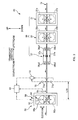
Fig. 2 shows a schematic side view of the thinningapparatus 20 for reducing the thickness of theabsorbent body 1 according to the present embodiment. As described above, thisapparatus 20 reduces the thickness of theabsorbent body 1 to bring the thickness thereof within the target range by sandwiching and pressing theabsorbent body 1 in the thickness direction. - This
apparatus 20 includes a main pressing device 30 (corresponding to pressing device) that reduces the thickenss of theabsorbent bodies absorbent bodies 1a, a pair of up-downrollers pressing device 50 arranged on the downstream side than the mainpressing device 30 along the transport direction, a thickness sensor 70 (corresponding to sensor) that outputs measurement information relating to the thickness of theabsorbent body 1 at a position between the mainpressing device 30 and the auxiliarypressing device 50, and acontroller 90 that sets the size of the gap G50 between the pair of up-downrollers pressing device 50. - And the
controller 90 sets the size of the above gap G50 (hereinafter, also referred as roller gap G50) of the auxiliarypressing device 50 through which the continuous body ofabsorbent bodies 1a is to pass, based on the measurement information relating to the thickness of theabsorbent body 1 output from thethickness sensor 70.
For example, when the thickness indicated by the measurement information is greater than the target range of the thickness of theabsorbent body 1, at the time the targetabsorbent body 1 corresponding to this measurement information passes through the roller gap G50 of the above auxiliarypressing device 50, thecontroller 90 sets the size of the above roller gap G50 so that theabsorbent body 1 is sandwiched and pressed by the pair ofrollers pressing device 50. Thereby, the thickness of theabsorbent body 1 can be brought within the target range. Further, since the thickness of theabsorbent body 1 can be brought within the target range by using the auxiliarypressing device 50 in this way, the mainpressing device 30 on the upstream side need not be finely adjusted and further the number of absorbent articles discarded in association with the adjustment can be reduced. - Hereinafter, description of
configurations Fig. 2 ) is also referred to as the CD direction. By the way, this CD direction is parallel to the width direction of the continuous body ofabsorbent bodies 1a (Fig. 1A ) and further the up-down direction is parallel to the thickness direction of theabsorbent body 1. - In the present embodiment, three different types of
pressing devices pressing device 30. Each of theabsorbent bodies absorbent bodies 1a are sequentially passed through these threepressing devices absorbent bodies 1 is thinned in a stepwise manner and hereby, the ripping of thecarrier sheet 5a is prevented to prevent scattering of pulp fibers inside thelayered body 3 during sandwiching and pressing. - The
pressing device 31 located furthest upstream, being the first step, has a pair of up-downrollers rollers absorbent body 1 toward downstream the transport direction while their outer flat surfaces opposing each other with regard to the CD direction. Accordingly when eachabsorbent body 1 passes through the gap between therollers absorbent body 1 is sandwiched and pressed with the outer circumferential surface of theupper roller 31a and the outer circumferential surface of thelower roller 31b in the thickness direction being in the up-down direction, thereby the thickness of theabsorbent body 1 is reduced. - The center
pressing device 35, being the second step, also has a pair of up-downrollers pressing roller 31 of the first step. However, the outer circumferental surface ofroller 35b being one of the pair ofrollers other roller 35a has formed recessed portions (not shown) of a size slightly larger than the planar form of the layeredbody existing part 1c (Fig. 1A ) at this point. And the depth of this recessed portion is less than the thickness of the layeredbody existing portion 1c at this point. Therefore, when theabsorbent body 1 passes through thispressing device 35, the layeredbody existing portion 1c of theabsorbent body 1 is covered by the recessed portion while being sandwiched and pressed by this ressessed portion and the outer circumferential face of theroller 35b and thereby the thickness of the layeredbody existing portion 1c of theabsorbent body 1, that is, the thickness of theabsorbent body 1 is reduced. Note that, the other configurations besides this are the same as thepressing device 31 of the first step. - The
pressing device 37 located furthest downstream, being at the third step, has a pair of up and downendless belts endless belt absorbent bodies 1 downstream the transport direction while sandwiching and pressing theabsorbent bodies 1 with the belt surfaces opposing each other at this time. Therefore, the thickness of theabsorbent bodies 1 is reduced while being transported. Note that, the circling path of the upperendless belt 37a is formed by thisbelt 37a being wound around a pair of rollers 38a1, 38a2 while the circling path of the lowerendless belt 37b is formed by thisbelt 37b being wound around a pair of rollers 38b1, 38b2, and theendless belts - Note that, in the present embodiment, the three types of
pressing devices pressing device 30, however, the manner in which they are arranged is not limited to such and can be changed accordingly. For example, depending on the circumstance, only one pressing device among the above three may be selected and arranged, two or four or more pressing devices may be seleceted and arranged, or further a plurality of the same type of pressing devices may be combined and arranged. - The auxiliary
pressing device 50 is a so-called auxiliary pressing device that sandwiches and presses theabsorbent body 1 for reducing the thickness thereofto, and allow the thickness of theabsorbent body 1 to fall within the target range when the thickness of theabsorbent body 1 after passing through the mainpressing device 30 exceeds the target thickness range, and has a pair of up-downrollers rollers absorbent bodies 1 downstream along the transport direction with the flat outer surfaces opposing each other with regard to the CD direction. Therefore, when theabsorbent body 1 is thinned, the outer circumferential face of theupper roller 50a and the outer cirucumferential face of thelower roller 50b sandwiches and presses theabsorbent body 1 in the up-down direction being the thickness direction of the absorbent body when theabsorbent body 1 passes through the roller gap G50 which is the gap between therollers - In this example, the position of the
lower roller 50b is fixed by the supportingmember 52 such as an appropriate housing and theupper roller 50a is configured elevatable in the up-down direction being the separating-accessing direction with regard to thislower roller 50b. Therefore, the dimensiton of the above roller gap G50 is changed by elevating and lowering theupper roller 50a. The elevating mechanism that elevates and lowers theupper roller 50a includes, for example, afeed screw mechanism 54 such as a ball screw provided to the above supportingmember 52, and anelevator motor 56 as a drive source for driving thisfeed screw mechanism 54. Here, thefeed screw mechanism 54 converts a rotating movement input thereto to an extending movement in the up-down direction for output. Therefore, theupper roller 50a is made to elevate and descend in accordance to the forward and reverse rotating movement input from theelevator motor 56. - Note that, as the control method for controlling the
elevator motor 56 so that the size of the roller gap G50 falls within the target value (set value), a well known position controlling method (for example, servo controlling and the like) that moves the theupper roller 50a to the position corresponding to the above target value while detecting the position of theupper roller 50a in the up-down direction and the like with a position detector such as a linear encoder can be applied, and explanation thereof is omitted. - Further, the elevating mechanism is not limted to the aforementioned
feed screw mechanism 54 and, for example, a hydraulic cylinder and the like can be applied. And as an example of the hydraulic cylinder in this case, there can be given a hydraulic cylinder and the like equipped with a position detector capable of controlling the extension of the piston based on position control, for example. - The
thickness sensor 70 is positioned between thepressing device 37 at the third step of the mainpressing device 30 and the auxiliarypressing device 50. And the quantity relating to the thickness of theabsorbent bodies 1 after sandwiching and pressing with thepressing device 37 at the third step is measured, and thereafter the measurement information is output to thecontroller 90 for eachabsorbent body 1. - In this example, the
thickness sensor 70 is configured to be capable of directly outputting the thickness of theabsorbent body 1 as a qunatitiy relating to thickness. For example, thethickness sensor 70 includes a pair of upper-lower laser rangefinders amplifier 73. And theupper laser rangefinder 71a measures the distance in the vertical direction between the face projected by the sensor head and the surface of theabsorbent body 1 and thelower laser rangefinder 71b measures the distance in the vertical direction between the face projected by the sensor head and the lower face of theabsorbent body 1, and the measured distance values are sequentially transmitted to theamplifier 73. Each measurement value is respectively subtracted from the measurement value obtained without anabsorbent body 1 to calculate the subtracted values and then adds up the subtracted values. Thereafter, the sum value is output to thecontroller 90 as measurement information of the thickness. - Note that in this example, the
thickness sensor 70 includes theabove amplifier 73 and the measurement value of the thickness of theabsorbent body 1 is output directly from thethickness sensor 70 as measurement information by thisamplifier 73 performing the aforementioned calculation, however, the present invention is not limited to such. For example, thecontroller 90 may be in charge of the function of theamplifier 73 that performs the above calculation. In this case, thethickness sensor 70 would be measuring the distance in the vertical direction between the face projected by the sensor head of theupper laser rangefinder 71a and the surface of theabsorbent body 1, and the distance in the vertical direction between the face projected by the sensor head of thelower laser rangefinder 71b and the lower face of theabsorbent body 1, to output the measured distance values to thecontroller 90 as measurement information relating to thickness. - Further, the
thickness sensor 70 is not limited to theabove laser rangefinders - The
controller 90 controls the elevating movement of theupper roller 50a through controlling theabove elevator motor 56 to set the size of the roller gap G50 of the auxiliarypressing device 50 for eachabsorbent body 1. Thecontroller 90 has an appropriate computer such as a PLC (Prgrammable Logic Computer), for example, and the computer includes a processor and a memory. And the size of the roller gap G50 is set for eachabsorbent body 1 through controlling theabove elevator motor 56 by the processor reading and executing a program stored in the memory. - The size setting of the roller gap G50 is performed based on measurement information (hereinafter also referred as actual thickness information) of the thickness of the
absorbent body 1, sent from thethickness sensor 70. For example, when the thickness indicated by the actual thickness information exceeds the target range (target value plus or minus tolerance) of the thickness of theabsorbent body 1, thecontroller 90 sets the size of the roller gap G50 so that theabsorbent body 1 is sandwiched and pressed when theabsorbent body 1 corresponding to the actual thickness information passes through the roller gap G50. - On the other hand, when the thickness indicated by the actual thickness information is within or smaller than the target thickness range of the thickness of the
absorbent body 1, thecontroller 90 sets the size of roller gap G50 so that theabsorbent body 1 passing through the roller gap G50 is not sandwiched and pressed.
Data for setting as shown in the graph ofFig. 3 , for example, is stored in the memory of thecontroller 90 in advance in order to perform setting in the above manner. In other words, this memory has stored therein data for setting that indicate the relation between the thickness of theabsorbent body 1 at a position between thepressing device 37 at the third step and the auxiliarypressing device 50, and the setting value being the size of the roller gap G50 to be set. Therefore, the processor of thecontroller 90 refers to the data for setting inFig. 3 with actual thickness information of theabsorbent body 1 transmitted from thethickness sensor 70 as the key, and acquires the value for setting the roller gap G50 corresponding to the thickness of this actual thickness information. And the processor controls theaforementioned elevator motor 56 so that the roller gap G50 between the pair of up-downrollers - For example, with the data for setting shown in
Fig. 3 , values among those indicating the thicknesses in the horizontal axis of the graph that are greater than the target range has associated a value set for the roller gap G50 indicated in the vertical axis, that is equal to or smaller than the upper limit value tmax of the target thickness range. Therefore, when the thickness of the actual thickness information exceeds the target range, the auxiliarypressing device 50 certainly sandwiches and presses theabsorbent body 1 thereby defects in the thickness of theabsorbent bodies 1 can be reduced. - Further, for numerical values greater than the target range in the horizontal axis of
Fig. 3 , a relation is defined such that the setting value of the roller gap G50 gradually decreases as the thickness in the horizontal axis increases. Therefore, the thickness of theabsorbent body 1 after sandwiching and pressing with the auxiliarypressing device 50 can be further certainly brought within the target range, and as a result, thickness defects of theabsorbent body 1 can be further reduced. - On the other hand, for numerical values, among the values in the horizontal axis of the graph in
Fig. 3 that are within or smaller than the target range has associated, a value set for the roller gap G50 indicated in the vertical axis that is equal to the upper limit value tmax of the target thickness range. Therefore, when the thickness of the actual thickness information is within the target range, theabsorbent body 1 only passes through the roller gap G50 of the auxiliarypressing device 50 without the auxiliarypressing device 50 performing sandwiching and pressing, and consequently thickness defects associated with the auxiliarypressing device 50 can be prevented from occurring. However, for numerical values within or smaller than the target range, it is preferable that the setting value of the roller gap G50 is associated with a value tb larger than the maximum value tmax of the target range, as shown with the chain double-dashed line ofFig. 3 . In this way, theabsorbent body 1 is in a completely non-conatact state with theupper roller 50a so that sandwiching and pressing with the auxiliarypressing device 50 can be perfectly prevented. - Further, when the relation of the data for setting in
Fig. 3 is variable in accordance with the transport speed of theabsorbent body 1, the assumed transport speed of theabsorbent body 1 during manufacturing may be divided into a plurality of sections with the above data for setting for each section stored in the memory. Note that in this case, a corresponding data for setting is selected based on the actual value of the transport speed of the absorbent body 1 (for example, the transport speed of theabsorbent body 1 at the roller gap G50), and the setting value of the roller gap G50 of the auxiliarypressing device 50 is acquired based on the selected data for setting. By the way, the reason why the relation of the graph shown inFig. 3 may vary according to the transport speed is that since the time during which the sandwiching and pressing with the auxiliarypressing device 50 is performed differs with differing in transport speed, there is fear that the effect in crushing in the thickness direction of theabsorbent body 1 would differ even when the size of the roller gap G50 is the same. - Such data for setting may be stored in the memory of the
controller 90 in a format of an arithmetic expression, or may be stored in a setting table format with the thickness of theabsorbent body 1 and the setting value for the roller gap G50 in a corresponding state, or further in a state besides the above. - By the way, the continuous body of
absorbent bodies 1a according to the present embodiment is configured with a plurality ofabsorbent bodies Fig. 1A ). Further, thethickness sensor 70 outputs actual thickness information for eachabsorbent body 1 and the auxiliarypressing device 50 sets the size of the roller gap G50 for eachabsorbent body 1 based on the actual thickness information. Further, thethickness sensor 70 is positioned at a location upstream along the transport direction distant from the auxiliarypressing device 50 by a predetermined distance (Fig. 2 ).
Therefore, the size setting of the above roller gap G50 needs to be performed while associating the actual thicknes information for eachabsorbent body 1. And this association is performed, for example, in the following manner. - First, the actual thickness information is recorded in the memory of the
controller 90 immediately after each output from thethickness sensor 70. Further, each recorded actual thickness information has recorded in association therewith a count value having a predetermined initial value. This predetermined value is, for example, the number ofabsorbent bodies pressing device 50 and the measuring position of thethickness sensor 70. Further, there is positioned proximate the auxiliarypressing device 50, apassage detecting sensor 95 such as a phototube and the like that outputs at real time a detection signal whenever detecting the tail end (upstream end) of the layeredbody existing part 1c of eachabsorbent body 1. And the position where detection is made by thepassage detecting sensor 95 is set at a position distant, from the center position of the auxiliarypressing device 50, on the upstream side (or the downstream side) by a distance that is equal to an integer multiple (equal to or greater than an integer multiple of two) of the entire length of theabsorbent body 1. Note that, substitutional detection is performed by thispassage detecting sensor 95 to detect the tail end (upstream end) of the layeredbody existing part 1c of theabsorbent body 1 passing through the roller gap G50 of the auxiliarypressing device 50, by setting the entire length to equal an integer multiple. - And the aforementioned count value is subtracted every time the above detection signal is output and when this count value reaches one, the processor of the
controller 90 reads from the memory the actual thickness information that takes this count value of one, and sets the size of the roller gap G50 based on this actual thickness information and the aforementioned data for setting. Hereby, the roller gap G50 is set while associating actual thickness information with eachabsorbent body 1. - Further, the size setting of the roller gap G50 is, for example, performed while the layered body
non-existing part 1e of theabsorbent body 1 passes through the roller gap G50. That is, the size setting of the roller gap G50 for theabsorbent body 1 in subject of setting is performed while the layered bodynon-existing part 1e of theabsorbent body 1 adjacent on the downstream side to theabsorbent body 1 in subject to setting, and the layered bodynon-existing part 1e of the subsequentabsorbent body 1 in subject to setting are passing through the roller gap G50. Thereby, the size setting of the roller gap G50 can be certainly completed before the layeredbody existing part 1c of theabsorbent body 1 in subject to setting arrives. - And the size of the roller gap G50 that is set, is maintained at a fixed value until the same the layered
body existing part 1c completely passes through the roller gap G50. In other words, a setting value is given to eachabsorbent body 1 as a fixed value. Therefore, at this setting, with the actual thickness information of theabsorbent body 1 in subject to setting, the processor of thecontroller 90 calculates the average actual thickness value by averaging the thickness of the the layeredbody existing part 1c along the entire length thereof, refers to the data for setting in aforementionedFig. 3 with the average value as the representative value of the actual thickness, and acquires the value set for the roller gap G50 corresponding to this representative value. And the processor of thecontroller 90 controls theelevator motor 56 with this single setting value until the the layeredbody existing part 1c completely passes through. However, the representative value of the actual thickness is not limited to the aforementioned average value and, for example, the actual thickness of the the layeredbody existing part 1c at a point such as that at the center of the plane can be used. - While the present invention has been described in conjunction with the embodiments, it should be understood that the present invention is not limited to the above embodiments and can be changed as in the following.
- Although the surface of the
layered body 3 of the carrier sheet 5 (5a) having the end portions in the width direction of the carrier sheet 5 (5a) covered was shown as an example of theabsorbent body 1 in the aforementioned embodiment, the present invention is not limited to such. For example, a carrier sheet 5 (5a) with the end portions in the width direction left in an extended state (seeFig. 1B ) without thelayered body 3 covered at the ends may be used as theabsorbent body 1. Further, the carrier sheet 5 (5a) in such state (Fig. 1B ) being covered by a separate liquide permeable sheet from above (not shown) to form a three layer structure with thelayered body 3 sandwiched by the liquid permeable sheet and the carrier sheet 5 (5a) can be made theabsorbent body 1. - Although the setting value of the roller gap G50 was acquired as a single fixed value for each
absorbent body 1 and thereby maintained the size of the roller gap G50 constant along the entire length of the the layeredbody existing part 1c of theabsorbent body 1, in the aforementioned embodiment, the present invention is not limited to such.
For example, when the aforementioned actual thickness information has respective thickness values that are associated with the positions in the transport direction defined on theabsorbent body 1, setting values corresponding to the thicknesses of the positions may be acquired from the data for setting inFig. 3 , to change the size of the roller gap G50 using the setting value corresponding to each position in synchronization with the passage of each position through the roller gap G50. Note that, the generation of the actual thickness information as that above is made by, for example, acquiring data of the above positions by an output signal from a rotary encoder that makes a single rotation for an amount of transport for a singleabsorbent body 1, and recording into the memory of thecontroller 90 the thickness value that is output from the thickness sensor, in association with the position data, simultaneously with the acquiring of data of the positions. Further, each position detection of theabsorbent body 1 passing through the roller gap G50 is, for example, performed based on the output signal from the rotary encoder rotating in synchronization with theroller 50a (or 50b) of the auxiliarypressing device 50, and the same processor sequentially acquires from the above actual thickness information, the thickness value corresponding to the position indicated by this output signal. Then, the setting value corresponding to the thickness value is obtained by referring to the data for setting inFig. 3 , and thereafter the size of the roller gap G50 is sequentially set. - A sensor for measuring the thickness of the
absorbent body 1 was not set on the downstream side of the auxiliarypressing device 50 in the aforementioned embodiment, however, a sensor may be provided to the position on the downstream side of the auxiliarypressing device 50 to measure with this sensor the thickness of theabsorbent body 1 after passing through the auxiliarypressing device 50. In this case, the sensor can have, for example, applied thereto a configuration same as that with theaforementioned thickness sensor 70 provided at the upstream side of the auxiliarypressing device 50. And the measurement information is, for example, sequentially transmitted to thecontroller 90 where thecontroller 90 compares the measurement information with the thickness target range to, for example, output an alarm when the thickness is outside the target, which is used to identify thickness defects. -
- 1
- absorbent body, 1a continuous body of absorbent bodies,
- 1c
- layered body existing part, 1e layered body non-existing part,
- 3
- layered body,
- 5
- liquid permeable sheet, 5a carrier sheet,
- 10
- fiber stacking device, 12 folding guide member,
- 20
- thinning apparatus for reducing the thickness of absorbent body,
- 30
- main pressing device (pressing device),
- 31
- first step pressing device, 31a roller, 31b roller,
- 35
- second step pressing device, 35a roller, 35b roller,
- 37
- third step pressing device, 37a endless belt, 37b endless belt,
- 38a1
- roller, 38a2 roller, 38b1 roller, 38b2 roller,
- 50
- auxiliary pressing device, 50a roller, 50b roller, 52 supporting member,
- 54
- elevating mechanism, 56 elevator motor,
- 70
- thickness sensor (sensor), 71a laser rangefinder, 71b laser rangefinder,
- 73
- amplifier,
- 90
- controller, 95 passage detecting sensor,
- G50
- roller gap (gap)
Claims (5)
- An apparatus for reducing a thickness of an absorbent body having liquid absorbent fiber as a main material, comprising:a pressing device that reduces the thickness of the absorbent body transported in a transport direction, by sandwiching and pressing the absorbent body in a thickness direction orthogonal to the transport direction;a pair of rollers that is positioned on a downstream side along the transport direction than the pressing device, and rotates while passing the absorbent body through a gap formed by outer circumferences of the pair of rollers opposing each other;a sensor that outputs measurement information relating to the thickness of the absorbent body at a position between the pressing device and the pair of rollers; anda controller that sets a size of the gap between the pair of rollers based on the measurement information.
- The apparatus for reducing a thickness of an absorbent body according to claim 1, wherein
the controller sets the size of the gap in such a manner that the absorbent body that passes through the gap is sandwiched and pressed by the pair of rollers, when a thickness indicated by the measurement information is greater than a target range of the thickness of the absorbent body. - The apparatus for reducing a thickness of an absorbent body according to claim 1 or claim 2, wherein
the controller sets the size of the gap in such a manner that the absorbent body that passes through the gap is not sandwiched nor pressed by the pair of rollers, when a thickness indicated by the measurement information is equal to or within a target range of the thickness of the absorbent body. - The apparatus for reducing a thickness of an absorbent body according to any one of claims 1 through 3, wherein
a plurality of the absorbent bodies are transported in line in the transport direction,
the sensor outputs the measurement information for each of the absorbent bodies, and
the controller sets the size of the gap of the pair of rollers for each of the absorbent bodies while associating the measurement information to each of the absorbent bodies. - A method for reducing a thickness of an absorbent body having liquid absorbent fiber as a main material, comprising:reducing a thickness of the absorbent body transported in a transport direction, by sandwiching and pressing the absorbent body in a thickness direction orthogonal to the transport direction;passing the absorbent body through a gap between a pair of rollers that are positioned on a downstream side along the transport direction than the pressing device, and that have outer circumferences of the pair of rollers opposing each other;outputting by a sensor, measurement information relating to the thickness of the absorbent body at a position between the pressing device and the pair of rollers; andsetting a size of the gap based on the measurement information when the absorbent body is passed through the gap between the pair of rollers.
Applications Claiming Priority (2)
| Application Number | Priority Date | Filing Date | Title |
|---|---|---|---|
| JP2011010063A JP5677865B2 (en) | 2011-01-20 | 2011-01-20 | Apparatus and method for reducing absorber thickness |
| PCT/JP2012/050589 WO2012099015A1 (en) | 2011-01-20 | 2012-01-13 | Device and method for reducing thickness of absorber |
Publications (1)
| Publication Number | Publication Date |
|---|---|
| EP2666447A1 true EP2666447A1 (en) | 2013-11-27 |
Family
ID=46515643
Family Applications (1)
| Application Number | Title | Priority Date | Filing Date |
|---|---|---|---|
| EP12736912.2A Withdrawn EP2666447A1 (en) | 2011-01-20 | 2012-01-13 | Device and method for reducing thickness of absorber |
Country Status (6)
| Country | Link |
|---|---|
| US (1) | US9272478B2 (en) |
| EP (1) | EP2666447A1 (en) |
| JP (1) | JP5677865B2 (en) |
| CN (1) | CN103327943B (en) |
| BR (1) | BR112013017924A2 (en) |
| WO (1) | WO2012099015A1 (en) |
Cited By (2)
| Publication number | Priority date | Publication date | Assignee | Title |
|---|---|---|---|---|
| CN105643970A (en) * | 2015-12-21 | 2016-06-08 | 杭州珂瑞特机械制造有限公司 | Special magic hook reinforcing device for diaper production line and reinforcing method |
| CN108175575A (en) * | 2018-01-29 | 2018-06-19 | 广东鑫雁科技有限公司 | A kind of amenities core set composite |
Families Citing this family (7)
| Publication number | Priority date | Publication date | Assignee | Title |
|---|---|---|---|---|
| SG11201408751QA (en) | 2012-06-29 | 2015-01-29 | Kuraray Co | Method for producing (meth)acrylic resin composition |
| JP5946817B2 (en) * | 2013-12-18 | 2016-07-06 | 花王株式会社 | Absorber manufacturing method |
| JP6994316B2 (en) * | 2017-07-25 | 2022-01-14 | 花王株式会社 | Manufacturing method of absorbent articles |
| JP7027103B2 (en) * | 2017-10-03 | 2022-03-01 | 花王株式会社 | Absorber manufacturing method and absorber manufacturing equipment |
| DE112017007446T5 (en) * | 2017-10-03 | 2020-08-06 | Kao Corp. | METHOD FOR PRODUCING AN ABSORBENT ARTICLE |
| IT201700123038A1 (en) * | 2017-10-30 | 2019-04-30 | Gdm Spa | APPARATUS AND METHOD OF FORMING AN ABSORBENT PADDING |
| JP7106242B1 (en) * | 2022-04-19 | 2022-07-26 | 株式会社日本製鋼所 | Laminate molding system control method and laminate molding system |
Family Cites Families (9)
| Publication number | Priority date | Publication date | Assignee | Title |
|---|---|---|---|---|
| US3648496A (en) * | 1969-06-16 | 1972-03-14 | Marotta Valve Corp | Apparatus for controlling rolling mill |
| JPS5666315A (en) * | 1979-10-31 | 1981-06-04 | Sumitomo Metal Ind Ltd | Controlling method for sheet thickness in strip mill |
| US4768433A (en) * | 1985-01-25 | 1988-09-06 | Measurex Corporation | Hot air calender roll controller |
| JP3519094B2 (en) * | 1993-01-11 | 2004-04-12 | 花王株式会社 | Method and apparatus for manufacturing absorber |
| JP3719817B2 (en) * | 1997-05-26 | 2005-11-24 | 花王株式会社 | Absorbent article manufacturing method and manufacturing apparatus thereof |
| JP3868628B2 (en) * | 1998-06-25 | 2007-01-17 | 花王株式会社 | Absorbent articles |
| JP4297715B2 (en) * | 2003-03-31 | 2009-07-15 | ユニ・チャーム株式会社 | SEALING DEVICE AND SEALING METHOD USING THE SEALING DEVICE |
| JP4592690B2 (en) | 2004-04-30 | 2010-12-01 | 株式会社瑞光 | Welding equipment |
| CN100475498C (en) * | 2004-04-30 | 2009-04-08 | 株式会社瑞光 | Melt-bonding device |
-
2011
- 2011-01-20 JP JP2011010063A patent/JP5677865B2/en not_active Expired - Fee Related
-
2012
- 2012-01-13 WO PCT/JP2012/050589 patent/WO2012099015A1/en not_active Ceased
- 2012-01-13 US US13/980,395 patent/US9272478B2/en active Active
- 2012-01-13 CN CN201280005823.2A patent/CN103327943B/en not_active Expired - Fee Related
- 2012-01-13 BR BR112013017924A patent/BR112013017924A2/en not_active Application Discontinuation
- 2012-01-13 EP EP12736912.2A patent/EP2666447A1/en not_active Withdrawn
Non-Patent Citations (1)
| Title |
|---|
| See references of WO2012099015A1 * |
Cited By (2)
| Publication number | Priority date | Publication date | Assignee | Title |
|---|---|---|---|---|
| CN105643970A (en) * | 2015-12-21 | 2016-06-08 | 杭州珂瑞特机械制造有限公司 | Special magic hook reinforcing device for diaper production line and reinforcing method |
| CN108175575A (en) * | 2018-01-29 | 2018-06-19 | 广东鑫雁科技有限公司 | A kind of amenities core set composite |
Also Published As
| Publication number | Publication date |
|---|---|
| CN103327943B (en) | 2015-12-02 |
| US20140182462A1 (en) | 2014-07-03 |
| CN103327943A (en) | 2013-09-25 |
| JP2012147997A (en) | 2012-08-09 |
| BR112013017924A2 (en) | 2016-10-11 |
| US9272478B2 (en) | 2016-03-01 |
| WO2012099015A1 (en) | 2012-07-26 |
| JP5677865B2 (en) | 2015-02-25 |
Similar Documents
| Publication | Publication Date | Title |
|---|---|---|
| US9272478B2 (en) | Apparatus for reducing the thickness of an absorbent body and method of the same | |
| US8863803B2 (en) | Apparatus for manufacturing absorbent article | |
| US9284150B2 (en) | Meandering correction apparatus of a continuous sheet associated with an absorbent article | |
| EP1551742B1 (en) | Web velocity-based registration control system | |
| WO2011118493A1 (en) | Defective workpiece discharging device | |
| KR101533139B1 (en) | Device and method for manufacturing absorptive articles | |
| JP5986842B2 (en) | Manufacturing apparatus and manufacturing method for linked product of individually packaged products related to absorbent article | |
| JP2022505112A (en) | Winding equipment and methods equipped with an evaluation system for the web material to be processed | |
| CN105189059B (en) | Method and apparatus for measuring the protrusion length of a protrusion | |
| CN109069303A (en) | Method and apparatus for manufacturing flat member relevant to absorbent commodity | |
| JP2018092625A (en) | Production line control system | |
| JP2007152689A (en) | Corrugating machine and production control device used therein | |
| WO2015110517A1 (en) | Device and method for measuring the thickness of a moving web material | |
| EP3473219A1 (en) | Method and device for manufacturing sheet member for absorbent article | |
| CN107920927B (en) | Method and apparatus for making sheet-like members associated with absorbent articles | |
| FI129921B (en) | Apparatus, arrangement and method of measuring rolls of fibrous web material | |
| KR20200109021A (en) | Manufacturing Device of Defecation Pad | |
| EP4525799B1 (en) | Method and apparatus for automated gap control of a scarfing roll | |
| CN223558609U (en) | A device for detecting the flatness of battery aluminum foil in a slitting machine. | |
| CN203405191U (en) | Large precise thin plate thickness contact measuring streamline apparatus | |
| JP2013003117A (en) | Thickness measuring method of sheet-like material, and conveyance device of sheet-like material | |
| BR112021007208B1 (en) | MACHINE FOR WINDING A BLANKET MATERIAL INTO A PLURALITY OF SECONDARY COILS AND METHOD FOR WINDING A BLANKET MATERIAL |
Legal Events
| Date | Code | Title | Description |
|---|---|---|---|
| PUAI | Public reference made under article 153(3) epc to a published international application that has entered the european phase |
Free format text: ORIGINAL CODE: 0009012 |
|
| 17P | Request for examination filed |
Effective date: 20130711 |
|
| AK | Designated contracting states |
Kind code of ref document: A1 Designated state(s): AL AT BE BG CH CY CZ DE DK EE ES FI FR GB GR HR HU IE IS IT LI LT LU LV MC MK MT NL NO PL PT RO RS SE SI SK SM TR |
|
| DAX | Request for extension of the european patent (deleted) | ||
| STAA | Information on the status of an ep patent application or granted ep patent |
Free format text: STATUS: THE APPLICATION IS DEEMED TO BE WITHDRAWN |
|
| 18D | Application deemed to be withdrawn |
Effective date: 20140801 |