EP2665976B1 - Piping communication system - Google Patents
Piping communication system Download PDFInfo
- Publication number
- EP2665976B1 EP2665976B1 EP12736455.2A EP12736455A EP2665976B1 EP 2665976 B1 EP2665976 B1 EP 2665976B1 EP 12736455 A EP12736455 A EP 12736455A EP 2665976 B1 EP2665976 B1 EP 2665976B1
- Authority
- EP
- European Patent Office
- Prior art keywords
- piping
- unit case
- unit
- outdoor
- indoor
- Prior art date
- Legal status (The legal status is an assumption and is not a legal conclusion. Google has not performed a legal analysis and makes no representation as to the accuracy of the status listed.)
- Not-in-force
Links
- 238000004891 communication Methods 0.000 title claims description 21
- 239000003507 refrigerant Substances 0.000 claims description 36
- 230000008054 signal transmission Effects 0.000 claims description 20
- 239000000463 material Substances 0.000 claims description 2
- 239000007788 liquid Substances 0.000 description 29
- 230000005540 biological transmission Effects 0.000 description 5
- 238000000034 method Methods 0.000 description 5
- 230000000694 effects Effects 0.000 description 3
- 238000010586 diagram Methods 0.000 description 2
- 239000004020 conductor Substances 0.000 description 1
- 238000001514 detection method Methods 0.000 description 1
- 230000005389 magnetism Effects 0.000 description 1
- 239000000615 nonconductor Substances 0.000 description 1
- 230000035699 permeability Effects 0.000 description 1
- 230000000452 restraining effect Effects 0.000 description 1
- 238000004804 winding Methods 0.000 description 1
Images

Classifications
-
- F—MECHANICAL ENGINEERING; LIGHTING; HEATING; WEAPONS; BLASTING
- F24—HEATING; RANGES; VENTILATING
- F24F—AIR-CONDITIONING; AIR-HUMIDIFICATION; VENTILATION; USE OF AIR CURRENTS FOR SCREENING
- F24F1/00—Room units for air-conditioning, e.g. separate or self-contained units or units receiving primary air from a central station
- F24F1/06—Separate outdoor units, e.g. outdoor unit to be linked to a separate room comprising a compressor and a heat exchanger
- F24F1/26—Refrigerant piping
-
- F—MECHANICAL ENGINEERING; LIGHTING; HEATING; WEAPONS; BLASTING
- F24—HEATING; RANGES; VENTILATING
- F24F—AIR-CONDITIONING; AIR-HUMIDIFICATION; VENTILATION; USE OF AIR CURRENTS FOR SCREENING
- F24F1/00—Room units for air-conditioning, e.g. separate or self-contained units or units receiving primary air from a central station
- F24F1/06—Separate outdoor units, e.g. outdoor unit to be linked to a separate room comprising a compressor and a heat exchanger
- F24F1/26—Refrigerant piping
- F24F1/32—Refrigerant piping for connecting the separate outdoor units to indoor units
-
- F—MECHANICAL ENGINEERING; LIGHTING; HEATING; WEAPONS; BLASTING
- F24—HEATING; RANGES; VENTILATING
- F24F—AIR-CONDITIONING; AIR-HUMIDIFICATION; VENTILATION; USE OF AIR CURRENTS FOR SCREENING
- F24F1/00—Room units for air-conditioning, e.g. separate or self-contained units or units receiving primary air from a central station
- F24F1/06—Separate outdoor units, e.g. outdoor unit to be linked to a separate room comprising a compressor and a heat exchanger
- F24F1/40—Vibration or noise prevention at outdoor units
-
- F—MECHANICAL ENGINEERING; LIGHTING; HEATING; WEAPONS; BLASTING
- F24—HEATING; RANGES; VENTILATING
- F24F—AIR-CONDITIONING; AIR-HUMIDIFICATION; VENTILATION; USE OF AIR CURRENTS FOR SCREENING
- F24F13/00—Details common to, or for air-conditioning, air-humidification, ventilation or use of air currents for screening
- F24F13/20—Casings or covers
-
- F—MECHANICAL ENGINEERING; LIGHTING; HEATING; WEAPONS; BLASTING
- F28—HEAT EXCHANGE IN GENERAL
- F28F—DETAILS OF HEAT-EXCHANGE AND HEAT-TRANSFER APPARATUS, OF GENERAL APPLICATION
- F28F27/00—Control arrangements or safety devices specially adapted for heat-exchange or heat-transfer apparatus
-
- F—MECHANICAL ENGINEERING; LIGHTING; HEATING; WEAPONS; BLASTING
- F24—HEATING; RANGES; VENTILATING
- F24F—AIR-CONDITIONING; AIR-HUMIDIFICATION; VENTILATION; USE OF AIR CURRENTS FOR SCREENING
- F24F13/00—Details common to, or for air-conditioning, air-humidification, ventilation or use of air currents for screening
- F24F13/20—Casings or covers
- F24F2013/207—Casings or covers with control knobs; Mounting controlling members or control units therein
Definitions
- the present invention relates to a piping communication system and, more particularly, to a piping communication system in which a signal transmission unit is installed within an outdoor unit or an indoor unit.
- an air-conditioner is divided into an indoor unit and an outdoor unit, and the indoor unit and the outdoor unit are electrically connected to transfer an electrical signal.
- the indoor unit and the outdoor unit are electrically connected to transfer an electrical signal.
- a technique of transmitting and receiving an electrical signal by using a refrigerant piping connecting a plurality of indoor units and a smaller number of outdoor units than that of the indoor units has been introduced.
- a gas refrigerant piping referred to as a gas piping , hereinafter
- a liquid refrigerant piping referred to as a liquid piping , hereinafter
- a signal transmission unit is installed at the refrigerant piping and a signal line of the signal transmission unit electrically connects the respective control boards and the refrigerating piping.
- the signal transmission unit may be installed at an outer side of an outdoor unit case or an indoor unit case, and according to circumstances, the signal transmission unit is installed within the outdoor unit case or the indoor unit case and the assembling state may be desirably maintained.
- JP H06 2880 A discloses a separate type air conditioner in which an electrical insulator is provided respectively on an indoor unit side and an outdoor unit side of a gas side refrigerant pipe and a liquid side refrigerant pipe.
- the signal transmission unit in case in which the signal transmission unit is installed within the outdoor unit case or the indoor unit case, when the refrigerant piping vibrates, the signal transmission unit may be brought into contact with a neighboring different conductor to cause a short.
- an object of the present invention is to provide a piping communication system capable of restraining a refrigerant piping from vibrating to thus prevent a signal transmission unit coupled to the refrigerating piping from being shorted.
- a piping communication system including: a refrigerant piping connecting an outdoor heat exchanger and an indoor heat exchanger through an outdoor unit case and an indoor unit case; a signal transmission unit electrically connected to the refrigerant piping to transfer a signal transmitted or received through the refrigerant piping to a microcomputer; and a vibration preventing member installed between the outdoor unit case or the indoor unit case and the refrigerant piping to support the refrigerant piping with respect to the outdoor unit case or the indoor unit case, wherein the short-circuit preventing member comprises: a support unit allowing the refrigerant piping to be inserted therethrough and supported; and a fixed unit formed to extend from an outer circumferential surface of the support unit and fixed to the outdoor unit case, wherein at least one side of the support unit is protruded than one side of the fixed unit and inserted into a piping hole provided in the outdoor unit case or the indoor unit case; and wherein the fixed unit comprises a through hole and is configured to
- the vibration preventing member covering the refrigerant piping is provided between the outdoor unit case or the indoor unit case and the refrigerant piping, although vibration is transferred to the refrigerant piping, the vibration is absorbed or suppressed by the vibration preventing member fixed to the outdoor unit case or the indoor unit case, thus reducing the amplitude of the refrigerant piping, whereby although the signal transmission unit is installed within the outdoor unit case of the indoor unit case, the signal transmission unit can be prevented from being brought into contact with neighboring components and shorted.
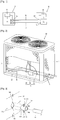
- FIG. 1 is a distribution diagram of an air-conditioner having a piping communication system according to an embodiment of the present invention.
- FIG. 2 is a perspective view showing an assembling state of a refrigerant piping and an outdoor unit case when a signal transmission unit is installed within an outdoor unit in the air-conditioner according to FIG. 1 .
- an indoor unit 10 and an outdoor unit 20 are disposed with an outer wall of a building interposed therebetween and connected such that an electrical signal is transmitted and received between the outdoor unit 10 and the indoor unit 20 through a liquid piping 40 or a gas piping 30.
- An outdoor heat exchanger 11 of the outdoor unit 10 and an indoor heat exchanger 21 of the indoor unit 20 are connected to both ends of the gas piping 30 and the liquid piping 40, and an outdoor signal transmission unit 13 and an indoor signal transmission unit 23 are installed between the outdoor heat exchanger 11 and the indoor heat exchanger 21 in order to transfer a transferred electric signal to the outdoor control unit 12 of the outdoor unit 10 and the indoor control unit 22 of the indoor unit 20.
- the outdoor signal transmission unit 13 (here, the outdoor signal transmission unit and the indoor signal transmission unit have the same configuration, so, hereinafter, the outdoor signal transmission unit will be described as a representative example) includes a core assembly 50 coupled to the refrigerant piping 40 (here, the refrigerant piping may correspond to a gas piping or a liquid piping, and hereinafter, a liquid piping will be described) and making impedance with respect to an AC electrical signal, and a plurality of signal terminals 61 and 62 separated from the core assembly 50 and coupled to the liquid piping 40 and electrically connecting the liquid piping 40 and the outdoor control unit 12.
- a pair of cores generally formed to have a hemispherical section are accommodated in a core holder and coupled to cover up the liquid piping 40.
- the core assembly 50 has magnetism to make inductance corresponding to one time of winding and is coupled to cover up the gas piping 30 or the liquid piping 40.
- the AC signal when an AC signal flows through the refrigerant pipings 30 and 40 installed between the outdoor unit 10 and the indoor unit 20, the AC signal has attenuation characteristics according to a distance by the transmission line impedance Z 0 of the pipings themselves.
- the impedance Z 0 of the transmission line is proportional to the distance, and the signal strength of the AC signal used for detecting the distance of the refrigerant pipings 30 and 40 is reduced by the transmission line impedance Z 0 and the core.
- the impedance value of the core and the strength of the AC control signal of the transmitter and the receiver are known, inversely, the distance information can be known.
- the refrigerant pipings may be used as a transmission path of a distance detection signal, whereby a piping distance between the outdoor unit and the indoor unit used for calculating an amount of a refrigerant can be automatically calculated.
- the refrigerant pipings 30 and 40 are connected to the outdoor heat exchanger 11 through an outdoor unit case 14 (the indoor unit case is the same and, here, the outdoor unit case will be described as an example), and the core assembly 50 and the signal terminals 61 and 62 may be installed outside the outdoor unit case 14 or may be installed within the outdoor unit case 14.
- the liquid piping 40 When the core assembly 50 and the signal terminals 61 and 62 are installed outside the outdoor unit case 14, although the liquid piping 40 is slightly shaken by a surrounding environment, it does not generate a short with components in the vicinity of the outdoor unit 10, but when the door assembly 50 and the signal terminals 61 and 62 are installed within the outdoor unit case 14, when the liquid piping 40 vibrates, the liquid piping 40 comes into contact with the neighboring components to generate a short.
- FIG. 3 is an enlarged view of a portion A in FIG. 2 and exploded perspective view of a vibration preventing member.
- FIG. 4 is a vertical sectional view showing an embodiment of a method for assembling a vibration preventing member according to FIG. 3 .
- FIG. 5 is a vertical sectional view showing another embodiment of a method for assembling a vibration preventing member according to FIG. 3 .
- a vibration preventing member 100 is provided between the refrigerant piping 40 (hereinafter, the liquid piping will be described as an example) and the outdoor unit case or the indoor unit case 14 (hereinafter, the outdoor unit case will be described as an example) and coupled to support the liquid piping 40 with respect to the outdoor unit case 11.
- the vibration preventing member 100 may include a support unit 110 in which the liquid piping 40 is insertedly supported and a fixed unit 120 formed to extend from an outer circumferential surface of the support unit 110 and fixed to the outdoor unit case 14.
- the vibration preventing member 100 is made of a material having an elastic modulus greater than that of the outdoor unit case 14.
- the support unit 110 is formed to have a cylindrical shape having a predetermined length, namely, a length which is longer than the thickness of the outdoor unit case 14 and protruded than one side of the fixing unit 110, and inserted into a piping hole 14a of the outdoor unit case 14.
- the outer circumferential surface of the support unit 110 may not necessarily have the circular shape but may be formed to have a quadrangular shape or any other shapes.
- the support unit 110 may have the cylindrical shape as shown in FIG. 3 , or according to circumstances, the support unit 110 may be formed to have a cutout face 111 as shown in FIG. 6 .
- the support unit 110 when the support unit 110 has the cutout face 111, when the vibration preventing member 100 is coupled to the liquid piping 40, the support unit 110 can be open to both sides to insert the liquid piping 40 in a radial direction.
- the vibration preventing member 100 can be coupled even in a state in which the core assembly is already assembled or the liquid piping is already connected.
- the fixed unit 120 may be formed to be protruded from both sides or protruded from only one side, and three or more fixed units 120 may be formed.
- the fixed unit 120 may be formed to be protruded from the entire outer circumferential surface of the support unit 110 in an annular manner.
- the fixed units 120 include either a through hole 121, respectively, and are screw-fastened to a fastening hole 14b provided on the outdoor unit case 14 or, as shown in FIG. 5 , the fixed unit 120 has a hook projection 122 and is hook-coupled in a hook hole 14c provided in the outdoor unit case 14.
- the piping communication system according to the present invention as described above has the following operational effects.
- the vibration preventing member 100 is installed between the piping hole 14a of the outdoor unit case 14 and the liquid piping 40 inserted into the piping hole 14a.
- the vibration preventing member 100 includes the support unit 110 in which the liquid piping 40 is inserted and the fixed unit 120 fixed to the outdoor unit case 14 in order to support the liquid piping 40.
- the vibration is absorbed or suppressed by the vibration preventing member 100 fixed to the outdoor unit case 14, thus reducing amplitude of the liquid piping 40.
- the core assembly and the signal terminals are coupled to be positioned within the outdoor unit case 14, the core assembly and the signal terminals can be prevented from being in contact with neighboring outdoor unit components, thereby preventing the piping communication system from being shorted.
- the vibration preventing member is installed between the outdoor unit case and the liquid piping
- the vibration preventing member may also be installed between the indoor unit case and the liquid piping, between the outdoor unit case and the gas piping, or between the indoor unit case and the gas piping.
- the basic configuration and operational effect are similar to those of the foregoing embodiment.
Landscapes
- Engineering & Computer Science (AREA)
- Mechanical Engineering (AREA)
- General Engineering & Computer Science (AREA)
- Chemical & Material Sciences (AREA)
- Combustion & Propulsion (AREA)
- Physics & Mathematics (AREA)
- Thermal Sciences (AREA)
- Pipe Accessories (AREA)
- Air Conditioning Control Device (AREA)
- Other Air-Conditioning Systems (AREA)
Description
- The present invention relates to a piping communication system and, more particularly, to a piping communication system in which a signal transmission unit is installed within an outdoor unit or an indoor unit.
- In general, an air-conditioner is divided into an indoor unit and an outdoor unit, and the indoor unit and the outdoor unit are electrically connected to transfer an electrical signal. However, when a plurality of indoor units are connected in parallel to a single outdoor unit or when a refrigerant piping is installed within a wall body of a building and a plurality of indoor units are connected in parallel to the refrigerant piping, it is difficult to electrically connect the respective indoor units to a smaller number of outdoor units in many cases.
- Thus, a technique of transmitting and receiving an electrical signal by using a refrigerant piping connecting a plurality of indoor units and a smaller number of outdoor units than that of the indoor units has been introduced. For example, a gas refrigerant piping (referred to as a gas piping , hereinafter) and a liquid refrigerant piping (referred to as a liquid piping , hereinafter) are electrically connected to a control board of an outdoor unit and a control board of an indoor unit, respectively, so as to be used as communication mediums for transferring a control signal between the indoor units and the outdoor unit. To this end, a signal transmission unit is installed at the refrigerant piping and a signal line of the signal transmission unit electrically connects the respective control boards and the refrigerating piping.
- The signal transmission unit may be installed at an outer side of an outdoor unit case or an indoor unit case, and according to circumstances, the signal transmission unit is installed within the outdoor unit case or the indoor unit case and the assembling state may be desirably maintained.
-
JP H06 2880 A - However, in the related art piping communication system, in case in which the signal transmission unit is installed within the outdoor unit case or the indoor unit case, when the refrigerant piping vibrates, the signal transmission unit may be brought into contact with a neighboring different conductor to cause a short.
- Therefore, an object of the present invention is to provide a piping communication system capable of restraining a refrigerant piping from vibrating to thus prevent a signal transmission unit coupled to the refrigerating piping from being shorted.
- In order to achieve the above object, there is provided a piping communication system including: a refrigerant piping connecting an outdoor heat exchanger and an indoor heat exchanger through an outdoor unit case and an indoor unit case; a signal transmission unit electrically connected to the refrigerant piping to transfer a signal transmitted or received through the refrigerant piping to a microcomputer; and a vibration preventing member installed between the outdoor unit case or the indoor unit case and the refrigerant piping to support the refrigerant piping with respect to the outdoor unit case or the indoor unit case, wherein the short-circuit preventing member comprises: a support unit allowing the refrigerant piping to be inserted therethrough and supported; and a fixed unit formed to extend from an outer circumferential surface of the support unit and fixed to the outdoor unit case, wherein at least one side of the support unit is protruded than one side of the fixed unit and inserted into a piping hole provided in the outdoor unit case or the indoor unit case; and wherein the fixed unit comprises a through hole and is configured to be screw-fastened to a fastening hole of the outdoor unit case or the indoor unit case, or wherein the fixed unit comprises a hook projection and is configured to be hook-coupled to a hook hole of the outdoor unit case or the indoor unit case.
- According to the piping communication system of the embodiments of the present invention, since the vibration preventing member covering the refrigerant piping is provided between the outdoor unit case or the indoor unit case and the refrigerant piping, although vibration is transferred to the refrigerant piping, the vibration is absorbed or suppressed by the vibration preventing member fixed to the outdoor unit case or the indoor unit case, thus reducing the amplitude of the refrigerant piping, whereby although the signal transmission unit is installed within the outdoor unit case of the indoor unit case, the signal transmission unit can be prevented from being brought into contact with neighboring components and shorted.
-
-
FIG. 1 is a distribution diagram of an air-conditioner having a piping communication system according to an embodiment of the present invention; -
FIG. 2 is a perspective view showing an assembling state of a refrigerant piping and an outdoor unit case when a signal transmission unit is installed within an outdoor unit in the air-conditioner according toFIG. 1 ; -
FIG. 3 is an enlarged view of a portion A inFIG. 2 and exploded perspective view of a vibration preventing member; -
FIG. 4 is a vertical sectional view showing an embodiment of a method for assembling a vibration preventing member according toFIG. 3 ; -
FIG. 5 is a vertical sectional view showing another embodiment of a method for assembling a vibration preventing member according toFIG. 3 ; and -
FIG. 6 is a front view showing another embodiment of a support portion of the vibration preventing member according toFIG. 3 . - Hereinafter, a piping communication system according to embodiments of the present invention will be described in detail with reference to the accompanying drawings.
-
FIG. 1 is a distribution diagram of an air-conditioner having a piping communication system according to an embodiment of the present invention.FIG. 2 is a perspective view showing an assembling state of a refrigerant piping and an outdoor unit case when a signal transmission unit is installed within an outdoor unit in the air-conditioner according toFIG. 1 . - As illustrated, in the air-conditioner having a piping communication system according to an embodiment of the present invention, an
indoor unit 10 and anoutdoor unit 20 are disposed with an outer wall of a building interposed therebetween and connected such that an electrical signal is transmitted and received between theoutdoor unit 10 and theindoor unit 20 through aliquid piping 40 or agas piping 30. - An
outdoor heat exchanger 11 of theoutdoor unit 10 and anindoor heat exchanger 21 of theindoor unit 20 are connected to both ends of thegas piping 30 and theliquid piping 40, and an outdoorsignal transmission unit 13 and an indoorsignal transmission unit 23 are installed between theoutdoor heat exchanger 11 and theindoor heat exchanger 21 in order to transfer a transferred electric signal to theoutdoor control unit 12 of theoutdoor unit 10 and the indoor control unit 22 of theindoor unit 20. - The outdoor signal transmission unit 13 (here, the outdoor signal transmission unit and the indoor signal transmission unit have the same configuration, so, hereinafter, the outdoor signal transmission unit will be described as a representative example) includes a
core assembly 50 coupled to the refrigerant piping 40 (here, the refrigerant piping may correspond to a gas piping or a liquid piping, and hereinafter, a liquid piping will be described) and making impedance with respect to an AC electrical signal, and a plurality ofsignal terminals core assembly 50 and coupled to theliquid piping 40 and electrically connecting theliquid piping 40 and theoutdoor control unit 12. - In the
core assembly 50, a pair of cores generally formed to have a hemispherical section are accommodated in a core holder and coupled to cover up theliquid piping 40. Thecore assembly 50 has magnetism to make inductance corresponding to one time of winding and is coupled to cover up thegas piping 30 or theliquid piping 40. - For example, in case of a troidal core having an inner diameter R1, an outer diameter R2, a height h, and magnetic permeability m, self-inductance (L) is L= (mh/2p) In (R2/R1), and it has impedance of Z=j2pfL with respect to an AC signal of a frequency f. Thus, with respect to an AC control signal transmitted by the
outdoor control unit 12, a transmission line terminated with impedance of 2*Z is formed at theouter heat exchanger 11 according to the operation of the core through which the gas piping 30 and theliquid piping 40 penetrates. - Thus, when an AC signal flows through the
refrigerant pipings outdoor unit 10 and theindoor unit 20, the AC signal has attenuation characteristics according to a distance by the transmission line impedance Z0 of the pipings themselves. The impedance Z0 of the transmission line is proportional to the distance, and the signal strength of the AC signal used for detecting the distance of therefrigerant pipings - Here, the
refrigerant pipings outdoor heat exchanger 11 through an outdoor unit case 14 (the indoor unit case is the same and, here, the outdoor unit case will be described as an example), and thecore assembly 50 and thesignal terminals outdoor unit case 14 or may be installed within theoutdoor unit case 14. - When the
core assembly 50 and thesignal terminals outdoor unit case 14, although theliquid piping 40 is slightly shaken by a surrounding environment, it does not generate a short with components in the vicinity of theoutdoor unit 10, but when thedoor assembly 50 and thesignal terminals outdoor unit case 14, when theliquid piping 40 vibrates, theliquid piping 40 comes into contact with the neighboring components to generate a short. - Thus, when the
core assembly 50 and thesignal terminals outdoor unit case 14, a vibration preventing member for preventing vibration of theliquid piping 40 is required. -
FIG. 3 is an enlarged view of a portion A inFIG. 2 and exploded perspective view of a vibration preventing member.FIG. 4 is a vertical sectional view showing an embodiment of a method for assembling a vibration preventing member according toFIG. 3 .FIG. 5 is a vertical sectional view showing another embodiment of a method for assembling a vibration preventing member according toFIG. 3 . - As illustrated, a
vibration preventing member 100 is provided between the refrigerant piping 40 (hereinafter, the liquid piping will be described as an example) and the outdoor unit case or the indoor unit case 14 (hereinafter, the outdoor unit case will be described as an example) and coupled to support theliquid piping 40 with respect to theoutdoor unit case 11. - The
vibration preventing member 100 may include asupport unit 110 in which theliquid piping 40 is insertedly supported and afixed unit 120 formed to extend from an outer circumferential surface of thesupport unit 110 and fixed to theoutdoor unit case 14. Preferably, thevibration preventing member 100 is made of a material having an elastic modulus greater than that of theoutdoor unit case 14. - The
support unit 110 is formed to have a cylindrical shape having a predetermined length, namely, a length which is longer than the thickness of theoutdoor unit case 14 and protruded than one side of thefixing unit 110, and inserted into apiping hole 14a of theoutdoor unit case 14. However, the outer circumferential surface of thesupport unit 110 may not necessarily have the circular shape but may be formed to have a quadrangular shape or any other shapes. - The
support unit 110 may have the cylindrical shape as shown inFIG. 3 , or according to circumstances, thesupport unit 110 may be formed to have acutout face 111 as shown inFIG. 6 . When thesupport unit 110 has thecutout face 111, when thevibration preventing member 100 is coupled to theliquid piping 40, thesupport unit 110 can be open to both sides to insert theliquid piping 40 in a radial direction. Thus, thevibration preventing member 100 can be coupled even in a state in which the core assembly is already assembled or the liquid piping is already connected. - As illustrated, the
fixed unit 120 may be formed to be protruded from both sides or protruded from only one side, and three or morefixed units 120 may be formed. Thefixed unit 120 may be formed to be protruded from the entire outer circumferential surface of thesupport unit 110 in an annular manner. - The
fixed units 120 include either a throughhole 121, respectively, and are screw-fastened to afastening hole 14b provided on theoutdoor unit case 14 or, as shown inFIG. 5 , thefixed unit 120 has ahook projection 122 and is hook-coupled in ahook hole 14c provided in theoutdoor unit case 14. - The piping communication system according to the present invention as described above has the following operational effects.
- Namely, the
vibration preventing member 100 is installed between thepiping hole 14a of theoutdoor unit case 14 and theliquid piping 40 inserted into thepiping hole 14a. Thevibration preventing member 100 includes thesupport unit 110 in which theliquid piping 40 is inserted and thefixed unit 120 fixed to theoutdoor unit case 14 in order to support theliquid piping 40. Thus, although vibration is transferred to theliquid piping 40, the vibration is absorbed or suppressed by thevibration preventing member 100 fixed to theoutdoor unit case 14, thus reducing amplitude of theliquid piping 40. - Accordingly, even when the core assembly and the signal terminals are coupled to be positioned within the
outdoor unit case 14, the core assembly and the signal terminals can be prevented from being in contact with neighboring outdoor unit components, thereby preventing the piping communication system from being shorted. - Meanwhile, in the present embodiment, the case in which the vibration preventing member is installed between the outdoor unit case and the liquid piping has been described, but the vibration preventing member may also be installed between the indoor unit case and the liquid piping, between the outdoor unit case and the gas piping, or between the indoor unit case and the gas piping. In these cases, the basic configuration and operational effect are similar to those of the foregoing embodiment.
Claims (6)
- A piping communication system, comprising:an outdoor unit case (14) having a piping hole (14a), wherein an outdoor heat exchanger (11) is installed in the outdoor unit case (14);an indoor unit case having a piping hole, wherein an indoor heat exchanger (21) is installed in the indoor unit case;a refrigerant piping (40) configured to connect the outdoor heat exchanger and the indoor heat exchanger through the piping hole of the outdoor unit case and the piping hole of the indoor unit case; anda signal transmission unit (13) electrically connected to the refrigerant piping to transfer a signal transmitted or received through the refrigerant piping to a microcomputer,characterized in thatthe piping communication system further comprises a short-circuit preventing member (100) installed between the outdoor unit case or the indoor unit case and the refrigerant piping to support the refrigerant piping with respect to the outdoor unit case or the indoor unit case; andthe short-circuit preventing member comprises:a support unit (110) allowing the refrigerant piping to be inserted therethrough and supported; anda fixed unit (120) formed to extend from an outer circumferential surface of the support unit and fixed to the outdoor unit case or the indoor unit case,wherein at least one side of the support unit (110) is protruded than one side of the fixed unit (120) and inserted into the piping hole (14a) provided in the outdoor unit case or the indoor unit case; andwherein the fixed unit (120) comprises a through hole (121) and is configured to be screw-fastened to a fastening hole (14b) of the outdoor unit case or the indoor unit case, orwherein the fixed unit (120) comprises a hook projection (122) and is configured to be hook-coupled to a hook hole (14c) of the outdoor unit case or the indoor unit case.
- The piping communication system of claim 1, wherein one side of the support unit (110) is cut out so as to be opened to both sides to allow the piping to be inserted therethrough.
- The piping communication system of claim 1, wherein one half and another half of the support unit (110) are paired to be coupled to face the piping.
- The piping communication system of any one of claims 1 to 3, wherein the fixed unit (120) is formed to be protruded radially from a portion of the support unit (110) in a circumferential direction.
- The piping communication system of any one of claims 1 to 3, wherein the fixed unit (120) is formed and coupled in an annular manner along the circumferential direction of the support unit (110).
- The piping communication system of any one of claims 1 to 5, wherein the short-circuit preventing member is made of a material having elastic modulus greater than that of the outdoor unit case or the indoor unit case.
Applications Claiming Priority (2)
| Application Number | Priority Date | Filing Date | Title |
|---|---|---|---|
| KR1020110006551A KR101257095B1 (en) | 2011-01-21 | 2011-01-21 | Piping cummunition system |
| PCT/KR2012/000333 WO2012099362A2 (en) | 2011-01-21 | 2012-01-13 | Piping communication system |
Publications (3)
| Publication Number | Publication Date |
|---|---|
| EP2665976A2 EP2665976A2 (en) | 2013-11-27 |
| EP2665976A4 EP2665976A4 (en) | 2018-01-03 |
| EP2665976B1 true EP2665976B1 (en) | 2019-01-02 |
Family
ID=46516207
Family Applications (1)
| Application Number | Title | Priority Date | Filing Date |
|---|---|---|---|
| EP12736455.2A Not-in-force EP2665976B1 (en) | 2011-01-21 | 2012-01-13 | Piping communication system |
Country Status (4)
| Country | Link |
|---|---|
| US (1) | US20130333856A1 (en) |
| EP (1) | EP2665976B1 (en) |
| KR (1) | KR101257095B1 (en) |
| WO (1) | WO2012099362A2 (en) |
Families Citing this family (4)
| Publication number | Priority date | Publication date | Assignee | Title |
|---|---|---|---|---|
| KR20130090250A (en) * | 2012-02-03 | 2013-08-13 | 삼성전자주식회사 | Outdoor unit and air conditioner having the same |
| KR102137020B1 (en) * | 2013-11-11 | 2020-07-23 | 엘지전자 주식회사 | Signal transmission device for air conditionner |
| KR102609359B1 (en) | 2017-01-31 | 2023-12-05 | 삼성전자주식회사 | Communication apparatus, method of controlling the communication apparatus, and air conditioner having the communication apparatus |
| DE102018222418A1 (en) * | 2018-12-20 | 2020-06-25 | Robert Bosch Gmbh | Device for degassing and / or dewatering a hydraulic oil and hydraulic unit with a tank and with such a device |
Family Cites Families (13)
| Publication number | Priority date | Publication date | Assignee | Title |
|---|---|---|---|---|
| US2362160A (en) * | 1943-09-14 | 1944-11-07 | Adel Prec Products Corp | Bulkhead clip for wires and conduits |
| US2534690A (en) * | 1945-09-10 | 1950-12-19 | Hughes Tool Co | Tube support |
| US4488696A (en) * | 1982-07-14 | 1984-12-18 | Sauber Charles J | Cable clamping device |
| JPS62210342A (en) * | 1986-03-11 | 1987-09-16 | Yazaki Corp | Signal transmission line equipment in systems such as air conditioning and hot water supply |
| US4842227A (en) * | 1988-04-11 | 1989-06-27 | Thermo King Corporation | Strain relief clamp |
| JPH02130340A (en) * | 1988-11-09 | 1990-05-18 | Matsushita Electric Ind Co Ltd | Air conditioner field data collection device |
| JPH0656265B2 (en) * | 1988-12-27 | 1994-07-27 | 松下電器産業株式会社 | Air conditioner |
| JPH062880A (en) * | 1992-06-22 | 1994-01-11 | Matsushita Seiko Co Ltd | Separate type air conditioner |
| US5806585A (en) * | 1995-02-27 | 1998-09-15 | Mitsubishi Denki Kabushiki Kaisha | Heat exchanger, refrigeration system, air conditioner, and method and apparatus for fabricating heat exchanger |
| US7389616B2 (en) * | 2003-10-29 | 2008-06-24 | Gilleran William J | Air conditioning line flashing panel |
| JP4506839B2 (en) * | 2003-11-14 | 2010-07-21 | 三菱電機株式会社 | Air conditioning equipment |
| JP4349230B2 (en) * | 2004-07-29 | 2009-10-21 | 三菱電機株式会社 | AIR CONDITIONER, SIGNAL TRANSMISSION METHOD, AND AIR CONDITIONER SIGNAL TRANSMISSION METHOD |
| KR20090001455U (en) * | 2007-08-09 | 2009-02-12 | 삼성전자주식회사 | Air Conditioner with Vibration Reduction Device |
-
2011
- 2011-01-21 KR KR1020110006551A patent/KR101257095B1/en not_active Expired - Fee Related
-
2012
- 2012-01-13 EP EP12736455.2A patent/EP2665976B1/en not_active Not-in-force
- 2012-01-13 US US13/980,790 patent/US20130333856A1/en not_active Abandoned
- 2012-01-13 WO PCT/KR2012/000333 patent/WO2012099362A2/en not_active Ceased
Non-Patent Citations (1)
| Title |
|---|
| None * |
Also Published As
| Publication number | Publication date |
|---|---|
| KR20120085123A (en) | 2012-07-31 |
| EP2665976A2 (en) | 2013-11-27 |
| KR101257095B1 (en) | 2013-04-19 |
| US20130333856A1 (en) | 2013-12-19 |
| WO2012099362A2 (en) | 2012-07-26 |
| EP2665976A4 (en) | 2018-01-03 |
| WO2012099362A3 (en) | 2012-11-22 |
Similar Documents
| Publication | Publication Date | Title |
|---|---|---|
| US8302875B2 (en) | Airconditioning equipment, signal transmission method, and signal transmission method for air conditioning equipment | |
| US20130333856A1 (en) | Piping communication system | |
| EP2366957B1 (en) | Core assembly for air conditioner and air conditioner having the same | |
| EP3069085B1 (en) | Signal transmission device for air conditioner | |
| CN117021847A (en) | tire pressure sensor | |
| JP2006207946A (en) | Anomaly detection device | |
| KR101257096B1 (en) | Piping cummunition system | |
| KR20110019233A (en) | Signal Transmitter of Air Conditioner | |
| KR101796047B1 (en) | Air-conditioner and pipe communication device for the air-conditioner | |
| KR101257084B1 (en) | Signal transmission device for air conditionner | |
| KR101257085B1 (en) | Signal delivery device for air conditionner | |
| JP2006038393A (en) | AIR CONDITIONER, SIGNAL TRANSMISSION METHOD, AND AIR CONDITIONER SIGNAL TRANSMISSION METHOD | |
| JP6968584B2 (en) | Power transmission unit | |
| JP2019004018A (en) | Power transmission unit | |
| JP2008092080A (en) | Wireless communication device mounting device | |
| KR20160125815A (en) | Air-conditioner and pipe communication device |
Legal Events
| Date | Code | Title | Description |
|---|---|---|---|
| PUAI | Public reference made under article 153(3) epc to a published international application that has entered the european phase |
Free format text: ORIGINAL CODE: 0009012 |
|
| 17P | Request for examination filed |
Effective date: 20130813 |
|
| AK | Designated contracting states |
Kind code of ref document: A2 Designated state(s): AL AT BE BG CH CY CZ DE DK EE ES FI FR GB GR HR HU IE IS IT LI LT LU LV MC MK MT NL NO PL PT RO RS SE SI SK SM TR |
|
| DAX | Request for extension of the european patent (deleted) | ||
| A4 | Supplementary search report drawn up and despatched |
Effective date: 20171206 |
|
| RIC1 | Information provided on ipc code assigned before grant |
Ipc: F24F 1/00 20110101ALI20171130BHEP Ipc: F24F 1/32 20110101ALI20171130BHEP Ipc: F24F 1/12 20110101ALI20171130BHEP Ipc: F24F 1/40 20110101ALI20171130BHEP Ipc: F24F 1/20 20110101ALI20171130BHEP Ipc: F24F 11/02 00000000AFI20171130BHEP |
|
| REG | Reference to a national code |
Ref country code: DE Ref legal event code: R079 Ref document number: 602012055409 Country of ref document: DE Free format text: PREVIOUS MAIN CLASS: F24F0011020000 Ipc: F24F0001320000 |
|
| GRAP | Despatch of communication of intention to grant a patent |
Free format text: ORIGINAL CODE: EPIDOSNIGR1 |
|
| STAA | Information on the status of an ep patent application or granted ep patent |
Free format text: STATUS: GRANT OF PATENT IS INTENDED |
|
| RIC1 | Information provided on ipc code assigned before grant |
Ipc: F24F 1/12 20110101ALI20180613BHEP Ipc: F24F 1/00 20110101ALI20180613BHEP Ipc: F24F 1/40 20110101ALI20180613BHEP Ipc: F24F 1/32 20110101AFI20180613BHEP Ipc: F24F 1/20 20110101ALI20180613BHEP |
|
| INTG | Intention to grant announced |
Effective date: 20180716 |
|
| GRAS | Grant fee paid |
Free format text: ORIGINAL CODE: EPIDOSNIGR3 |
|
| GRAA | (expected) grant |
Free format text: ORIGINAL CODE: 0009210 |
|
| STAA | Information on the status of an ep patent application or granted ep patent |
Free format text: STATUS: THE PATENT HAS BEEN GRANTED |
|
| AK | Designated contracting states |
Kind code of ref document: B1 Designated state(s): AL AT BE BG CH CY CZ DE DK EE ES FI FR GB GR HR HU IE IS IT LI LT LU LV MC MK MT NL NO PL PT RO RS SE SI SK SM TR |
|
| REG | Reference to a national code |
Ref country code: GB Ref legal event code: FG4D |
|
| REG | Reference to a national code |
Ref country code: CH Ref legal event code: EP Ref country code: AT Ref legal event code: REF Ref document number: 1084883 Country of ref document: AT Kind code of ref document: T Effective date: 20190115 |
|
| REG | Reference to a national code |
Ref country code: IE Ref legal event code: FG4D |
|
| REG | Reference to a national code |
Ref country code: DE Ref legal event code: R096 Ref document number: 602012055409 Country of ref document: DE |
|
| REG | Reference to a national code |
Ref country code: CH Ref legal event code: PK Free format text: BERICHTIGUNGEN |
|
| RIC2 | Information provided on ipc code assigned after grant |
Ipc: F24F 1/12 20110101ALI20180613BHEP Ipc: F24F 1/40 20110101ALI20180613BHEP Ipc: F24F 1/32 20110101AFI20180613BHEP Ipc: F24F 1/00 20190101ALI20180613BHEP Ipc: F24F 1/20 20110101ALI20180613BHEP |
|
| REG | Reference to a national code |
Ref country code: NL Ref legal event code: MP Effective date: 20190102 |
|
| REG | Reference to a national code |
Ref country code: LT Ref legal event code: MG4D |
|
| REG | Reference to a national code |
Ref country code: AT Ref legal event code: MK05 Ref document number: 1084883 Country of ref document: AT Kind code of ref document: T Effective date: 20190102 |
|
| PG25 | Lapsed in a contracting state [announced via postgrant information from national office to epo] |
Ref country code: NL Free format text: LAPSE BECAUSE OF FAILURE TO SUBMIT A TRANSLATION OF THE DESCRIPTION OR TO PAY THE FEE WITHIN THE PRESCRIBED TIME-LIMIT Effective date: 20190102 |
|
| PG25 | Lapsed in a contracting state [announced via postgrant information from national office to epo] |
Ref country code: PT Free format text: LAPSE BECAUSE OF FAILURE TO SUBMIT A TRANSLATION OF THE DESCRIPTION OR TO PAY THE FEE WITHIN THE PRESCRIBED TIME-LIMIT Effective date: 20190502 Ref country code: ES Free format text: LAPSE BECAUSE OF FAILURE TO SUBMIT A TRANSLATION OF THE DESCRIPTION OR TO PAY THE FEE WITHIN THE PRESCRIBED TIME-LIMIT Effective date: 20190102 Ref country code: SE Free format text: LAPSE BECAUSE OF FAILURE TO SUBMIT A TRANSLATION OF THE DESCRIPTION OR TO PAY THE FEE WITHIN THE PRESCRIBED TIME-LIMIT Effective date: 20190102 Ref country code: FI Free format text: LAPSE BECAUSE OF FAILURE TO SUBMIT A TRANSLATION OF THE DESCRIPTION OR TO PAY THE FEE WITHIN THE PRESCRIBED TIME-LIMIT Effective date: 20190102 Ref country code: NO Free format text: LAPSE BECAUSE OF FAILURE TO SUBMIT A TRANSLATION OF THE DESCRIPTION OR TO PAY THE FEE WITHIN THE PRESCRIBED TIME-LIMIT Effective date: 20190402 Ref country code: PL Free format text: LAPSE BECAUSE OF FAILURE TO SUBMIT A TRANSLATION OF THE DESCRIPTION OR TO PAY THE FEE WITHIN THE PRESCRIBED TIME-LIMIT Effective date: 20190102 Ref country code: LT Free format text: LAPSE BECAUSE OF FAILURE TO SUBMIT A TRANSLATION OF THE DESCRIPTION OR TO PAY THE FEE WITHIN THE PRESCRIBED TIME-LIMIT Effective date: 20190102 |
|
| PG25 | Lapsed in a contracting state [announced via postgrant information from national office to epo] |
Ref country code: BG Free format text: LAPSE BECAUSE OF FAILURE TO SUBMIT A TRANSLATION OF THE DESCRIPTION OR TO PAY THE FEE WITHIN THE PRESCRIBED TIME-LIMIT Effective date: 20190402 Ref country code: GR Free format text: LAPSE BECAUSE OF FAILURE TO SUBMIT A TRANSLATION OF THE DESCRIPTION OR TO PAY THE FEE WITHIN THE PRESCRIBED TIME-LIMIT Effective date: 20190403 Ref country code: IS Free format text: LAPSE BECAUSE OF FAILURE TO SUBMIT A TRANSLATION OF THE DESCRIPTION OR TO PAY THE FEE WITHIN THE PRESCRIBED TIME-LIMIT Effective date: 20190502 Ref country code: HR Free format text: LAPSE BECAUSE OF FAILURE TO SUBMIT A TRANSLATION OF THE DESCRIPTION OR TO PAY THE FEE WITHIN THE PRESCRIBED TIME-LIMIT Effective date: 20190102 Ref country code: LV Free format text: LAPSE BECAUSE OF FAILURE TO SUBMIT A TRANSLATION OF THE DESCRIPTION OR TO PAY THE FEE WITHIN THE PRESCRIBED TIME-LIMIT Effective date: 20190102 Ref country code: RS Free format text: LAPSE BECAUSE OF FAILURE TO SUBMIT A TRANSLATION OF THE DESCRIPTION OR TO PAY THE FEE WITHIN THE PRESCRIBED TIME-LIMIT Effective date: 20190102 |
|
| REG | Reference to a national code |
Ref country code: CH Ref legal event code: PL |
|
| PG25 | Lapsed in a contracting state [announced via postgrant information from national office to epo] |
Ref country code: LU Free format text: LAPSE BECAUSE OF NON-PAYMENT OF DUE FEES Effective date: 20190113 |
|
| REG | Reference to a national code |
Ref country code: DE Ref legal event code: R097 Ref document number: 602012055409 Country of ref document: DE |
|
| REG | Reference to a national code |
Ref country code: BE Ref legal event code: MM Effective date: 20190131 |
|
| REG | Reference to a national code |
Ref country code: IE Ref legal event code: MM4A |
|
| PG25 | Lapsed in a contracting state [announced via postgrant information from national office to epo] |
Ref country code: IT Free format text: LAPSE BECAUSE OF FAILURE TO SUBMIT A TRANSLATION OF THE DESCRIPTION OR TO PAY THE FEE WITHIN THE PRESCRIBED TIME-LIMIT Effective date: 20190102 Ref country code: RO Free format text: LAPSE BECAUSE OF FAILURE TO SUBMIT A TRANSLATION OF THE DESCRIPTION OR TO PAY THE FEE WITHIN THE PRESCRIBED TIME-LIMIT Effective date: 20190102 Ref country code: CZ Free format text: LAPSE BECAUSE OF FAILURE TO SUBMIT A TRANSLATION OF THE DESCRIPTION OR TO PAY THE FEE WITHIN THE PRESCRIBED TIME-LIMIT Effective date: 20190102 Ref country code: EE Free format text: LAPSE BECAUSE OF FAILURE TO SUBMIT A TRANSLATION OF THE DESCRIPTION OR TO PAY THE FEE WITHIN THE PRESCRIBED TIME-LIMIT Effective date: 20190102 Ref country code: AT Free format text: LAPSE BECAUSE OF FAILURE TO SUBMIT A TRANSLATION OF THE DESCRIPTION OR TO PAY THE FEE WITHIN THE PRESCRIBED TIME-LIMIT Effective date: 20190102 Ref country code: DK Free format text: LAPSE BECAUSE OF FAILURE TO SUBMIT A TRANSLATION OF THE DESCRIPTION OR TO PAY THE FEE WITHIN THE PRESCRIBED TIME-LIMIT Effective date: 20190102 Ref country code: AL Free format text: LAPSE BECAUSE OF FAILURE TO SUBMIT A TRANSLATION OF THE DESCRIPTION OR TO PAY THE FEE WITHIN THE PRESCRIBED TIME-LIMIT Effective date: 20190102 Ref country code: SK Free format text: LAPSE BECAUSE OF FAILURE TO SUBMIT A TRANSLATION OF THE DESCRIPTION OR TO PAY THE FEE WITHIN THE PRESCRIBED TIME-LIMIT Effective date: 20190102 Ref country code: MC Free format text: LAPSE BECAUSE OF FAILURE TO SUBMIT A TRANSLATION OF THE DESCRIPTION OR TO PAY THE FEE WITHIN THE PRESCRIBED TIME-LIMIT Effective date: 20190102 |
|
| PLBE | No opposition filed within time limit |
Free format text: ORIGINAL CODE: 0009261 |
|
| STAA | Information on the status of an ep patent application or granted ep patent |
Free format text: STATUS: NO OPPOSITION FILED WITHIN TIME LIMIT |
|
| PG25 | Lapsed in a contracting state [announced via postgrant information from national office to epo] |
Ref country code: BE Free format text: LAPSE BECAUSE OF NON-PAYMENT OF DUE FEES Effective date: 20190131 Ref country code: SM Free format text: LAPSE BECAUSE OF FAILURE TO SUBMIT A TRANSLATION OF THE DESCRIPTION OR TO PAY THE FEE WITHIN THE PRESCRIBED TIME-LIMIT Effective date: 20190102 |
|
| 26N | No opposition filed |
Effective date: 20191003 |
|
| GBPC | Gb: european patent ceased through non-payment of renewal fee |
Effective date: 20190402 |
|
| PG25 | Lapsed in a contracting state [announced via postgrant information from national office to epo] |
Ref country code: LI Free format text: LAPSE BECAUSE OF NON-PAYMENT OF DUE FEES Effective date: 20190131 Ref country code: CH Free format text: LAPSE BECAUSE OF NON-PAYMENT OF DUE FEES Effective date: 20190131 |
|
| PG25 | Lapsed in a contracting state [announced via postgrant information from national office to epo] |
Ref country code: GB Free format text: LAPSE BECAUSE OF NON-PAYMENT OF DUE FEES Effective date: 20190402 Ref country code: IE Free format text: LAPSE BECAUSE OF NON-PAYMENT OF DUE FEES Effective date: 20190113 |
|
| PG25 | Lapsed in a contracting state [announced via postgrant information from national office to epo] |
Ref country code: SI Free format text: LAPSE BECAUSE OF FAILURE TO SUBMIT A TRANSLATION OF THE DESCRIPTION OR TO PAY THE FEE WITHIN THE PRESCRIBED TIME-LIMIT Effective date: 20190102 Ref country code: FR Free format text: LAPSE BECAUSE OF NON-PAYMENT OF DUE FEES Effective date: 20190302 |
|
| PG25 | Lapsed in a contracting state [announced via postgrant information from national office to epo] |
Ref country code: TR Free format text: LAPSE BECAUSE OF FAILURE TO SUBMIT A TRANSLATION OF THE DESCRIPTION OR TO PAY THE FEE WITHIN THE PRESCRIBED TIME-LIMIT Effective date: 20190102 |
|
| PG25 | Lapsed in a contracting state [announced via postgrant information from national office to epo] |
Ref country code: MT Free format text: LAPSE BECAUSE OF NON-PAYMENT OF DUE FEES Effective date: 20190113 |
|
| PG25 | Lapsed in a contracting state [announced via postgrant information from national office to epo] |
Ref country code: CY Free format text: LAPSE BECAUSE OF FAILURE TO SUBMIT A TRANSLATION OF THE DESCRIPTION OR TO PAY THE FEE WITHIN THE PRESCRIBED TIME-LIMIT Effective date: 20190102 |
|
| PG25 | Lapsed in a contracting state [announced via postgrant information from national office to epo] |
Ref country code: HU Free format text: LAPSE BECAUSE OF FAILURE TO SUBMIT A TRANSLATION OF THE DESCRIPTION OR TO PAY THE FEE WITHIN THE PRESCRIBED TIME-LIMIT; INVALID AB INITIO Effective date: 20120113 |
|
| PG25 | Lapsed in a contracting state [announced via postgrant information from national office to epo] |
Ref country code: MK Free format text: LAPSE BECAUSE OF FAILURE TO SUBMIT A TRANSLATION OF THE DESCRIPTION OR TO PAY THE FEE WITHIN THE PRESCRIBED TIME-LIMIT Effective date: 20190102 |
|
| PGFP | Annual fee paid to national office [announced via postgrant information from national office to epo] |
Ref country code: DE Payment date: 20221205 Year of fee payment: 12 |
|
| REG | Reference to a national code |
Ref country code: DE Ref legal event code: R119 Ref document number: 602012055409 Country of ref document: DE |
|
| PG25 | Lapsed in a contracting state [announced via postgrant information from national office to epo] |
Ref country code: DE Free format text: LAPSE BECAUSE OF NON-PAYMENT OF DUE FEES Effective date: 20240801 |
|
| PG25 | Lapsed in a contracting state [announced via postgrant information from national office to epo] |
Ref country code: DE Free format text: LAPSE BECAUSE OF NON-PAYMENT OF DUE FEES Effective date: 20240801 |