EP2665559B1 - Electrohydrodynamic atomization nozzle emitting a liquid sheet - Google Patents
Electrohydrodynamic atomization nozzle emitting a liquid sheet Download PDFInfo
- Publication number
- EP2665559B1 EP2665559B1 EP12736538.5A EP12736538A EP2665559B1 EP 2665559 B1 EP2665559 B1 EP 2665559B1 EP 12736538 A EP12736538 A EP 12736538A EP 2665559 B1 EP2665559 B1 EP 2665559B1
- Authority
- EP
- European Patent Office
- Prior art keywords
- nozzle
- inner rod
- outer tube
- notches
- liquid
- Prior art date
- Legal status (The legal status is an assumption and is not a legal conclusion. Google has not performed a legal analysis and makes no representation as to the accuracy of the status listed.)
- Not-in-force
Links
Images





Classifications
-
- B—PERFORMING OPERATIONS; TRANSPORTING
- B05—SPRAYING OR ATOMISING IN GENERAL; APPLYING FLUENT MATERIALS TO SURFACES, IN GENERAL
- B05B—SPRAYING APPARATUS; ATOMISING APPARATUS; NOZZLES
- B05B5/00—Electrostatic spraying apparatus; Spraying apparatus with means for charging the spray electrically; Apparatus for spraying liquids or other fluent materials by other electric means
- B05B5/025—Discharge apparatus, e.g. electrostatic spray guns
- B05B5/053—Arrangements for supplying power, e.g. charging power
- B05B5/0533—Electrodes specially adapted therefor; Arrangements of electrodes
-
- B—PERFORMING OPERATIONS; TRANSPORTING
- B01—PHYSICAL OR CHEMICAL PROCESSES OR APPARATUS IN GENERAL
- B01J—CHEMICAL OR PHYSICAL PROCESSES, e.g. CATALYSIS OR COLLOID CHEMISTRY; THEIR RELEVANT APPARATUS
- B01J2/00—Processes or devices for granulating materials, e.g. fertilisers in general; Rendering particulate materials free flowing in general, e.g. making them hydrophobic
- B01J2/02—Processes or devices for granulating materials, e.g. fertilisers in general; Rendering particulate materials free flowing in general, e.g. making them hydrophobic by dividing the liquid material into drops, e.g. by spraying, and solidifying the drops
- B01J2/04—Processes or devices for granulating materials, e.g. fertilisers in general; Rendering particulate materials free flowing in general, e.g. making them hydrophobic by dividing the liquid material into drops, e.g. by spraying, and solidifying the drops in a gaseous medium
-
- B—PERFORMING OPERATIONS; TRANSPORTING
- B05—SPRAYING OR ATOMISING IN GENERAL; APPLYING FLUENT MATERIALS TO SURFACES, IN GENERAL
- B05B—SPRAYING APPARATUS; ATOMISING APPARATUS; NOZZLES
- B05B1/00—Nozzles, spray heads or other outlets, with or without auxiliary devices such as valves, heating means
- B05B1/02—Nozzles, spray heads or other outlets, with or without auxiliary devices such as valves, heating means designed to produce a jet, spray, or other discharge of particular shape or nature, e.g. in single drops, or having an outlet of particular shape
- B05B1/04—Nozzles, spray heads or other outlets, with or without auxiliary devices such as valves, heating means designed to produce a jet, spray, or other discharge of particular shape or nature, e.g. in single drops, or having an outlet of particular shape in flat form, e.g. fan-like, sheet-like
- B05B1/044—Slits, e.g. narrow openings defined by two straight and parallel lips; Elongated outlets for producing very wide discharges, e.g. fluid curtains
-
- B—PERFORMING OPERATIONS; TRANSPORTING
- B05—SPRAYING OR ATOMISING IN GENERAL; APPLYING FLUENT MATERIALS TO SURFACES, IN GENERAL
- B05B—SPRAYING APPARATUS; ATOMISING APPARATUS; NOZZLES
- B05B1/00—Nozzles, spray heads or other outlets, with or without auxiliary devices such as valves, heating means
- B05B1/02—Nozzles, spray heads or other outlets, with or without auxiliary devices such as valves, heating means designed to produce a jet, spray, or other discharge of particular shape or nature, e.g. in single drops, or having an outlet of particular shape
- B05B1/06—Nozzles, spray heads or other outlets, with or without auxiliary devices such as valves, heating means designed to produce a jet, spray, or other discharge of particular shape or nature, e.g. in single drops, or having an outlet of particular shape in annular, tubular or hollow conical form
-
- B—PERFORMING OPERATIONS; TRANSPORTING
- B05—SPRAYING OR ATOMISING IN GENERAL; APPLYING FLUENT MATERIALS TO SURFACES, IN GENERAL
- B05B—SPRAYING APPARATUS; ATOMISING APPARATUS; NOZZLES
- B05B5/00—Electrostatic spraying apparatus; Spraying apparatus with means for charging the spray electrically; Apparatus for spraying liquids or other fluent materials by other electric means
- B05B5/025—Discharge apparatus, e.g. electrostatic spray guns
- B05B5/0255—Discharge apparatus, e.g. electrostatic spray guns spraying and depositing by electrostatic forces only
-
- B—PERFORMING OPERATIONS; TRANSPORTING
- B05—SPRAYING OR ATOMISING IN GENERAL; APPLYING FLUENT MATERIALS TO SURFACES, IN GENERAL
- B05B—SPRAYING APPARATUS; ATOMISING APPARATUS; NOZZLES
- B05B7/00—Spraying apparatus for discharge of liquids or other fluent materials from two or more sources, e.g. of liquid and air, of powder and gas
- B05B7/02—Spray pistols; Apparatus for discharge
- B05B7/06—Spray pistols; Apparatus for discharge with at least one outlet orifice surrounding another approximately in the same plane
- B05B7/061—Spray pistols; Apparatus for discharge with at least one outlet orifice surrounding another approximately in the same plane with several liquid outlets discharging one or several liquids
-
- B—PERFORMING OPERATIONS; TRANSPORTING
- B05—SPRAYING OR ATOMISING IN GENERAL; APPLYING FLUENT MATERIALS TO SURFACES, IN GENERAL
- B05B—SPRAYING APPARATUS; ATOMISING APPARATUS; NOZZLES
- B05B7/00—Spraying apparatus for discharge of liquids or other fluent materials from two or more sources, e.g. of liquid and air, of powder and gas
- B05B7/02—Spray pistols; Apparatus for discharge
- B05B7/06—Spray pistols; Apparatus for discharge with at least one outlet orifice surrounding another approximately in the same plane
- B05B7/062—Spray pistols; Apparatus for discharge with at least one outlet orifice surrounding another approximately in the same plane with only one liquid outlet and at least one gas outlet
- B05B7/065—Spray pistols; Apparatus for discharge with at least one outlet orifice surrounding another approximately in the same plane with only one liquid outlet and at least one gas outlet an inner gas outlet being surrounded by an annular adjacent liquid outlet
Definitions
- Electrohydrodynamic atomization often called electrospray (ES)
- ES electrospray
- the technique enables the production of un-agglomerated, monodisperse particles of various materials with sizes ranging from micro-meter to nano-meter.
- a liquid meniscus at the exit of a capillary nozzle is subjected to an electrical stress, resulting from a divergent electrical field established between a spray head and a reference electrode. Due to the geometry of capillary nozzles, however, known ES systems have low mass throughput, which makes the feasibility of large scale implementation difficult.
- EP 0250164A2 discloses an apparatus which can be used to create granular materials or powders via the electrostatic spraying of liquids which cure in flight.
- Each of documents WO 2010/149197 A1 and US 2008/308095 A1 discloses a nozzle that differs from the nozzle according to claim 1 in that the nozzle according to claim 1 further comprises an outermost tube concentrically aligned with said inner rod and said outer tube such that an outer flow channel is defined between said outer tube and said outermost tube and in that it further comprises at least one electrically chargeable notch located on said outermost tube.
- a multi-jet mode can be generated when the applied voltage exceeds a voltage range for a cone-jet mode.
- multiple liquid jets initiated from a single-capillary head are unstable.
- Arranging a number of individual capillaries in a one-dimensional linear array also increases the total spray liquid flowrate.
- the one-dimensional arrangement of individual capillaries is easy to construct for laboratory investigation, it is not practical for industrial scale applications. Further each individual capillary uses a separate feeding and/or distribution channel.
- a nozzle for electrohydrodynamic atomization according to claim 1 is provided.
- Embodiments provide electrohydrodynamic atomization using a liquid sheet to produce un-agglomerated, monodisperse droplets.
- nozzles with exit slit openings shape a spray liquid into a thin liquid sheet as the spray liquid exits from the slit opening.
- Stable multi-jet operation is achieved by including notches along the edge of the slit. The notches separate the liquid sheet into multiple jets to provide anchoring and stable multi-jet operation. That is, each notch anchors a corresponding jet by preventing the corresponding jet from migrating around the nozzle, substantially fixing the position of the corresponding jet.
- the liquid sheet electrospray techniques and nozzles described herein provide high mass throughput and versatile multiplexing spray systems while reducing the engineering effort and high manufacturing cost.
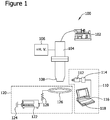
- System 100 includes a syringe pump 102, a nozzle 104, and a high-voltage source 106.
- syringe pump 102 is a Harvard Apparatus PHD2000 series pump.
- syringe pump 102 is any pump that enables system 100 to function as described herein.
- High-voltage source 106 is coupled to nozzle 104 such that high-voltage source 106 enables a voltage to be applied to a spray end 108 of nozzle 104.
- high-voltage source 106 provides a voltage ranging from 13kV to 16 kV to spray end 108.
- high-voltage source may apply any voltage to nozzle 104 that enables system 100 to function as described herein.
- System 100 also includes a monitoring system 110.
- Monitoring system 110 includes a microscopic lens 112, a digital camera 114, a monitor 116, and a computer 118, which enable monitoring system 110 to monitor the spray produced by nozzle 104.
- System 100 also includes a current system 120.
- Current system 120 includes a multimeter 122 electrically coupled to a ground 124 and electrically coupled to ring 126 across a resistor 128. By measuring the voltage across resistor 128, current system 120 can measure the current of the spray produced by nozzle 104. Through multimeter 122, ring 126 is also electrically coupled to ground 124.
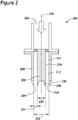
- FIG. 2 is a cross-sectional view of an exemplary nozzle 200 that may be used with system 100, this nozzle not being part of the present invention.
- Nozzle 200 includes a source end 202 and a spray end 204.
- Nozzle 200 includes an inner rod 206 coaxially aligned with an outer tube 208 along a longitudinal axis 210 of nozzle 200.
- An annular flow channel 212 is defined between an inner surface 214 of outer tube 208 and an outer surface 216 of inner rod 206.
- annular flow channel 212 becomes a circular slit 218.
- an inner diameter 220 of circular slit 218 is 2,950 ⁇ m
- an outer diameter 222 of circular slit 218 is 3,250 ⁇ m, such that a width 224 of circular slit 218 is 150 ⁇ m.
- circular slit 218 may have any dimensions that enable nozzle 200 to function as described herein.
- syringe pump 102 applies a pressure to a spray liquid, such that the spray liquid is pushed towards nozzle 200 and received at source end 202 of nozzle 200.
- the spray liquid is then evenly distributed into annular flow channel 212 and emitted from circular slit 218 as a thin liquid sheet.
- the emitted liquid sheet is substantially cylindrical.
- Nozzle 200 further includes one or more notches 230 proximate to circular slit 218.
- a "notch" refers to a protruding element that extends from a spray end of a nozzle, such as notches 230 extending from spray end 204 of nozzle 200.
- such notches may extend or protrude further in the direction of the spray jet than other regions of the spray end separating such notches.
- notches 230 are located on both inner rod 206 and outer tube 208.
- notches 230 may be located only on inner rod 206 or outer tube 208.
- the shape and configuration of notches 230 facilitate local enhancement of an electric field at notches 230.
- the spray liquid reaches the circular slit 218, it exits nozzle 200 as a thin liquid sheet due to the shape of annular flow channel 212.
- the thin liquid sheet is separated into multiple jets. Each jet is located at one of notches 230 due to the locally intensified electric field at each notch 230.
- stable multi-jet operation means that a jet of spray liquid is emitted from each notch 230 on nozzle 200.
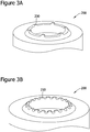
- Figures 3A and 3B are perspective views of exemplary nozzles 200 that may be used with the system of Figure 1 , these nozzles not being part of the present invention.
- Figures 4A and 4B are plan views of the nozzles 200 shown in Figures 3A and 3B .
- the variant shown in Figures 3A and 4A includes six notches 230, and the variant shown in Figures 3B and 4B includes twenty notches 230.
- Notches 230 are circumferentially spaced apart from one another by a circumferential distance, 240.
- circumferential distance 240 is no less than a size of a notch 230.
- Circumferential distance 240 is chosen such that the number of notches 230 is maximized while maintaining regions of intensified electric field.
- Figures 5A-5C are images of nozzles 200 producing multiple jets 250 of a spray liquid, thess nozzles not being part of the present invention.
- the nozzles 200 in Figures 5A, 5B, and 5C include six, twelve, and twenty notches 230, respectively.
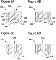
- Figures 6A-6L are cross-sectional views of exemplary nozzles 300 that may be used with the system of Figure 1 , the nozzles of figures 6A to 6G not being part of the present invention and the nozzles of figures 6H to 6L being part of the present invention.
- FIGS 6A-6L several different configurations of nozzle 300 enable nozzle 300 to function as described herein.
- configurations of nozzle 300 are not limited to those specifically described herein.
- Each nozzle 300 in Figures 6A-6L includes a source end 302 and a spray end 304. Further, each nozzle 300 includes an inner rod 306 coaxially aligned with an outer tube 308 along a longitudinal axis 310 of nozzle 300. An annular flow channel 312 is defined between an inner surface 314 of outer tube 308 and an outer surface 316 of inner rod 306. At spray end 304, annular flow channel 312 becomes a circular slit 318. Further, at spray end 304, inner rod 306 includes a center piece 320, and outer tube 308 includes an end portion 322. Each nozzle 300 also includes a plurality of notches 330 which function substantially similar to notches 230 shown in Figure 2 . The variants of Figures 6A-6L are each discussed in detail below.
- both inner rod 306 and outer tube 308 includes notches 330 thereon. Further, center piece 320 is not retracted or extended with respect to end portion 322. During operation of the variant shown in Figure 6A , a spray liquid is emitted from circular slit 318.
- outer tube 308 includes notches 330 thereon. That is, inner rod 306 does not include notches 330. Further, center piece 320 is retracted with respect to end portion 322. During operation of the variant shown in Figure 6B , the spray liquid is emitted from circular slit 318.
- the variant of nozzle 300 shown in Figure 6C is substantially similar to the variant shown in Figure 6A , except that the variant shown in Figure 6C includes a central flow channel 340 defined through inner rod 306.
- the variant of nozzle 300 shown in Figure 6D is substantially similar to the variant shown in Figure 6B , except that the variant shown in Figure 6D includes central flow channel 340 defined through inner rod 306.
- a stabilizing gas is emitted from central flow channel 340. The emitted gas facilitates maintaining the thin liquid sheet shape of the spray liquid when the spray liquid is emitted from circular slit 318.
- the variants of nozzle 300 shown in Figures 6E and 6F are substantially similar to the variants shown in Figures 6C and 6D respectively, except that instead of a stabilizing gas, a stabilizing liquid is emitted from central flow channel 340. Similar to the stabilizing gas, the stabilizing liquid facilitates maintaining the thin liquid sheet shape of the spray liquid when the spray liquid is emitted from circular slit 318.
- the variant of nozzle 300 shown in Figure 6G is substantially similar to the variant shown in Figure 6F , except that center piece 320 is extended with respect to end potion 322.
- nozzle 300 shown in Figures 6H and 6I are substantially similar to the variants shown in Figures 6C and 6D respectively, except that the embodiments of Figures 6H and 6I further include a second outer tube 350.
- Second outer tube 350 is concentrically aligned with outer tube 308 such that a second annular flow channel 352 is defined between an outer surface 354 of outer tube 308 and an inner surface 356 of second outer tube 350.
- Second annular flow channel 352 becomes a second circular slit 360 at spray end 304.
- second outer tube 350 includes notches 330 thereon.
- a sheath liquid is emitted from second circular slit 360 in a thin liquid sheet shape.
- particle encapsulation is facilitated, such that the particles produced by nozzle 300 include particles of spray liquid encapsulated by particles of sheath liquid and/or particles of sheath liquid encapsulated by particles of spray liquid.
- a stabilizing gas emitted from central flow channel 340 facilitates maintaining the thin liquid sheet shape of the spray liquid and the sheath liquid.
- a stabilizing liquid may be emitted from central flow channel 340.
- the embodiment shown in Figure 6J is substantially similar to the embodiment shown in Figure 6I , except that the center piece 320 is extended with respect to end portion 322.
- the embodiment of nozzle 300 shown in Figure 6K is substantially similar to the embodiment shown in Figure 6H , except that the embodiment of Figure 6K further includes a third outer tube 370.
- Third outer tube 370 is concentrically aligned with second outer tube 350 such that a third annular flow channel 372 is defined between an outer surface 374 of second outer tube 350 and an inner surface 376 of third outer tube 370.
- Third annular flow channel 372 becomes a third circular slit 380 at spray end 304.
- third outer tube 370 includes notches 330 thereon.
- an outer liquid is emitted from third circular slit 380 in a thin liquid sheet shape.
- the emission of liquids from first circular slit 318, second circular slit 360, and third circular slit 380 facilitates particle encapsulation and the production of multilayered particles.
- a stabilizing gas emitted from central flow channel 340 facilitates maintaining the thin liquid sheet shape of the emitted liquids.
- a stabilizing liquid may be emitted from central flow channel 340.
- the embodiment shown in Figure 6L is substantially similar to the embodiment shown in Figure 6K , except that the circular slits 318, 360, and 380 are arranged in a stepped configuration, such that outer tube 308 is extended with respect to second outer tube 350, and second outer tube 350 is extended with respect to third outer tube 370. Due to the stepped configuration, less voltage may be applied to the embodiment shown in Figure 6L than the embodiment shown in Figure 6K to achieve stable multi-jet operation.
- the outer liquid emitted from third circular slit 380 may be the same liquid as at least one of the spray liquid emitted from first circular slit 318 and the sheath liquid emitted from second circular slit 360.
- the spray liquid, the sheath liquid, and the outer liquid may all be different liquids.
- certain flow channels are denoted as containing a gas or a liquid, alternatively, any suitable fluid (i.e., gas, liquid) may be provided in any flow channel that enables nozzle 300 to function as described herein.
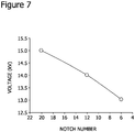
- Figure 7 is a graph that illustrates the applied voltage for establishing stable multi-jet operation for nozzles having various numbers of notches. The graph demonstrates that the applied voltage increases with the number of notches. It was also determined that the applied voltage for establishing stable multi-jet operation is also slightly proportional to the feed flowrate of the spray liquid.
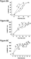
- Figures 8A-8C are graphs illustrating the spray current as a function of the applied voltage for nozzles with six, twelve, and twenty notches, respectively.
- the spray current and the number of jets increased with the increase of applied voltage.
- the stable multi-jet operation in which the number of jets is the same as the number of notches, was achieved at a sufficiently high applied voltage.
- the applied voltage was reduced, the number of jets correspondingly decreased. Further, as shown in the graphs, a hysteresis phenomenon was observed.
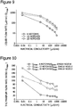
- FIG. 9 is a graph that illustrates the maximum liquid flowrate as a function of the electrical conductivity of the spray liquid.
- the graph demonstrates that the value of Qmax significantly decreases as the electrical conductivity of the spraying liquid increases, due to the fact that spray liquids with higher electrical conductivity generally use a stronger electric field to establish stable multi-jet operation.
- the graph also demonstrates that Qmax increases as the number of notches increases. This is because a greater number of notches allow more jets to be established, thus increasing the spray liquid flowrate and the overall mass throughput.
- Figure 10 is a graph illustrating a ratio of the maximum liquid flowrate of the liquid sheet nozzles described herein to the maximum liquid flowrate of a known single-capillary nozzle as a function of the electrical conductivity of the spray liquid.
- the diameter of the single-capillary nozzle and the width of the circular slit in the liquid sheet nozzle were both 150 ⁇ m.
- the maximum liquid flowrate, Qmax, of the liquid sheet nozzle with 20 notches was one hundred and sixty-six times greater than the maximum liquid flowrate for the single-capillary nozzle.
- the maximum liquid flowrate of the liquid sheet nozzle with twenty notches was seventy times greater than the maximum liquid flowrate for the single-capillary nozzle.
- the value of Qmax for a liquid sheet nozzle with twenty notches is much higher than the sum of the total liquid flowrates for twenty single-capillary nozzles.
- This same phenomenon was also observed using liquid sheet nozzles with six and twelve notches. This indicates that, as compared to existing one-dimensional and two-dimensional arrays of single-capillary nozzles, liquid sheet nozzles have potential to drastically increase the mass throughput for spray liquids having a wide range of electrical conductivity.
- FIG 11 is a plan view of an alternative nozzle 500 that may be used with system 100, this nozzle not being part of the present invention.
- Figure 12 is a perspective view of nozzle 500 shown in Figure 11 .
- nozzle 500 includes a first plate 502, a second plate 504, a source end 506, and a spray end 508.
- a planar flow channel 510 is defined between first plate 502 and second plate 504. Planar flow channel 510 becomes a linear slit 512 at spray end 508.
- a spray liquid is emitted from nozzle 500 from linear slit 512. While the thin liquid sheet emitted from nozzle 200 is substantially cylindrical, the thin liquid sheet emitted from nozzle 500 is substantially planar.
- a plurality of notches 514 are located on both first plate 502 and second plate 504, and staggered with respect to one another.
- notches 514 may only be located on one of first plate 502 and second plate 504. With a voltage applied to notches 514, notches 514 facilitate separating the thin liquid sheet into a plurality of jets, substantially similar to notches 230 of nozzle 200.
- the nozzles illustrated in Figures 1-6L , 11, and 12 constitute exemplary means for emitting a liquid sheet. Further, the notches illustrated in Figures 2-6L , 11, and 12 constitute exemplary means for separating a liquid sheet emitted by a nozzle into multiple jets. Moreover, nozzles illustrated in Figures 6C-6L constitute exemplary means for maintaining a shape of a liquid sheet emitted from a nozzle.
- Embodiments described herein enable electrohydrodynamic atomization, or electrospray (ES), using nozzles that produce a thin liquid sheet.
- the methods and systems described herein increase the mass throughput of ES systems while decreasing the design and manufacturing costs as compared to known ES systems utilizing multiple single-capillary nozzles.
- the nozzles described herein include annular and/or planar slits designed emit a thin liquid sheet of spray liquid.
- a plurality of notches are included at the annular and/or planar slits. That is, each notch anchors a corresponding jet by preventing the corresponding jet from migrating around the nozzle, substantially fixing the position of the corresponding jet.
- these notches enable local enhancement of an electric field.
- stable multi-jet operation of the nozzles described herein can be established for a wide range of spray liquids having various electrical conductivities.
- the applied voltage for establishing stable multi-jet operation increased as both the number of jets and the liquid flowrate increased.
- the maximum operational flowrate through the nozzles described herein was a function of the electrical conductivity of the spray liquid.
- the maximum flowrate for liquid sheet nozzles with various numbers of notches was consistently greater than the total flowrate sum of an array of an equivalent number of single-capillary nozzles. Accordingly, the liquid sheet nozzles described herein enable superior ES techniques.
- the liquid sheet shape of the spray liquid as opposed to the cone jet emitted from known single-capillary nozzles, enables the nozzle design to have various geometries, including, but not limited to annular and/or planar slits.
Landscapes
- Chemical & Material Sciences (AREA)
- Organic Chemistry (AREA)
- Chemical Kinetics & Catalysis (AREA)
- Electrostatic Spraying Apparatus (AREA)
- Nozzles (AREA)
- Glanulating (AREA)
Description
- Electrohydrodynamic atomization, often called electrospray (ES), has recently attracted great attention for potential and practical particle applications in fine powder production, food processing, medicine, pharmaceutics, biology, and chemistry. The technique enables the production of un-agglomerated, monodisperse particles of various materials with sizes ranging from micro-meter to nano-meter. In known ES systems, a liquid meniscus at the exit of a capillary nozzle is subjected to an electrical stress, resulting from a divergent electrical field established between a spray head and a reference electrode. Due to the geometry of capillary nozzles, however, known ES systems have low mass throughput, which makes the feasibility of large scale implementation difficult.
-
EP 0250164A2 discloses an apparatus which can be used to create granular materials or powders via the electrostatic spraying of liquids which cure in flight. - Each of documents
WO 2010/149197 A1 andUS 2008/308095 A1 discloses a nozzle that differs from the nozzle according toclaim 1 in that the nozzle according toclaim 1 further comprises an outermost tube concentrically aligned with said inner rod and said outer tube such that an outer flow channel is defined between said outer tube and said outermost tube and in that it further comprises at least one electrically chargeable notch located on said outermost tube. - Several recent electrohydrodynamic atomization techniques reportedly increase the mass throughput. For example, in a single-capillary ES nozzle, a multi-jet mode can be generated when the applied voltage exceeds a voltage range for a cone-jet mode. However, multiple liquid jets initiated from a single-capillary head are unstable. Arranging a number of individual capillaries in a one-dimensional linear array also increases the total spray liquid flowrate. However, although the one-dimensional arrangement of individual capillaries is easy to construct for laboratory investigation, it is not practical for industrial scale applications. Further each individual capillary uses a separate feeding and/or distribution channel.
- In a first aspect, a nozzle for electrohydrodynamic atomization according to
claim 1 is provided. - In another aspect, a system for electrohydrodynamic atomization according to claim 7 is provided.
- In yet another aspect, a method for electrohydrodynamic atomization according to
claim 9 is provided. - The embodiments described herein may be better understood by referring to the following description in conjunction with the accompanying drawings.
-
Figure 1 is a schematic diagram of an exemplary electrospray system. -
Figure 2 is a cross-sectional view of an exemplary nozzle that may be used with the system ofFigure 1 , this nozzle not being part of the present invention. -
Figures 3A and 3B are perspective views of exemplary nozzles that may be used with the system ofFigure 1 , these nozzles not being part of the present invention. -
Figures 4A and 4B are plan views of the exemplary nozzles ofFigures 3B and 3B . -
Figures 5A-5C are images of exemplary nozzles that may be used with the system ofFigure 1 , these nozzles not being part of the present invention. -
Figures 6A-6L are cross-sectional views of exemplary nozzles that may be used with the system ofFigure 1 , the nozzles offigures 6A to 6G not being part of the present invention and the nozzles offigures 6H to 6L being part of the present invention. -
Figure 7 is a graph that illustrates the applied voltage for establishing stable multi-jet operation for nozzles of various numbers of notches. -
Figures 8A-8C are graphs illustrating spray current as a function of applied voltage for nozzles with six, twelve, and twenty notches. -
Figure 9 is a graph that illustrates maximum liquid flowrate as a function of electrical conductivity of a spray liquid. -
Figure 10 is a graph illustrating a ratio of maximum liquid flowrate of a liquid sheet nozzle to the maximum liquid flowrate of a single-capillary nozzle. -
Figure 11 is a plan view of an exemplary nozzle that may be used with the system ofFigure 1 , this nozzle not being part of the present invention. -
Figure 12 is a perspective view of the exemplary nozzle shown inFigure 11 . - Embodiments provide electrohydrodynamic atomization using a liquid sheet to produce un-agglomerated, monodisperse droplets. In contrast to the capillaries/tubes used in known electrospray (ES) systems, nozzles with exit slit openings shape a spray liquid into a thin liquid sheet as the spray liquid exits from the slit opening. Stable multi-jet operation is achieved by including notches along the edge of the slit. The notches separate the liquid sheet into multiple jets to provide anchoring and stable multi-jet operation. That is, each notch anchors a corresponding jet by preventing the corresponding jet from migrating around the nozzle, substantially fixing the position of the corresponding jet. In some embodiments, the liquid sheet electrospray techniques and nozzles described herein provide high mass throughput and versatile multiplexing spray systems while reducing the engineering effort and high manufacturing cost.
- A schematic diagram of an
exemplary electrospray system 100 is shown inFigure 1 .System 100 includes asyringe pump 102, anozzle 104, and a high-voltage source 106. In an exemplary embodiment,syringe pump 102 is a Harvard Apparatus PHD2000 series pump. Alternatively,syringe pump 102 is any pump that enablessystem 100 to function as described herein. - High-
voltage source 106 is coupled tonozzle 104 such that high-voltage source 106 enables a voltage to be applied to aspray end 108 ofnozzle 104. In an exemplary embodiment, high-voltage source 106 provides a voltage ranging from 13kV to 16 kV to sprayend 108. Alternatively, high-voltage source may apply any voltage tonozzle 104 that enablessystem 100 to function as described herein. -
System 100 also includes amonitoring system 110.Monitoring system 110 includes amicroscopic lens 112, adigital camera 114, amonitor 116, and acomputer 118, which enablemonitoring system 110 to monitor the spray produced bynozzle 104. -
System 100 also includes acurrent system 120.Current system 120 includes amultimeter 122 electrically coupled to aground 124 and electrically coupled toring 126 across aresistor 128. By measuring the voltage acrossresistor 128,current system 120 can measure the current of the spray produced bynozzle 104. Throughmultimeter 122,ring 126 is also electrically coupled toground 124. -
Figure 2 is a cross-sectional view of anexemplary nozzle 200 that may be used withsystem 100, this nozzle not being part of the present invention. Nozzle 200 includes asource end 202 and aspray end 204. Nozzle 200 includes aninner rod 206 coaxially aligned with anouter tube 208 along alongitudinal axis 210 ofnozzle 200. Anannular flow channel 212 is defined between aninner surface 214 ofouter tube 208 and anouter surface 216 ofinner rod 206. Atspray end 204,annular flow channel 212 becomes acircular slit 218. In a variant, aninner diameter 220 ofcircular slit 218 is 2,950 µm, and anouter diameter 222 ofcircular slit 218 is 3,250 µm, such that awidth 224 ofcircular slit 218 is 150 µm. Alternativelycircular slit 218 may have any dimensions that enablenozzle 200 to function as described herein. - In operation,
syringe pump 102 applies a pressure to a spray liquid, such that the spray liquid is pushed towardsnozzle 200 and received atsource end 202 ofnozzle 200. The spray liquid is then evenly distributed intoannular flow channel 212 and emitted fromcircular slit 218 as a thin liquid sheet. In the variant shown inFigure 2 , the emitted liquid sheet is substantially cylindrical. -
Nozzle 200 further includes one ormore notches 230 proximate tocircular slit 218. As used herein, a "notch" refers to a protruding element that extends from a spray end of a nozzle, such asnotches 230 extending fromspray end 204 ofnozzle 200. For example, such notches may extend or protrude further in the direction of the spray jet than other regions of the spray end separating such notches. In a variant,notches 230 are located on bothinner rod 206 andouter tube 208. Alternatively,notches 230 may be located only oninner rod 206 orouter tube 208. When high-voltage source 106 applies a voltage to spray end 204 ofnozzle 200, the shape and configuration ofnotches 230 facilitate local enhancement of an electric field atnotches 230. When the spray liquid reaches thecircular slit 218, it exitsnozzle 200 as a thin liquid sheet due to the shape ofannular flow channel 212. With a sufficiently high voltage applied to spray end 204 ofnozzle 200, the thin liquid sheet is separated into multiple jets. Each jet is located at one ofnotches 230 due to the locally intensified electric field at eachnotch 230. Further, with a high enough voltage applied to sprayend 204, stable multi-jet operation may be achieved. In some embodiments, "stable multi-jet operation" means that a jet of spray liquid is emitted from eachnotch 230 onnozzle 200. -
Figures 3A and 3B are perspective views ofexemplary nozzles 200 that may be used with the system ofFigure 1 , these nozzles not being part of the present invention.Figures 4A and 4B are plan views of thenozzles 200 shown inFigures 3A and 3B . The variant shown inFigures 3A and4A includes sixnotches 230, and the variant shown inFigures 3B and4B includes twentynotches 230.Notches 230 are circumferentially spaced apart from one another by a circumferential distance, 240. In some variants,circumferential distance 240 is no less than a size of anotch 230.Circumferential distance 240 is chosen such that the number ofnotches 230 is maximized while maintaining regions of intensified electric field. That is, ifcircumferential distance 240 betweennotches 230 is too small, the electric field generated at onenotch 230 will interfere with the electric field generated at anadjacent notch 230. However, as thecircumferential distance 240 betweennotches 230 increases,fewer notches 230 can be located onnozzle 200. Withfewer notches 230, fewer jets are created, and the overall mass throughput ofnozzle 200 is decreased. -
Figures 5A-5C are images ofnozzles 200 producingmultiple jets 250 of a spray liquid, thess nozzles not being part of the present invention. Thenozzles 200 inFigures 5A, 5B, and 5C include six, twelve, and twentynotches 230, respectively. -
Figures 6A-6L are cross-sectional views ofexemplary nozzles 300 that may be used with the system ofFigure 1 , the nozzles offigures 6A to 6G not being part of the present invention and the nozzles offigures 6H to 6L being part of the present invention. As demonstrated by the variants shown inFigures 6A-6L , several different configurations ofnozzle 300 enablenozzle 300 to function as described herein. Moreover, configurations ofnozzle 300 are not limited to those specifically described herein. - Each
nozzle 300 inFigures 6A-6L includes asource end 302 and aspray end 304. Further, eachnozzle 300 includes aninner rod 306 coaxially aligned with anouter tube 308 along alongitudinal axis 310 ofnozzle 300. Anannular flow channel 312 is defined between aninner surface 314 ofouter tube 308 and anouter surface 316 ofinner rod 306. Atspray end 304,annular flow channel 312 becomes acircular slit 318. Further, atspray end 304,inner rod 306 includes acenter piece 320, andouter tube 308 includes anend portion 322. Eachnozzle 300 also includes a plurality ofnotches 330 which function substantially similar tonotches 230 shown inFigure 2 . The variants ofFigures 6A-6L are each discussed in detail below. - In the variant of
nozzle 300 shown inFigure 6A , bothinner rod 306 andouter tube 308 includesnotches 330 thereon. Further,center piece 320 is not retracted or extended with respect to endportion 322. During operation of the variant shown inFigure 6A , a spray liquid is emitted fromcircular slit 318. - In the variant of
nozzle 300 shown inFigure 6B , onlyouter tube 308 includesnotches 330 thereon. That is,inner rod 306 does not includenotches 330. Further,center piece 320 is retracted with respect to endportion 322. During operation of the variant shown inFigure 6B , the spray liquid is emitted fromcircular slit 318. - The variant of
nozzle 300 shown inFigure 6C is substantially similar to the variant shown inFigure 6A , except that the variant shown inFigure 6C includes acentral flow channel 340 defined throughinner rod 306. Likewise, the variant ofnozzle 300 shown inFigure 6D is substantially similar to the variant shown inFigure 6B , except that the variant shown inFigure 6D includescentral flow channel 340 defined throughinner rod 306. In the variants ofFigures 6C and 6D , a stabilizing gas is emitted fromcentral flow channel 340. The emitted gas facilitates maintaining the thin liquid sheet shape of the spray liquid when the spray liquid is emitted fromcircular slit 318. - The variants of
nozzle 300 shown inFigures 6E and 6F are substantially similar to the variants shown inFigures 6C and 6D respectively, except that instead of a stabilizing gas, a stabilizing liquid is emitted fromcentral flow channel 340. Similar to the stabilizing gas, the stabilizing liquid facilitates maintaining the thin liquid sheet shape of the spray liquid when the spray liquid is emitted fromcircular slit 318. The variant ofnozzle 300 shown inFigure 6G is substantially similar to the variant shown inFigure 6F , except thatcenter piece 320 is extended with respect to endpotion 322. - The embodiments of
nozzle 300 shown inFigures 6H and6I are substantially similar to the variants shown inFigures 6C and 6D respectively, except that the embodiments ofFigures 6H and6I further include a secondouter tube 350. Secondouter tube 350 is concentrically aligned withouter tube 308 such that a secondannular flow channel 352 is defined between anouter surface 354 ofouter tube 308 and aninner surface 356 of secondouter tube 350. Secondannular flow channel 352 becomes a secondcircular slit 360 atspray end 304. - In the embodiments shown in
Figures 6H and6I , secondouter tube 350 includesnotches 330 thereon. In addition to the spray liquid emitted from firstcircular slit 318, a sheath liquid is emitted from secondcircular slit 360 in a thin liquid sheet shape. With the spray liquid and the sheath liquid both emitted fromnozzle 300, particle encapsulation is facilitated, such that the particles produced bynozzle 300 include particles of spray liquid encapsulated by particles of sheath liquid and/or particles of sheath liquid encapsulated by particles of spray liquid. Similar to the variants shown inFigure 6C and 6D , a stabilizing gas emitted fromcentral flow channel 340 facilitates maintaining the thin liquid sheet shape of the spray liquid and the sheath liquid. Alternatively, similar toFigures 6E-6G , a stabilizing liquid may be emitted fromcentral flow channel 340. The embodiment shown inFigure 6J is substantially similar to the embodiment shown inFigure 6I , except that thecenter piece 320 is extended with respect to endportion 322. - The embodiment of
nozzle 300 shown inFigure 6K is substantially similar to the embodiment shown inFigure 6H , except that the embodiment ofFigure 6K further includes a thirdouter tube 370. Thirdouter tube 370 is concentrically aligned with secondouter tube 350 such that a thirdannular flow channel 372 is defined between an outer surface 374 of secondouter tube 350 and aninner surface 376 of thirdouter tube 370. Thirdannular flow channel 372 becomes a thirdcircular slit 380 atspray end 304. - In the embodiment shown in
Figure 6K , thirdouter tube 370 includesnotches 330 thereon. In addition to the spray liquid emitted from firstcircular slit 318 and the sheath liquid emitted from secondcircular slit 360, an outer liquid is emitted from thirdcircular slit 380 in a thin liquid sheet shape. The emission of liquids from firstcircular slit 318, secondcircular slit 360, and thirdcircular slit 380 facilitates particle encapsulation and the production of multilayered particles. Similar to the variants shown inFigure 6C and 6D , a stabilizing gas emitted fromcentral flow channel 340 facilitates maintaining the thin liquid sheet shape of the emitted liquids. Alternatively, similar toFigures 6E-6G , a stabilizing liquid may be emitted fromcentral flow channel 340. - The embodiment shown in
Figure 6L is substantially similar to the embodiment shown inFigure 6K , except that thecircular slits outer tube 308 is extended with respect to secondouter tube 350, and secondouter tube 350 is extended with respect to thirdouter tube 370. Due to the stepped configuration, less voltage may be applied to the embodiment shown inFigure 6L than the embodiment shown inFigure 6K to achieve stable multi-jet operation. In the embodiments shown inFigures 6L and 6K , the outer liquid emitted from thirdcircular slit 380 may be the same liquid as at least one of the spray liquid emitted from firstcircular slit 318 and the sheath liquid emitted from secondcircular slit 360. Alternatively, the spray liquid, the sheath liquid, and the outer liquid may all be different liquids. Furthermore, while in the variants shown inFigures 6A-6L , certain flow channels are denoted as containing a gas or a liquid, alternatively, any suitable fluid (i.e., gas, liquid) may be provided in any flow channel that enablesnozzle 300 to function as described herein. - Multiple experiments were executed utilizing the nozzles described herein. In the following examples, Isopropanol was selected as the spray liquid, and nitric acid was used as an ion additive to vary the electrical conductivity of the spray liquid from 0.0079 µS/cm (pure isopropanol) to 1,044 µS/cm. The electrical conductivity of the spray liquid was measured by a conductivity meter (Orion 162A, Thermo Electron Corporation), and the electrical resistance of pure isopropanol was measured by a lab-made liquid cell. Alternatively, those of ordinary skill in the art will understand that any spray liquid may be utilized which allows
system 100 to function as described herein. -
Figure 7 is a graph that illustrates the applied voltage for establishing stable multi-jet operation for nozzles having various numbers of notches. The graph demonstrates that the applied voltage increases with the number of notches. It was also determined that the applied voltage for establishing stable multi-jet operation is also slightly proportional to the feed flowrate of the spray liquid. - In one example, to study the evolution in the formation of multiple jets, the spray current was measured, and the number of jets was counted as the applied voltage was continuously increased and then decreased.
Figures 8A-8C are graphs illustrating the spray current as a function of the applied voltage for nozzles with six, twelve, and twenty notches, respectively. The spray current and the number of jets increased with the increase of applied voltage. The stable multi-jet operation, in which the number of jets is the same as the number of notches, was achieved at a sufficiently high applied voltage. When the applied voltage was reduced, the number of jets correspondingly decreased. Further, as shown in the graphs, a hysteresis phenomenon was observed. - In another example, to determine the mass throughput of the nozzles, spray liquids with various electrical conductivities were used to find the maximum liquid flowrate (Qmax) for nozzle operation.
Figure 9 is a graph that illustrates the maximum liquid flowrate as a function of the electrical conductivity of the spray liquid. The graph demonstrates that the value of Qmax significantly decreases as the electrical conductivity of the spraying liquid increases, due to the fact that spray liquids with higher electrical conductivity generally use a stronger electric field to establish stable multi-jet operation. The graph also demonstrates that Qmax increases as the number of notches increases. This is because a greater number of notches allow more jets to be established, thus increasing the spray liquid flowrate and the overall mass throughput. -
Figure 10 is a graph illustrating a ratio of the maximum liquid flowrate of the liquid sheet nozzles described herein to the maximum liquid flowrate of a known single-capillary nozzle as a function of the electrical conductivity of the spray liquid. In this example, the diameter of the single-capillary nozzle and the width of the circular slit in the liquid sheet nozzle were both 150 µm. As illustrated in the graph ofFigure 10 , when using a spray liquid with an electrical conductivity of 0.0079 µS/cm, the maximum liquid flowrate, Qmax, of the liquid sheet nozzle with 20 notches was one hundred and sixty-six times greater than the maximum liquid flowrate for the single-capillary nozzle. Further, when using a spray liquid with an electrical conductivity of 1,044 µS/cm µS/cm, the maximum liquid flowrate of the liquid sheet nozzle with twenty notches was seventy times greater than the maximum liquid flowrate for the single-capillary nozzle. - Notably, the value of Qmax for a liquid sheet nozzle with twenty notches is much higher than the sum of the total liquid flowrates for twenty single-capillary nozzles. This same phenomenon was also observed using liquid sheet nozzles with six and twelve notches. This indicates that, as compared to existing one-dimensional and two-dimensional arrays of single-capillary nozzles, liquid sheet nozzles have potential to drastically increase the mass throughput for spray liquids having a wide range of electrical conductivity.
-
Figure 11 is a plan view of analternative nozzle 500 that may be used withsystem 100, this nozzle not being part of the present invention.Figure 12 is a perspective view ofnozzle 500 shown inFigure 11 . In variant,nozzle 500 includes afirst plate 502, asecond plate 504, asource end 506, and aspray end 508. Aplanar flow channel 510 is defined betweenfirst plate 502 andsecond plate 504.Planar flow channel 510 becomes alinear slit 512 atspray end 508. In operation, a spray liquid is emitted fromnozzle 500 fromlinear slit 512. While the thin liquid sheet emitted fromnozzle 200 is substantially cylindrical, the thin liquid sheet emitted fromnozzle 500 is substantially planar. - In a variant, a plurality of
notches 514 are located on bothfirst plate 502 andsecond plate 504, and staggered with respect to one another. Alternatively,notches 514 may only be located on one offirst plate 502 andsecond plate 504. With a voltage applied tonotches 514,notches 514 facilitate separating the thin liquid sheet into a plurality of jets, substantially similar tonotches 230 ofnozzle 200. - The nozzles illustrated in
Figures 1-6L ,11, and 12 constitute exemplary means for emitting a liquid sheet. Further, the notches illustrated inFigures 2-6L ,11, and 12 constitute exemplary means for separating a liquid sheet emitted by a nozzle into multiple jets. Moreover, nozzles illustrated inFigures 6C-6L constitute exemplary means for maintaining a shape of a liquid sheet emitted from a nozzle. - In addition to the cylindrical and planar nozzles specifically described herein, those of ordinary skill in the art will understand that any nozzle shape and/or configuration may be utilized which allows
system 100 to function as described herein. - Embodiments described herein enable electrohydrodynamic atomization, or electrospray (ES), using nozzles that produce a thin liquid sheet. The methods and systems described herein increase the mass throughput of ES systems while decreasing the design and manufacturing costs as compared to known ES systems utilizing multiple single-capillary nozzles. The nozzles described herein include annular and/or planar slits designed emit a thin liquid sheet of spray liquid. To separate the thin liquid sheet into multiple jets and to anchor the jets for stable operation, a plurality of notches are included at the annular and/or planar slits. That is, each notch anchors a corresponding jet by preventing the corresponding jet from migrating around the nozzle, substantially fixing the position of the corresponding jet. When a voltage is applied to the nozzles described herein, these notches enable local enhancement of an electric field. Further, stable multi-jet operation of the nozzles described herein can be established for a wide range of spray liquids having various electrical conductivities.
- Moreover, as compared to known ES systems utilizing arrays of single-capillary nozzles, multiple liquid flow feeding and/or distribution channels are no longer necessary for the nozzles described herein. As such, the design concept and fabrication of the nozzles described herein is simpler than known nozzles, enabling flexibility in the design and/or geometry of the nozzles.
- Through experimentation utilizing the nozzles described herein, it was demonstrated that the applied voltage for establishing stable multi-jet operation increased as both the number of jets and the liquid flowrate increased. Further, the maximum operational flowrate through the nozzles described herein was a function of the electrical conductivity of the spray liquid. Moreover, the maximum flowrate for liquid sheet nozzles with various numbers of notches was consistently greater than the total flowrate sum of an array of an equivalent number of single-capillary nozzles. Accordingly, the liquid sheet nozzles described herein enable superior ES techniques. Further, the liquid sheet shape of the spray liquid, as opposed to the cone jet emitted from known single-capillary nozzles, enables the nozzle design to have various geometries, including, but not limited to annular and/or planar slits.
- The order of execution or performance of the operations in the embodiments of the disclosure illustrated and described herein is not essential, unless otherwise specified. That is, the operations may be performed in any order, unless otherwise specified. For example, it is contemplated that executing or performing a particular operation before, contemporaneously with, or after another operation is within the scope of aspects of the disclosure.
- When introducing elements of aspects of the disclosure or embodiments thereof, the articles "a," "an," "the," and "said" are intended to mean that there are one or more of the elements. The terms "comprising," including," and "having" are intended to be inclusive and mean that there may be additional elements other than the listed elements.
- This written description uses examples to disclose the disclosure, including the best mode, and also to enable any person skilled in the art to practice the disclosure, including making and using any devices or systems and performing any incorporated methods. The patentable scope of the disclosure is defined by the claims, and may include other examples that occur to those skilled in the art. Such other examples are intended to be within the scope of the claims if they have structural elements that do not differ from the literal language of the claims, or if they include equivalent structural elements with insubstantial differences from the literal language of the claims.
Claims (11)
- A nozzle (300) for electrohydrodynamic atomization, said nozzle comprising:an inner rod (306); an outer tube (308) concentrically aligned with said inner rod (306); an annular channel (312) defined between said inner rod (306) and said outer tube (308); said annular channel (312) forming a circular slit (318) at a spray end (304) of said nozzle;at least one electrically chargeable notch (330) located on at least one of said inner rod (306) and said outer tube (308) proximate said circular slit (318); an outermost tube (350, 370) concentrically aligned with said inner rod (306) and said outer tube (308) such that an outer flow channel (352, 372) is defined between said outer tube (308) and said outermost tube (350, 370); andat least one electrically chargeable notch (330) located on said outermost tube (350, 370).
- A nozzle (300) in accordance with Claim 1, wherein said inner rod (306) comprises a central flow channel (340) defined therethrough, and wherein said central flow channel (340) is configured to facilitate flow of at least one of a stabilizing gas and a stabilizing liquid therethrough.
- A nozzle (300) in accordance with Claim 1, wherein only one of said inner rod (306) and said outer tube (308) includes at least one electrically chargeable notch (330).
- A nozzle (300) in accordance with Claim 1, wherein said inner rod (306) comprises a center piece (320) at the spray end of said nozzle and said outer tube (308) comprises an end portion (322) at the spray end of said nozzle, said center piece (320) recessed with respect to said end portion (322).
- A nozzle (300) in accordance with Claim 1, wherein said inner rod (306) comprises a center piece (320) at the spray end of said nozzle and said outer tube (308) comprises an end portion (322) at the spray end of said nozzle, said center piece (320) extended with respect to said end portion (322).
- A nozzle (300) in accordance with Claim 1, wherein said at least one electrically chargeable notch (330) located on at least one of said inner rod (306) and outer tube (308) comprises a plurality of notches, said plurality of notches spaced a distance apart from one another such that when said plurality of notches (330) are electrically charged, an electric field produced by one notch of said plurality of notches does not interfere with an electric field produced by an adjacent notch of said plurality of notches.
- A system (100) for electrohydrodynamic atomization, said system comprising:a nozzle (300) as set forth in Claim 1;a voltage source (106) electrically coupled to said nozzle (300) and configured to supply a voltage to said at least one electrically chargeable notch; anda syringe pump (102) in flow communication with a source end of said nozzle (300), said syringe pump (102) configured to propel a spray liquid through said nozzle (300).
- A system in accordance with Claim 7, wherein said at least one electrically chargeable notch (330) comprises a first notch located on at least one of said inner rod (306) and said outer tube (308) and a second notch, said first and second notches spaced a distance apart from one another such that when a voltage is supplied to said first and second notches, an electric field produced by said first notch does not interfere with an electric field produced by said second notch.
- A method for electrohydrodynamic atomization, said method comprising:providing a nozzle (300) comprising an inner rod (306), an outer tube (308) concentrically aligned with the inner rod (306), an annular channel (312) defined between the inner rod (306) and the outer tube (308), the annular channel (312) forming a circular slit (318) at a spray end of the nozzle (300), and a plurality of notches (330) located on at least one of the inner rod (306) and the outer tube (308) proximate the circular slit (318); supplying a voltage to the plurality of notches (330); pumping a spray liquid through the annular channel (312) of the nozzle (300); providing an outermost tube (350, 370) concentrically aligned with the inner rod (306) and the outer tube (308), such that an outer flow channel (352, 372) is formed between the outer tube (308) and the outermost tube (350, 370); andpumping a sheath liquid through the outer flow channel (352, 372).
- A method in accordance with Claim 9, wherein the inner rod (306) includes a central flow channel (340) defined therethrough, said method further comprising pumping at least one of a stabilizing gas and a stabilizing liquid through the central flow channel (340).
- A method in accordance with Claim 9, wherein supplying a voltage comprises supplying a voltage such that a jet of spray liquid is formed at each of the plurality of notches.
Applications Claiming Priority (2)
| Application Number | Priority Date | Filing Date | Title |
|---|---|---|---|
| US201161434249P | 2011-01-19 | 2011-01-19 | |
| PCT/US2012/021723 WO2012099961A2 (en) | 2011-01-19 | 2012-01-18 | Electrohydrodynamic atomization nozzle emitting a liquid sheet |
Publications (3)
| Publication Number | Publication Date |
|---|---|
| EP2665559A2 EP2665559A2 (en) | 2013-11-27 |
| EP2665559A4 EP2665559A4 (en) | 2017-06-28 |
| EP2665559B1 true EP2665559B1 (en) | 2018-07-18 |
Family
ID=46516346
Family Applications (1)
| Application Number | Title | Priority Date | Filing Date |
|---|---|---|---|
| EP12736538.5A Not-in-force EP2665559B1 (en) | 2011-01-19 | 2012-01-18 | Electrohydrodynamic atomization nozzle emitting a liquid sheet |
Country Status (5)
| Country | Link |
|---|---|
| US (3) | US10562048B2 (en) |
| EP (1) | EP2665559B1 (en) |
| JP (1) | JP5961630B2 (en) |
| CA (1) | CA2824930A1 (en) |
| WO (1) | WO2012099961A2 (en) |
Families Citing this family (24)
| Publication number | Priority date | Publication date | Assignee | Title |
|---|---|---|---|---|
| US6764720B2 (en) | 2000-05-16 | 2004-07-20 | Regents Of The University Of Minnesota | High mass throughput particle generation using multiple nozzle spraying |
| US10562048B2 (en) * | 2011-01-19 | 2020-02-18 | Nanocopoeia, Llc | Electrohydrodynamic atomization nozzle emitting a liquid sheet |
| KR101388174B1 (en) * | 2012-08-09 | 2014-04-22 | 주식회사 엠엠테크 | Blade module and apparatus for treating of substrate |
| CN106687218B (en) | 2014-09-04 | 2019-11-12 | 胜利创新公司 | Electrostatic Fluid Delivery System |
| US20160235677A1 (en) | 2014-11-25 | 2016-08-18 | Nanocopoeia, Llc. | Method of converting a crystalline compound to an amorphous compound, method of increasing the solubility of a crystalline compound in a biorelevant fluid, and nanoparticles that achieve supersaturation |
| US20160175881A1 (en) | 2014-12-22 | 2016-06-23 | Nanocopoeia, Llc | Electrospray methods, electrospray systems, and methods of forming crystalline particles |
| DK178701B1 (en) * | 2015-04-01 | 2016-11-21 | Spx Flow Tech Danmark As | A method and a system for monitoring spray nozzles in a spray drying or spray cooling chamber |
| JP6507028B2 (en) * | 2015-05-21 | 2019-04-24 | 東レエンジニアリング株式会社 | Electro spray device |
| EP3799962A1 (en) | 2015-12-21 | 2021-04-07 | Victory Innovations Company | Electrostatic fluid delivery backpack system |
| JP6880367B2 (en) * | 2016-11-28 | 2021-06-02 | アネスト岩田株式会社 | Electrostatic spraying device and electrostatic spraying method |
| WO2018148348A1 (en) | 2017-02-09 | 2018-08-16 | Virginia Commonwealth University | Electrohydrodynamic (ehd) jet printing with multi-channel jetting apparatuses and systems |
| US20200121867A1 (en) * | 2017-04-20 | 2020-04-23 | Victory Innovations Company | Electrostatic stem cell fluid delivery system |
| KR102084839B1 (en) * | 2018-01-10 | 2020-03-04 | 안상권 | injection syringe |
| WO2019229722A1 (en) * | 2018-06-01 | 2019-12-05 | Avectas Limited | Cell engineering platform |
| EP3971564B1 (en) * | 2019-07-31 | 2024-04-24 | National Institute Of Advanced Industrial Science and Technology | Spray ionization device, analysis device, and surface coating device |
| CA3168667A1 (en) | 2020-01-24 | 2021-07-29 | Nanocopoeia, Llc | Amorphous solid dispersions of dasatinib and uses thereof |
| EP4096791A1 (en) | 2020-01-31 | 2022-12-07 | Nanocopoeia LLC | Amorphous nilotinib microparticles and uses thereof |
| IL297776A (en) | 2020-04-30 | 2022-12-01 | Nanocopoeia Llc | Orally disintegrating tablet comprising amorphous solid dispersion of nilotinib |
| WO2022040446A1 (en) | 2020-08-19 | 2022-02-24 | Nanocopoeia, Llc | Amorphous pazopanib particles and pharmaceutical compositions thereof |
| CA3202761A1 (en) | 2020-11-25 | 2022-06-02 | Nanocopoeia, Llc | Amorphous cabozantinib particles and uses thereof |
| JP7585745B2 (en) * | 2020-11-30 | 2024-11-19 | 新東工業株式会社 | Nozzle, developing device, and processing method for processed object |
| US11980619B2 (en) | 2021-07-28 | 2024-05-14 | Nanocopoeia, Llc | Pharmaceutical compositions and crushable tablets including amorphous solid dispersions of dasatinib and uses |
| KR102578631B1 (en) * | 2022-10-06 | 2023-09-15 | 주식회사 솔탑 | Circular electrospray |
| KR102549347B1 (en) * | 2022-10-06 | 2023-06-30 | 주식회사 솔탑 | Capillary Electrospray |
Family Cites Families (31)
| Publication number | Priority date | Publication date | Assignee | Title |
|---|---|---|---|---|
| US2313994A (en) * | 1941-07-24 | 1943-03-16 | Akron Brass Mfg Company Inc | Spray nozzle |
| US2396449A (en) * | 1945-03-08 | 1946-03-12 | Spraying Systems Co | Spray nozzle |
| US3012733A (en) * | 1960-05-19 | 1961-12-12 | Akron Brass Mfg Company Inc | Nozzle |
| AU517923B2 (en) * | 1977-02-07 | 1981-09-03 | Ransburg Japan Ltd. | Rotary paint atomizing device |
| JPS5829150B2 (en) * | 1977-12-03 | 1983-06-21 | ナカヤ産業株式会社 | spray device |
| JPS5697566A (en) * | 1979-12-21 | 1981-08-06 | Ici Ltd | Vessel used for electrostatic atomizing and its holder |
| GB8504254D0 (en) * | 1985-02-19 | 1985-03-20 | Ici Plc | Spraying apparatus |
| DE3661121D1 (en) * | 1985-09-03 | 1988-12-15 | Sale Tilney Technology Plc | Electrostatic coating blade and method of electrostatic spraying |
| GB8609703D0 (en) * | 1986-04-21 | 1986-05-29 | Ici Plc | Electrostatic spraying |
| GB8614566D0 (en) | 1986-06-16 | 1986-07-23 | Ici Plc | Spraying |
| US4749125A (en) * | 1987-01-16 | 1988-06-07 | Terronics Development Corp. | Nozzle method and apparatus |
| GB9219636D0 (en) * | 1991-10-10 | 1992-10-28 | Ici Plc | Spraying of liquids |
| SE510215C2 (en) * | 1994-01-21 | 1999-05-03 | Electrolux Ab | Brake device for chainsaw |
| US6252129B1 (en) * | 1996-07-23 | 2001-06-26 | Electrosols, Ltd. | Dispensing device and method for forming material |
| US6433154B1 (en) | 1997-06-12 | 2002-08-13 | Bristol-Myers Squibb Company | Functional receptor/kinase chimera in yeast cells |
| US6860434B2 (en) | 2000-04-18 | 2005-03-01 | Kang Ho Ahn | Apparatus for manufacturing ultra-fine particles using electrospray device and method thereof |
| US6764720B2 (en) | 2000-05-16 | 2004-07-20 | Regents Of The University Of Minnesota | High mass throughput particle generation using multiple nozzle spraying |
| US7247338B2 (en) | 2001-05-16 | 2007-07-24 | Regents Of The University Of Minnesota | Coating medical devices |
| SE0300514D0 (en) * | 2003-02-26 | 2003-02-26 | Astrazeneca Ab | Powder generating apparatus and methods |
| US20090121156A1 (en) * | 2005-02-15 | 2009-05-14 | Mahoney John F | Apparatus and Method for Surface Preparation Using Energetic and Reactive Cluster Beams |
| DE102005016829A1 (en) * | 2005-04-12 | 2006-11-02 | Iff International Flavors & Fragrances | Method, nozzle and device for atomizing active substances contained in a liquid |
| US7951428B2 (en) | 2006-01-31 | 2011-05-31 | Regents Of The University Of Minnesota | Electrospray coating of objects |
| US9108217B2 (en) | 2006-01-31 | 2015-08-18 | Nanocopoeia, Inc. | Nanoparticle coating of surfaces |
| EP2529761B1 (en) | 2006-01-31 | 2017-06-14 | Nanocopoeia, Inc. | Nanoparticle coating of surfaces |
| CA2649413A1 (en) | 2006-02-14 | 2007-08-23 | Battelle Memorial Institute | Dissociated discharge ehd sprayer with electric field shield |
| WO2008002556A1 (en) * | 2006-06-26 | 2008-01-03 | Battelle Memorial Institute | Cartridge having self-actuating seal for a wetted lead screw |
| US8123147B2 (en) * | 2007-05-09 | 2012-02-28 | Nordson Corporation | Powder coating system and components |
| US8096264B2 (en) * | 2007-11-30 | 2012-01-17 | Illinois Tool Works Inc. | Repulsion ring |
| US8342120B2 (en) | 2008-03-14 | 2013-01-01 | The Board Of Trustees Of The University Of Illinois | Apparatuses and methods for applying one or more materials on one or more substrates |
| WO2010149197A1 (en) * | 2009-06-22 | 2010-12-29 | Abb Research Ltd | Nozzle device and spray applicator comprising the same |
| US10562048B2 (en) * | 2011-01-19 | 2020-02-18 | Nanocopoeia, Llc | Electrohydrodynamic atomization nozzle emitting a liquid sheet |
-
2012
- 2012-01-18 US US13/979,260 patent/US10562048B2/en active Active
- 2012-01-18 WO PCT/US2012/021723 patent/WO2012099961A2/en not_active Ceased
- 2012-01-18 CA CA2824930A patent/CA2824930A1/en not_active Abandoned
- 2012-01-18 EP EP12736538.5A patent/EP2665559B1/en not_active Not-in-force
- 2012-01-18 JP JP2013550564A patent/JP5961630B2/en not_active Expired - Fee Related
-
2020
- 2020-02-13 US US16/789,865 patent/US20200179963A1/en not_active Abandoned
-
2023
- 2023-08-18 US US18/235,560 patent/US20230390791A1/en not_active Abandoned
Non-Patent Citations (1)
| Title |
|---|
| None * |
Also Published As
| Publication number | Publication date |
|---|---|
| US20230390791A1 (en) | 2023-12-07 |
| WO2012099961A3 (en) | 2012-10-26 |
| JP5961630B2 (en) | 2016-08-02 |
| EP2665559A2 (en) | 2013-11-27 |
| CA2824930A1 (en) | 2012-07-26 |
| US10562048B2 (en) | 2020-02-18 |
| WO2012099961A2 (en) | 2012-07-26 |
| EP2665559A4 (en) | 2017-06-28 |
| US20200179963A1 (en) | 2020-06-11 |
| US20140158787A1 (en) | 2014-06-12 |
| JP2014509251A (en) | 2014-04-17 |
Similar Documents
| Publication | Publication Date | Title |
|---|---|---|
| US20230390791A1 (en) | Electrohydrodynamic atomization nozzle emitting a liquid sheet | |
| Bocanegra et al. | Multiple electrosprays emitted from an array of holes | |
| Olvera-Trejo et al. | Additively manufactured MEMS multiplexed coaxial electrospray sources for high-throughput, uniform generation of core–shell microparticles | |
| Deng et al. | Increase of electrospray throughput using multiplexed microfabricated sources for the scalable generation of monodisperse droplets | |
| US8803411B2 (en) | Charged particle beam radiation apparatus | |
| US10150132B2 (en) | Thin film fabricating apparatus, and manufacturing method of organic light emitting device using the same, and organic light emitting device manufactured using the same | |
| Lenguito et al. | Scaling up the power of an electrospray microthruster | |
| KR20170108972A (en) | Multi nozzle printhead | |
| US20130233245A1 (en) | Electrostatic spray printing appratus | |
| US12350698B2 (en) | Induction device for electrostatic spray nozzle assembly | |
| US11891724B2 (en) | Electrospinning apparatus for producing ultrafine fibers having improved charged solution control structure and solution transfer pump therefor | |
| CN103464319B (en) | Two sections of electric field structure electrostatic spraying systems and array and using method | |
| Hwang et al. | Motionless electrohydrodynamic (EHD) printing of biodegradable polymer micro patterns | |
| Li et al. | Electrohydrodynamic (EHD) jet printing with a circulating dual-channel nozzle | |
| CN110681505B (en) | An electrospray device | |
| US20120138701A1 (en) | Electrospray Dispensing System | |
| KR20090103406A (en) | Nonconductor Electrostatic Spray Apparatus and Method Thereof | |
| US20170141309A1 (en) | Thin film fabricating device and method for manufacturing organic light emitting device using the same | |
| US20120138714A1 (en) | Electrospray Delivery Device | |
| Yuan et al. | Fine droplet generation using tunable electrohydrodynamic pulsation | |
| CN114033644A (en) | Centrosymmetric nested electrospray thruster unit | |
| JP6117174B2 (en) | Nanofiber manufacturing apparatus and nanofiber manufacturing method | |
| KR101260414B1 (en) | Slit nozzle having a spray tip and method for thin layer coating using the same | |
| EP2623207A1 (en) | Static spraying appratus | |
| KR102210817B1 (en) | Micro pyramidal nozzle array and electrostatic spray system comprising the same |
Legal Events
| Date | Code | Title | Description |
|---|---|---|---|
| PUAI | Public reference made under article 153(3) epc to a published international application that has entered the european phase |
Free format text: ORIGINAL CODE: 0009012 |
|
| 17P | Request for examination filed |
Effective date: 20130729 |
|
| AK | Designated contracting states |
Kind code of ref document: A2 Designated state(s): AL AT BE BG CH CY CZ DE DK EE ES FI FR GB GR HR HU IE IS IT LI LT LU LV MC MK MT NL NO PL PT RO RS SE SI SK SM TR |
|
| DAX | Request for extension of the european patent (deleted) | ||
| A4 | Supplementary search report drawn up and despatched |
Effective date: 20170530 |
|
| RIC1 | Information provided on ipc code assigned before grant |
Ipc: B01J 2/02 20060101ALI20170523BHEP Ipc: B05B 5/025 20060101AFI20170523BHEP Ipc: B05B 5/053 20060101ALI20170523BHEP Ipc: B05B 7/06 20060101ALI20170523BHEP Ipc: B05B 1/04 20060101ALI20170523BHEP Ipc: B05B 1/06 20060101ALI20170523BHEP |
|
| REG | Reference to a national code |
Ref country code: DE Ref legal event code: R079 Ref document number: 602012048600 Country of ref document: DE Free format text: PREVIOUS MAIN CLASS: B05B0001120000 Ipc: B05B0005025000 |
|
| RIC1 | Information provided on ipc code assigned before grant |
Ipc: B05B 5/053 20060101ALI20171220BHEP Ipc: B05B 5/025 20060101AFI20171220BHEP Ipc: B05B 1/06 20060101ALI20171220BHEP Ipc: B05B 1/04 20060101ALI20171220BHEP Ipc: B05B 7/06 20060101ALI20171220BHEP Ipc: B01J 2/04 20060101ALI20171220BHEP |
|
| GRAP | Despatch of communication of intention to grant a patent |
Free format text: ORIGINAL CODE: EPIDOSNIGR1 |
|
| STAA | Information on the status of an ep patent application or granted ep patent |
Free format text: STATUS: GRANT OF PATENT IS INTENDED |
|
| INTG | Intention to grant announced |
Effective date: 20180131 |
|
| GRAS | Grant fee paid |
Free format text: ORIGINAL CODE: EPIDOSNIGR3 |
|
| GRAA | (expected) grant |
Free format text: ORIGINAL CODE: 0009210 |
|
| STAA | Information on the status of an ep patent application or granted ep patent |
Free format text: STATUS: THE PATENT HAS BEEN GRANTED |
|
| AK | Designated contracting states |
Kind code of ref document: B1 Designated state(s): AL AT BE BG CH CY CZ DE DK EE ES FI FR GB GR HR HU IE IS IT LI LT LU LV MC MK MT NL NO PL PT RO RS SE SI SK SM TR |
|
| REG | Reference to a national code |
Ref country code: GB Ref legal event code: FG4D |
|
| REG | Reference to a national code |
Ref country code: CH Ref legal event code: EP |
|
| REG | Reference to a national code |
Ref country code: IE Ref legal event code: FG4D |
|
| REG | Reference to a national code |
Ref country code: AT Ref legal event code: REF Ref document number: 1018798 Country of ref document: AT Kind code of ref document: T Effective date: 20180815 |
|
| REG | Reference to a national code |
Ref country code: DE Ref legal event code: R096 Ref document number: 602012048600 Country of ref document: DE |
|
| REG | Reference to a national code |
Ref country code: DE Ref legal event code: R082 Ref document number: 602012048600 Country of ref document: DE Representative=s name: WITTHOFF JAEKEL STEINECKE PATENTANWAELTE PARTG, DE Ref country code: DE Ref legal event code: R082 Ref document number: 602012048600 Country of ref document: DE Representative=s name: MUELLER FOTTNER STEINECKE RECHTSANWALTS- UND P, DE |
|
| REG | Reference to a national code |
Ref country code: DE Ref legal event code: R082 Ref document number: 602012048600 Country of ref document: DE Representative=s name: WITTHOFF JAEKEL STEINECKE PATENTANWAELTE PARTG, DE Ref country code: DE Ref legal event code: R082 Ref document number: 602012048600 Country of ref document: DE Representative=s name: MUELLER FOTTNER STEINECKE RECHTSANWALTS- UND P, DE |
|
| REG | Reference to a national code |
Ref country code: NL Ref legal event code: MP Effective date: 20180718 |
|
| REG | Reference to a national code |
Ref country code: LT Ref legal event code: MG4D |
|
| REG | Reference to a national code |
Ref country code: AT Ref legal event code: MK05 Ref document number: 1018798 Country of ref document: AT Kind code of ref document: T Effective date: 20180718 |
|
| PG25 | Lapsed in a contracting state [announced via postgrant information from national office to epo] |
Ref country code: NL Free format text: LAPSE BECAUSE OF FAILURE TO SUBMIT A TRANSLATION OF THE DESCRIPTION OR TO PAY THE FEE WITHIN THE PRESCRIBED TIME-LIMIT Effective date: 20180718 |
|
| PG25 | Lapsed in a contracting state [announced via postgrant information from national office to epo] |
Ref country code: RS Free format text: LAPSE BECAUSE OF FAILURE TO SUBMIT A TRANSLATION OF THE DESCRIPTION OR TO PAY THE FEE WITHIN THE PRESCRIBED TIME-LIMIT Effective date: 20180718 Ref country code: GR Free format text: LAPSE BECAUSE OF FAILURE TO SUBMIT A TRANSLATION OF THE DESCRIPTION OR TO PAY THE FEE WITHIN THE PRESCRIBED TIME-LIMIT Effective date: 20181019 Ref country code: FI Free format text: LAPSE BECAUSE OF FAILURE TO SUBMIT A TRANSLATION OF THE DESCRIPTION OR TO PAY THE FEE WITHIN THE PRESCRIBED TIME-LIMIT Effective date: 20180718 Ref country code: IS Free format text: LAPSE BECAUSE OF FAILURE TO SUBMIT A TRANSLATION OF THE DESCRIPTION OR TO PAY THE FEE WITHIN THE PRESCRIBED TIME-LIMIT Effective date: 20181118 Ref country code: AT Free format text: LAPSE BECAUSE OF FAILURE TO SUBMIT A TRANSLATION OF THE DESCRIPTION OR TO PAY THE FEE WITHIN THE PRESCRIBED TIME-LIMIT Effective date: 20180718 Ref country code: NO Free format text: LAPSE BECAUSE OF FAILURE TO SUBMIT A TRANSLATION OF THE DESCRIPTION OR TO PAY THE FEE WITHIN THE PRESCRIBED TIME-LIMIT Effective date: 20181018 Ref country code: SE Free format text: LAPSE BECAUSE OF FAILURE TO SUBMIT A TRANSLATION OF THE DESCRIPTION OR TO PAY THE FEE WITHIN THE PRESCRIBED TIME-LIMIT Effective date: 20180718 Ref country code: BG Free format text: LAPSE BECAUSE OF FAILURE TO SUBMIT A TRANSLATION OF THE DESCRIPTION OR TO PAY THE FEE WITHIN THE PRESCRIBED TIME-LIMIT Effective date: 20181018 Ref country code: LT Free format text: LAPSE BECAUSE OF FAILURE TO SUBMIT A TRANSLATION OF THE DESCRIPTION OR TO PAY THE FEE WITHIN THE PRESCRIBED TIME-LIMIT Effective date: 20180718 Ref country code: PL Free format text: LAPSE BECAUSE OF FAILURE TO SUBMIT A TRANSLATION OF THE DESCRIPTION OR TO PAY THE FEE WITHIN THE PRESCRIBED TIME-LIMIT Effective date: 20180718 |
|
| PG25 | Lapsed in a contracting state [announced via postgrant information from national office to epo] |
Ref country code: AL Free format text: LAPSE BECAUSE OF FAILURE TO SUBMIT A TRANSLATION OF THE DESCRIPTION OR TO PAY THE FEE WITHIN THE PRESCRIBED TIME-LIMIT Effective date: 20180718 Ref country code: LV Free format text: LAPSE BECAUSE OF FAILURE TO SUBMIT A TRANSLATION OF THE DESCRIPTION OR TO PAY THE FEE WITHIN THE PRESCRIBED TIME-LIMIT Effective date: 20180718 Ref country code: HR Free format text: LAPSE BECAUSE OF FAILURE TO SUBMIT A TRANSLATION OF THE DESCRIPTION OR TO PAY THE FEE WITHIN THE PRESCRIBED TIME-LIMIT Effective date: 20180718 |
|
| REG | Reference to a national code |
Ref country code: DE Ref legal event code: R097 Ref document number: 602012048600 Country of ref document: DE |
|
| PG25 | Lapsed in a contracting state [announced via postgrant information from national office to epo] |
Ref country code: CZ Free format text: LAPSE BECAUSE OF FAILURE TO SUBMIT A TRANSLATION OF THE DESCRIPTION OR TO PAY THE FEE WITHIN THE PRESCRIBED TIME-LIMIT Effective date: 20180718 Ref country code: RO Free format text: LAPSE BECAUSE OF FAILURE TO SUBMIT A TRANSLATION OF THE DESCRIPTION OR TO PAY THE FEE WITHIN THE PRESCRIBED TIME-LIMIT Effective date: 20180718 Ref country code: IT Free format text: LAPSE BECAUSE OF FAILURE TO SUBMIT A TRANSLATION OF THE DESCRIPTION OR TO PAY THE FEE WITHIN THE PRESCRIBED TIME-LIMIT Effective date: 20180718 Ref country code: EE Free format text: LAPSE BECAUSE OF FAILURE TO SUBMIT A TRANSLATION OF THE DESCRIPTION OR TO PAY THE FEE WITHIN THE PRESCRIBED TIME-LIMIT Effective date: 20180718 Ref country code: ES Free format text: LAPSE BECAUSE OF FAILURE TO SUBMIT A TRANSLATION OF THE DESCRIPTION OR TO PAY THE FEE WITHIN THE PRESCRIBED TIME-LIMIT Effective date: 20180718 |
|
| PLBE | No opposition filed within time limit |
Free format text: ORIGINAL CODE: 0009261 |
|
| STAA | Information on the status of an ep patent application or granted ep patent |
Free format text: STATUS: NO OPPOSITION FILED WITHIN TIME LIMIT |
|
| PG25 | Lapsed in a contracting state [announced via postgrant information from national office to epo] |
Ref country code: DK Free format text: LAPSE BECAUSE OF FAILURE TO SUBMIT A TRANSLATION OF THE DESCRIPTION OR TO PAY THE FEE WITHIN THE PRESCRIBED TIME-LIMIT Effective date: 20180718 Ref country code: SM Free format text: LAPSE BECAUSE OF FAILURE TO SUBMIT A TRANSLATION OF THE DESCRIPTION OR TO PAY THE FEE WITHIN THE PRESCRIBED TIME-LIMIT Effective date: 20180718 Ref country code: SK Free format text: LAPSE BECAUSE OF FAILURE TO SUBMIT A TRANSLATION OF THE DESCRIPTION OR TO PAY THE FEE WITHIN THE PRESCRIBED TIME-LIMIT Effective date: 20180718 |
|
| 26N | No opposition filed |
Effective date: 20190423 |
|
| PG25 | Lapsed in a contracting state [announced via postgrant information from national office to epo] |
Ref country code: SI Free format text: LAPSE BECAUSE OF FAILURE TO SUBMIT A TRANSLATION OF THE DESCRIPTION OR TO PAY THE FEE WITHIN THE PRESCRIBED TIME-LIMIT Effective date: 20180718 Ref country code: MC Free format text: LAPSE BECAUSE OF FAILURE TO SUBMIT A TRANSLATION OF THE DESCRIPTION OR TO PAY THE FEE WITHIN THE PRESCRIBED TIME-LIMIT Effective date: 20180718 |
|
| REG | Reference to a national code |
Ref country code: CH Ref legal event code: PL |
|
| PG25 | Lapsed in a contracting state [announced via postgrant information from national office to epo] |
Ref country code: LU Free format text: LAPSE BECAUSE OF NON-PAYMENT OF DUE FEES Effective date: 20190118 |
|
| REG | Reference to a national code |
Ref country code: BE Ref legal event code: MM Effective date: 20190131 |
|
| REG | Reference to a national code |
Ref country code: IE Ref legal event code: MM4A |
|
| PG25 | Lapsed in a contracting state [announced via postgrant information from national office to epo] |
Ref country code: FR Free format text: LAPSE BECAUSE OF NON-PAYMENT OF DUE FEES Effective date: 20190131 |
|
| PG25 | Lapsed in a contracting state [announced via postgrant information from national office to epo] |
Ref country code: BE Free format text: LAPSE BECAUSE OF NON-PAYMENT OF DUE FEES Effective date: 20190131 |
|
| REG | Reference to a national code |
Ref country code: DE Ref legal event code: R082 Ref document number: 602012048600 Country of ref document: DE Representative=s name: WITTHOFF JAEKEL STEINECKE PATENTANWAELTE PARTG, DE Ref country code: DE Ref legal event code: R082 Ref document number: 602012048600 Country of ref document: DE Representative=s name: MUELLER FOTTNER STEINECKE RECHTSANWALTS- UND P, DE |
|
| PG25 | Lapsed in a contracting state [announced via postgrant information from national office to epo] |
Ref country code: CH Free format text: LAPSE BECAUSE OF NON-PAYMENT OF DUE FEES Effective date: 20190131 Ref country code: LI Free format text: LAPSE BECAUSE OF NON-PAYMENT OF DUE FEES Effective date: 20190131 |
|
| REG | Reference to a national code |
Ref country code: DE Ref legal event code: R082 Ref document number: 602012048600 Country of ref document: DE Representative=s name: WITTHOFF JAEKEL STEINECKE PATENTANWAELTE PARTG, DE |
|
| PG25 | Lapsed in a contracting state [announced via postgrant information from national office to epo] |
Ref country code: IE Free format text: LAPSE BECAUSE OF NON-PAYMENT OF DUE FEES Effective date: 20190118 |
|
| PG25 | Lapsed in a contracting state [announced via postgrant information from national office to epo] |
Ref country code: TR Free format text: LAPSE BECAUSE OF FAILURE TO SUBMIT A TRANSLATION OF THE DESCRIPTION OR TO PAY THE FEE WITHIN THE PRESCRIBED TIME-LIMIT Effective date: 20180718 |
|
| PGFP | Annual fee paid to national office [announced via postgrant information from national office to epo] |
Ref country code: GB Payment date: 20191218 Year of fee payment: 9 Ref country code: DE Payment date: 20191223 Year of fee payment: 9 |
|
| PG25 | Lapsed in a contracting state [announced via postgrant information from national office to epo] |
Ref country code: PT Free format text: LAPSE BECAUSE OF FAILURE TO SUBMIT A TRANSLATION OF THE DESCRIPTION OR TO PAY THE FEE WITHIN THE PRESCRIBED TIME-LIMIT Effective date: 20181118 Ref country code: MT Free format text: LAPSE BECAUSE OF NON-PAYMENT OF DUE FEES Effective date: 20190118 |
|
| PG25 | Lapsed in a contracting state [announced via postgrant information from national office to epo] |
Ref country code: CY Free format text: LAPSE BECAUSE OF FAILURE TO SUBMIT A TRANSLATION OF THE DESCRIPTION OR TO PAY THE FEE WITHIN THE PRESCRIBED TIME-LIMIT Effective date: 20180718 |
|
| PG25 | Lapsed in a contracting state [announced via postgrant information from national office to epo] |
Ref country code: HU Free format text: LAPSE BECAUSE OF FAILURE TO SUBMIT A TRANSLATION OF THE DESCRIPTION OR TO PAY THE FEE WITHIN THE PRESCRIBED TIME-LIMIT; INVALID AB INITIO Effective date: 20120118 |
|
| REG | Reference to a national code |
Ref country code: DE Ref legal event code: R119 Ref document number: 602012048600 Country of ref document: DE |
|
| GBPC | Gb: european patent ceased through non-payment of renewal fee |
Effective date: 20210118 |
|
| PG25 | Lapsed in a contracting state [announced via postgrant information from national office to epo] |
Ref country code: DE Free format text: LAPSE BECAUSE OF NON-PAYMENT OF DUE FEES Effective date: 20210803 Ref country code: GB Free format text: LAPSE BECAUSE OF NON-PAYMENT OF DUE FEES Effective date: 20210118 |
|
| PG25 | Lapsed in a contracting state [announced via postgrant information from national office to epo] |
Ref country code: MK Free format text: LAPSE BECAUSE OF FAILURE TO SUBMIT A TRANSLATION OF THE DESCRIPTION OR TO PAY THE FEE WITHIN THE PRESCRIBED TIME-LIMIT Effective date: 20180718 |