EP2665392B1 - Reverse coil head coils and innersprings - Google Patents
Reverse coil head coils and innersprings Download PDFInfo
- Publication number
- EP2665392B1 EP2665392B1 EP12736960.1A EP12736960A EP2665392B1 EP 2665392 B1 EP2665392 B1 EP 2665392B1 EP 12736960 A EP12736960 A EP 12736960A EP 2665392 B1 EP2665392 B1 EP 2665392B1
- Authority
- EP
- European Patent Office
- Prior art keywords
- coil
- coils
- offset
- innerspring
- mattress innerspring
- Prior art date
- Legal status (The legal status is an assumption and is not a legal conclusion. Google has not performed a legal analysis and makes no representation as to the accuracy of the status listed.)
- Active
Links
Images

Classifications
-
- A—HUMAN NECESSITIES
- A47—FURNITURE; DOMESTIC ARTICLES OR APPLIANCES; COFFEE MILLS; SPICE MILLS; SUCTION CLEANERS IN GENERAL
- A47C—CHAIRS; SOFAS; BEDS
- A47C27/00—Spring, stuffed or fluid mattresses or cushions specially adapted for chairs, beds or sofas
- A47C27/04—Spring, stuffed or fluid mattresses or cushions specially adapted for chairs, beds or sofas with spring inlays
- A47C27/06—Spring inlays or spring units therefor
- A47C27/07—Attaching, or interconnecting of, springs in spring inlays
-
- A—HUMAN NECESSITIES
- A47—FURNITURE; DOMESTIC ARTICLES OR APPLIANCES; COFFEE MILLS; SPICE MILLS; SUCTION CLEANERS IN GENERAL
- A47C—CHAIRS; SOFAS; BEDS
- A47C23/00—Spring mattresses with rigid frame or forming part of the bedstead, e.g. box springs; Divan bases; Slatted bed bases
- A47C23/04—Spring mattresses with rigid frame or forming part of the bedstead, e.g. box springs; Divan bases; Slatted bed bases using springs in compression, e.g. coiled
- A47C23/043—Spring mattresses with rigid frame or forming part of the bedstead, e.g. box springs; Divan bases; Slatted bed bases using springs in compression, e.g. coiled using wound springs
- A47C23/0438—Spring mattresses with rigid frame or forming part of the bedstead, e.g. box springs; Divan bases; Slatted bed bases using springs in compression, e.g. coiled using wound springs of special shape
-
- A—HUMAN NECESSITIES
- A47—FURNITURE; DOMESTIC ARTICLES OR APPLIANCES; COFFEE MILLS; SPICE MILLS; SUCTION CLEANERS IN GENERAL
- A47C—CHAIRS; SOFAS; BEDS
- A47C23/00—Spring mattresses with rigid frame or forming part of the bedstead, e.g. box springs; Divan bases; Slatted bed bases
- A47C23/04—Spring mattresses with rigid frame or forming part of the bedstead, e.g. box springs; Divan bases; Slatted bed bases using springs in compression, e.g. coiled
- A47C23/05—Frames therefor; Connecting the springs to the frame ; Interconnection of springs, e.g. in spring units
- A47C23/0507—Frames therefor; Connecting the springs to the frame ; Interconnection of springs, e.g. in spring units using tensioned spiral springs
-
- A—HUMAN NECESSITIES
- A47—FURNITURE; DOMESTIC ARTICLES OR APPLIANCES; COFFEE MILLS; SPICE MILLS; SUCTION CLEANERS IN GENERAL
- A47C—CHAIRS; SOFAS; BEDS
- A47C23/00—Spring mattresses with rigid frame or forming part of the bedstead, e.g. box springs; Divan bases; Slatted bed bases
- A47C23/30—Spring mattresses with rigid frame or forming part of the bedstead, e.g. box springs; Divan bases; Slatted bed bases using combinations of springs covered by more than one of the groups A47C23/02 - A47C23/12; Frames therefor
-
- A—HUMAN NECESSITIES
- A47—FURNITURE; DOMESTIC ARTICLES OR APPLIANCES; COFFEE MILLS; SPICE MILLS; SUCTION CLEANERS IN GENERAL
- A47C—CHAIRS; SOFAS; BEDS
- A47C27/00—Spring, stuffed or fluid mattresses or cushions specially adapted for chairs, beds or sofas
- A47C27/04—Spring, stuffed or fluid mattresses or cushions specially adapted for chairs, beds or sofas with spring inlays
- A47C27/06—Spring inlays or spring units therefor
- A47C27/065—Spring inlays or spring units therefor of special shape
Definitions
- the present invention is in the general field of reflexive support structures such as mattresses and seating, and more specifically in the field of individual spring components and spring assemblies which are internal to reflexive support structures.
- Innersprings made of matrices or arrays of a plurality of wire form springs or coils, have long been used as the reflexive core of a mattress, which is covered with padding and upholstery to complete a mattress.
- Innersprings made of formed steel wire are mass produced by machinery which forms the coils from steel wire stock and interconnects or laces the coils together in the matrix array. With such machinery, design attributes of innersprings can be selected and modified, including the gauge of the wire, the coil design or combinations of designs, coil orientation relative to adjacent coils in the matrix array, and the manner of interconnection or lacing of the coils.
- FIG. 7 An example of a coil which is depicted as having terminal ends which terminate on opposite sides of the coil body is shown in U.S. Patent No. 7,386,897 .
- the coil is used in an innerspring which is constructed with borderwires which encircle the top and bottom support surfaces of the innerspring.
- the borderwires are necessary for the assembly of an innerspring with this type of coil.
- the disclosed coils are made of high tensile strength wire to minimize the number of convolutions required to maintain performance characteristics.
- the high tensile strength wire may minimize the amount of material used but high increases material and handling costs and it also introduces a greater amount of wear on the wire forming equipment.
- a mattress innerspring in accordance with claim 1 is provided.
- a reverse coil head coil (hereinafter referred to as "RCH coil” or “coil”) of the present disclosure and related inventions is indicated in its entirety at reference numeral 10.
- the RCH coil 10 has a generally helical and cylindrical body 12c formed by a plurality of generally helical turns, such as 20a, 20b and 20c.
- the coil body 12c is connected to respective coil ends 12a, 12b.
- the coil ends 12a, 12b can be in any form, and have one or more segments which are generally in the same plane and generally perpendicular to an axis of the coil body. In the embodiment shown in FIG.
- each coil end 12a, 12b has multiple segments which may be linear, curved, and extend laterally inside or outside of the extent of the coil body. Segments of the coil ends may be linear or curvilinear and may be located within or outside of the diameter of the helical coil body. When formed to extend partially or entirely outside of the diameter of the coil body 12c these segments of the coil ends are referred to as "offsets", which facilitate inter-engagement between the coils, such as for example by a helical lacing wire which wraps around the offsets of adjacent coils to lace them together, as shown for example in FIG. 5 . As noted, in the coils of the present disclosure, the opposing coil ends are out of phase and generally diametrically opposed or 180 degrees out of phase with respect to a reference plane A through the body of the coil, as shown in FIG. 1 .
- the coil body 12c has a longitudinal axis which runs the length of the coil at the radial center of each of the helical turns of the coil.
- the coil body is contiguous with a first coil end, generally indicated at 12a, and a second coil end, generally indicated at 12b.
- the designations "first coil end” and “second coil end” are for identification and reference only and do not otherwise define the locations or orientations of the coil ends. Accordingly, either the first coil end 12a or the second coil end 12b may alternatively be referred to herein as a "coil end”. Either of the coil ends 12a, 12b may serve as the support end of the coil in an innerspring in a one-sided or two-sided mattress.
- the two coil ends 12a, 12b do not have to be identically configured.
- the coil ends 12a, 12b lie generally in respective planes generally perpendicular to the longitudinal axis of the coil body and form the generally planar support or bottom surfaces of an innerspring.
- the coil ends 12a, 12b can be of identical form or dissimilar forms and may have a generally larger diameter than the coil body or extend laterally beyond the coil body.
- the coil ends 12a, 12b are each formed in an open end offset configuration that includes three offset portions and an open or terminal end.
- Terminal ends 15a and 15b (also referred to herein as "free ends") are left open with respect to the coil, that is they do not return to the coil body or coil end and are not tied or knotted thereto.
- first offset 13 which is generally linear connected to a second offset 14 which is also generally linear but which includes multiple connecting or transition or stepped segments 14a, 14b and 14c, and a terminal offset 15, from which the respective terminal ends 15a, 15b extend.
- Each terminal offset 15 has a free or terminal end 15a which is turned to extend generally perpendicularly from the terminal offset 15, or generally parallel to second offset 14.
- the terminal end 15a preferably does not extend past the center of the coil to avoid interference with the first convolution of the coil body and prevent a clicking sound or other noise relating to interference with the same or adjacent coils.
- the offset portions are not in the generally helical form of the coil body 12c.
- the offsets 13, 14 and 15 are approximately in the same plane, which is perpendicular to an axis of the coil body 12c.
- the coil ends 12a and 12b of this general configuration are advantageous for allowing the coils to be closely arranged in an innerspring array than coils with circular ends, and provide a generally linear path for lacing wires that run between and interconnect the coils, as shown in FIG. 5 .
- the coils are positioned in the innerspring matrix such that the first offsets 13 overlap terminal offsets 15 of the adjacent coils.
- the overlapped offsets are connected together by a lacing wire 34 to interconnect entire rows of adjacent coils to form an innerspring 30.
- the connected offsets 13 and 15 allow for independent movement of each coil and provide a hinge action at the lacing wire interconnection.
- the first offset 13 extends from a transition or connecting segment 16 which connects the coil ends 12a, 12b to the coil body 12c.
- the integral connection of the connecting segment 16 and the coil body 12c is at a transition angle from the helical coil body 12c which forms a gradient arm 16a, in the general region indicated, which alters the spring rate of the coil under different types of loads.
- the compression of the coil, and thus the firmness of the coil can be adjusted within limits by varying the length and angle of the gradient arm 16a relative to the coil body 12c and coil end 12a, 12b.
- the gradient arm 16 adds extra support when a load is applied to the coil, as described in U.S. 4,726,572 .
- a preferred embodiment of the RCH coils of the present disclosure is made from a single piece of wire which is first given a spiral shape and then formed with the desired coil ends or terminal convolutions.
- the wire stock is for example, such as 14.25 gauge wire with a tensile strength between 235,000 and 255,000 psi.
- the coil has an approximate overall axial length in a range of about 6.0 inches to 6.5 inches with approximately 4.75 turns or revolutions.
- the center convolution 20b has a slightly smaller pitch and diameter measurements than the two convolutions 20a, 20c adjacent to center.
- the center convolution 20b has both a pitch and a diameter of approximately 44 mm.
- the two convolutions 20a, 20c adjacent to the center convolution each have a pitch and diameter of approximately 48 mm.
- the approximate length of each free end 15b is approximately 15 mm.
- FIG. 5 illustrates a portion of an innerspring 30 in which a plurality of RCH coils 10 are connected together by lacing wires 34 are engaged with the respective ends 12a and 12b of the coils, and more particularly engaged with the first offsets 13 of the coils ends and the terminal offsets 15 of the coils ends of adjacent coils, and vice versa, and wherein the respective terminal ends 15a and 15b are consistently oriented within the innerspring.
- the coil ends 15a are commonly oriented toward one side of the innerspring
- coil ends 15b are commonly located toward an opposite side of the innerspring and generally diametrically opposed to coil ends 15a.
- a perimeter of the mattress innerspring 30 is formed by the reverse coil head coils located at the perimeter or sides of the innerspring (right and left sides and the head and foot end sides), with the terminal ends 15b of the second coil ends 12b located at the perimeter of one side of the innerspring 30 and more particularly at an edge of the perimeter of the innerspring 30, and the terminal ends 15a of the first coil ends 12a located inboard of the perimeter of one side of the innerspring 30, wherein the perimeter of the innerspring 30 is defined by the outmost region of the coils along the sides of the innerspring 30.
- the terminal ends 15a of the first coil ends 12a are located at the perimeter of the innerspring, and the terminal ends 15b of second coil ends 12b are located inboard of the perimeter.
- terminal offsets 15 For the other two sides of the perimeter of the innerspring, one is formed by terminal offsets 15, and the other by first offsets 13. Of course these orientations can be reversed by inversion of the innerspring 30.
- the terminal ends 15b are located at one longitudinal perimeter of the innerspring
- terminal ends 15a are located at an opposite longitudinal perimeter of the innerspring
- terminal offsets 15 are located at one transverse perimeter of the innerspring (for example the head or foot end of a mattress innerspring)
- first offsets 13 are located at an opposite transverse perimeter of the innerspring.
- FIG. 6 illustrates an alternate embodiment of an RCH coil 10 of the present disclosure wherein the coil body 12c has pitch angles or vertical spacing between the helical turns of the coil.
- Approximate exemplary dimensions may be, for example: pitch spacing A may be 20mm, pitch B 15mm, pitch C 37mm, pitch D 39mm, pitch E 37mm and pitch F 15mm, for an approximate total coil height CH of 160mm-165mm.
- the smaller pitch dimensions create a smaller spring rate which provides the coil with a soft initial feel or easier compression at that end of the coil which is graduated to a higher spring rate toward the middle range of the coil body and to the base.
- the coil bodies 12c of the RCH coils can be made the same as or similar to the coils disclosed in the commonly assigned U.S. Patent No. 7,178,187 .
- the described axial alignment properties of the RCH coil 10 work equally well with these types of asymmetric coil designs.
Landscapes
- Mattresses And Other Support Structures For Chairs And Beds (AREA)
- Magnetic Resonance Imaging Apparatus (AREA)
- Linear Motors (AREA)
- Wire Processing (AREA)
- Springs (AREA)
Description
- The present invention is in the general field of reflexive support structures such as mattresses and seating, and more specifically in the field of individual spring components and spring assemblies which are internal to reflexive support structures.
- Mattress innersprings, made of matrices or arrays of a plurality of wire form springs or coils, have long been used as the reflexive core of a mattress, which is covered with padding and upholstery to complete a mattress. Innersprings made of formed steel wire are mass produced by machinery which forms the coils from steel wire stock and interconnects or laces the coils together in the matrix array. With such machinery, design attributes of innersprings can be selected and modified, including the gauge of the wire, the coil design or combinations of designs, coil orientation relative to adjacent coils in the matrix array, and the manner of interconnection or lacing of the coils.
- There are general design considerations of manufacture and comfort which underlie the design of any mattress. For example, considerable effort has been devoted in the industry to the development of coils with end or terminal convolutions which facilitate the interengagement of the spring coils. For example, end convolutions have been developed having offset portions formed thereon which include a straight portion, such as those disclosed in
U.S. Patent No. 4,726,572 andU.S. Patent No. 7,404,223 . Offset portions enable the spring ends to be secured along a substantial length of the straight portion which will engage with more helical spirals of a lacing wire, and thereby provide more stability for the individual coils. Improved interengagement of the coils of an innerspring without interference and lateral stability is always being sought. Also, ease of manufacture and minimization of costs are always a concern. - An example of a coil which is depicted as having terminal ends which terminate on opposite sides of the coil body is shown in
U.S. Patent No. 7,386,897 . As described therein, the coil is used in an innerspring which is constructed with borderwires which encircle the top and bottom support surfaces of the innerspring. As described, the borderwires are necessary for the assembly of an innerspring with this type of coil. The disclosed coils are made of high tensile strength wire to minimize the number of convolutions required to maintain performance characteristics. The high tensile strength wire may minimize the amount of material used but high increases material and handling costs and it also introduces a greater amount of wear on the wire forming equipment. - Another mattress innerspring is known from
US 2010/0299839 A1 . - In one embodiment a mattress innerspring in accordance with claim 1 is provided.
-
-
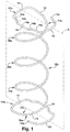
FIG. 1 is a perspective view of a Reverse Coil Head Coil according to the present invention; -
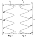
FIG. 2 is a side view of the Reverse Coil Head Coil ofFIG. 1 ; -
FIG. 3 is the opposite side view of the Reverse Coil Head Coil ofFIG. 2 ; -
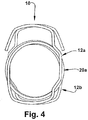
FIG. 4 is a top view of the Reverse Coil Head Coil ofFIG. 1 ; -
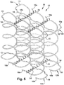
FIG. 5 is a perspective of an innerspring assembled with the Reverse Coil Head Coil ofFIG. 1 , and -
FIG. 6 is an elevation of an alternate embodiment of a Reverse Coil Head Coil of the present disclosure. - As shown in the Figures, a reverse coil head coil (hereinafter referred to as "RCH coil" or "coil") of the present disclosure and related inventions is indicated in its entirety at
reference numeral 10. TheRCH coil 10 has a generally helical andcylindrical body 12c formed by a plurality of generally helical turns, such as 20a, 20b and 20c. Thecoil body 12c is connected torespective coil ends coil ends FIG. 1 , eachcoil end coil body 12c these segments of the coil ends are referred to as "offsets", which facilitate inter-engagement between the coils, such as for example by a helical lacing wire which wraps around the offsets of adjacent coils to lace them together, as shown for example inFIG. 5 . As noted, in the coils of the present disclosure, the opposing coil ends are out of phase and generally diametrically opposed or 180 degrees out of phase with respect to a reference plane A through the body of the coil, as shown inFIG. 1 . - The
coil body 12c has a longitudinal axis which runs the length of the coil at the radial center of each of the helical turns of the coil. The coil body is contiguous with a first coil end, generally indicated at 12a, and a second coil end, generally indicated at 12b. The designations "first coil end" and "second coil end" are for identification and reference only and do not otherwise define the locations or orientations of the coil ends. Accordingly, either thefirst coil end 12a or thesecond coil end 12b may alternatively be referred to herein as a "coil end". Either of thecoil ends coil ends coil ends coil ends - The
coil ends Terminal ends FIG. 1 , on eachcoil end first offset 13 which is generally linear connected to asecond offset 14 which is also generally linear but which includes multiple connecting or transition orstepped segments terminal offset 15, from which the respective terminal ends 15a, 15b extend. Eachterminal offset 15 has a free orterminal end 15a which is turned to extend generally perpendicularly from theterminal offset 15, or generally parallel tosecond offset 14. Theterminal end 15a preferably does not extend past the center of the coil to avoid interference with the first convolution of the coil body and prevent a clicking sound or other noise relating to interference with the same or adjacent coils. Preferably, the offset portions are not in the generally helical form of thecoil body 12c. Theoffsets coil body 12c. The coil ends 12a and 12b of this general configuration are advantageous for allowing the coils to be closely arranged in an innerspring array than coils with circular ends, and provide a generally linear path for lacing wires that run between and interconnect the coils, as shown inFIG. 5 . The coils are positioned in the innerspring matrix such that thefirst offsets 13overlap terminal offsets 15 of the adjacent coils. As further shown inFIG. 5 , the overlapped offsets are connected together by a lacingwire 34 to interconnect entire rows of adjacent coils to form aninnerspring 30. The connectedoffsets - The
first offset 13 extends from a transition or connectingsegment 16 which connects thecoil ends coil body 12c. The integral connection of the connectingsegment 16 and thecoil body 12c is at a transition angle from thehelical coil body 12c which forms agradient arm 16a, in the general region indicated, which alters the spring rate of the coil under different types of loads. The compression of the coil, and thus the firmness of the coil, can be adjusted within limits by varying the length and angle of thegradient arm 16a relative to thecoil body 12c andcoil end gradient arm 16 adds extra support when a load is applied to the coil, as described inU.S. 4,726,572 . - A preferred embodiment of the RCH coils of the present disclosure is made from a single piece of wire which is first given a spiral shape and then formed with the desired coil ends or terminal convolutions. In a preferred embodiment, the wire stock is for example, such as 14.25 gauge wire with a tensile strength between 235,000 and 255,000 psi. The coil has an approximate overall axial length in a range of about 6.0 inches to 6.5 inches with approximately 4.75 turns or revolutions. The
center convolution 20b has a slightly smaller pitch and diameter measurements than the twoconvolutions center convolution 20b has both a pitch and a diameter of approximately 44 mm. The twoconvolutions free end 15b is approximately 15 mm. -
FIG. 5 illustrates a portion of an innerspring 30 in which a plurality of RCH coils 10 are connected together by lacingwires 34 are engaged with the respective ends 12a and 12b of the coils, and more particularly engaged with thefirst offsets 13 of the coils ends and the terminal offsets 15 of the coils ends of adjacent coils, and vice versa, and wherein the respective terminal ends 15a and 15b are consistently oriented within the innerspring. In this view it is apparent that the coil ends 15a are commonly oriented toward one side of the innerspring, and coil ends 15b are commonly located toward an opposite side of the innerspring and generally diametrically opposed to coil ends 15a. As further shown inFIG. 5 , a perimeter of themattress innerspring 30 is formed by the reverse coil head coils located at the perimeter or sides of the innerspring (right and left sides and the head and foot end sides), with the terminal ends 15b of the second coil ends 12b located at the perimeter of one side of the innerspring 30 and more particularly at an edge of the perimeter of the innerspring 30, and the terminal ends 15a of the first coil ends 12a located inboard of the perimeter of one side of the innerspring 30, wherein the perimeter of the innerspring 30 is defined by the outmost region of the coils along the sides of the innerspring 30. At the opposite side of the innerspring perimeter, the terminal ends 15a of the first coil ends 12a are located at the perimeter of the innerspring, and the terminal ends 15b of second coil ends 12b are located inboard of the perimeter. For the other two sides of the perimeter of the innerspring, one is formed byterminal offsets 15, and the other byfirst offsets 13. Of course these orientations can be reversed by inversion of the innerspring 30. In the example shown inFIG. 5 , the terminal ends 15b are located at one longitudinal perimeter of the innerspring, and terminal ends 15a are located at an opposite longitudinal perimeter of the innerspring, andterminal offsets 15 are located at one transverse perimeter of the innerspring (for example the head or foot end of a mattress innerspring) andfirst offsets 13 are located at an opposite transverse perimeter of the innerspring. -
FIG. 6 illustrates an alternate embodiment of anRCH coil 10 of the present disclosure wherein thecoil body 12c has pitch angles or vertical spacing between the helical turns of the coil. Approximate exemplary dimensions may be, for example: pitch spacing A may be 20mm, pitch B 15mm, pitch C 37mm, pitch D 39mm, pitch E 37mm and pitch F 15mm, for an approximate total coil height CH of 160mm-165mm. The smaller pitch dimensions create a smaller spring rate which provides the coil with a soft initial feel or easier compression at that end of the coil which is graduated to a higher spring rate toward the middle range of the coil body and to the base. Thecoil bodies 12c of the RCH coils can be made the same as or similar to the coils disclosed in the commonly assignedU.S. Patent No. 7,178,187 . The described axial alignment properties of theRCH coil 10 work equally well with these types of asymmetric coil designs. - It will be appreciated by persons skilled in the art that numerous variations and/or modifications may be made to the invention as shown in the specific embodiments without departing from the scope of the invention as broadly described. The present embodiments are, therefore, to be considered in all respects as illustrative and not restrictive. Other features and aspects of this invention will be appreciated by those skilled in the art upon reading and comprehending this disclosure. Such features, aspects, and expected variations and modifications of the reported results and examples are clearly within the scope of the invention where the invention is limited solely by the scope of the following claims.
Claims (14)
- A mattress innerspring (30) comprising a plurality of interconnected reverse coil head coils (10), each reverse coil head coil having:a generally helical coil body (12c) with a plurality of generally helical turns of wire (20a, 20b, 20c);a first coil end (12a) contiguous with a first end of the coil body and substantially lying in a plane which is generally perpendicular to an axis of the coil body (12c);a second coil end (12b) contiguous with a second end of the coil body and substantially lying in a plane which is generally perpendicular to the axis of the coil body (12c);each coil end (12a, 12b) comprising a first offset (13), a second offset (14), a terminal offset (15), and a terminal end (15a, 15b) which extends from terminal offset (15), wherein the offsets (13, 14, 15) are segments of the coil ends (12a, 12b) being formed to extend partially or entirely outside of the diameter of the coil body (12c);the first coil end (12a) having the terminal end (15a) which is located on a first side of a reference plane (A) which passes through the coil body (12c);and the second offset (14) which is located entirety on a second side of the reference plane (A) which passes through the coil body (12c);the second coil end (12b) having the terminal end (15b) which is located on the second side the reference plane (A) which passes through the coil body (12c);and the second offset (14) which is located entirely on the first side of the reference plane (A) which passes through the coil body (12c);the plurality of reverse coil head coils (10) being arranged in a matrix wherein the axes of the coils are generally parallel and the first coil ends (12a) are generally co-planar and the second coil ends (12b) are generally co-planar, the first coil ends of adjacent coils being laced together by a lacing wire (34), the lacing wire (34) engaged with an offset of the first coil end (12a) of a coil and engaged with a terminal offset (15) of the first coil end (12a) of an adjacent coil,and the second coil ends (12b) of adjacent coils being laced together by a lacing wire (34), the lacing wire (34) engaged with an offset of the second coil end (12b) of a coil and engaged with a terminal offset (15) of the second coil end (12b) of an adjacent coil, characterized inthat the second offset (14) of the coil ends (12a, 12b) has a stepped segment defined by connecting segments (14c) and transition segments (14b) and a stepped segment (14a) located between the connecting and transition segments (14b, 14c).
- The mattress innerspring (30) of claim 1, wherein each of the reverse coil head coils has at least three turns in the coil body.
- The mattress innerspring (30) of claim 2, wherein a pitch and diameter of at least one helical turn (20b) located in a middle region of the coil body (12c) is less than the pitch and diameter of other helical turns (20a, 20c) of the coil body (12c) which are relatively closer to the first or second coil ends (12a, 12b).
- The mattress innerspring (30) of claim 3, wherein the helical turn (20b) of the reverse coil head coils (10) located in the middle region of the coil body has a pitch in an approximate range of 38 mm to 44 mm.
- The mattress innerspring (30) of any of claims 3 or 4, wherein the helical turn (20b) of the reverse coil head coils (10) located in a middle region of the coil body (12c) has a diameter of approximately 44 mm.
- The mattress innerspring (30) of claim 3, wherein a coil height of the reverse coil head coils (10) in an uncompressed state is in an approximate range of 100 mm to 125 mm.
- The mattress innerspring (30) of claim 3, wherein the coil body (12c) has at least four or more helical turns.
- The mattress innerspring (30) of claim 3, wherein the first and second coil ends (12a, 12b) of the reverse coil head coils (10) have a generally rectangular shape.
- The mattress innerspring (30) of claim 1, wherein the coil body (12c) has at least four helical convolutions and at least two different pitch angles between the helical convolutions.
- The mattress innerspring (30) of any of claims 1, 3 and 9, wherein the wire coils are made of 14.25 gauge wire with a tensile strength between 235,000 and 255,000 psi.
- The mattress innerspring (30) of claim 9, wherein perimeter coils of the innerspring are unattached to a border wire.
- The mattress innerspring (30) of claim 3 or 9, wherein the coil body (12c) contains approximately 4.75 convolutions.
- The mattress innerspring (30) of claim 3 or 9, wherein a center convolution of each coil has a smaller diameter and pitch than the other convolutions.
- The mattress innerspring (30) of claim 3 or 9, wherein the terminal end (15a, 15b) of the first and second coil ends (12a, 12b) of each coil has a length dimension of approximately 15 mm.
Priority Applications (1)
| Application Number | Priority Date | Filing Date | Title |
|---|---|---|---|
| PL12736960T PL2665392T3 (en) | 2011-01-20 | 2012-01-16 | Reverse coil head coils and innersprings |
Applications Claiming Priority (2)
| Application Number | Priority Date | Filing Date | Title |
|---|---|---|---|
| US13/010,525 US9022369B2 (en) | 2011-01-20 | 2011-01-20 | Reverse coil head coils and innersprings |
| PCT/US2012/021414 WO2012099812A1 (en) | 2011-01-20 | 2012-01-16 | Reverse coil head coils and innersprings |
Publications (3)
| Publication Number | Publication Date |
|---|---|
| EP2665392A1 EP2665392A1 (en) | 2013-11-27 |
| EP2665392A4 EP2665392A4 (en) | 2014-06-25 |
| EP2665392B1 true EP2665392B1 (en) | 2018-11-21 |
Family
ID=46516029
Family Applications (1)
| Application Number | Title | Priority Date | Filing Date |
|---|---|---|---|
| EP12736960.1A Active EP2665392B1 (en) | 2011-01-20 | 2012-01-16 | Reverse coil head coils and innersprings |
Country Status (16)
| Country | Link |
|---|---|
| US (1) | US9022369B2 (en) |
| EP (1) | EP2665392B1 (en) |
| JP (1) | JP2014506490A (en) |
| KR (2) | KR102090031B1 (en) |
| CN (1) | CN103327851A (en) |
| AU (1) | AU2012207475B2 (en) |
| BR (1) | BR112013018279B1 (en) |
| CA (1) | CA2825044C (en) |
| DK (1) | DK2665392T3 (en) |
| ES (1) | ES2703511T3 (en) |
| IL (1) | IL227503A0 (en) |
| MX (1) | MX2013008403A (en) |
| PL (1) | PL2665392T3 (en) |
| SG (1) | SG192053A1 (en) |
| WO (1) | WO2012099812A1 (en) |
| ZA (1) | ZA201305423B (en) |
Families Citing this family (20)
| Publication number | Priority date | Publication date | Assignee | Title |
|---|---|---|---|---|
| USD675856S1 (en) | 2010-07-02 | 2013-02-12 | Nomaco Inc. | Foam support with coil enclosures for use in a mattress or a cushion |
| USD739162S1 (en) * | 2012-08-22 | 2015-09-22 | L&P Swiss Holding Ag | Coil spring |
| PL2719307T3 (en) * | 2012-10-11 | 2016-10-31 | Spring, spring core unit and method of producing a spring core unit | |
| CN105377082A (en) * | 2013-03-14 | 2016-03-02 | 丝涟科技有限责任公司 | Encased asymmetric coil innersprings with alternating coil spring orientations |
| US20220007847A9 (en) * | 2013-09-25 | 2022-01-13 | Yoo Soo Ahn | High tension coil spring structure for bed mattress having means for preventing friction noise |
| US11076705B2 (en) | 2014-05-30 | 2021-08-03 | Sealy Technology, Llc | Spring core with integrated cushioning layer |
| DK3389450T3 (en) | 2015-12-17 | 2024-06-03 | Sealy Technology Llc | Coil-in-coil spring with variable load ratio and mattresses including one |
| MX2018008961A (en) | 2016-01-21 | 2019-05-06 | Sealy Technology Llc | Coil-in-coil springs with non-linear loading responses and mattresses including the same. |
| DK3554315T3 (en) | 2016-12-15 | 2025-10-06 | Sealy Technology Llc | Open coil spring devices |
| USD825974S1 (en) * | 2017-03-20 | 2018-08-21 | L&P Property Management Company | Continuous spring |
| WO2019057264A1 (en) * | 2017-09-21 | 2019-03-28 | Wabco Europe Bvba | SLING SPRING AND SLAT SPRING ASSEMBLY |
| UA127787C2 (en) | 2017-10-31 | 2024-01-03 | Сілі Текнолоджи, Елелсі | Pocket coil spring assembly including flexible foam |
| AU2018407588B2 (en) * | 2018-02-09 | 2024-03-14 | Madad Pty Ltd | Wire coil and innerspring system |
| CN108930738A (en) * | 2018-10-02 | 2018-12-04 | 湖州杭佳弹簧有限公司 | Single load bearing spring |
| JP7148972B2 (en) * | 2019-01-11 | 2022-10-06 | 筑豊金網工業株式会社 | coupling coil |
| EP4231872A4 (en) | 2020-10-21 | 2024-11-27 | Black Jet Innovations, Inc. | Mobile device grip and stand |
| USD1064696S1 (en) * | 2022-09-07 | 2025-03-04 | Spühl Gmbh | Coil spring |
| US12680588B2 (en) | 2023-08-02 | 2026-07-14 | Sealy Technology Llc | Coil springs, pocketed coil springs assemblies, and mattresses including the same |
| KR102812766B1 (en) * | 2024-04-26 | 2025-05-28 | 주식회사 금성침대 | Mattress using offset springs |
| USD1130393S1 (en) | 2025-03-03 | 2026-06-16 | Jacob Epstein | Accessory for a mobile device |
Family Cites Families (21)
| Publication number | Priority date | Publication date | Assignee | Title |
|---|---|---|---|---|
| US3653082A (en) * | 1970-08-13 | 1972-04-04 | Sealy | Mattress spring unit construction |
| CH658778A5 (en) | 1982-06-28 | 1986-12-15 | Spuehl Ag | SPRING CORE FOR A MATTRESS. |
| US4726572A (en) | 1986-05-16 | 1988-02-23 | Sealy, Incorporated | Spring coil and spring assembly |
| US6354577B1 (en) | 1995-06-07 | 2002-03-12 | Sealy Technology Llc | Composite material spring modules with integrally formed attachment fittings |
| ES2236717T3 (en) | 1994-10-21 | 2005-07-16 | The Ohio Mattress Company Licensing And Components Group | CONSTRUCTION OF SPRINGS SPRINGS PROVIDED WITH FREE FINAL LOOP. |
| US6149143A (en) * | 1995-03-20 | 2000-11-21 | L&P Property Management Company | Spring structure for a mattress innerspring having coaxial coil units |
| JP3252368B2 (en) * | 1996-12-06 | 2002-02-04 | 日本ベッド製造株式会社 | mattress |
| US20040046297A1 (en) | 2002-09-10 | 2004-03-11 | Demoss Larry | High profile balable coils and innersprings |
| US7044454B2 (en) | 2004-04-23 | 2006-05-16 | Bedding Component Manufacturers (Proprietary) Limited | Mattress inner spring assembly |
| US7063309B2 (en) | 2004-08-18 | 2006-06-20 | Bedding Component Manufacturers (Proprietary) Limited | Mattress spring structure |
| US7178187B2 (en) | 2004-08-28 | 2007-02-20 | Sealy Technology Llc | Asymmetric spring components and innersprings for one-sided mattresses |
| US7404223B2 (en) * | 2004-08-28 | 2008-07-29 | Sealy Technology Llc | Innerspring coils and innersprings with non-helical segments |
| USD530120S1 (en) | 2005-06-09 | 2006-10-17 | L&P Property Management Company | End portion of a coil spring |
| US7386897B2 (en) | 2005-06-09 | 2008-06-17 | L&P Property Management Company | Bedding or seating product made with coil springs having unknotted end turns |
| USD527932S1 (en) | 2005-06-09 | 2006-09-12 | L&P Property Management Company | Top portion of a spring core |
| US7251847B2 (en) * | 2005-10-13 | 2007-08-07 | L&P Property Management Company | Continuous wire spring mattress or seating product and method of manufacture |
| US7578016B1 (en) * | 2007-11-07 | 2009-08-25 | Hickory Springs Manufacturing Company | One-sided innerspring assembly |
| US8230538B2 (en) * | 2008-01-18 | 2012-07-31 | Sealy Technology Llc | Mattress innerspring inserts and supports |
| USD652235S1 (en) | 2010-12-16 | 2012-01-17 | Sealy Technology Llc | Coil |
| USD651828S1 (en) | 2010-12-16 | 2012-01-10 | Sealy Technology Llc | Coil |
| USD652234S1 (en) | 2010-12-16 | 2012-01-17 | Sealy Technology Llc | Coil |
-
2011
- 2011-01-20 US US13/010,525 patent/US9022369B2/en active Active
-
2012
- 2012-01-16 MX MX2013008403A patent/MX2013008403A/en active IP Right Grant
- 2012-01-16 WO PCT/US2012/021414 patent/WO2012099812A1/en not_active Ceased
- 2012-01-16 BR BR112013018279-2A patent/BR112013018279B1/en active IP Right Grant
- 2012-01-16 ES ES12736960T patent/ES2703511T3/en active Active
- 2012-01-16 JP JP2013550515A patent/JP2014506490A/en active Pending
- 2012-01-16 EP EP12736960.1A patent/EP2665392B1/en active Active
- 2012-01-16 CA CA2825044A patent/CA2825044C/en active Active
- 2012-01-16 PL PL12736960T patent/PL2665392T3/en unknown
- 2012-01-16 AU AU2012207475A patent/AU2012207475B2/en active Active
- 2012-01-16 CN CN2012800061447A patent/CN103327851A/en active Pending
- 2012-01-16 KR KR1020197032722A patent/KR102090031B1/en active Active
- 2012-01-16 KR KR1020137021986A patent/KR20140032995A/en not_active Ceased
- 2012-01-16 DK DK12736960.1T patent/DK2665392T3/en active
- 2012-01-16 SG SG2013055389A patent/SG192053A1/en unknown
-
2013
- 2013-07-16 IL IL227503A patent/IL227503A0/en active IP Right Grant
- 2013-07-18 ZA ZA2013/05423A patent/ZA201305423B/en unknown
Non-Patent Citations (1)
| Title |
|---|
| None * |
Also Published As
| Publication number | Publication date |
|---|---|
| ES2703511T3 (en) | 2019-03-11 |
| CA2825044A1 (en) | 2012-07-26 |
| KR20190132495A (en) | 2019-11-27 |
| DK2665392T3 (en) | 2019-03-11 |
| EP2665392A1 (en) | 2013-11-27 |
| PL2665392T3 (en) | 2019-05-31 |
| SG192053A1 (en) | 2013-08-30 |
| CA2825044C (en) | 2019-01-15 |
| KR20140032995A (en) | 2014-03-17 |
| ZA201305423B (en) | 2014-09-25 |
| KR102090031B1 (en) | 2020-03-18 |
| IL227503A0 (en) | 2013-09-30 |
| US9022369B2 (en) | 2015-05-05 |
| AU2012207475B2 (en) | 2016-10-20 |
| BR112013018279A2 (en) | 2016-11-16 |
| BR112013018279B1 (en) | 2021-03-09 |
| CN103327851A (en) | 2013-09-25 |
| JP2014506490A (en) | 2014-03-17 |
| US20120186026A1 (en) | 2012-07-26 |
| EP2665392A4 (en) | 2014-06-25 |
| MX2013008403A (en) | 2013-10-17 |
| WO2012099812A1 (en) | 2012-07-26 |
Similar Documents
| Publication | Publication Date | Title |
|---|---|---|
| US9022369B2 (en) | Reverse coil head coils and innersprings | |
| AU2012207475A1 (en) | Reverse coil head coils and innersprings | |
| US8720872B2 (en) | Innersprings with alternating coil spring orientations | |
| US7921561B2 (en) | Bedding or seating product made with coil springs having unknotted end turns with bumps | |
| US20200217384A1 (en) | Coil springs with non-linear loading responses and mattresses including the same | |
| AU2008219052B2 (en) | Innerspring coils and innersprings with non-helical segments | |
| US20120000018A1 (en) | Posture channel supports | |
| CA2820219C (en) | Mattress innerspring inserts and supports | |
| US20090193591A1 (en) | Variable coil density anisotropic innersprings | |
| US20130031726A1 (en) | Encased hourglass coils and mattress cores | |
| EP2689695B1 (en) | Spring core | |
| HK1216829A1 (en) | Coil-in-coil springs and innersprings | |
| US6339857B1 (en) | Spring arrangement for mattresses |
Legal Events
| Date | Code | Title | Description |
|---|---|---|---|
| PUAI | Public reference made under article 153(3) epc to a published international application that has entered the european phase |
Free format text: ORIGINAL CODE: 0009012 |
|
| 17P | Request for examination filed |
Effective date: 20130816 |
|
| AK | Designated contracting states |
Kind code of ref document: A1 Designated state(s): AL AT BE BG CH CY CZ DE DK EE ES FI FR GB GR HR HU IE IS IT LI LT LU LV MC MK MT NL NO PL PT RO RS SE SI SK SM TR |
|
| REG | Reference to a national code |
Ref country code: HK Ref legal event code: DE Ref document number: 1186638 Country of ref document: HK |
|
| DAX | Request for extension of the european patent (deleted) | ||
| A4 | Supplementary search report drawn up and despatched |
Effective date: 20140526 |
|
| RIC1 | Information provided on ipc code assigned before grant |
Ipc: A47C 23/04 20060101AFI20140520BHEP Ipc: A47C 27/06 20060101ALI20140520BHEP Ipc: A47C 23/043 20060101ALI20140520BHEP Ipc: A47C 27/07 20060101ALI20140520BHEP Ipc: A47C 23/053 20060101ALI20140520BHEP |
|
| 17Q | First examination report despatched |
Effective date: 20151111 |
|
| STAA | Information on the status of an ep patent application or granted ep patent |
Free format text: STATUS: EXAMINATION IS IN PROGRESS |
|
| GRAP | Despatch of communication of intention to grant a patent |
Free format text: ORIGINAL CODE: EPIDOSNIGR1 |
|
| STAA | Information on the status of an ep patent application or granted ep patent |
Free format text: STATUS: GRANT OF PATENT IS INTENDED |
|
| INTG | Intention to grant announced |
Effective date: 20180614 |
|
| GRAS | Grant fee paid |
Free format text: ORIGINAL CODE: EPIDOSNIGR3 |
|
| GRAA | (expected) grant |
Free format text: ORIGINAL CODE: 0009210 |
|
| STAA | Information on the status of an ep patent application or granted ep patent |
Free format text: STATUS: THE PATENT HAS BEEN GRANTED |
|
| AK | Designated contracting states |
Kind code of ref document: B1 Designated state(s): AL AT BE BG CH CY CZ DE DK EE ES FI FR GB GR HR HU IE IS IT LI LT LU LV MC MK MT NL NO PL PT RO RS SE SI SK SM TR |
|
| REG | Reference to a national code |
Ref country code: CH Ref legal event code: EP |
|
| REG | Reference to a national code |
Ref country code: IE Ref legal event code: FG4D |
|
| REG | Reference to a national code |
Ref country code: DE Ref legal event code: R096 Ref document number: 602012053790 Country of ref document: DE |
|
| REG | Reference to a national code |
Ref country code: AT Ref legal event code: REF Ref document number: 1066517 Country of ref document: AT Kind code of ref document: T Effective date: 20181215 |
|
| REG | Reference to a national code |
Ref country code: ES Ref legal event code: FG2A Ref document number: 2703511 Country of ref document: ES Kind code of ref document: T3 Effective date: 20190311 Ref country code: DK Ref legal event code: T3 Effective date: 20190304 |
|
| REG | Reference to a national code |
Ref country code: NL Ref legal event code: MP Effective date: 20181121 |
|
| REG | Reference to a national code |
Ref country code: AT Ref legal event code: MK05 Ref document number: 1066517 Country of ref document: AT Kind code of ref document: T Effective date: 20181121 |
|
| PG25 | Lapsed in a contracting state [announced via postgrant information from national office to epo] |
Ref country code: NO Free format text: LAPSE BECAUSE OF FAILURE TO SUBMIT A TRANSLATION OF THE DESCRIPTION OR TO PAY THE FEE WITHIN THE PRESCRIBED TIME-LIMIT Effective date: 20190221 Ref country code: BG Free format text: LAPSE BECAUSE OF FAILURE TO SUBMIT A TRANSLATION OF THE DESCRIPTION OR TO PAY THE FEE WITHIN THE PRESCRIBED TIME-LIMIT Effective date: 20190221 Ref country code: FI Free format text: LAPSE BECAUSE OF FAILURE TO SUBMIT A TRANSLATION OF THE DESCRIPTION OR TO PAY THE FEE WITHIN THE PRESCRIBED TIME-LIMIT Effective date: 20181121 Ref country code: IS Free format text: LAPSE BECAUSE OF FAILURE TO SUBMIT A TRANSLATION OF THE DESCRIPTION OR TO PAY THE FEE WITHIN THE PRESCRIBED TIME-LIMIT Effective date: 20190321 Ref country code: LT Free format text: LAPSE BECAUSE OF FAILURE TO SUBMIT A TRANSLATION OF THE DESCRIPTION OR TO PAY THE FEE WITHIN THE PRESCRIBED TIME-LIMIT Effective date: 20181121 Ref country code: AT Free format text: LAPSE BECAUSE OF FAILURE TO SUBMIT A TRANSLATION OF THE DESCRIPTION OR TO PAY THE FEE WITHIN THE PRESCRIBED TIME-LIMIT Effective date: 20181121 Ref country code: LV Free format text: LAPSE BECAUSE OF FAILURE TO SUBMIT A TRANSLATION OF THE DESCRIPTION OR TO PAY THE FEE WITHIN THE PRESCRIBED TIME-LIMIT Effective date: 20181121 Ref country code: HR Free format text: LAPSE BECAUSE OF FAILURE TO SUBMIT A TRANSLATION OF THE DESCRIPTION OR TO PAY THE FEE WITHIN THE PRESCRIBED TIME-LIMIT Effective date: 20181121 |
|
| PG25 | Lapsed in a contracting state [announced via postgrant information from national office to epo] |
Ref country code: SE Free format text: LAPSE BECAUSE OF FAILURE TO SUBMIT A TRANSLATION OF THE DESCRIPTION OR TO PAY THE FEE WITHIN THE PRESCRIBED TIME-LIMIT Effective date: 20181121 Ref country code: AL Free format text: LAPSE BECAUSE OF FAILURE TO SUBMIT A TRANSLATION OF THE DESCRIPTION OR TO PAY THE FEE WITHIN THE PRESCRIBED TIME-LIMIT Effective date: 20181121 Ref country code: NL Free format text: LAPSE BECAUSE OF FAILURE TO SUBMIT A TRANSLATION OF THE DESCRIPTION OR TO PAY THE FEE WITHIN THE PRESCRIBED TIME-LIMIT Effective date: 20181121 Ref country code: GR Free format text: LAPSE BECAUSE OF FAILURE TO SUBMIT A TRANSLATION OF THE DESCRIPTION OR TO PAY THE FEE WITHIN THE PRESCRIBED TIME-LIMIT Effective date: 20190222 Ref country code: PT Free format text: LAPSE BECAUSE OF FAILURE TO SUBMIT A TRANSLATION OF THE DESCRIPTION OR TO PAY THE FEE WITHIN THE PRESCRIBED TIME-LIMIT Effective date: 20190321 Ref country code: RS Free format text: LAPSE BECAUSE OF FAILURE TO SUBMIT A TRANSLATION OF THE DESCRIPTION OR TO PAY THE FEE WITHIN THE PRESCRIBED TIME-LIMIT Effective date: 20181121 |
|
| PG25 | Lapsed in a contracting state [announced via postgrant information from national office to epo] |
Ref country code: CZ Free format text: LAPSE BECAUSE OF FAILURE TO SUBMIT A TRANSLATION OF THE DESCRIPTION OR TO PAY THE FEE WITHIN THE PRESCRIBED TIME-LIMIT Effective date: 20181121 Ref country code: IT Free format text: LAPSE BECAUSE OF FAILURE TO SUBMIT A TRANSLATION OF THE DESCRIPTION OR TO PAY THE FEE WITHIN THE PRESCRIBED TIME-LIMIT Effective date: 20181121 |
|
| REG | Reference to a national code |
Ref country code: DE Ref legal event code: R097 Ref document number: 602012053790 Country of ref document: DE |
|
| PG25 | Lapsed in a contracting state [announced via postgrant information from national office to epo] |
Ref country code: MC Free format text: LAPSE BECAUSE OF FAILURE TO SUBMIT A TRANSLATION OF THE DESCRIPTION OR TO PAY THE FEE WITHIN THE PRESCRIBED TIME-LIMIT Effective date: 20181121 Ref country code: RO Free format text: LAPSE BECAUSE OF FAILURE TO SUBMIT A TRANSLATION OF THE DESCRIPTION OR TO PAY THE FEE WITHIN THE PRESCRIBED TIME-LIMIT Effective date: 20181121 Ref country code: EE Free format text: LAPSE BECAUSE OF FAILURE TO SUBMIT A TRANSLATION OF THE DESCRIPTION OR TO PAY THE FEE WITHIN THE PRESCRIBED TIME-LIMIT Effective date: 20181121 Ref country code: SM Free format text: LAPSE BECAUSE OF FAILURE TO SUBMIT A TRANSLATION OF THE DESCRIPTION OR TO PAY THE FEE WITHIN THE PRESCRIBED TIME-LIMIT Effective date: 20181121 Ref country code: SK Free format text: LAPSE BECAUSE OF FAILURE TO SUBMIT A TRANSLATION OF THE DESCRIPTION OR TO PAY THE FEE WITHIN THE PRESCRIBED TIME-LIMIT Effective date: 20181121 |
|
| REG | Reference to a national code |
Ref country code: CH Ref legal event code: PL |
|
| PLBE | No opposition filed within time limit |
Free format text: ORIGINAL CODE: 0009261 |
|
| STAA | Information on the status of an ep patent application or granted ep patent |
Free format text: STATUS: NO OPPOSITION FILED WITHIN TIME LIMIT |
|
| PG25 | Lapsed in a contracting state [announced via postgrant information from national office to epo] |
Ref country code: LU Free format text: LAPSE BECAUSE OF NON-PAYMENT OF DUE FEES Effective date: 20190116 |
|
| REG | Reference to a national code |
Ref country code: BE Ref legal event code: MM Effective date: 20190131 |
|
| 26N | No opposition filed |
Effective date: 20190822 |
|
| REG | Reference to a national code |
Ref country code: IE Ref legal event code: MM4A |
|
| PG25 | Lapsed in a contracting state [announced via postgrant information from national office to epo] |
Ref country code: SI Free format text: LAPSE BECAUSE OF FAILURE TO SUBMIT A TRANSLATION OF THE DESCRIPTION OR TO PAY THE FEE WITHIN THE PRESCRIBED TIME-LIMIT Effective date: 20181121 |
|
| PG25 | Lapsed in a contracting state [announced via postgrant information from national office to epo] |
Ref country code: BE Free format text: LAPSE BECAUSE OF NON-PAYMENT OF DUE FEES Effective date: 20190131 |
|
| PG25 | Lapsed in a contracting state [announced via postgrant information from national office to epo] |
Ref country code: LI Free format text: LAPSE BECAUSE OF NON-PAYMENT OF DUE FEES Effective date: 20190131 Ref country code: CH Free format text: LAPSE BECAUSE OF NON-PAYMENT OF DUE FEES Effective date: 20190131 |
|
| PG25 | Lapsed in a contracting state [announced via postgrant information from national office to epo] |
Ref country code: IE Free format text: LAPSE BECAUSE OF NON-PAYMENT OF DUE FEES Effective date: 20190116 |
|
| PG25 | Lapsed in a contracting state [announced via postgrant information from national office to epo] |
Ref country code: TR Free format text: LAPSE BECAUSE OF FAILURE TO SUBMIT A TRANSLATION OF THE DESCRIPTION OR TO PAY THE FEE WITHIN THE PRESCRIBED TIME-LIMIT Effective date: 20181121 |
|
| PG25 | Lapsed in a contracting state [announced via postgrant information from national office to epo] |
Ref country code: MT Free format text: LAPSE BECAUSE OF NON-PAYMENT OF DUE FEES Effective date: 20190116 |
|
| PG25 | Lapsed in a contracting state [announced via postgrant information from national office to epo] |
Ref country code: CY Free format text: LAPSE BECAUSE OF FAILURE TO SUBMIT A TRANSLATION OF THE DESCRIPTION OR TO PAY THE FEE WITHIN THE PRESCRIBED TIME-LIMIT Effective date: 20181121 |
|
| PG25 | Lapsed in a contracting state [announced via postgrant information from national office to epo] |
Ref country code: HU Free format text: LAPSE BECAUSE OF FAILURE TO SUBMIT A TRANSLATION OF THE DESCRIPTION OR TO PAY THE FEE WITHIN THE PRESCRIBED TIME-LIMIT; INVALID AB INITIO Effective date: 20120116 |
|
| PG25 | Lapsed in a contracting state [announced via postgrant information from national office to epo] |
Ref country code: MK Free format text: LAPSE BECAUSE OF FAILURE TO SUBMIT A TRANSLATION OF THE DESCRIPTION OR TO PAY THE FEE WITHIN THE PRESCRIBED TIME-LIMIT Effective date: 20181121 |
|
| P01 | Opt-out of the competence of the unified patent court (upc) registered |
Effective date: 20230524 |
|
| PGFP | Annual fee paid to national office [announced via postgrant information from national office to epo] |
Ref country code: GB Payment date: 20260121 Year of fee payment: 15 |
|
| PGFP | Annual fee paid to national office [announced via postgrant information from national office to epo] |
Ref country code: ES Payment date: 20260217 Year of fee payment: 15 |
|
| PGFP | Annual fee paid to national office [announced via postgrant information from national office to epo] |
Ref country code: DE Payment date: 20260120 Year of fee payment: 15 Ref country code: DK Payment date: 20260121 Year of fee payment: 15 |
|
| PGFP | Annual fee paid to national office [announced via postgrant information from national office to epo] |
Ref country code: FR Payment date: 20260116 Year of fee payment: 15 |
|
| PGFP | Annual fee paid to national office [announced via postgrant information from national office to epo] |
Ref country code: PL Payment date: 20260107 Year of fee payment: 15 |
|
| REG | Reference to a national code |
Ref country code: HK Ref legal event code: WD Ref document number: 1186638 Country of ref document: HK |