EP2665109A1 - Battery packs and systems including battery packs and electric apparatus - Google Patents
Battery packs and systems including battery packs and electric apparatus Download PDFInfo
- Publication number
- EP2665109A1 EP2665109A1 EP13167826.0A EP13167826A EP2665109A1 EP 2665109 A1 EP2665109 A1 EP 2665109A1 EP 13167826 A EP13167826 A EP 13167826A EP 2665109 A1 EP2665109 A1 EP 2665109A1
- Authority
- EP
- European Patent Office
- Prior art keywords
- section
- battery pack
- battery
- specific kind
- connection section
- Prior art date
- Legal status (The legal status is an assumption and is not a legal conclusion. Google has not performed a legal analysis and makes no representation as to the accuracy of the status listed.)
- Granted
Links
Images


Classifications
-
- H—ELECTRICITY
- H01—ELECTRIC ELEMENTS
- H01M—PROCESSES OR MEANS, e.g. BATTERIES, FOR THE DIRECT CONVERSION OF CHEMICAL ENERGY INTO ELECTRICAL ENERGY
- H01M50/00—Constructional details or processes of manufacture of the non-active parts of electrochemical cells other than fuel cells, e.g. hybrid cells
- H01M50/20—Mountings; Secondary casings or frames; Racks, modules or packs; Suspension devices; Shock absorbers; Transport or carrying devices; Holders
- H01M50/244—Secondary casings; Racks; Suspension devices; Carrying devices; Holders characterised by their mounting method
-
- H—ELECTRICITY
- H01—ELECTRIC ELEMENTS
- H01M—PROCESSES OR MEANS, e.g. BATTERIES, FOR THE DIRECT CONVERSION OF CHEMICAL ENERGY INTO ELECTRICAL ENERGY
- H01M50/00—Constructional details or processes of manufacture of the non-active parts of electrochemical cells other than fuel cells, e.g. hybrid cells
- H01M50/20—Mountings; Secondary casings or frames; Racks, modules or packs; Suspension devices; Shock absorbers; Transport or carrying devices; Holders
- H01M50/247—Mountings; Secondary casings or frames; Racks, modules or packs; Suspension devices; Shock absorbers; Transport or carrying devices; Holders specially adapted for portable devices, e.g. mobile phones, computers, hand tools or pacemakers
-
- H—ELECTRICITY
- H01—ELECTRIC ELEMENTS
- H01M—PROCESSES OR MEANS, e.g. BATTERIES, FOR THE DIRECT CONVERSION OF CHEMICAL ENERGY INTO ELECTRICAL ENERGY
- H01M2220/00—Batteries for particular applications
- H01M2220/30—Batteries in portable systems, e.g. mobile phone, laptop
-
- Y—GENERAL TAGGING OF NEW TECHNOLOGICAL DEVELOPMENTS; GENERAL TAGGING OF CROSS-SECTIONAL TECHNOLOGIES SPANNING OVER SEVERAL SECTIONS OF THE IPC; TECHNICAL SUBJECTS COVERED BY FORMER USPC CROSS-REFERENCE ART COLLECTIONS [XRACs] AND DIGESTS
- Y02—TECHNOLOGIES OR APPLICATIONS FOR MITIGATION OR ADAPTATION AGAINST CLIMATE CHANGE
- Y02E—REDUCTION OF GREENHOUSE GAS [GHG] EMISSIONS, RELATED TO ENERGY GENERATION, TRANSMISSION OR DISTRIBUTION
- Y02E60/00—Enabling technologies; Technologies with a potential or indirect contribution to GHG emissions mitigation
- Y02E60/10—Energy storage using batteries
Definitions
- the main connection section and the auxiliary connection section may be disposed at positions spaced apart from each other. With this arrangement, the weight of the battery pack can be efficiently supported at two different positions.
- the battery mount portion 20 of the electric tool 10 will be first described before describing the battery pack 30.
- the electric tool 10 may be a large electric tool having a grip portion 12 that can be grasped by a user.
- the grip portion 12 may have a lower end portion where the battery mount portion 20 is disposed for connection with the battery pack 30.
- the electric tool 10 will be also referred to as a large electric tool 10.
- a pair of rear-side slide rails 35 may be formed on the left side and the right side of the central portion (with respect to the forward and rearward directions) of the lid 34 and may extend in the forward and rearward directions.
- a pair of front-side slide rails 37 may be formed on the left side and the right side of the front portion of the lid 34 and may extend in the forward and rearward directions.
- Stepped portions 36 may be formed at the boundary positions between the front-side slide rails 37 and the rear-side slide rails 35.
- the lock lease button 39f may be exposed to the outside at an operation opening 34x formed in the front portion of the lid 34.
- the slide lock portion 39k may include a front portion having a front surface extending substantially vertically, and a rear portion that may have an inclined surface 39s for contacting a front end portion of the top plate 21 of the battery mount portion 20.
- a spring 39b may be disposed inside of the lid 34 in order to bias the hook 39 to move upward (see FIG. 5 ).
- the hook 39 may be normally held at an uppermost position by the biasing force of the spring 39b.
Landscapes
- Chemical & Material Sciences (AREA)
- Chemical Kinetics & Catalysis (AREA)
- Electrochemistry (AREA)
- General Chemical & Material Sciences (AREA)
- Life Sciences & Earth Sciences (AREA)
- Engineering & Computer Science (AREA)
- Biophysics (AREA)
- Computer Hardware Design (AREA)
- Battery Mounting, Suspending (AREA)
Abstract
Description
- This application claims priority to Japanese patent application serial number
2012-114189 - The present invention relates to battery packs that may be connected to battery mount portions of electric apparatus. The present invention also relates to systems including battery packs and electric apparatuses to which the battery packs are connected.
-
JP-A-2001-143678 battery pack 100 shown inFIGS. 13 and 14 . Thebattery pack 100 is designed for use as a power source of an electric tool. As shown inFIG. 13 , thebattery pack 100 includes left andright slide rails 103 disposed at the upper surface of ahousing 102 for connection with a battery mount portion 105 (seeFIG. 14 ) of the electric tool. Theslide rails 103 extend in a forward and rearward direction with respect to thebattery pack 100. As shown inFIG. 14 , each of theslide rails 103 includes arail body 103m and a laterally projectinglinear projection 103y protruding outward in a widthwise direction (leftward and rightward) by a given distance from the upper end of therail body 103m. In this way, each of theslide rails 103 has a substantially inverted L-shape cross-section. - As shown in
FIG. 14 , thebattery mount portion 105 of the electric tool has a pair ofvertical walls 106 at opposite ends in the widthwise direction. Arectangular groove 106m is formed in the inner wall of each of thevertical walls 106 and extends in the forward and rearward direction for fitting with thecorresponding slide rail 103 of thebattery pack 100. Therefore, thebattery pack 100 can be connected to the electric tool by initially fitting the laterally projectinglinear projections 103y of theslide rails 103 of thebattery pack 100 into therectangular grooves 106m of thebattery mount portion 105 of the electric tool. Afterwards, it can be accomplished by moving the electric tool and thebattery pack 100 to slide relative to each other in the forward and rearward direction. - A plurality of different types of electric tools may have standardized battery mount portions each configured to be similar to the
battery mount portion 105. Also, a plurality of different types of battery packs may have standardized slide rails each configured to be similar to theslide rails 103. In this way, a specific battery pack (e.g., the battery pack 100) can be shared with a plurality of electric tools. - However, in the case that a plurality of different types of battery packs have standardized
slide rails 103, even a small battery pack is necessary to have theslide rails 103 that are the same as those of a large battery pack. - The standardized
slide rails 103 may be too large for a small battery pack, leading to difficulties in reducing the size of the battery packs. - Therefore, there has been a need in the art for enabling a small battery pack having a standardized connection section with a reduced size.
- In one aspect according to the present teachings, a battery pack may have a main connection section and an auxiliary connection section. The main connection section may be connectable with a plurality of different kinds of electric apparatus including a specific kind of electric apparatus and a non-specific kind of electric apparatus. The auxiliary connection section may be connectable with only the specific kind of electric apparatus.
- Additional objects, features, and advantages, of the present invention will be readily understood after reading the following detailed description together with the claims and the accompanying drawings, in which:
-
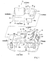
FIG 1 is a perspective view of a large battery pack and a battery mount portion of a large electric tool, to which the large battery pack is connected, according to a first embodiment; -
FIG. 2 is a perspective view showing the state where the large battery pack and the battery mount portion of the large electric tool have been connected to each other. -
FIG. 3 is a sectional view taken along line III-III inFIG. 2 ; -
FIG. 4 is a perspective view showing a cross-section a central portion of the battery mount portion of the large electric tool; -
FIG. 5 is a vertical sectional view showing the operation of a hook of the large battery pack; -
FIG. 6 is a perspective view showing the large battery pack and a battery mount portion of a small electric tool, to which the large battery pack is connected; -
FIG. 7 is a perspective view showing in cross section a central portion of the battery mount portion of the small electric tool; -
FIG. 8 is a perspective view showing the state where the large battery pack and the battery mount portion of the small electric tool have been connected to each other. -
FIG. 9 is a perspective view showing a small battery pack and the battery mount portion of the large electric tool, to which the small battery pack is connected; -
FIG. 10 is a perspective view showing a large battery pack and a battery mount portion of a small electric tool, to which the large battery pack is connected, according to a second embodiment; -
FIG. 11 is a perspective view showing the state where the large battery pack and the battery mount portion of the small electric tool have been connected to each other; -
FIG. 12 is a sectional view taken along line XII-XII inFIG. 11 ; -
FIG. 13 is a perspective view of a known battery pack; and -
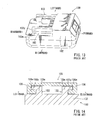
FIG. 14 is a sectional view showing the state where the known battery pack and a battery mount portion of an electric tool have been connected to each other. - Each of the additional features and teachings disclosed above and below may be utilized separately or in conjunction with other features and teachings to provide improved battery packs and electric apparatus systems. Representative examples of the present invention, which examples utilize many of these additional features and teachings both separately and in conjunction with one another, will now be described in detail with reference to the attached drawings. This detailed description is merely intended to teach a person of skill in the art further details for practicing preferred aspects of the present teachings and is not intended to limit the scope of the invention. Only the claims define the scope of the claimed invention. Therefore, combinations of features and steps disclosed in the following detailed description may not be necessary to practice the invention in the broadest sense, and are instead taught merely to particularly describe representative examples of the invention. Moreover, various features of the representative examples and the dependent claims may be combined in ways that are not specifically enumerated in order to provide additional useful examples of the present teachings. Various examples will now be described with reference to the drawings.
- In one embodiment, a battery pack may be connectable with battery mount portions of a plurality of different kinds of electric apparatuses. The battery pack may include a main connection section and an auxiliary connection section. The main connection section may be connectable with main connection complimentary sections of the battery mount portions of the different kinds of electric apparatuses as the main connection section is slid relative thereto. The auxiliary connection section may be connectable with an auxiliary connection complimentary section provided only on the battery mount portion of a specific kind of electric apparatus of the different kinds of electric apparatuses. The main connection section and the auxiliary connection section are configured such that the weight of the battery pack may be supported at the main connection section and the auxiliary connection section when the battery pack is connected to the battery mount portion of the specific kind of electric apparatus.
- With this arrangement, in the case where the main connection section used for connection with the battery mount portions of the different kinds of electric apparatuses is designed to have a small size, the weight of the battery pack can be securely supported with the aid of the auxiliary connection section even using a large battery pack having a weight that is relatively large.
- By designing the main connection section to be small in size in this way, it is possible to reduce the size of the battery pack. Incorporating the main connection section as a standardized connection section for different battery packs for connection with different kinds of electric apparatuses can be useful. One such embodiment may include a battery pack having only the main connection section. In such an embodiment, a battery pack having only the main connection section can be configured to have a small size.
- The main connection section and the auxiliary connection section may be disposed at positions spaced apart from each other. With this arrangement, the weight of the battery pack can be efficiently supported at two different positions.
- The auxiliary connection section may be connectable with the auxiliary connection complimentary section as the auxiliary connection section is slid relative to the auxiliary connection complimentary section.
- The main connection section may be connectable with the main connection complimentary section of the battery mount portion of the specific kind of electric apparatus as the main connection section is slid relative to the main connection complimentary section in a first sliding direction. On the other hand, the auxiliary connection section may be connectable with the auxiliary connection complimentary section of the battery mount portion of the specific kind of electric apparatus as the auxiliary connection section is slid relative to the auxiliary connection complimentary section in a second sliding direction that is the same as the first direction.
- The auxiliary connection complimentary section may include a projection. The auxiliary connection section may include an engaging portion engageable with the projection.
- The engaging portion may be disposed at a position determined such that the engaging portion engages the projection after the main connection section is slid in a direction relative to the main connection complimentary section of the battery mount portion of the specific kind of electric apparatus.
- The main connection section and the auxiliary connection section may be respectively connectable with the main connection complimentary section and the auxiliary connection complimentary section of the battery mount portion of the specific kind of electric apparatus. However, only the main connection section may be connectable with the main connection complimentary section of the battery mount portion of the other kinds of electric apparatuses other than the specific kind of electric apparatus.
- In another embodiment, a system may include different kinds of electric apparatuses each having a battery mount portion, and different kinds of battery packs connectable with the battery mount portions. The different kinds of electric apparatuses may include a specific kind of electric apparatus and a non-specific kind of electric apparatus. The different kinds of battery packs may include a specific kind of battery pack having a main connection section and an auxiliary connection section, and non-specific kind of battery pack having a main connection section and no auxiliary connection section. The battery mount portion of the specific kind of electric apparatus may include a main connection complimentary section and an auxiliary connection complimentary section. The main connection complimentary section of the battery mount portion of the specific kind of electric apparatus may be connectable with the different kinds of battery packs as the different kinds of battery packs are slid in a sliding direction relative to the main connection complimentary section. The auxiliary connection complimentary section of the battery mount portion of the specific kind of electric apparatus may be connectable with the auxiliary connection section of the specific kind of battery pack. The battery mount portion of the non-specific kind of electric apparatus may include a main connection complimentary section and no auxiliary connection complimentary section. The main connection complimentary section of the battery mount portion of the non-specific kind of electric apparatus may be connectable with the different kinds of battery packs as the different kinds of battery packs are slid in a sliding direction relative to the main connection complimentary section. The main connection section and the auxiliary connection section of the specific kind of battery pack may be configured such that the weight of the specific kind of battery pack can be supported at the main connection section and the auxiliary connection section when the specific kind of battery pack is connected to the battery mount portion of the specific kind of electric apparatus.
- In a further embodiment, a system may include a specific kind of electric apparatus having a battery mount portion, and different kinds of battery packs connectable with the battery mount portion. The different kinds of battery packs may include a specific kind of battery pack having a main connection section and an auxiliary connection section, and non-specific kind of battery pack having a main connection section and no auxiliary connection section. The battery mount portion of the specific kind of electric apparatus may include a main connection complimentary section and an auxiliary connection complimentary section. The main connection complimentary section of the battery mount portion of the specific kind of electric apparatus may be connectable with different kinds of battery packs as the different kinds of battery packs are slid in a sliding direction relative to the main connection complimentary section. The auxiliary connection complimentary section of the battery mount portion of the specific kind of electric apparatus may be connectable with the auxiliary connection section of the specific kind of battery pack. The main connection section and the auxiliary connection section of the specific kind of battery pack may be configured such that the weight of the specific kind of battery pack can be supported at the main connection section and the auxiliary connection section when the specific kind of battery pack is connected to the battery mount portion of the specific kind of electric apparatus. The main connection section of the non-specific kind of battery pack may be configured such that the weight of the non-specific kind of battery pack can be supported only at the main connection section when the non-specific kind of battery pack is connected to the battery mount portion of the specific kind of electric apparatus.
- An embodiment will now be described with reference to
FIGS. 1 to 9 . Abattery pack 30 can be used as a power source for driving an electric tool 10 (only a part is shown in the drawings). To this end, thebattery pack 30 can be removably connected to abattery mount portion 20 of theelectric tool 10. In the following description, forward, rearward, leftward, rightward, upward and downward directions are determined to correspond to those for thebattery pack 30 and theelectric tool 10. - The
battery mount portion 20 of theelectric tool 10 will be first described before describing thebattery pack 30. Theelectric tool 10 may be a large electric tool having agrip portion 12 that can be grasped by a user. Thegrip portion 12 may have a lower end portion where thebattery mount portion 20 is disposed for connection with thebattery pack 30. In the following description, theelectric tool 10 will be also referred to as a largeelectric tool 10. - As shown in
FIG. 1 , thebattery mount portion 20 may have a shape like a rectangular lid extending both in a widthwise direction (left and right direction) and a forward direction from the lower end portion of thegrip portion 12. Thebattery mount portion 20 may have a rectangulartop plate 21 and a fence-likevertical wall 22. Thevertical wall 22 may extend downward from the left and right edges and the rear edge of thetop plate 21. More specifically, thevertical wall 22 may have a substantially U-shape with its front side opened as seen in a plan view. Thevertical wall 22 may include a rearend wall portion 23, left and right rear-sidelateral wall portions 24 and left and right front-sidelateral wall portions 26. Steppedportions 25 may be formed at boundary positions between the rear-sidelateral wall portions 24 and the front-sidelateral wall portions 26, so that the distance between the front-sidelateral wall portions 26 may be larger than the distance between the rear-sidelateral wall portions 24 by a distance given by the steppedportions 25. - In this way, the left and right front-side
lateral wall portions 26 are positioned on the outer side with respect to the widthwise direction of the left and right rear-sidelateral wall portions 24. The length in the forward and rearward direction of the rear-sidelateral wall portions 24 may be longer than the length in the forward and rearward direction of the front-sidelateral wall portions 26. - The front-side
lateral wall portions 26 as well as the rear-sidelateral wall portions 24 may be symmetrical with respect to their right and left sides. As shown inFIG. 4 , a front-sidelinear projection 26f may be formed on the lower end portion of the inner surface of each of the front-sidelateral wall portions 26 to protrude inward therefrom by a given distance. A front-siderectangular groove 26m may be defined between the front-sidelinear projection 26f and thetop plate 21. Similarly, a rear-sidelinear projection 24b may be formed on the lower end portion of the inner surface of each of the rear-sidelateral wall portion 24 to protrude inward therefrom by a given distance. A rear-siderectangular groove 24x may be defined between the rear-sidelinear projection 24b and thetop plate 21. The steppedportion 25 may separate the rear-siderectangular groove 24x and the front-siderectangular groove 26m positioned on the same side (right side or left side), from each other (seeFIG. 4 ). - As shown in
FIGS. 4 and 5 , arectangular projection 21t having a hat-like cross-sectional configuration may be formed at the front portion of thetop plate 21. A hook-receiving steppedportion 21d may be defined at the front portion of the inner surface of therectangular projection 21t. - The
battery pack 30 may have a large storage capacity for supplying an electric power to the largeelectric tool 10. In the following description, thebattery pack 30 will be also referred to as alarge battery pack 30. - As shown in
FIG. 1 , thelarge battery pack 30 may include ahousing body 32 and alid 34. Thehousing body 32 may have an upper opening and may be configured to receive a plurality of battery cells (not shown). Thelid 34 may be configured to close the upper opening of thehousing body 32. - A pair of rear-side slide rails 35 may be formed on the left side and the right side of the central portion (with respect to the forward and rearward directions) of the
lid 34 and may extend in the forward and rearward directions. A pair of front-side slide rails 37 may be formed on the left side and the right side of the front portion of thelid 34 and may extend in the forward and rearward directions. Steppedportions 36 may be formed at the boundary positions between the front-side slide rails 37 and the rear-side slide rails 35. - The distance between the left and right front-side slide rails 37 may be set to conform to the distance between the left and right front-side
lateral wall portions 26 of thebattery mount portion 20 of the largeelectric tool 10. Similarly, the distance between the left and right rear-side slide rails 35 may be set to conform to the distance between the left and right rear-sidelateral wall portions 24 of thebattery mount portion 20. - In this way, the left and right front-side slide rails 37 may be positioned outward with respect to the widthwise direction of the left and right rear-side slide rails 35. In addition, the length in the forward and rearward directions of the rear-side slide rails 35 may be longer than the length in the forward and rearward directions of the front-side slide rails 37.
- As shown in
FIGS. 1 and3 , each of the rear-side slide rails 35 may include arail body 35m and a laterallinear projection 35y protruding outward in the widthwise direction (left and right direction) by a given distance from the upper end portion of therail body 35m. In this way, each of the rear-side slide rails 35 may have a substantially inverted L-shaped cross section. The laterallinear projections 35y of the rear-side slide rails 35 may be fitted into the rear-siderectangular grooves 24x of thebattery mount portion 20 of the largeelectric tool 10 so as to be slid relative thereto in the forward and rearward directions. - Similarly, as shown in
FIG. 1 , each of the front-side slide rails 37 may include arail body 37m and a laterallinear projection 37y protruding outward in the widthwise direction (left and right direction) by a given distance from the upper end portion of therail body 37m. The laterallinear projections 37y of the front-side slide rails 37 may be fitted into the front-siderectangular grooves 26m of thebattery mount portion 20 of the largeelectric tool 10 so as to be slid relative thereto in the forward and rearward directions. - A slit-
like opening 38 having a laterally facing U-shape in plan view may be formed in thelid 34 of thelarge battery pack 30 at a position between the left and right front-side slide rails 37. Ahook 39 may protrude outward from thelid 34 through the slit-like opening 38 for preventing the largeelectric tool 10 from being slid rearward beyond the hook 39 (i.e., from being removed from thelid 34 as a result of the rearward sliding movement). As shown inFIG. 1 , thehook 39 may include aslide lock portion 39k and alock release button 39f formed integrally with each other. Theslide lock portion 39k can protrude upward through the slit-like opening 38 of thelid 34. The lock lease button 39fmay be exposed to the outside at anoperation opening 34x formed in the front portion of thelid 34. Theslide lock portion 39k may include a front portion having a front surface extending substantially vertically, and a rear portion that may have aninclined surface 39s for contacting a front end portion of thetop plate 21 of thebattery mount portion 20. Aspring 39b may be disposed inside of thelid 34 in order to bias thehook 39 to move upward (seeFIG. 5 ). Thehook 39 may be normally held at an uppermost position by the biasing force of thespring 39b. The front surface of the front portion of theslide lock portion 39k may engage the hook receiving steppedportion 21d formed inside of therectangular projection 21t of thebattery mount portion 20, so that the sliding movement in the removing direction (rearward sliding movement) of the largeelectric tool 10 can be prevented. - As the
lock release button 39 is pressed to move thehook 39 downward against the biasing force of thespring 39b, theslide lock portion 39k may be disengaged from the hook receiving steppedportion 21d of thebattery mount portion 20 to enable the largeelectric tool 10 to slide in the removing direction (rearward direction). - In order to connect the
large battery pack 30 and the largeelectric tool 10, the largeelectric tool 10 may be moved horizontally forward from the rear side of thelarge battery pack 30, so that the front ends of the left and right rear-siderectangular grooves 24x of thebattery mount portion 20 of the largeelectric tool 10 are brought to be fitted with the rear ends of the left and right rear-side slide rails 35 of thelarge battery pack 30. Then, thebattery mount portion 20 of the largeelectric tool 10 may be pushed forward relative to thelarge battery pack 30, so that the left and right rear-side slide rails 35 and the left and right rear-siderectangular grooves 24x may slide relative to each other in the forward and rearward directions while they are fitted with each other. In the course of the forward sliding movement of thebattery mount portion 20 of the largeelectric tool 10 relative to thelarge battery pack 30, the front ends of the left and right front-siderectangular grooves 26m of thebattery mount portion 20 may be fitted with the rear ends of the left and right front-side slide rails 37 of thelarge battery pack 30. As thebattery mount portion 20 of the largeelectric tool 10 is pushed further forward relative to thelarge battery pack 30, the left and right front-side slide rails 37 and the left and right front-siderectangular grooves 26m as well as the left and right rear-side slide rails 35 and the left and right rear-siderectangular grooves 24x may slide relative to each other in the forward and rearward direction while they are fitted with each other. - In the course of the forward sliding movement of the
battery mount portion 20 of the largeelectric tool 10 relative to thelarge battery pack 30, thetop plate 21 of thebattery mount portion 20 may contact theinclined surface 39s of thehook 39 of thelarge battery pack 30 and may then be slid relative thereto, so that thehook 39 may be pressed downward against the biasing force of thespring 39b. When thebattery mount portion 20 of the largeelectric tool 10 has been slid forward relative to thelarge battery pack 30 to reach a connection completion position, therectangular projection 21t of thetop plate 21 of thebattery mount portion 20 may be positioned to be opposed to thehook 39, so that thehook 39 may protrude upward through the slit-like opening 38 by the biasing force of thespring 39b. Then, theslide lock portion 39k (more specifically, its front surface) may engage the hook receiving steppedportion 21d of thebattery mount portion 20, so that the largeelectric tool 10 may be prevented from being slid further in the removing direction (rearward sliding movement). - In addition, when the
battery mount portion 20 of the largeelectric tool 10 has been slid forward relative to thelarge battery pack 30 to reach the connection completion position, power source terminals and signal terminals (not shown) of the largeelectric tool 10 may be respectively electrically connected to power source terminals and signal terminals (not shown) of thelarge battery pack 30. - In this way, the
battery mount portion 20 of the largeelectric tool 10 and thelarge battery pack 30 may be connected to each other by way of fitting between the left and right rear-side slide rails 35 and the left and right rear-siderectangular groves 24x and also by way of fitting between the left and right front-side slide rails 37 and the left and right front-siderectangular grooves 26m. As a result, the weight of thelarge battery pack 30 that may be relatively large due to its large capacity may be supported in stable at two positions or at the rear-side slide rails 35 and the front-side slide rails 37. - The
large battery pack 30 may be connectable with a smallelectric tool 40 as shown inFIG. 6 . - A
battery mount portion 45 of the smallelectric tool 40 may be different from thebattery mount portion 20 of the largeelectric tool 10 in that the width of thebattery mount portion 45 is smaller than that of thebattery mount portion 20. In addition, thebattery mount portion 45 may be different from thebattery mount portion 20 in that thebattery mount portion 45 does not have the left and right front-sidelateral wall portions 26 nor the steppedportions 25. In other respect, thebattery mount portion 45 may be configured to be the same as thebattery mount portion 20. Therefore, inFIGS. 6 and7 , like members are given the same reference numerals as thebattery mount portion 20 and the description of these members will not be repeated. - Thus, as shown in
FIGS. 6 and7 , thebattery mount portion 45 may have avertical wall 22 having a substantially U-shape with its front side opened as seen in a plan view. Thevertical wall 22 may include a rearend wall portion 23 and left and right rear-sidelateral wall portions 24. The distance between the left and right rear-sidelateral wall portions 24 of thebattery mount portion 45 may be set to be equal to the distance between the left and right rear-sidelateral wall portions 24 of thebattery mount portion 20. - In order to connect the
large battery pack 30 and the smallelectric tool 40, the smallelectric tool 40 may be moved horizontally forward from the rear side of thelarge battery pack 30, so that the front ends of the left and right rear-siderectangular grooves 24x of thebattery mount portion 45 of the smallelectric tool 40 are brought to be fitted with the left and right rear-side slide rails 35 of thelarge battery pack 30. Then, the left and right rear-side slide rails 35 and the left and right rear-siderectangular grooves 24x may slide relative to each other in the forward and rearward directions while they are fitted with each other. In the course of the forward sliding movement of thebattery mount portion 45, thehook 39 may be pressed downward against the biasing force of thespring 39b as described previously. When thebattery mount portion 45 has reached a connection completion position, thehook 39 may protrude upward through the slit-like opening 38 by the biasing force of thespring 39b. Then, theslide lock portion 39k may engage the hook receiving steppedportion 21d of thebattery mount portion 45, so that thebattery mount portion 45 of the smallelectric tool 40 may be connected to thelarge battery pack 30 as shown inFIG. 8 . - A
small battery pack 50 shown inFIG. 9 may be typically used as a power source for thesmall power tool 40. InFIG. 9 , like members are given the same reference numerals as thelarge battery pack 30 and the description of these members will not be repeated. Thesmall battery pack 50 is different from thelarge battery pack 30 in that the housing size is smaller than that of thelarge battery pack 30 and that it only has left and right slide rails 35 that may be the same in the specification (standard) as the left and right rear-side slide rails 35 of thelarge battery pack 30. In other respect, thesmall battery pack 50 may be configured to be the same as thelarge battery pack 30. - In order to connect the small
electric tool 40 to thesmall battery pack 50, the left and right rear-siderectangular grooves 24x of thebattery mount portion 45 of the smallelectric tool 40 are brought to be fitted with the left and right slide rails 35 of thesmall battery pack 50. Then, the left and right slide rails 35 and the left and right rear-siderectangular grooves 24x may be slid relative to each other in the forward and rearward directions. When thebattery mount portion 45 has reached a connection completion position, theslide lock portion 39k of thehook 39 may engage the hook receiving steppedportion 21d by the biasing force of thespring 39b, so that the smallelectric tool 40 may be connected to thesmall battery pack 50. - Here, the distance between the left and right rear-side
lateral wall portions 24 of thebattery mount portion 45 of the smallelectric tool 10 may be determined to be equal to the distance between the left and right rear-sidelateral wall portions 24 of thebattery mount portion 20 of the largeelectric tool 10. Therefore, thesmall battery pack 50 can be connected to thebattery mount portion 20 of the largeelectric tool 10 by fitting the left and right slide rails 35 of thesmall battery pack 50 into the left and right rear-siderectangular grooves 24x of thesmall battery pack 50 and thereafter moving the slide rails 35 to slide relative to therectangular grooves 24x. - As described above, both of the left and right slide rails 35 of the
small battery pack 50 and the left and right rear-side slide rails 35 of thelarge battery pack 30 can be connected to both of thebattery mount portion 20 of the largeelectric tool 10 and thebattery mount portion 45 of the smallelectric tool 40. - In this way, the left and right slide rails 35 of the
small battery pack 50 and the left and right rear-side slide rails 35 of thelarge battery pack 30 respectively serve as main connection sections, while the left and right front-side slide rails 37 of thelarge battery pack 30 serves as an auxiliary connection section. The left and right rear-side sliderectangular grooves 24x of each of the largeelectric tool 10 and the smallelectric tool 40 may serve as a main connection complimentary section, while the left and right front-siderectangular grooves 26m of the largeelectric tool 10 may serve as an auxiliary connection complimentary section. - The
large battery pack 30 according to the above embodiment includes the left and right rear-side slide rails 35 (main connection section) and the left and right front-side slide rails 37 (auxiliary connection section). In addition, the left and right rear-side slide rails 35 (main connection section) and the left and right front-side slide rails 37 (auxiliary connection section) can be respectively connected to the left and right rear-siderectangular grooves 24x (main connection complimentary section) and the left and right front-siderectangular grooves 26m (auxiliary connection complimentary section) of thebattery mount portion 20 of the large power tool 10 (i.e., a specific kind of electric apparatus). Further, the weight of thelarge battery pack 30 can be supported at the left and right rear-side slide rails 35 (main connection section) and the left and right front-side slide rails 37 (auxiliary connection section). - Therefore, even in the case that the left and right rear-side slide rails 35 (main connection section) used for connection with the large
electric tool 10 and the small electric tool 40 (more specifically, their battery mount portions) are configured to be small in size, it may be still possible to support a large weight due to the presence of the left and right front-side slide rails 37 (auxiliary connection section). - In this way, by minimizing the size of the left and right rear-side slide rails 35 (main connection section) used for connection with the large
electric tool 10 and the small electric tool 40 (more specifically, their battery mount portions), it is possible to minimize the size of thesmall battery pack 50 that has only the left and right slide rails 35 (main connection section). - Further, in the
large battery pack 30, the left and right rear-side slide rails 35 (main connection section) are spaced apart from the left and right front-side slide rails 37 (auxiliary connection section). With this arrangement, the weight of thelarge battery pack 30 can be efficiently supported at the left and right rear-side slide rails 35 (main connection section) and the left and right front-side slide rails 37 (auxiliary connection section). - An embodiment will now be described with reference to
FIGS. 10 to 12 . A gate-shaped engagingportion 67 is provided on the front side of the hook 39 (more specifically, the slit-shaped opening 38) of thebattery pack 60 in this embodiment. In other respects, thebattery pack 60 may be the same as thelarge battery pack 30 previously described. Therefore, in thebattery pack 60 shown inFIGS. 10 to 12 , like members are given the same reference numerals as thebattery pack 30, and the description of these members will not be repeated. - Further, according to this embodiment, a
small power tool 40A, to which thebattery pack 60 is connected, has aprojection 48 formed at the front end of thetop plate 21. Theprojection 48 may be fitted into the gate-shaped engagingportion 67 of thebattery pack 60 in the sliding direction. In other respects, the construction of thesmall power tool 40A may be the same as thesmall power tool 40 previously described. Therefore, in thesmall power tool 40A shown inFIGS. 10 to 12 , like members are given the same reference numerals as thesmall power tool 40, and the description of these members will not be repeated. - Therefore, the left and right rear-side
rectangular grooves 24x of thebattery mount portion 45 of the smallelectric tool 40A may be brought to be fitted with the left and right rear-side slide rails 35 of thebattery pack 60 and may be slid relative to the left and right rear-side slide rails 35 as shown inFIG. 12 . When thebattery mount portion 45 has reached a connection completion position, theprojection 48 of the smallelectric tool 40A may be fitted into the gate-shaped engagingportion 67 of thebattery pack 60. - In this way, the weight of the
battery pack 60 can be supported at the left and right rear-side slide rails 35 and also at the gate-shaped engagingportion 67. In other words, the weight of thebattery pack 60 can be supported at the gate-shaped engagingportion 67 in place of the left and right front-side slide rails 37. - Thus, the gate-shaped engaging
portion 67 may serve as an auxiliary connection section, while theprojection 48 of thebattery mount portion 45 of the smallelectric tool 40A may serve as an auxiliary connection complimentary section. - The above first and second embodiments may be modified in various ways. For example, although the large
electric tool 10 and the smallelectric tools - Further, although the gate-shaped engaging
portion 67 has been exemplified as an example of the auxiliary connection section of thebattery pack 60, the gate-shaped engagingportion 67 may be replaced with one or some of the terminals of thebattery pack 60 formed to have a hook shape for hooking to a part of thetop plate 21 of the smallelectric tool 40A. - It is explicitly stated that all features disclosed in the description and/or the claims are intended to be disclosed separately and independently from each other for the purpose of original disclosure as well as for the purpose of restricting the claimed invention independent of the composition of the features in the embodiments and/or the claims. It is explicitly stated that all value ranges or indications of groups of entities disclose every possible intermediate value or intermediate entity for the purpose of original disclosure as well as for the purpose of restricting the claimed invention, in particular as limits of value ranges.
Claims (9)
- A battery pack (30; 60) configured to be connectable with battery mount portions (20, 45) of a plurality of electric apparatuses (10, 40, 40A), the battery pack (30; 60) comprising:a main connection section (35) configured to be connectable with main connection complimentary sections (24x) of the battery mount portions (20, 45) of the plurality of electric apparatuses (10, 40, 40A) as the main connection section (35) is slid relative thereto in a direction; andan auxiliary connection section (37; 67) configured to be connectable with an auxiliary connection complimentary section (26m; 48) provided on the battery mount portion (20; 45) of a specific kind of electric apparatus (10; 40A) of the plurality of electric apparatuses (10, 40A),wherein the main connection section (35) and the auxiliary connection section (37; 67) are configured such that the weight of the battery pack (30; 60) can be supported at the main connection section (35) and the auxiliary connection section (37; 67) when the battery pack (30; 60) is connected to the battery mount portion (20; 45) of the specific kind of electric apparatus (10; 40A).
- The battery pack (30; 60) according to claim 1, wherein:the main connection section (35) and the auxiliary connection section (37; 67) are disposed at positions spaced apart from each other.
- The battery pack (30) according to claim 1 or 2, wherein:the auxiliary connection section (37) is configured to be connectable with the auxiliary connection complimentary section (26m) as the auxiliary connection section (37) is slid relative to the auxiliary connection complimentary section (26m).
- The battery pack (30) according to claim 3, wherein:the main connection section (35) is connectable with the main connection complimentary section (24x) of the battery mount portion (20) of the specific kind of electric apparatus (10) as the main connection section (35) is slid relative to the main connection complimentary section (24x) in a first sliding direction; andthe auxiliary connection section (37) is connectable with the auxiliary connection complimentary section (26m) of the battery mount portion (20) of the specific kind of electric apparatus (10) as the auxiliary connection section (37) is slid relative to the auxiliary connection complimentary section (26m) in a second sliding direction; andthe first direction is the same as the second direction.
- The battery pack (60) according to claim 1 or 2, wherein
the auxiliary connection complimentary section comprises a projection (48); and
the auxiliary connection section comprises an engaging portion (67) configured to be engageable with the projection (48). - The battery pack (60) according to claim 5, wherein:the engaging portion (67) is disposed at a position determined such that the engaging portion (67) engages the projection (48) after the main connection section (35) is slid in a direction relative to the main connection complimentary section (24x) of the battery mount portion (45) of the specific kind of electric apparatus (40A).
- The battery pack (30, 60) according to any one of claims 1 to 6, wherein:the main connection section (35) and the auxiliary connection section (37; 67) are respectively connectable with the main connection complimentary section (24x) and the auxiliary connection complimentary section (26m; 48) of the battery mount portion (20, 45) of the specific kind of electric apparatus (10; 40A); andthe main connection section (35) is connectable with the main connection complimentary section (24x) of the battery mount portion (45) of a non-specific kind of electric apparatus (40) of the plurality of electric apparatuses (10, 40, 40A).
- A system comprising:a plurality of electric apparatuses (10, 40, 40A) each having a battery mount portion (20; 45); anda plurality of battery packs (30, 50, 60) configured to be connectable with the battery mount portions (20, 45) of the plurality of electric apparatuses (10, 40, 40A); wherein:the plurality of electric apparatuses (10, 40, 40A) include a specific kind of electric apparatus (10; 40A) and a non-specific kind of electric apparatus (40);the plurality of battery packs (30, 50, 60) include a specific kind of battery pack (30; 60) having a main connection section (35) and an auxiliary connection section (37; 67), and a non-specific kind of battery pack (50) having a main connection section (35) and no auxiliary connection section;the battery mount portion (20; 45) of the specific kind of electric apparatus (10; 40A) includes a main connection complimentary section (24x) and an auxiliary connection complimentary section (26m; 48), the main connection complimentary section (24x) being configured to be connectable with the plurality of battery packs (30, 50, 60) as the plurality of battery packs (30, 50, 60) are slid in a sliding direction relative to the main connection complimentary section (24x), and the auxiliary connection complimentary section (26m; 48) being connectable with the auxiliary connection section (37; 67) of the specific kind of battery pack (30; 60);the battery mount portion (45) of the non-specific kind of electric apparatus (40) includes a main connection complimentary section (24x) and no auxiliary connection complimentary section, the main connection complimentary section (24x) being configured to be connectable with the plurality of battery packs (30, 50, 60) as the plurality of battery packs (30, 50, 60) are slid in a sliding direction relative to the main connection complimentary section (24x),the main connection section (35) and the auxiliary connection section (37; 67) of the specific kind of battery pack (30; 60) are configured such that the weight of the specific kind of battery pack (30; 60) can be supported at the main connection section (35) and the auxiliary connection section (37; 67) when the specific kind of battery pack (30; 60) is connected to the battery mount portion (20; 45) of the specific kind of electric apparatus (10; 40A).
- A system comprising:a specific kind of electric apparatus (10; 40A) having a battery mount portion (20; 45); anda plurality of battery packs (30, 50, 60) configured to be connectable with the battery mount portion (20; 45); wherein:the plurality of battery packs (30, 50, 60) include a specific kind of battery pack (30; 60) having a main connection section (35) and an auxiliary connection section (37; 67), and a non-specific kind of battery pack (50) having a main connection section (35) and no auxiliary connection section;the battery mount portion (20; 45) of the specific kind of electric apparatus (10; 40A) includes a main connection complimentary section (24x) and an auxiliary connection complimentary section (26m; 48), the main connection complimentary section (24x) being configured to be connectable with the plurality of battery packs (30, 50, 60) as the plurality of battery packs (30, 50, 60) are slid in a sliding direction relative to the main connection complimentary section (24x), and the auxiliary connection complimentary section (26m; 48) being connectable with the auxiliary connection section (37; 67) of the specific kind of battery pack (30; 60);the main connection section (35) and the auxiliary connection section (37; 67) of the specific kind of battery pack (30; 60) are configured such that the weight of the specific kind of battery pack (30; 60) can be supported at the main connection section (35) and the auxiliary connection section (37; 67) when the specific kind of battery pack (30; 60) is connected to the battery mount portion (20; 45) of the specific kind of electric apparatus (10; 40A); andthe main connection section (35) of the non-specific kind of battery pack (50) is configured such that the weight of the non-specific kind of battery pack (50) can be supported only at the main connection section (35) when the non-specific kind of battery pack (50) is connected to the battery mount portion (20; 45) of the specific kind of electric apparatus (10; 40A).
Applications Claiming Priority (1)
| Application Number | Priority Date | Filing Date | Title |
|---|---|---|---|
| JP2012114189A JP2013242992A (en) | 2012-05-18 | 2012-05-18 | Battery pack, and rechargeable electrical equipment system |
Publications (2)
| Publication Number | Publication Date |
|---|---|
| EP2665109A1 true EP2665109A1 (en) | 2013-11-20 |
| EP2665109B1 EP2665109B1 (en) | 2017-07-12 |
Family
ID=48366252
Family Applications (1)
| Application Number | Title | Priority Date | Filing Date |
|---|---|---|---|
| EP13167826.0A Active EP2665109B1 (en) | 2012-05-18 | 2013-05-15 | Battery packs and systems including battery packs and electric apparatus |
Country Status (5)
| Country | Link |
|---|---|
| US (1) | US9337452B2 (en) |
| EP (1) | EP2665109B1 (en) |
| JP (1) | JP2013242992A (en) |
| CN (1) | CN103427057B (en) |
| RU (1) | RU2013122628A (en) |
Cited By (1)
| Publication number | Priority date | Publication date | Assignee | Title |
|---|---|---|---|---|
| CN103427057A (en) * | 2012-05-18 | 2013-12-04 | 株式会社牧田 | Battery packs and charging type electric equipment system |
Families Citing this family (7)
| Publication number | Priority date | Publication date | Assignee | Title |
|---|---|---|---|---|
| US10158105B2 (en) | 2016-03-16 | 2018-12-18 | Tti (Macao Commercial Offshore) Limited | Battery pack latch mechanism |
| DE202018106446U1 (en) * | 2018-01-08 | 2019-02-08 | Nanjing Chervon Industry Co., Ltd. | Electric hand tool |
| JP7077655B2 (en) * | 2018-02-23 | 2022-05-31 | 工機ホールディングス株式会社 | Battery pack and electrical equipment equipped with it |
| CN109192895A (en) * | 2018-09-11 | 2019-01-11 | 苏州宝时得电动工具有限公司 | Battery pack and power tool component |
| KR102696534B1 (en) * | 2019-12-18 | 2024-08-19 | 가부시키가이샤 사무코 | Single crystal manufacturing system and single crystal manufacturing method |
| JP7516076B2 (en) * | 2020-03-10 | 2024-07-16 | 株式会社マキタ | Electric tool |
| CN111740057B (en) * | 2020-06-29 | 2022-03-25 | 东风商用车有限公司 | Integrated storage battery depression bar frame and connection structure of integrated storage battery depression bar frame and battery |
Citations (3)
| Publication number | Priority date | Publication date | Assignee | Title |
|---|---|---|---|---|
| JP2001143678A (en) | 1999-11-15 | 2001-05-25 | Makita Corp | Battery packs and power tools |
| GB2386746A (en) * | 2002-03-22 | 2003-09-24 | Bosch Gmbh Robert | Battery pack system for hand-held power tools |
| JP2012114189A (en) | 2010-11-24 | 2012-06-14 | Sony Corp | Solid-state imaging device, manufacturing method thereof and electronic device using the device |
Family Cites Families (11)
| Publication number | Priority date | Publication date | Assignee | Title |
|---|---|---|---|---|
| JPH1050280A (en) * | 1996-08-01 | 1998-02-20 | Matsushita Electric Ind Co Ltd | battery pack |
| US6057608A (en) * | 1998-08-13 | 2000-05-02 | Black & Decker Inc. | Cordless power tool system |
| US6729413B2 (en) * | 2001-08-24 | 2004-05-04 | Black & Decker Inc. | Power tool with battery pack ejector |
| JP4327529B2 (en) * | 2003-08-12 | 2009-09-09 | 株式会社東京マルイ | Battery pack with connector and electric toy gun using the same |
| JP5371326B2 (en) * | 2008-08-27 | 2013-12-18 | キヤノン株式会社 | Battery device |
| JP5436850B2 (en) * | 2008-12-19 | 2014-03-05 | 株式会社マキタ | Power tool battery pack |
| JP5592194B2 (en) * | 2010-08-20 | 2014-09-17 | 三洋電機株式会社 | Battery pack |
| CN103081283B (en) * | 2010-08-31 | 2015-07-15 | 株式会社牧田 | Foreign material removing structure for charger |
| JP5623251B2 (en) * | 2010-11-12 | 2014-11-12 | 株式会社マキタ | Battery pack |
| US9112292B2 (en) * | 2012-03-16 | 2015-08-18 | Makita Corporation | Terminal structure |
| JP2013242992A (en) * | 2012-05-18 | 2013-12-05 | Makita Corp | Battery pack, and rechargeable electrical equipment system |
-
2012
- 2012-05-18 JP JP2012114189A patent/JP2013242992A/en active Pending
-
2013
- 2013-05-08 US US13/889,605 patent/US9337452B2/en active Active
- 2013-05-15 EP EP13167826.0A patent/EP2665109B1/en active Active
- 2013-05-16 RU RU2013122628/07A patent/RU2013122628A/en not_active Application Discontinuation
- 2013-05-16 CN CN201310181347.6A patent/CN103427057B/en active Active
Patent Citations (3)
| Publication number | Priority date | Publication date | Assignee | Title |
|---|---|---|---|---|
| JP2001143678A (en) | 1999-11-15 | 2001-05-25 | Makita Corp | Battery packs and power tools |
| GB2386746A (en) * | 2002-03-22 | 2003-09-24 | Bosch Gmbh Robert | Battery pack system for hand-held power tools |
| JP2012114189A (en) | 2010-11-24 | 2012-06-14 | Sony Corp | Solid-state imaging device, manufacturing method thereof and electronic device using the device |
Cited By (1)
| Publication number | Priority date | Publication date | Assignee | Title |
|---|---|---|---|---|
| CN103427057A (en) * | 2012-05-18 | 2013-12-04 | 株式会社牧田 | Battery packs and charging type electric equipment system |
Also Published As
| Publication number | Publication date |
|---|---|
| CN103427057B (en) | 2016-09-28 |
| JP2013242992A (en) | 2013-12-05 |
| EP2665109B1 (en) | 2017-07-12 |
| CN103427057A (en) | 2013-12-04 |
| US20130308253A1 (en) | 2013-11-21 |
| US9337452B2 (en) | 2016-05-10 |
| RU2013122628A (en) | 2014-11-27 |
Similar Documents
| Publication | Publication Date | Title |
|---|---|---|
| EP2665109B1 (en) | Battery packs and systems including battery packs and electric apparatus | |
| US10388921B2 (en) | Latching mechanism for a battery pack | |
| EP2421071B1 (en) | Tool batteries | |
| EP2787559B1 (en) | Battery pack for electric power tool | |
| US9577228B2 (en) | Battery packs for electric tools | |
| US10363614B2 (en) | Laser level, battery pack and system | |
| EP3828097A1 (en) | Stacked storage container latch | |
| US20190321963A1 (en) | Tool box assembly | |
| US10333114B2 (en) | Energy storage apparatus | |
| US20140302376A1 (en) | Battery pack for electric power tool | |
| US11967728B2 (en) | Battery pack | |
| US20090246608A1 (en) | Rechargeable Electric Tool with a Battery Pack Detaching Device | |
| US20120256590A1 (en) | Battery pack, electric tool and battery charger | |
| EP2540453A2 (en) | Power tool storage case | |
| US20070210744A1 (en) | Adapter for a power tool battery | |
| US20180205209A1 (en) | Wire housing protector | |
| CN203481282U (en) | Battery assembly | |
| US10214161B2 (en) | Wire housing protector | |
| JP3972258B2 (en) | Electronics | |
| CN107251265B (en) | Electronic device | |
| GB2458938A (en) | A rechargeable electric tool with a battery pack detaching device | |
| AU2015401869A1 (en) | Wire housing protector | |
| CN116982206A (en) | Battery-operated equipment and mechanisms for engaging batteries |
Legal Events
| Date | Code | Title | Description |
|---|---|---|---|
| PUAI | Public reference made under article 153(3) epc to a published international application that has entered the european phase |
Free format text: ORIGINAL CODE: 0009012 |
|
| AK | Designated contracting states |
Kind code of ref document: A1 Designated state(s): AL AT BE BG CH CY CZ DE DK EE ES FI FR GB GR HR HU IE IS IT LI LT LU LV MC MK MT NL NO PL PT RO RS SE SI SK SM TR |
|
| AX | Request for extension of the european patent |
Extension state: BA ME |
|
| 17P | Request for examination filed |
Effective date: 20140508 |
|
| RBV | Designated contracting states (corrected) |
Designated state(s): AL AT BE BG CH CY CZ DE DK EE ES FI FR GB GR HR HU IE IS IT LI LT LU LV MC MK MT NL NO PL PT RO RS SE SI SK SM TR |
|
| GRAP | Despatch of communication of intention to grant a patent |
Free format text: ORIGINAL CODE: EPIDOSNIGR1 |
|
| INTG | Intention to grant announced |
Effective date: 20170222 |
|
| GRAS | Grant fee paid |
Free format text: ORIGINAL CODE: EPIDOSNIGR3 |
|
| GRAA | (expected) grant |
Free format text: ORIGINAL CODE: 0009210 |
|
| AK | Designated contracting states |
Kind code of ref document: B1 Designated state(s): AL AT BE BG CH CY CZ DE DK EE ES FI FR GB GR HR HU IE IS IT LI LT LU LV MC MK MT NL NO PL PT RO RS SE SI SK SM TR |
|
| REG | Reference to a national code |
Ref country code: GB Ref legal event code: FG4D |
|
| REG | Reference to a national code |
Ref country code: CH Ref legal event code: EP |
|
| REG | Reference to a national code |
Ref country code: AT Ref legal event code: REF Ref document number: 909119 Country of ref document: AT Kind code of ref document: T Effective date: 20170715 |
|
| REG | Reference to a national code |
Ref country code: IE Ref legal event code: FG4D |
|
| REG | Reference to a national code |
Ref country code: DE Ref legal event code: R096 Ref document number: 602013023300 Country of ref document: DE |
|
| REG | Reference to a national code |
Ref country code: NL Ref legal event code: MP Effective date: 20170712 |
|
| REG | Reference to a national code |
Ref country code: LT Ref legal event code: MG4D |
|
| REG | Reference to a national code |
Ref country code: AT Ref legal event code: MK05 Ref document number: 909119 Country of ref document: AT Kind code of ref document: T Effective date: 20170712 |
|
| PG25 | Lapsed in a contracting state [announced via postgrant information from national office to epo] |
Ref country code: LT Free format text: LAPSE BECAUSE OF FAILURE TO SUBMIT A TRANSLATION OF THE DESCRIPTION OR TO PAY THE FEE WITHIN THE PRESCRIBED TIME-LIMIT Effective date: 20170712 Ref country code: NO Free format text: LAPSE BECAUSE OF FAILURE TO SUBMIT A TRANSLATION OF THE DESCRIPTION OR TO PAY THE FEE WITHIN THE PRESCRIBED TIME-LIMIT Effective date: 20171012 Ref country code: NL Free format text: LAPSE BECAUSE OF FAILURE TO SUBMIT A TRANSLATION OF THE DESCRIPTION OR TO PAY THE FEE WITHIN THE PRESCRIBED TIME-LIMIT Effective date: 20170712 Ref country code: AT Free format text: LAPSE BECAUSE OF FAILURE TO SUBMIT A TRANSLATION OF THE DESCRIPTION OR TO PAY THE FEE WITHIN THE PRESCRIBED TIME-LIMIT Effective date: 20170712 Ref country code: SE Free format text: LAPSE BECAUSE OF FAILURE TO SUBMIT A TRANSLATION OF THE DESCRIPTION OR TO PAY THE FEE WITHIN THE PRESCRIBED TIME-LIMIT Effective date: 20170712 Ref country code: HR Free format text: LAPSE BECAUSE OF FAILURE TO SUBMIT A TRANSLATION OF THE DESCRIPTION OR TO PAY THE FEE WITHIN THE PRESCRIBED TIME-LIMIT Effective date: 20170712 Ref country code: FI Free format text: LAPSE BECAUSE OF FAILURE TO SUBMIT A TRANSLATION OF THE DESCRIPTION OR TO PAY THE FEE WITHIN THE PRESCRIBED TIME-LIMIT Effective date: 20170712 |
|
| PG25 | Lapsed in a contracting state [announced via postgrant information from national office to epo] |
Ref country code: GR Free format text: LAPSE BECAUSE OF FAILURE TO SUBMIT A TRANSLATION OF THE DESCRIPTION OR TO PAY THE FEE WITHIN THE PRESCRIBED TIME-LIMIT Effective date: 20171013 Ref country code: IS Free format text: LAPSE BECAUSE OF FAILURE TO SUBMIT A TRANSLATION OF THE DESCRIPTION OR TO PAY THE FEE WITHIN THE PRESCRIBED TIME-LIMIT Effective date: 20171112 Ref country code: PL Free format text: LAPSE BECAUSE OF FAILURE TO SUBMIT A TRANSLATION OF THE DESCRIPTION OR TO PAY THE FEE WITHIN THE PRESCRIBED TIME-LIMIT Effective date: 20170712 Ref country code: ES Free format text: LAPSE BECAUSE OF FAILURE TO SUBMIT A TRANSLATION OF THE DESCRIPTION OR TO PAY THE FEE WITHIN THE PRESCRIBED TIME-LIMIT Effective date: 20170712 Ref country code: LV Free format text: LAPSE BECAUSE OF FAILURE TO SUBMIT A TRANSLATION OF THE DESCRIPTION OR TO PAY THE FEE WITHIN THE PRESCRIBED TIME-LIMIT Effective date: 20170712 Ref country code: RS Free format text: LAPSE BECAUSE OF FAILURE TO SUBMIT A TRANSLATION OF THE DESCRIPTION OR TO PAY THE FEE WITHIN THE PRESCRIBED TIME-LIMIT Effective date: 20170712 Ref country code: BG Free format text: LAPSE BECAUSE OF FAILURE TO SUBMIT A TRANSLATION OF THE DESCRIPTION OR TO PAY THE FEE WITHIN THE PRESCRIBED TIME-LIMIT Effective date: 20171012 |
|
| REG | Reference to a national code |
Ref country code: DE Ref legal event code: R097 Ref document number: 602013023300 Country of ref document: DE |
|
| PG25 | Lapsed in a contracting state [announced via postgrant information from national office to epo] |
Ref country code: DK Free format text: LAPSE BECAUSE OF FAILURE TO SUBMIT A TRANSLATION OF THE DESCRIPTION OR TO PAY THE FEE WITHIN THE PRESCRIBED TIME-LIMIT Effective date: 20170712 Ref country code: RO Free format text: LAPSE BECAUSE OF FAILURE TO SUBMIT A TRANSLATION OF THE DESCRIPTION OR TO PAY THE FEE WITHIN THE PRESCRIBED TIME-LIMIT Effective date: 20170712 Ref country code: CZ Free format text: LAPSE BECAUSE OF FAILURE TO SUBMIT A TRANSLATION OF THE DESCRIPTION OR TO PAY THE FEE WITHIN THE PRESCRIBED TIME-LIMIT Effective date: 20170712 |
|
| PLBE | No opposition filed within time limit |
Free format text: ORIGINAL CODE: 0009261 |
|
| STAA | Information on the status of an ep patent application or granted ep patent |
Free format text: STATUS: NO OPPOSITION FILED WITHIN TIME LIMIT |
|
| PG25 | Lapsed in a contracting state [announced via postgrant information from national office to epo] |
Ref country code: SK Free format text: LAPSE BECAUSE OF FAILURE TO SUBMIT A TRANSLATION OF THE DESCRIPTION OR TO PAY THE FEE WITHIN THE PRESCRIBED TIME-LIMIT Effective date: 20170712 Ref country code: EE Free format text: LAPSE BECAUSE OF FAILURE TO SUBMIT A TRANSLATION OF THE DESCRIPTION OR TO PAY THE FEE WITHIN THE PRESCRIBED TIME-LIMIT Effective date: 20170712 Ref country code: IT Free format text: LAPSE BECAUSE OF FAILURE TO SUBMIT A TRANSLATION OF THE DESCRIPTION OR TO PAY THE FEE WITHIN THE PRESCRIBED TIME-LIMIT Effective date: 20170712 Ref country code: SM Free format text: LAPSE BECAUSE OF FAILURE TO SUBMIT A TRANSLATION OF THE DESCRIPTION OR TO PAY THE FEE WITHIN THE PRESCRIBED TIME-LIMIT Effective date: 20170712 |
|
| 26N | No opposition filed |
Effective date: 20180413 |
|
| PG25 | Lapsed in a contracting state [announced via postgrant information from national office to epo] |
Ref country code: SI Free format text: LAPSE BECAUSE OF FAILURE TO SUBMIT A TRANSLATION OF THE DESCRIPTION OR TO PAY THE FEE WITHIN THE PRESCRIBED TIME-LIMIT Effective date: 20170712 |
|
| REG | Reference to a national code |
Ref country code: CH Ref legal event code: PL |
|
| GBPC | Gb: european patent ceased through non-payment of renewal fee |
Effective date: 20180515 |
|
| REG | Reference to a national code |
Ref country code: BE Ref legal event code: MM Effective date: 20180531 |
|
| PG25 | Lapsed in a contracting state [announced via postgrant information from national office to epo] |
Ref country code: MC Free format text: LAPSE BECAUSE OF FAILURE TO SUBMIT A TRANSLATION OF THE DESCRIPTION OR TO PAY THE FEE WITHIN THE PRESCRIBED TIME-LIMIT Effective date: 20170712 |
|
| REG | Reference to a national code |
Ref country code: IE Ref legal event code: MM4A |
|
| PG25 | Lapsed in a contracting state [announced via postgrant information from national office to epo] |
Ref country code: LI Free format text: LAPSE BECAUSE OF NON-PAYMENT OF DUE FEES Effective date: 20180531 Ref country code: CH Free format text: LAPSE BECAUSE OF NON-PAYMENT OF DUE FEES Effective date: 20180531 |
|
| PG25 | Lapsed in a contracting state [announced via postgrant information from national office to epo] |
Ref country code: LU Free format text: LAPSE BECAUSE OF NON-PAYMENT OF DUE FEES Effective date: 20180515 |
|
| PG25 | Lapsed in a contracting state [announced via postgrant information from national office to epo] |
Ref country code: FR Free format text: LAPSE BECAUSE OF NON-PAYMENT OF DUE FEES Effective date: 20180531 Ref country code: GB Free format text: LAPSE BECAUSE OF NON-PAYMENT OF DUE FEES Effective date: 20180515 Ref country code: IE Free format text: LAPSE BECAUSE OF NON-PAYMENT OF DUE FEES Effective date: 20180515 |
|
| PG25 | Lapsed in a contracting state [announced via postgrant information from national office to epo] |
Ref country code: BE Free format text: LAPSE BECAUSE OF NON-PAYMENT OF DUE FEES Effective date: 20180531 |
|
| PG25 | Lapsed in a contracting state [announced via postgrant information from national office to epo] |
Ref country code: MT Free format text: LAPSE BECAUSE OF NON-PAYMENT OF DUE FEES Effective date: 20180515 |
|
| PG25 | Lapsed in a contracting state [announced via postgrant information from national office to epo] |
Ref country code: TR Free format text: LAPSE BECAUSE OF FAILURE TO SUBMIT A TRANSLATION OF THE DESCRIPTION OR TO PAY THE FEE WITHIN THE PRESCRIBED TIME-LIMIT Effective date: 20170712 |
|
| PG25 | Lapsed in a contracting state [announced via postgrant information from national office to epo] |
Ref country code: PT Free format text: LAPSE BECAUSE OF FAILURE TO SUBMIT A TRANSLATION OF THE DESCRIPTION OR TO PAY THE FEE WITHIN THE PRESCRIBED TIME-LIMIT Effective date: 20170712 Ref country code: HU Free format text: LAPSE BECAUSE OF FAILURE TO SUBMIT A TRANSLATION OF THE DESCRIPTION OR TO PAY THE FEE WITHIN THE PRESCRIBED TIME-LIMIT; INVALID AB INITIO Effective date: 20130515 |
|
| PG25 | Lapsed in a contracting state [announced via postgrant information from national office to epo] |
Ref country code: CY Free format text: LAPSE BECAUSE OF FAILURE TO SUBMIT A TRANSLATION OF THE DESCRIPTION OR TO PAY THE FEE WITHIN THE PRESCRIBED TIME-LIMIT Effective date: 20170712 Ref country code: MK Free format text: LAPSE BECAUSE OF NON-PAYMENT OF DUE FEES Effective date: 20170712 |
|
| PG25 | Lapsed in a contracting state [announced via postgrant information from national office to epo] |
Ref country code: AL Free format text: LAPSE BECAUSE OF FAILURE TO SUBMIT A TRANSLATION OF THE DESCRIPTION OR TO PAY THE FEE WITHIN THE PRESCRIBED TIME-LIMIT Effective date: 20170712 |
|
| REG | Reference to a national code |
Ref country code: DE Ref legal event code: R079 Ref document number: 602013023300 Country of ref document: DE Free format text: PREVIOUS MAIN CLASS: H01M0002100000 Ipc: H01M0050200000 |
|
| PGFP | Annual fee paid to national office [announced via postgrant information from national office to epo] |
Ref country code: DE Payment date: 20250402 Year of fee payment: 13 |