EP2665080A1 - Relay unit and producing method thereof - Google Patents
Relay unit and producing method thereof Download PDFInfo
- Publication number
- EP2665080A1 EP2665080A1 EP13165838.7A EP13165838A EP2665080A1 EP 2665080 A1 EP2665080 A1 EP 2665080A1 EP 13165838 A EP13165838 A EP 13165838A EP 2665080 A1 EP2665080 A1 EP 2665080A1
- Authority
- EP
- European Patent Office
- Prior art keywords
- relay
- relay unit
- case
- unit according
- resistor
- Prior art date
- Legal status (The legal status is an assumption and is not a legal conclusion. Google has not performed a legal analysis and makes no representation as to the accuracy of the status listed.)
- Granted
Links
Images











Classifications
-
- B—PERFORMING OPERATIONS; TRANSPORTING
- B60—VEHICLES IN GENERAL
- B60L—PROPULSION OF ELECTRICALLY-PROPELLED VEHICLES; SUPPLYING ELECTRIC POWER FOR AUXILIARY EQUIPMENT OF ELECTRICALLY-PROPELLED VEHICLES; ELECTRODYNAMIC BRAKE SYSTEMS FOR VEHICLES IN GENERAL; MAGNETIC SUSPENSION OR LEVITATION FOR VEHICLES; MONITORING OPERATING VARIABLES OF ELECTRICALLY-PROPELLED VEHICLES; ELECTRIC SAFETY DEVICES FOR ELECTRICALLY-PROPELLED VEHICLES
- B60L3/00—Electric devices on electrically-propelled vehicles for safety purposes; Monitoring operating variables, e.g. speed, deceleration or energy consumption
- B60L3/0023—Detecting, eliminating, remedying or compensating for drive train abnormalities, e.g. failures within the drive train
- B60L3/0046—Detecting, eliminating, remedying or compensating for drive train abnormalities, e.g. failures within the drive train relating to electric energy storage systems, e.g. batteries or capacitors
-
- H—ELECTRICITY
- H02—GENERATION; CONVERSION OR DISTRIBUTION OF ELECTRIC POWER
- H02G—INSTALLATION OF ELECTRIC CABLES OR LINES, OR OF COMBINED OPTICAL AND ELECTRIC CABLES OR LINES
- H02G3/00—Installations of electric cables or lines or protective tubing therefor in or on buildings, equivalent structures or vehicles
- H02G3/02—Details
- H02G3/08—Distribution boxes; Connection or junction boxes
- H02G3/14—Fastening of cover or lid to box
-
- B—PERFORMING OPERATIONS; TRANSPORTING
- B60—VEHICLES IN GENERAL
- B60L—PROPULSION OF ELECTRICALLY-PROPELLED VEHICLES; SUPPLYING ELECTRIC POWER FOR AUXILIARY EQUIPMENT OF ELECTRICALLY-PROPELLED VEHICLES; ELECTRODYNAMIC BRAKE SYSTEMS FOR VEHICLES IN GENERAL; MAGNETIC SUSPENSION OR LEVITATION FOR VEHICLES; MONITORING OPERATING VARIABLES OF ELECTRICALLY-PROPELLED VEHICLES; ELECTRIC SAFETY DEVICES FOR ELECTRICALLY-PROPELLED VEHICLES
- B60L50/00—Electric propulsion with power supplied within the vehicle
- B60L50/50—Electric propulsion with power supplied within the vehicle using propulsion power supplied by batteries or fuel cells
- B60L50/60—Electric propulsion with power supplied within the vehicle using propulsion power supplied by batteries or fuel cells using power supplied by batteries
-
- H—ELECTRICITY
- H01—ELECTRIC ELEMENTS
- H01H—ELECTRIC SWITCHES; RELAYS; SELECTORS; EMERGENCY PROTECTIVE DEVICES
- H01H11/00—Apparatus or processes specially adapted for the manufacture of electric switches
-
- H—ELECTRICITY
- H01—ELECTRIC ELEMENTS
- H01H—ELECTRIC SWITCHES; RELAYS; SELECTORS; EMERGENCY PROTECTIVE DEVICES
- H01H50/00—Details of electromagnetic relays
- H01H50/02—Bases; Casings; Covers
-
- H—ELECTRICITY
- H01—ELECTRIC ELEMENTS
- H01H—ELECTRIC SWITCHES; RELAYS; SELECTORS; EMERGENCY PROTECTIVE DEVICES
- H01H50/00—Details of electromagnetic relays
- H01H50/02—Bases; Casings; Covers
- H01H50/021—Bases; Casings; Covers structurally combining a relay and an electronic component, e.g. varistor, RC circuit
-
- H—ELECTRICITY
- H02—GENERATION; CONVERSION OR DISTRIBUTION OF ELECTRIC POWER
- H02J—ELECTRIC POWER NETWORKS; CIRCUIT ARRANGEMENTS OR SYSTEMS FOR SUPPLYING OR DISTRIBUTING ELECTRIC POWER; SYSTEMS FOR STORING ELECTRIC ENERGY
- H02J4/00—Circuit arrangements for mains or distribution networks not specified as AC or DC; Circuit arrangements for mains or distribution networks combining AC and DC sections or sub-networks
-
- H—ELECTRICITY
- H01—ELECTRIC ELEMENTS
- H01H—ELECTRIC SWITCHES; RELAYS; SELECTORS; EMERGENCY PROTECTIVE DEVICES
- H01H50/00—Details of electromagnetic relays
- H01H50/02—Bases; Casings; Covers
- H01H50/04—Mounting complete relay or separate parts of relay on a base or inside a case
- H01H2050/049—Assembling or mounting multiple relays in one common housing
-
- H—ELECTRICITY
- H02—GENERATION; CONVERSION OR DISTRIBUTION OF ELECTRIC POWER
- H02J—ELECTRIC POWER NETWORKS; CIRCUIT ARRANGEMENTS OR SYSTEMS FOR SUPPLYING OR DISTRIBUTING ELECTRIC POWER; SYSTEMS FOR STORING ELECTRIC ENERGY
- H02J7/00—Circuit arrangements for charging or discharging batteries or for supplying loads from batteries
- H02J7/60—Circuit arrangements for charging or discharging batteries or for supplying loads from batteries including safety or protection arrangements
- H02J7/663—Circuit arrangements for charging or discharging batteries or for supplying loads from batteries including safety or protection arrangements using battery or load disconnect circuits
-
- Y—GENERAL TAGGING OF NEW TECHNOLOGICAL DEVELOPMENTS; GENERAL TAGGING OF CROSS-SECTIONAL TECHNOLOGIES SPANNING OVER SEVERAL SECTIONS OF THE IPC; TECHNICAL SUBJECTS COVERED BY FORMER USPC CROSS-REFERENCE ART COLLECTIONS [XRACs] AND DIGESTS
- Y02—TECHNOLOGIES OR APPLICATIONS FOR MITIGATION OR ADAPTATION AGAINST CLIMATE CHANGE
- Y02T—CLIMATE CHANGE MITIGATION TECHNOLOGIES RELATED TO TRANSPORTATION
- Y02T10/00—Road transport of goods or passengers
- Y02T10/60—Other road transportation technologies with climate change mitigation effect
- Y02T10/70—Energy storage systems for electromobility, e.g. batteries
-
- Y—GENERAL TAGGING OF NEW TECHNOLOGICAL DEVELOPMENTS; GENERAL TAGGING OF CROSS-SECTIONAL TECHNOLOGIES SPANNING OVER SEVERAL SECTIONS OF THE IPC; TECHNICAL SUBJECTS COVERED BY FORMER USPC CROSS-REFERENCE ART COLLECTIONS [XRACs] AND DIGESTS
- Y10—TECHNICAL SUBJECTS COVERED BY FORMER USPC
- Y10T—TECHNICAL SUBJECTS COVERED BY FORMER US CLASSIFICATION
- Y10T29/00—Metal working
- Y10T29/49—Method of mechanical manufacture
- Y10T29/49002—Electrical device making
- Y10T29/49117—Conductor or circuit manufacturing
- Y10T29/49169—Assembling electrical component directly to terminal or elongated conductor
Definitions
- the present invention relates to a relay unit, for example, to an in-vehicle relay unit in which a plurality of relays are assembled in a housing.
- Japanese Unexamined Patent Publication No. 2001-237558 discloses a power-circuit breaking relay unit.
- a plurality of accommodation parts are formed in a case having an open upper surface and in each of the accommodation parts a relay is independently accommodated, a cover is provided in order to close the open upper-surface part of the case, an opening is formed in an upper-surface open edge of the case and/or the cover such that a connection member connected to a connection terminal of each relay is projected, the open part of the case is closed by the cover while the connection member connected to the connection terminal of the relay is projected from each opening, and an attachment part attached to a fixed part is formed in an outside surface of the case.
- the present invention has been devised to solve the problems described above, and an object thereof is to provide a relay unit in which the electric connection work is simplified.
- a relay unit electrically opens and closes between a power supply and a power-consuming device
- the relay unit includes electronic components which are accommodated in a housing and the housing includes a case and a cover.
- the electronic components include a resistor, a first relay connected in series with the resistor, and a second relay.
- the second relay connects the power supply and the power-consuming device through an external connection terminal and connects in parallel with the resistor and the first relay.
- the electronic components are accommodated in the same housing and the second relay is connected in parallel with the first relay and the first relay is connected in series with the resistor. Unlike the conventional example, it is not necessary to separately prepare and electrically connect the resistor. Therefore, the connection work is simplified to obtain the high-workability relay unit.
- connection terminals of the resistor and connection terminals of the first relay are projected toward an opening of the case, one of the connection terminals of the resistor and one of the connection terminals of the first relay are electrically connected to each other, the other connection terminal of the resistor and one of external connection terminals of the second relay are electrically connected to each other, and the other connection terminal of the first relay and the other external connection terminal of the second relay are electrically connected to each other. Accordingly, the relay unit including the precharge circuit is obtained.
- the second relay is accommodated in the housing such that a winding shaft center of a coil is disposed along the opening of the case. Accordingly, the low-profile relay unit is obtained.
- a connecting projection piece is projected toward the opening of the case, the connecting projection piece being projected from the external connection terminal of the second relay. Accordingly, the high-productivity relay unit is obtained because the electric connection is facilitated.
- the electronic components are accommodated in the housing, the electronic components including the resistor, the first relay, the second relay, and a third relay, the third relay electrically connecting the power supply and the power-consuming device through the external connection terminal. Accordingly, the relay unit having the higher safety and reliability is obtained.
- the second relay and the third relay are accommodated in the housing such that the winding shaft centers of the coils are provided along the opening of the case and in parallel with each other. Accordingly, the low-profile relay unit is obtained.
- the external connection terminals of the second and third relays are laterally projected from outside surfaces opposed to each other in the case. Even if a large inertia force acts on the second and third relays from the same direction because an impact force is externally applied, at least one of the second and third relays surely breaks the circuit. Therefore, the high-safety relay unit is obtained.
- each electronic component is accommodated in each of accommodation parts partitioned by an insulating wall provided in the case. Accordingly, the relay unit having the excellent insulating characteristic is obtained because each electronic component is accommodated in the accommodation part partitioned by the insulating wall.
- a control circuit block controlling the relay and each of the electronic components are accommodated in the housing. Accordingly, the work to separately prepare and electrically connect the control circuit block is eliminated, and the work to connect the relay unit to the external circuit is further facilitated to obtain the high-workability relay unit.
- the resistor is accommodated in a recess in an exchangeable manner, the recess being provided in an outer surface of the case. Because the resistor can externally be exchanged, maintenance is easily performed, and the relay unit having a different specification is obtained. Therefore, the relay unit in which inventory adjustment is facilitated is obtained.
- the relay unit preferably an insulating wall is provided between the external connection terminals. Accordingly, the relay unit having the excellent insulating characteristic is obtained.
- the relay unit preferably one of the connection terminals of the resistor and one of the connection terminals of the first relay are connected to each other through a connecting projection piece vertically provided in a wiring board while insulated from a relay driving coil terminal of the relay, and the other connection terminals of the first relay and one of the external connection terminals of the second relay are connected to each other through the connecting projection piece vertically provided in the wiring board while insulated from the relay driving coil terminal of the relay, and the other connection terminal of the resistor and the other external connection terminal of the second relay are directly electrically connected to each other. Accordingly, the relay unit in which the electric connection of the secondary-side wiring connecting the power supply and the power-consuming device is facilitated while the insulation is established from the secondary-side wiring electrically connecting the coil terminal of the relay is obtained.
- the coil terminal is projected toward the opening of the case, and the coil terminal is electrically connected through the wiring board accommodated in the housing. Accordingly, the relay unit in which the electric connection of the coil terminal through the wiring board is further facilitated is obtained.
- a guide projected thread is projected on the wiring board in order to guide a wiring for electrically connecting the coil terminal. Accordingly, the wiring can be provided along the guide projected thread, the workability is improved, positioning accuracy is improved, and the relay unit having the high insulating characteristic is obtained.
- the connecting projection piece is vertically provided on the wiring board. Accordingly, the relay unit in which the electric connection of the coil terminal is further facilitated is obtained.
- a method for producing the relay unit of the present invention in which, after each electronic component of the relay unit is accommodated from an opening of a case, a coil terminal projected toward the opening of the case from the electronic component is electrically connected through a wiring board.
- the first relay connected in series with the resistor is connected in parallel with the second relay, and the first relay and the second relay are accommodated in the same housing. Unlike the conventional example, it is not necessary to separately prepare and electrically connect the resistor. Therefore, advantageously the connection work is simplified to obtain the high-workability relay unit.
- FIGs. 1A and 1B are perspective views illustrating a relay unit according to a first embodiment of the present invention
- a relay unit according to an exemplary embodiment of the present invention will be described with reference to Figs. 1 to 20 .
- a precharge resistor 20, a precharge relay 30 that is of a first relay, a second relay 40, and a third relay 50 are assembled in a housing that includes a case 10 and a cover 70, and these electronic components are electrically connected to one another through a wiring board 60.
- a wiring board 60 As illustrated in Fig. 4B , an electric connection between a battery 3 and an automobile motor 4 through an inverter 2 can be cited as an example of an application of the relay unit 1 of the first embodiment.
- the cover 70 is not illustrated in Fig. 2
- the wiring board 60 is not illustrated in Fig. 4
- a secondary-side wiring 62a that connects the battery 3 and the motor 4 and a primary-side wiring 62b, which is connected to coils of the precharge relay 30 that is of the first relay, the second relay 40, and the third relay 50, are illustrated in Fig. 4 .
- the case 10 is formed into a box shape that has an opening in a bottom surface.
- fixing ribs 11 are laterally projected from an opening edge portion of each of side surfaces opposed to each other, and a pair of terminal notch parts 12 and a pair of terminal notch parts 13 are provided in opening edge portions of each of remaining side surfaces opposed to each other.
- a reinforcing cylindrical fitting 11b is integrally molded in a fixed hole 11a of the fixing rib 11.
- accommodation parts 15a, 15b, 15c, and 15d in which such electronic components as the precharge resistor 20 are accommodated are partitioned by a partition wall 14 that is projected from the bottom surface of the case 10 so as to become the same height as the case 10.
- the wiring board 60 can be placed and positioned on the partition wall 14 without rattle.
- a height adjusting rib (not illustrated) is also provided in the accommodation part 15a in order to adjust the positioning height of the precharge resistor 20.
- a connecting recessed part 16 ( Fig. 3 ) that is communicated with an internal space is provided in a corner portion of a ceiling surface of the case 10.
- the precharge resistor 20 has a solid shape that can be fitted in the accommodation part 15a of the case 10, and connection terminals 21a and 21b are projected from an upper surface of the precharge resistor 20.
- the precharge resistor 20 is connected in series with the precharge relay 30 through the wiring board 60, as will be described below.
- the precharge relay 30 that is of the first relay has the solid shape that can be accommodated in the accommodation part 15b of the case 10, and a coil terminal 31 and a connection terminal 32 are projected from the upper surface of the precharge relay 30.
- the second relay 40 has the solid shape that can be accommodated in the accommodation part 15c of the case 10, a coil 43 is wound around a spool 42 assembled in a relay body 41, and a yoke 44 having a substantial U-shape in section is assembled in the second relay 40.
- the coil 43 is connected to a coil terminal 45 through a junction terminal 42a ( Fig. 3 ) assembled in the spool 42, and the coil terminal 45 is projected toward the opening of the case 10.
- L-shaped rib terminals 46 and 47 that can be fitted in the notch parts 12 of the case 10 are attached to terminal parts 41a ( Fig.
- the third relay 50 has the solid shape that can be accommodated in the accommodation part 15d of the case 10, a coil 53 is wound around a spool 52 assembled in a relay body 51, and a yoke 54 having a substantial U-shape in section is assembled in the third relay 50.
- the coil 53 is connected to a coil terminal 55 through a junction terminal 52a ( Fig. 3 ) assembled in the spool 52, and the coil terminal 55 is projected toward the opening of the case 10.
- L-shaped rib terminals 56 and 57 that can be fitted in the notch parts 13 of the case 10 are attached to terminal parts 51a ( Fig.
- the wiring board 60 has a planar shape that can be fitted in the opening of the case 10, and the wiring board 60 includes terminal holes 61 while guide projected threads 60a are projected from the upper surface of the wiring board 60.
- the secondary-side wiring 62a that connects the battery 3 and the motor 4 and the primary-side wiring 62b that connects the coils of the first, second, and third relays 30, 40, and 50 are provided in the wiring board 60.
- a connecting projection piece 64 is vertically provided in the end portion of the secondary-side wiring 62a, and a connecting projection piece 63 is vertically provided in the end portion of the primary-side wiring 62b.Particularly, the primary-side wiring 62b is provided along the guide projected thread 60a, and four pin terminals 65 are downwardly led out in parallel from the primary-side wiring 62b.
- the cover 70 has the planar shape that can seal the opening of the case 10, and a looped rib 71 that can be fitted in the notch parts 12 and 13 of the case 10 is formed in an outer peripheral edge portion of an inward surface. This is because a contact area with the opening edge portion of the case 10 is enlarged to enhance a seal characteristic while a desired mechanical strength is ensured.
- the precharge resistor 20, the precharge relay 30, the second relay 40, and the third relay 50 are accommodated in the accommodation parts 15a, 15b, 15c, and 15d of the case 10, respectively. Therefore, the connection terminal 21a of the precharge resistor 20 comes into surface contact with the connecting projection piece 47a of the second relay 40.
- the printed wiring board 60 is assembled in the case 10, whereby the pin terminals 65 are projected into the connecting recessed part 16 while the coil terminal 31 and connection terminal 32 of the precharge relay 30 and the coil terminals 45 and 55 of the second and third relays 40 and 50 are projected from the terminal holes 61 of the wiring board 60.
- the coil terminal 31, the connection terminal 32, and the coil terminals 45 and 55 come into surface contact with the connecting projection pieces 63 projected from the upper surface of the wiring board 60, and the connecting projection piece 46a of the second relay 40 comes into surface contact with the connecting projection pieces 64 of the wiring board 60.
- the connection terminal 21b of the precharge resistor 20 comes into contact with the connecting projection pieces 64 of the wiring board 60. Then the
- connection terminals 21a and 21b of the precharge resistor 20, the coil terminal 31 and connection terminal 32 of the precharge relay 30, the coil terminals 45 and 55 of the second and third relays 40 and 50, and the connecting projection pieces 46a and 47a of the second relay 40 are projected toward the opening of the case 10, so that connection work can easily be performed to obtain the high-productivity relay unit.
- the connection terminal 21a of the precharge resistor 20 and the connecting projection piece of the second relay 40 are electrically connected in the surface contact state to form the secondary-side wiring 62a of the precharge circuit.
- the connecting projection pieces 63 and 64 are vertically provided in the wiring board 60, and the connecting projection pieces 63 and 64 are electrically connected while being in surface contact with the connection terminal 21b and the like. Therefore, advantageously the connection work is more rapidly and easily performed, and the relay unit 1 having excellent impact resistance is obtained.
- the second and third relays 40 and 50 have a structure in which a movable iron core (not illustrated) slides along a shaft center to open and close the contact.
- the shaft centers of the second relay 40 and third relay 50 are parallel with each other, and the rib terminals 46 and 47 of the second relay 40 and the rib terminals 56 and 57 of the third relay 50 are disposed so as to be projected from the external surfaces opposed to each other in the case 10.
- the remaining relay surely breaks the circuit to prevent the malfunction. Therefore, advantageously the high-safety relay unit is obtained.
- a relay unit according to a second embodiment is almost the same as the relay unit of the first embodiment, but differs from the relay unit of the first embodiment in that the external precharge resistor 20 is detachably attached. That is, a fitting recess 17 is provided in the edge portion on one side of the upper surface of the case 10, and retaining elastic claw parts 17a are provided. As illustrated in Fig.
- the connecting projection piece 47a is cut and raised from the rib terminal 47 of the second relay 40 so as to be connected to the connection terminal 21a of the external precharge resistor 20.
- a connecting projection piece 66 extends from the secondary-side wiring 62a of the wiring board 60 so as to be connected to the connection terminal 21b of the precharge resistor 20.
- Elastic spring parts 47b and 66a are formed in the connecting projection pieces 47a and 66 in order to ensure a contact pressure to the connection terminal 21a and 21b respectively.
- the same component is designated by the same numeral, and the description is omitted.
- the external precharge resistor 20 is detachably provided, maintenance is easy to perform. As needed basis, a user exchanges the precharge resistor 20 to obtain a relay unit having s different specification, and thereby advantageously facilitating inventory adjustment.
- a relay unit according to a third embodiment is almost the same as the relay unit of the second embodiment.
- the relay unit of the third embodiment differs from the relay unit of the second embodiment in that the rib terminals 46, 47, 56, and 57 are electrically connected by nuts (not illustrated) and that the cover 70 is formed into a planar shape that can cover the lower surfaces of the rib terminals 46, 47, 56, and 57.That is, frame parts 18 and 18 in which the rib terminals 46 and 47 and the rib terminals 56 and 57 can be fitted extend from the opening edge portion of the case 10, and an insulating wall 18a is integrally molded in the frame part 18.
- External threads 46b, 47c, 56b, and 57b are provided in the rib terminals 46, 47, 56, and 57, respectively to allow electrical connection by nuts.
- the same component is designated by the same numeral, and the description is omitted.
- the relay unit can be connected to the external circuit through the external threads 46b, 47c, 56b, and 57b, connection reliability is enhanced. Additionally, because the frame part 18 and the insulating wall 18a are provided, advantageously a distance along the surface between the rib terminals 46 and 47 and a distance along the surface between the rib terminals 56 and 57 are lengthened to obtain the relay unit 1 having the high insulating characteristic.
- a relay unit according to a fourth embodiment is almost the same as from the relay unit of the first embodiment, but differs from the relay unit of the first embodiment in that the third relay 50 is not provided but the shapes of the case 10 and cover 70 are changed.
- the same component is designated by the same numeral, and the description is omitted.
- the relay unit 1 having the small number of components and the small number of man-hours is advantageously obtained.
- the precharge resistor 20, the precharge relay 30, the second relay 40, and a relay control circuit block 35 are accommodated in accommodation parts 15a, 15b, 15c, and 15e into which the case 10 is partitioned by the partition wall 14, respectively, and these electronic components are electrically connected to one another through the wiring board 60.
- the electric connection is performed such that the precharge relay 30 that is of the first relay and the second relay 40 are controlled.
- a pin terminal 36 extending from the side surface of the relay control circuit block 35 is projected so as to be able to be connected to the connecting recessed part 16 of the case 10.
- the connection terminals 37 projected toward the opening of the case 10 from the upper surface of the relay control circuit block 35 are bonded to the connecting projection pieces 63 vertically provided in the wiring board 60 while being in surface contact with the connecting projection pieces 63, respectively.
- the same component is designated by the same numeral, and the description is omitted.
- the relay control circuit block 35 is also incorporated, the relay unit in which the work to electrically connect the external circuit is further simplified is advantageously obtained.
- each electronic component is connected through the wiring board by way of example.
- each electronic component may be connected using a lead, or each electronic component may be connected using both the printed wiring and the lead.
- the wiring board is not limited to the printed wiring, but the connection may be performed through a linear conductive member fixed to an insulating board.
- the present invention can be applied not only to the in-vehicle relay unit but also to a relay unit for a household power supply.
Landscapes
- Engineering & Computer Science (AREA)
- Power Engineering (AREA)
- Life Sciences & Earth Sciences (AREA)
- Sustainable Development (AREA)
- Sustainable Energy (AREA)
- Transportation (AREA)
- Mechanical Engineering (AREA)
- Electromagnetism (AREA)
- Physics & Mathematics (AREA)
- Manufacturing & Machinery (AREA)
- Architecture (AREA)
- Civil Engineering (AREA)
- Structural Engineering (AREA)
- Connection Or Junction Boxes (AREA)
- Casings For Electric Apparatus (AREA)
- Switch Cases, Indication, And Locking (AREA)
- Details Of Connecting Devices For Male And Female Coupling (AREA)
Abstract
Description
- The present invention relates to a relay unit, for example, to an in-vehicle relay unit in which a plurality of relays are assembled in a housing.
- Conventionally, for example, Japanese Unexamined Patent Publication No.
2001-237558 - However, in the power-circuit breaking relay unit where the power-circuit breaking relay unit is connected to an external circuit, it is necessary to separately prepare and electrically connect the resistor. Therefore, there is a problem that connection work becomes troublesome to degrade workability. The present invention has been devised to solve the problems described above, and an object thereof is to provide a relay unit in which the electric connection work is simplified.
- In accordance with one aspect of the present invention, a relay unit electrically opens and closes between a power supply and a power-consuming device, the relay unit includes electronic components which are accommodated in a housing and the housing includes a case and a cover. The electronic components include a resistor, a first relay connected in series with the resistor, and a second relay. The second relay connects the power supply and the power-consuming device through an external connection terminal and connects in parallel with the resistor and the first relay.
- In one aspect of the present invention, the electronic components are accommodated in the same housing and the second relay is connected in parallel with the first relay and the first relay is connected in series with the resistor. Unlike the conventional example, it is not necessary to separately prepare and electrically connect the resistor. Therefore, the connection work is simplified to obtain the high-workability relay unit.
- In the relay unit, preferably connection terminals of the resistor and connection terminals of the first relay are projected toward an opening of the case, one of the connection terminals of the resistor and one of the connection terminals of the first relay are electrically connected to each other, the other connection terminal of the resistor and one of external connection terminals of the second relay are electrically connected to each other, and the other connection terminal of the first relay and the other external connection terminal of the second relay are electrically connected to each other. Accordingly, the relay unit including the precharge circuit is obtained.
- In the relay unit, preferably the second relay is accommodated in the housing such that a winding shaft center of a coil is disposed along the opening of the case. Accordingly, the low-profile relay unit is obtained.
- In the relay unit, preferably a connecting projection piece is projected toward the opening of the case, the connecting projection piece being projected from the external connection terminal of the second relay. Accordingly, the high-productivity relay unit is obtained because the electric connection is facilitated.
- In yet another preferred embodiment of the present invention, electronic components are accommodated in the housing, the electronic components including the resistor, the first relay, the second relay, and a third relay, the third relay electrically connecting the power supply and the power-consuming device through the external connection terminal. Accordingly, the relay unit having the higher safety and reliability is obtained.
- In the relay unit, preferably the second relay and the third relay are accommodated in the housing such that the winding shaft centers of the coils are provided along the opening of the case and in parallel with each other. Accordingly, the low-profile relay unit is obtained.
- In the relay unit, preferably the external connection terminals of the second and third relays are laterally projected from outside surfaces opposed to each other in the case. Even if a large inertia force acts on the second and third relays from the same direction because an impact force is externally applied, at least one of the second and third relays surely breaks the circuit. Therefore, the high-safety relay unit is obtained.
- In the relay unit, preferably each electronic component is accommodated in each of accommodation parts partitioned by an insulating wall provided in the case. Accordingly, the relay unit having the excellent insulating characteristic is obtained because each electronic component is accommodated in the accommodation part partitioned by the insulating wall.
- In the relay unit, preferably a control circuit block controlling the relay and each of the electronic components are accommodated in the housing. Accordingly, the work to separately prepare and electrically connect the control circuit block is eliminated, and the work to connect the relay unit to the external circuit is further facilitated to obtain the high-workability relay unit.
- In the relay unit, preferably the resistor is accommodated in a recess in an exchangeable manner, the recess being provided in an outer surface of the case. Because the resistor can externally be exchanged, maintenance is easily performed, and the relay unit having a different specification is obtained. Therefore, the relay unit in which inventory adjustment is facilitated is obtained.
- In the relay unit, preferably an insulating wall is provided between the external connection terminals. Accordingly, the relay unit having the excellent insulating characteristic is obtained.
- In the relay unit according, preferably one of the connection terminals of the resistor and one of the connection terminals of the first relay are connected to each other through a connecting projection piece vertically provided in a wiring board while insulated from a relay driving coil terminal of the relay, and the other connection terminals of the first relay and one of the external connection terminals of the second relay are connected to each other through the connecting projection piece vertically provided in the wiring board while insulated from the relay driving coil terminal of the relay, and the other connection terminal of the resistor and the other external connection terminal of the second relay are directly electrically connected to each other. Accordingly, the relay unit in which the electric connection of the secondary-side wiring connecting the power supply and the power-consuming device is facilitated while the insulation is established from the secondary-side wiring electrically connecting the coil terminal of the relay is obtained.
- In the relay unit, preferably the coil terminal is projected toward the opening of the case, and the coil terminal is electrically connected through the wiring board accommodated in the housing. Accordingly, the relay unit in which the electric connection of the coil terminal through the wiring board is further facilitated is obtained.
- In the relay unit, preferably a guide projected thread is projected on the wiring board in order to guide a wiring for electrically connecting the coil terminal. Accordingly, the wiring can be provided along the guide projected thread, the workability is improved, positioning accuracy is improved, and the relay unit having the high insulating characteristic is obtained.
- In the relay unit, preferably the connecting projection piece is vertically provided on the wiring board. Accordingly, the relay unit in which the electric connection of the coil terminal is further facilitated is obtained.
- In accordance with another aspect of the present invention, a method for producing the relay unit of the present invention in which, after each electronic component of the relay unit is accommodated from an opening of a case, a coil terminal projected toward the opening of the case from the electronic component is electrically connected through a wiring board.
- In another aspect of the present invention, the first relay connected in series with the resistor is connected in parallel with the second relay, and the first relay and the second relay are accommodated in the same housing. Unlike the conventional example, it is not necessary to separately prepare and electrically connect the resistor. Therefore, advantageously the connection work is simplified to obtain the high-workability relay unit.
-
Figs. 1A and 1B are perspective views illustrating a relay unit according to a first embodiment of the present invention; -
Fig. 2 is an exploded perspective view of the relay unit inFig. 1B ; -
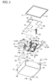
Fig. 3 is an exploded perspective view illustrating the relay unit inFig. 1B from a different angle; -
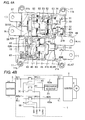
Figs. 4A and 4B are a perspective view and a circuit diagram illustrating a state in which a cover is removed from the relay unit inFig. 1B ; -
Figs. 5A and 5B are perspective views illustrating a relay unit according to a second embodiment of the present invention; -
Fig. 6 is a perspective view illustrating a state in which the cover is removed from the relay unit inFig. 5B ; -
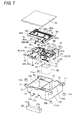
Fig. 7 is an exploded perspective view of the relay unit inFig. 5B ; -
Fig. 8 is an exploded perspective view illustrating the relay unit inFig. 5B from a different angle; -
Figs. 9A and 9B are perspective views illustrating a relay unit according to a third embodiment of the present invention; -
Fig. 10 is a perspective view illustrating a state in which the cover is removed from the relay unit inFig. 9B ; -
Fig. 11 is an exploded perspective view of the relay unit inFig. 9B ; -
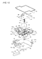
Fig. 12 is an exploded perspective view illustrating the relay unit inFig. 9B from a different angle; -
Figs. 13A and 13B are perspective views illustrating a relay unit according to a fourth embodiment of the present invention; -
Fig. 14 is an exploded perspective view of the relay unit inFig. 13B ; -
Fig. 15 is an exploded perspective view illustrating the relay unit inFig. 13B from a different angle; -
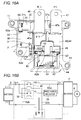
Figs. 16A and 16B are a perspective view and a circuit diagram illustrating a state in which the cover is removed from the relay unit inFig. 13B ; -
Figs. 17A and 17B are perspective views illustrating a relay unit according to a fifth embodiment of the present invention; -
Fig. 18 is an exploded perspective view of the relay unit inFig. 17B ; -
Fig. 19 is an exploded perspective view illustrating the relay unit inFig. 17B from a different angle; and -
Figs. 20A and 20B are a perspective view and a circuit diagram illustrating a state in which the cover is removed from the relay unit inFig. 17B . - A relay unit according to an exemplary embodiment of the present invention will be described with reference to
Figs. 1 to 20 . As illustrated inFigs. 1 to 4 , in arelay unit 1 according to a first embodiment, aprecharge resistor 20, aprecharge relay 30 that is of a first relay, asecond relay 40, and athird relay 50 are assembled in a housing that includes acase 10 and acover 70, and these electronic components are electrically connected to one another through a wiring board 60.As illustrated inFig. 4B , an electric connection between abattery 3 and anautomobile motor 4 through aninverter 2 can be cited as an example of an application of therelay unit 1 of the first embodiment. - For the sake of convenience, the
cover 70 is not illustrated inFig. 2 , and thewiring board 60 is not illustrated inFig. 4 while a secondary-side wiring 62a that connects thebattery 3 and themotor 4 and a primary-side wiring 62b, which is connected to coils of theprecharge relay 30 that is of the first relay, thesecond relay 40, and thethird relay 50, are illustrated inFig. 4 . - The
case 10 is formed into a box shape that has an opening in a bottom surface. In thecase 10, fixingribs 11 are laterally projected from an opening edge portion of each of side surfaces opposed to each other, and a pair ofterminal notch parts 12 and a pair ofterminal notch parts 13 are provided in opening edge portions of each of remaining side surfaces opposed to each other. A reinforcing cylindrical fitting 11b is integrally molded in a fixedhole 11a of the fixing rib 11.In thecase 10,accommodation parts precharge resistor 20 are accommodated are partitioned by apartition wall 14 that is projected from the bottom surface of thecase 10 so as to become the same height as the case 10.Therefore, thewiring board 60 can be placed and positioned on thepartition wall 14 without rattle. A height adjusting rib (not illustrated) is also provided in theaccommodation part 15a in order to adjust the positioning height of the precharge resistor 20.A connecting recessed part 16 (Fig. 3 ) that is communicated with an internal space is provided in a corner portion of a ceiling surface of thecase 10. - The
precharge resistor 20 has a solid shape that can be fitted in theaccommodation part 15a of thecase 10, andconnection terminals precharge resistor 20 is connected in series with theprecharge relay 30 through thewiring board 60, as will be described below. - The
precharge relay 30 that is of the first relay has the solid shape that can be accommodated in theaccommodation part 15b of thecase 10, and acoil terminal 31 and aconnection terminal 32 are projected from the upper surface of theprecharge relay 30. - As illustrated in
Fig. 2 , thesecond relay 40 has the solid shape that can be accommodated in theaccommodation part 15c of thecase 10, acoil 43 is wound around aspool 42 assembled in arelay body 41, and ayoke 44 having a substantial U-shape in section is assembled in the second relay 40.Thecoil 43 is connected to acoil terminal 45 through ajunction terminal 42a (Fig. 3 ) assembled in thespool 42, and thecoil terminal 45 is projected toward the opening of the case 10.L-shapedrib terminals notch parts 12 of thecase 10 are attached toterminal parts 41a (Fig. 3 ) of the relay body 41.Connectingprojection pieces rib terminals insulating rib 41b (Fig. 3 ) is projected between theterminal parts relay body 41 in order to enhance an insulating characteristic. A lower end surface of therelay body 41, the lower end surface of thespool 42, and a lower end surface of theyoke 44 are formed so as to be flush with one another, so that thesecond relay 40 can be accommodated in thecase 10 without rattle. - As illustrated in
Fig. 2 , thethird relay 50 has the solid shape that can be accommodated in theaccommodation part 15d of thecase 10, acoil 53 is wound around aspool 52 assembled in arelay body 51, and ayoke 54 having a substantial U-shape in section is assembled in the third relay 50.Thecoil 53 is connected to acoil terminal 55 through ajunction terminal 52a (Fig. 3 ) assembled in thespool 52, and thecoil terminal 55 is projected toward the opening of the case 10.L-shapedrib terminals notch parts 13 of thecase 10 are attached toterminal parts 51a (Fig. 3 ) of the relay body51.An insulating rib 51b is projected between theterminal parts relay body 51 in order to enhance the insulating characteristic. A lower end surface of therelay body 51, the lower end surface of thespool 52, and a lower end surface of theyoke 54 are formed so as to be flush with one another, so that thethird relay 50 can be accommodated in thecase 10 without rattle. - The
wiring board 60 has a planar shape that can be fitted in the opening of thecase 10, and thewiring board 60 includesterminal holes 61 while guide projectedthreads 60a are projected from the upper surface of the wiring board 60.The secondary-side wiring 62a that connects thebattery 3 and themotor 4 and the primary-side wiring 62b that connects the coils of the first, second, andthird relays projection piece 64 is vertically provided in the end portion of the secondary-side wiring 62a, and a connectingprojection piece 63 is vertically provided in the end portion of the primary-side wiring 62b.Particularly, the primary-side wiring 62b is provided along the guide projectedthread 60a, and fourpin terminals 65 are downwardly led out in parallel from the primary-side wiring 62b. - The
cover 70 has the planar shape that can seal the opening of thecase 10, and a loopedrib 71 that can be fitted in thenotch parts case 10 is formed in an outer peripheral edge portion of an inward surface. This is because a contact area with the opening edge portion of thecase 10 is enlarged to enhance a seal characteristic while a desired mechanical strength is ensured. - Accordingly, the
precharge resistor 20, theprecharge relay 30, thesecond relay 40, and thethird relay 50 are accommodated in theaccommodation parts case 10, respectively. Therefore, theconnection terminal 21a of theprecharge resistor 20 comes into surface contact with the connectingprojection piece 47a of the second relay 40.The printedwiring board 60 is assembled in thecase 10, whereby thepin terminals 65 are projected into the connecting recessedpart 16 while thecoil terminal 31 andconnection terminal 32 of theprecharge relay 30 and thecoil terminals third relays coil terminal 31, theconnection terminal 32, and thecoil terminals projection pieces 63 projected from the upper surface of thewiring board 60, and the connectingprojection piece 46a of thesecond relay 40 comes into surface contact with the connectingprojection pieces 64 of the wiring board 60.Additionally theconnection terminal 21b of theprecharge resistor 20 comes into contact with the connectingprojection pieces 64 of the wiring board 60.Then the terminal and connecting projection pieces that are in surface contact with one another are electrically connected by resistance welding or soldering. Finally thecover 70 is fitted in the opening of thecase 10 to complete assembly work. - According to the first embodiment, the
connection terminals precharge resistor 20, thecoil terminal 31 andconnection terminal 32 of theprecharge relay 30, thecoil terminals third relays projection pieces second relay 40 are projected toward the opening of thecase 10, so that connection work can easily be performed to obtain the high-productivity relay unit. Particularly, theconnection terminal 21a of theprecharge resistor 20 and the connecting projection piece of thesecond relay 40 are electrically connected in the surface contact state to form the secondary-side wiring 62a of the precharge circuit. The connectingprojection pieces wiring board 60, and the connectingprojection pieces connection terminal 21b and the like. Therefore, advantageously the connection work is more rapidly and easily performed, and therelay unit 1 having excellent impact resistance is obtained. - In the first embodiment, the second and
third relays second relay 40 andthird relay 50 are parallel with each other, and therib terminals second relay 40 and therib terminals third relay 50 are disposed so as to be projected from the external surfaces opposed to each other in the case 10.In the case where an impact force is applied from the outside, even if a large inertia force is applied to mistakenly operate one of the relays, the remaining relay surely breaks the circuit to prevent the malfunction. Therefore, advantageously the high-safety relay unit is obtained. - As illustrated in
Figs. 5 and8 , a relay unit according to a second embodiment is almost the same as the relay unit of the first embodiment, but differs from the relay unit of the first embodiment in that the externalprecharge resistor 20 is detachably attached. That is, afitting recess 17 is provided in the edge portion on one side of the upper surface of thecase 10, and retainingelastic claw parts 17a are provided. As illustrated inFig. 6 , the connectingprojection piece 47a is cut and raised from therib terminal 47 of thesecond relay 40 so as to be connected to theconnection terminal 21a of the external precharge resistor 20.A connectingprojection piece 66 extends from the secondary-side wiring 62a of thewiring board 60 so as to be connected to theconnection terminal 21b of the precharge resistor 20.Elastic spring parts Fig. 8 ) are formed in the connectingprojection pieces connection terminal - According to the second embodiment, because the external
precharge resistor 20 is detachably provided, maintenance is easy to perform. As needed basis, a user exchanges theprecharge resistor 20 to obtain a relay unit having s different specification, and thereby advantageously facilitating inventory adjustment. - As illustrated in
Figs. 9 to 12 , a relay unit according to a third embodiment is almost the same as the relay unit of the second embodiment. The relay unit of the third embodiment differs from the relay unit of the second embodiment in that therib terminals cover 70 is formed into a planar shape that can cover the lower surfaces of therib terminals frame parts rib terminals rib terminals case 10, and an insulatingwall 18a is integrally molded in the frame part 18.External threads rib terminals - According to the third embodiment, because the relay unit can be connected to the external circuit through the
external threads frame part 18 and the insulatingwall 18a are provided, advantageously a distance along the surface between therib terminals rib terminals relay unit 1 having the high insulating characteristic. - As illustrated in
Figs. 13 to 16 , a relay unit according to a fourth embodiment is almost the same as from the relay unit of the first embodiment, but differs from the relay unit of the first embodiment in that thethird relay 50 is not provided but the shapes of thecase 10 and cover 70 are changed. In the fourth embodiment, because other configurations are identical to those of the first embodiment, the same component is designated by the same numeral, and the description is omitted. - According to the fourth embodiment, because the
third relay 50 is not provided, therelay unit 1 having the small number of components and the small number of man-hours is advantageously obtained. - As illustrated in
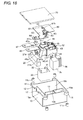
Figs. 17 to 20 , in a relay unit according to a fifth embodiment, theprecharge resistor 20, theprecharge relay 30, thesecond relay 40, and a relaycontrol circuit block 35 are accommodated inaccommodation parts case 10 is partitioned by thepartition wall 14, respectively, and these electronic components are electrically connected to one another through the wiring board 60.As illustrated inFig. 20B , the electric connection is performed such that theprecharge relay 30 that is of the first relay and thesecond relay 40 are controlled. Particularly, apin terminal 36 extending from the side surface of the relaycontrol circuit block 35 is projected so as to be able to be connected to the connecting recessedpart 16 of the case 10.Theconnection terminals 37 projected toward the opening of thecase 10 from the upper surface of the relaycontrol circuit block 35 are bonded to the connectingprojection pieces 63 vertically provided in thewiring board 60 while being in surface contact with the connectingprojection pieces 63, respectively. In the fifth embodiment, because other configurations are identical to those of the first to fourth embodiments, the same component is designated by the same numeral, and the description is omitted. - According to the fifth embodiment, because the relay
control circuit block 35 is also incorporated, the relay unit in which the work to electrically connect the external circuit is further simplified is advantageously obtained. - In the embodiments, each electronic component is connected through the wiring board by way of example. Alternatively, as needed basis, each electronic component may be connected using a lead, or each electronic component may be connected using both the printed wiring and the lead. The wiring board is not limited to the printed wiring, but the connection may be performed through a linear conductive member fixed to an insulating board.
- The present invention can be applied not only to the in-vehicle relay unit but also to a relay unit for a household power supply.
Claims (15)
- A relay unit that electrically opens and closes between a power supply (3) and a power-consuming device (4), the relay unit comprising
electronic components are disposed in a housing including a case (10) and a cover (70), the electronic components including a resistor (20), a first relay (30) connected in series with the resistor (20), and a second relay (40), the second relay (40) connecting the power supply (3)and the power-consuming device (4) through an external connection terminal (46, 47) of the second relay (40) and being connected in parallel with the resistor (20) and the first relay (30). - The relay unit according to claim 1, wherein connection terminals (21a, 21b) of the resistor (20) and connection terminals (32) of the first relay (30) are projected toward an opening of the case (10), one of the connection terminals (21a, 21b) of the resistor (20) and one of the connection terminals (32) of the first relay (30) are electrically connected to each other, the other connection terminal (21a, 21b) of the resistor (20) and one of external connection terminals (46, 47) of the second relay (40) are electrically connected to each other, and the other connection terminal (32) of the first relay (30) and the other external connection terminal (46, 47) of the second relay (40) are electrically connected to each other.
- The relay unit according to claim 1 or 2, wherein the second relay (40) is accommodated in the housing such that a winding shaft center (42) of a coil is disposed along the opening of the case (10).
- The relay unit according to any one of claims 1 to 3, wherein a connecting projection piece (47a) is projected toward the opening of the case (10), the connecting projection piece (47a) being projected from the external connection terminal (46, 47) of the second relay (40).
- The relay unit according to any one of claims 1 to 4, wherein electronic components are disposed in the housing, the electronic components including the resistor (20), the first relay (30), the second relay (40), and a third relay (50), the third relay (50) electrically connecting the power supply (3) and the power-consuming device (4) through the external connection terminal of the second relay (46, 47), preferably wherein the second relay (40) and the third relay (50) are disposed in the housing such that the winding shaft (42, 52) centers of the coils are provided along the opening of the case (10) and in parallel with each other.
- The relay unit according to claim 5, wherein the external connection terminals (46, 47, 56, 57) of the second relay (40) and the third relay (50) are laterally projected from outside surfaces opposed to each other in the case (10).
- The relay unit according to any one of claims 1 to 6, wherein each of the electronic components is accommodated in each of accommodation parts (15 a, 15b, 15c, 15d, 15e) partitioned by an insulating wall (18a) provided in the case (10).
- The relay unit according to any one of claims 1 to 7, wherein the relay unit comprises a control circuit block (35) for controlling the relays (30, 40, 50) disposed in the housing.
- The relay unit according to any one of claims 1 to 8, wherein the resistor (20) is removably disposed in a recess (17), the recess (17) being provided in an outer surface of the case (10).
- The relay unit according to any one of claims 1 to 9, wherein an insulating wall (18a) is provided between the external connection terminals (46, 47, 56, 57).
- The relay unit according to any one of claims 1 to 10, wherein one of the connection terminals (21a, 21b) of the resistor (20) and one of the connection terminals (32) of the first relay (30) are connected to each other through a connecting projection piece (63, 64) vertically provided in a wiring board (60) while insulated from a relay driving coil terminal (31, 45, 55) of the relay, and the other connection terminal (32) of the first relay (30) and one of the external connection terminals (46, 47) of the second relay (40) are connected to each other through the connecting projection piece (63, 64) vertically provided in the wiring board (60) while insulated from the relay driving coil terminal of the relay, and the other connection terminal (21a, 21b) of the resistor (20) and the other external connection terminal (46, 47) of the second relay (40) are directly electrically connected to each other.
- The relay unit according to claim 11, wherein the coil terminal (21a, 21b) is projected toward the opening of the case (10), and the coil terminal (21a, 21b) is electrically connected through the wiring board (60).
- The relay unit according to claim 12, wherein a guide projected thread (60a) is projected on the wiring board (60) in order to guide a wiring electrically connecting the coil terminal (21a, 21b).
- The relay unit according to any one of claims 11 to 13, wherein the connecting projection piece (63, 64) is vertically provided on the wiring board (60).
- A method for producing the relay unit according to any one of claims 11 to 14 in which, after each electronic component of the relay unit is accommodated from an opening of a case (10), a coil terminal (21a, 21b) projected toward the opening of the case (10) from the electronic component is electrically connected through a wiring board (60).
Applications Claiming Priority (1)
| Application Number | Priority Date | Filing Date | Title |
|---|---|---|---|
| JP2012111596A JP6024194B2 (en) | 2012-05-15 | 2012-05-15 | Relay unit and manufacturing method thereof |
Publications (2)
| Publication Number | Publication Date |
|---|---|
| EP2665080A1 true EP2665080A1 (en) | 2013-11-20 |
| EP2665080B1 EP2665080B1 (en) | 2014-12-31 |
Family
ID=48190806
Family Applications (1)
| Application Number | Title | Priority Date | Filing Date |
|---|---|---|---|
| EP13165838.7A Active EP2665080B1 (en) | 2012-05-15 | 2013-04-29 | Relay unit and producing method thereof |
Country Status (5)
| Country | Link |
|---|---|
| US (1) | US9502906B2 (en) |
| EP (1) | EP2665080B1 (en) |
| JP (1) | JP6024194B2 (en) |
| KR (1) | KR101435317B1 (en) |
| CN (1) | CN103426686B (en) |
Families Citing this family (18)
| Publication number | Priority date | Publication date | Assignee | Title |
|---|---|---|---|---|
| JP6287128B2 (en) * | 2013-11-29 | 2018-03-07 | オムロン株式会社 | Backflow prevention device |
| DE102014107742B4 (en) * | 2014-06-03 | 2019-01-31 | Lisa Dräxlmaier GmbH | Precharge module and precharge circuit |
| KR102531475B1 (en) | 2016-02-02 | 2023-05-11 | 엘에스일렉트릭(주) | Relay |
| JP6889643B2 (en) * | 2017-09-15 | 2021-06-18 | 矢崎総業株式会社 | Unit with built-in electronic components |
| CN108964167B (en) * | 2017-09-30 | 2024-05-14 | 厦门宏发电力电器有限公司 | Pre-charging module |
| JP7052689B2 (en) * | 2018-11-21 | 2022-04-12 | 株式会社オートネットワーク技術研究所 | Circuit configuration |
| CN109638920B (en) * | 2018-12-28 | 2024-07-12 | 上海飞龙新能源汽车部件有限公司 | A high voltage pre-charge module circuit for load energy storage capacitor |
| JP7182079B2 (en) * | 2019-04-25 | 2022-12-02 | 株式会社オートネットワーク技術研究所 | circuit construct |
| CN110890250A (en) * | 2019-09-30 | 2020-03-17 | 厦门宏发汽车电子有限公司 | Miniaturized combined relay capable of controlling two paths of loads |
| JP7529440B2 (en) * | 2020-05-25 | 2024-08-06 | 矢崎総業株式会社 | Electrical Junction Box |
| KR102872922B1 (en) * | 2020-10-27 | 2025-10-16 | 주식회사 엘지에너지솔루션 | Relay switch device with integrated precharge system |
| EP4237275A4 (en) * | 2020-10-30 | 2024-10-16 | Yazaki North America, Inc. | Arc suppression pre-charge circuit |
| JP7480714B2 (en) * | 2021-01-18 | 2024-05-10 | 株式会社デンソー | Power Distribution Equipment |
| JP7639525B2 (en) * | 2021-04-21 | 2025-03-05 | 株式会社オートネットワーク技術研究所 | Power Control Device |
| CN115939946B (en) * | 2022-12-19 | 2026-01-02 | 武汉嘉晨电子技术股份有限公司 | A versatile high-voltage distribution box |
| WO2025062491A1 (en) * | 2023-09-19 | 2025-03-27 | 本田技研工業株式会社 | Electric vehicle |
| CN121238338A (en) * | 2024-06-27 | 2025-12-30 | 宁德时代新能源科技股份有限公司 | Distribution boxes, batteries and electrical equipment |
| CN118692874B (en) * | 2024-08-23 | 2024-11-26 | 宁波峰梅新能源汽车科技股份有限公司 | High-voltage pre-charging circuit breaker with pre-charging and circuit breaking functions and manufacturing method thereof |
Citations (6)
| Publication number | Priority date | Publication date | Assignee | Title |
|---|---|---|---|---|
| EP1128408A2 (en) * | 2000-02-22 | 2001-08-29 | Omron Corporation | Relay unit for power supply circuit, and housing used in the same |
| JP2001359283A (en) * | 2000-06-12 | 2001-12-26 | Matsushita Electric Works Ltd | Relay unit |
| US20050253460A1 (en) * | 2004-05-12 | 2005-11-17 | Panasonic Ev Energy Co., Ltd. | Electric vehicle |
| US20070108939A1 (en) * | 2005-11-15 | 2007-05-17 | Panasonic Ev Energy Co., Ltd. | Battery pack |
| JP2008270121A (en) * | 2007-04-25 | 2008-11-06 | Sanyo Electric Co Ltd | Power supply device for vehicle |
| JP2009193721A (en) * | 2008-02-12 | 2009-08-27 | Honda Motor Co Ltd | Contactor box connection structure |
Family Cites Families (2)
| Publication number | Priority date | Publication date | Assignee | Title |
|---|---|---|---|---|
| US6062916A (en) * | 1998-07-14 | 2000-05-16 | General Motors Corporation | Printed circuit board with pass through bussed terminal system for a bussed electrical distribution center |
| JP5471532B2 (en) | 2010-02-04 | 2014-04-16 | 株式会社デンソー | Switch device for starter |
-
2012
- 2012-05-15 JP JP2012111596A patent/JP6024194B2/en active Active
-
2013
- 2013-02-19 KR KR1020130017385A patent/KR101435317B1/en active Active
- 2013-04-24 US US13/869,908 patent/US9502906B2/en active Active
- 2013-04-26 CN CN201310149150.4A patent/CN103426686B/en active Active
- 2013-04-29 EP EP13165838.7A patent/EP2665080B1/en active Active
Patent Citations (7)
| Publication number | Priority date | Publication date | Assignee | Title |
|---|---|---|---|---|
| EP1128408A2 (en) * | 2000-02-22 | 2001-08-29 | Omron Corporation | Relay unit for power supply circuit, and housing used in the same |
| JP2001237558A (en) | 2000-02-22 | 2001-08-31 | Omron Corp | Power supply circuit cutoff relay unit and its relay unit case |
| JP2001359283A (en) * | 2000-06-12 | 2001-12-26 | Matsushita Electric Works Ltd | Relay unit |
| US20050253460A1 (en) * | 2004-05-12 | 2005-11-17 | Panasonic Ev Energy Co., Ltd. | Electric vehicle |
| US20070108939A1 (en) * | 2005-11-15 | 2007-05-17 | Panasonic Ev Energy Co., Ltd. | Battery pack |
| JP2008270121A (en) * | 2007-04-25 | 2008-11-06 | Sanyo Electric Co Ltd | Power supply device for vehicle |
| JP2009193721A (en) * | 2008-02-12 | 2009-08-27 | Honda Motor Co Ltd | Contactor box connection structure |
Also Published As
| Publication number | Publication date |
|---|---|
| US20130313915A1 (en) | 2013-11-28 |
| JP6024194B2 (en) | 2016-11-09 |
| CN103426686B (en) | 2015-09-09 |
| US9502906B2 (en) | 2016-11-22 |
| JP2013239581A (en) | 2013-11-28 |
| KR101435317B1 (en) | 2014-08-27 |
| CN103426686A (en) | 2013-12-04 |
| EP2665080B1 (en) | 2014-12-31 |
| KR20130127911A (en) | 2013-11-25 |
Similar Documents
| Publication | Publication Date | Title |
|---|---|---|
| EP2665080B1 (en) | Relay unit and producing method thereof | |
| US8305166B2 (en) | Electromagnetic relay | |
| JP6332480B1 (en) | Magnetic contactor | |
| EP3439012A1 (en) | Contact device and electromagnetic contactor using same | |
| JP5824080B2 (en) | Electronic car transformer module | |
| JP5714716B2 (en) | Power control device | |
| EP2876986B1 (en) | Housing, bobbin, and electronic device | |
| JP2016171028A (en) | Battery module | |
| CN110071018A (en) | DC relay including auxiliary contact | |
| EP3041013A1 (en) | Rfid tag based state monitoring of contactors | |
| JP2018125952A (en) | Power supply control device | |
| JP2020131999A (en) | Electronic module | |
| JP2014195339A (en) | Power supply controller | |
| JP2009183030A (en) | Electrical junction box | |
| EP4276876A1 (en) | Electromagnetic relay | |
| CN219842936U (en) | Reed structure and relay | |
| JP2021082402A (en) | Electromagnetic relay module and electric connection device | |
| JP2009289498A (en) | Remote control relay | |
| JP2010049815A (en) | On-vehicle electric component control unit and control component | |
| KR102398110B1 (en) | In-cable controller of charger | |
| KR102177144B1 (en) | Trigger switch | |
| JP2017195097A (en) | Electromagnetic relay | |
| JP6145343B2 (en) | Electrical junction box | |
| KR102765639B1 (en) | Battery Disconnect Apparatus | |
| JP2012170179A (en) | Electrical junction box |
Legal Events
| Date | Code | Title | Description |
|---|---|---|---|
| PUAI | Public reference made under article 153(3) epc to a published international application that has entered the european phase |
Free format text: ORIGINAL CODE: 0009012 |
|
| AK | Designated contracting states |
Kind code of ref document: A1 Designated state(s): AL AT BE BG CH CY CZ DE DK EE ES FI FR GB GR HR HU IE IS IT LI LT LU LV MC MK MT NL NO PL PT RO RS SE SI SK SM TR |
|
| AX | Request for extension of the european patent |
Extension state: BA ME |
|
| 17P | Request for examination filed |
Effective date: 20140520 |
|
| RBV | Designated contracting states (corrected) |
Designated state(s): AL AT BE BG CH CY CZ DE DK EE ES FI FR GB GR HR HU IE IS IT LI LT LU LV MC MK MT NL NO PL PT RO RS SE SI SK SM TR |
|
| GRAP | Despatch of communication of intention to grant a patent |
Free format text: ORIGINAL CODE: EPIDOSNIGR1 |
|
| INTG | Intention to grant announced |
Effective date: 20140717 |
|
| RIN1 | Information on inventor provided before grant (corrected) |
Inventor name: HASHIMOTO, RYUICHI Inventor name: YANO, KEISUKE |
|
| GRAS | Grant fee paid |
Free format text: ORIGINAL CODE: EPIDOSNIGR3 |
|
| GRAA | (expected) grant |
Free format text: ORIGINAL CODE: 0009210 |
|
| AK | Designated contracting states |
Kind code of ref document: B1 Designated state(s): AL AT BE BG CH CY CZ DE DK EE ES FI FR GB GR HR HU IE IS IT LI LT LU LV MC MK MT NL NO PL PT RO RS SE SI SK SM TR |
|
| REG | Reference to a national code |
Ref country code: CH Ref legal event code: EP Ref country code: GB Ref legal event code: FG4D |
|
| REG | Reference to a national code |
Ref country code: IE Ref legal event code: FG4D |
|
| REG | Reference to a national code |
Ref country code: AT Ref legal event code: REF Ref document number: 704832 Country of ref document: AT Kind code of ref document: T Effective date: 20150215 |
|
| REG | Reference to a national code |
Ref country code: DE Ref legal event code: R096 Ref document number: 602013000731 Country of ref document: DE Effective date: 20150219 |
|
| REG | Reference to a national code |
Ref country code: FR Ref legal event code: PLFP Year of fee payment: 3 |
|
| REG | Reference to a national code |
Ref country code: DE Ref legal event code: R082 Ref document number: 602013000731 Country of ref document: DE Representative=s name: HORN KLEIMANN WAITZHOFER PATENTANWAELTE PARTG , DE |
|
| PG25 | Lapsed in a contracting state [announced via postgrant information from national office to epo] |
Ref country code: NO Free format text: LAPSE BECAUSE OF FAILURE TO SUBMIT A TRANSLATION OF THE DESCRIPTION OR TO PAY THE FEE WITHIN THE PRESCRIBED TIME-LIMIT Effective date: 20150331 Ref country code: LT Free format text: LAPSE BECAUSE OF FAILURE TO SUBMIT A TRANSLATION OF THE DESCRIPTION OR TO PAY THE FEE WITHIN THE PRESCRIBED TIME-LIMIT Effective date: 20141231 Ref country code: FI Free format text: LAPSE BECAUSE OF FAILURE TO SUBMIT A TRANSLATION OF THE DESCRIPTION OR TO PAY THE FEE WITHIN THE PRESCRIBED TIME-LIMIT Effective date: 20141231 |
|
| REG | Reference to a national code |
Ref country code: NL Ref legal event code: VDEP Effective date: 20141231 |
|
| REG | Reference to a national code |
Ref country code: LT Ref legal event code: MG4D |
|
| PG25 | Lapsed in a contracting state [announced via postgrant information from national office to epo] |
Ref country code: GR Free format text: LAPSE BECAUSE OF FAILURE TO SUBMIT A TRANSLATION OF THE DESCRIPTION OR TO PAY THE FEE WITHIN THE PRESCRIBED TIME-LIMIT Effective date: 20150401 Ref country code: RS Free format text: LAPSE BECAUSE OF FAILURE TO SUBMIT A TRANSLATION OF THE DESCRIPTION OR TO PAY THE FEE WITHIN THE PRESCRIBED TIME-LIMIT Effective date: 20141231 Ref country code: HR Free format text: LAPSE BECAUSE OF FAILURE TO SUBMIT A TRANSLATION OF THE DESCRIPTION OR TO PAY THE FEE WITHIN THE PRESCRIBED TIME-LIMIT Effective date: 20141231 Ref country code: SE Free format text: LAPSE BECAUSE OF FAILURE TO SUBMIT A TRANSLATION OF THE DESCRIPTION OR TO PAY THE FEE WITHIN THE PRESCRIBED TIME-LIMIT Effective date: 20141231 Ref country code: LV Free format text: LAPSE BECAUSE OF FAILURE TO SUBMIT A TRANSLATION OF THE DESCRIPTION OR TO PAY THE FEE WITHIN THE PRESCRIBED TIME-LIMIT Effective date: 20141231 |
|
| REG | Reference to a national code |
Ref country code: AT Ref legal event code: MK05 Ref document number: 704832 Country of ref document: AT Kind code of ref document: T Effective date: 20141231 |
|
| PG25 | Lapsed in a contracting state [announced via postgrant information from national office to epo] |
Ref country code: NL Free format text: LAPSE BECAUSE OF FAILURE TO SUBMIT A TRANSLATION OF THE DESCRIPTION OR TO PAY THE FEE WITHIN THE PRESCRIBED TIME-LIMIT Effective date: 20141231 |
|
| PG25 | Lapsed in a contracting state [announced via postgrant information from national office to epo] |
Ref country code: ES Free format text: LAPSE BECAUSE OF FAILURE TO SUBMIT A TRANSLATION OF THE DESCRIPTION OR TO PAY THE FEE WITHIN THE PRESCRIBED TIME-LIMIT Effective date: 20141231 Ref country code: SK Free format text: LAPSE BECAUSE OF FAILURE TO SUBMIT A TRANSLATION OF THE DESCRIPTION OR TO PAY THE FEE WITHIN THE PRESCRIBED TIME-LIMIT Effective date: 20141231 Ref country code: CZ Free format text: LAPSE BECAUSE OF FAILURE TO SUBMIT A TRANSLATION OF THE DESCRIPTION OR TO PAY THE FEE WITHIN THE PRESCRIBED TIME-LIMIT Effective date: 20141231 Ref country code: RO Free format text: LAPSE BECAUSE OF FAILURE TO SUBMIT A TRANSLATION OF THE DESCRIPTION OR TO PAY THE FEE WITHIN THE PRESCRIBED TIME-LIMIT Effective date: 20141231 |
|
| PG25 | Lapsed in a contracting state [announced via postgrant information from national office to epo] |
Ref country code: PL Free format text: LAPSE BECAUSE OF FAILURE TO SUBMIT A TRANSLATION OF THE DESCRIPTION OR TO PAY THE FEE WITHIN THE PRESCRIBED TIME-LIMIT Effective date: 20141231 Ref country code: IS Free format text: LAPSE BECAUSE OF FAILURE TO SUBMIT A TRANSLATION OF THE DESCRIPTION OR TO PAY THE FEE WITHIN THE PRESCRIBED TIME-LIMIT Effective date: 20150430 Ref country code: AT Free format text: LAPSE BECAUSE OF FAILURE TO SUBMIT A TRANSLATION OF THE DESCRIPTION OR TO PAY THE FEE WITHIN THE PRESCRIBED TIME-LIMIT Effective date: 20141231 |
|
| REG | Reference to a national code |
Ref country code: DE Ref legal event code: R097 Ref document number: 602013000731 Country of ref document: DE |
|
| PG25 | Lapsed in a contracting state [announced via postgrant information from national office to epo] |
Ref country code: DK Free format text: LAPSE BECAUSE OF FAILURE TO SUBMIT A TRANSLATION OF THE DESCRIPTION OR TO PAY THE FEE WITHIN THE PRESCRIBED TIME-LIMIT Effective date: 20141231 Ref country code: EE Free format text: LAPSE BECAUSE OF FAILURE TO SUBMIT A TRANSLATION OF THE DESCRIPTION OR TO PAY THE FEE WITHIN THE PRESCRIBED TIME-LIMIT Effective date: 20141231 |
|
| PLBE | No opposition filed within time limit |
Free format text: ORIGINAL CODE: 0009261 |
|
| STAA | Information on the status of an ep patent application or granted ep patent |
Free format text: STATUS: NO OPPOSITION FILED WITHIN TIME LIMIT |
|
| PG25 | Lapsed in a contracting state [announced via postgrant information from national office to epo] |
Ref country code: LU Free format text: LAPSE BECAUSE OF FAILURE TO SUBMIT A TRANSLATION OF THE DESCRIPTION OR TO PAY THE FEE WITHIN THE PRESCRIBED TIME-LIMIT Effective date: 20150429 Ref country code: MC Free format text: LAPSE BECAUSE OF FAILURE TO SUBMIT A TRANSLATION OF THE DESCRIPTION OR TO PAY THE FEE WITHIN THE PRESCRIBED TIME-LIMIT Effective date: 20141231 |
|
| 26N | No opposition filed |
Effective date: 20151001 |
|
| REG | Reference to a national code |
Ref country code: IE Ref legal event code: MM4A |
|
| PG25 | Lapsed in a contracting state [announced via postgrant information from national office to epo] |
Ref country code: SI Free format text: LAPSE BECAUSE OF FAILURE TO SUBMIT A TRANSLATION OF THE DESCRIPTION OR TO PAY THE FEE WITHIN THE PRESCRIBED TIME-LIMIT Effective date: 20141231 |
|
| REG | Reference to a national code |
Ref country code: FR Ref legal event code: PLFP Year of fee payment: 4 |
|
| PG25 | Lapsed in a contracting state [announced via postgrant information from national office to epo] |
Ref country code: IE Free format text: LAPSE BECAUSE OF NON-PAYMENT OF DUE FEES Effective date: 20150429 |
|
| PG25 | Lapsed in a contracting state [announced via postgrant information from national office to epo] |
Ref country code: BE Free format text: LAPSE BECAUSE OF FAILURE TO SUBMIT A TRANSLATION OF THE DESCRIPTION OR TO PAY THE FEE WITHIN THE PRESCRIBED TIME-LIMIT Effective date: 20141231 |
|
| REG | Reference to a national code |
Ref country code: CH Ref legal event code: PL |
|
| PG25 | Lapsed in a contracting state [announced via postgrant information from national office to epo] |
Ref country code: MT Free format text: LAPSE BECAUSE OF FAILURE TO SUBMIT A TRANSLATION OF THE DESCRIPTION OR TO PAY THE FEE WITHIN THE PRESCRIBED TIME-LIMIT Effective date: 20141231 |
|
| PG25 | Lapsed in a contracting state [announced via postgrant information from national office to epo] |
Ref country code: LI Free format text: LAPSE BECAUSE OF NON-PAYMENT OF DUE FEES Effective date: 20160430 Ref country code: CH Free format text: LAPSE BECAUSE OF NON-PAYMENT OF DUE FEES Effective date: 20160430 |
|
| REG | Reference to a national code |
Ref country code: FR Ref legal event code: PLFP Year of fee payment: 5 |
|
| PG25 | Lapsed in a contracting state [announced via postgrant information from national office to epo] |
Ref country code: BG Free format text: LAPSE BECAUSE OF FAILURE TO SUBMIT A TRANSLATION OF THE DESCRIPTION OR TO PAY THE FEE WITHIN THE PRESCRIBED TIME-LIMIT Effective date: 20141231 Ref country code: HU Free format text: LAPSE BECAUSE OF FAILURE TO SUBMIT A TRANSLATION OF THE DESCRIPTION OR TO PAY THE FEE WITHIN THE PRESCRIBED TIME-LIMIT; INVALID AB INITIO Effective date: 20130429 |
|
| PG25 | Lapsed in a contracting state [announced via postgrant information from national office to epo] |
Ref country code: CY Free format text: LAPSE BECAUSE OF FAILURE TO SUBMIT A TRANSLATION OF THE DESCRIPTION OR TO PAY THE FEE WITHIN THE PRESCRIBED TIME-LIMIT Effective date: 20141231 |
|
| PG25 | Lapsed in a contracting state [announced via postgrant information from national office to epo] |
Ref country code: TR Free format text: LAPSE BECAUSE OF FAILURE TO SUBMIT A TRANSLATION OF THE DESCRIPTION OR TO PAY THE FEE WITHIN THE PRESCRIBED TIME-LIMIT Effective date: 20141231 |
|
| REG | Reference to a national code |
Ref country code: FR Ref legal event code: PLFP Year of fee payment: 6 |
|
| PG25 | Lapsed in a contracting state [announced via postgrant information from national office to epo] |
Ref country code: SM Free format text: LAPSE BECAUSE OF FAILURE TO SUBMIT A TRANSLATION OF THE DESCRIPTION OR TO PAY THE FEE WITHIN THE PRESCRIBED TIME-LIMIT Effective date: 20141231 |
|
| PG25 | Lapsed in a contracting state [announced via postgrant information from national office to epo] |
Ref country code: MK Free format text: LAPSE BECAUSE OF FAILURE TO SUBMIT A TRANSLATION OF THE DESCRIPTION OR TO PAY THE FEE WITHIN THE PRESCRIBED TIME-LIMIT Effective date: 20141231 |
|
| PG25 | Lapsed in a contracting state [announced via postgrant information from national office to epo] |
Ref country code: PT Free format text: LAPSE BECAUSE OF FAILURE TO SUBMIT A TRANSLATION OF THE DESCRIPTION OR TO PAY THE FEE WITHIN THE PRESCRIBED TIME-LIMIT Effective date: 20141231 |
|
| PG25 | Lapsed in a contracting state [announced via postgrant information from national office to epo] |
Ref country code: AL Free format text: LAPSE BECAUSE OF FAILURE TO SUBMIT A TRANSLATION OF THE DESCRIPTION OR TO PAY THE FEE WITHIN THE PRESCRIBED TIME-LIMIT Effective date: 20141231 |
|
| PGFP | Annual fee paid to national office [announced via postgrant information from national office to epo] |
Ref country code: FR Payment date: 20230309 Year of fee payment: 11 |
|
| PGFP | Annual fee paid to national office [announced via postgrant information from national office to epo] |
Ref country code: GB Payment date: 20230309 Year of fee payment: 11 |
|
| GBPC | Gb: european patent ceased through non-payment of renewal fee |
Effective date: 20240429 |
|
| PG25 | Lapsed in a contracting state [announced via postgrant information from national office to epo] |
Ref country code: GB Free format text: LAPSE BECAUSE OF NON-PAYMENT OF DUE FEES Effective date: 20240429 |
|
| PG25 | Lapsed in a contracting state [announced via postgrant information from national office to epo] |
Ref country code: FR Free format text: LAPSE BECAUSE OF NON-PAYMENT OF DUE FEES Effective date: 20240430 |
|
| PG25 | Lapsed in a contracting state [announced via postgrant information from national office to epo] |
Ref country code: GB Free format text: LAPSE BECAUSE OF NON-PAYMENT OF DUE FEES Effective date: 20240429 Ref country code: FR Free format text: LAPSE BECAUSE OF NON-PAYMENT OF DUE FEES Effective date: 20240430 |
|
| PGFP | Annual fee paid to national office [announced via postgrant information from national office to epo] |
Ref country code: DE Payment date: 20250417 Year of fee payment: 13 |
|
| PGFP | Annual fee paid to national office [announced via postgrant information from national office to epo] |
Ref country code: IT Payment date: 20250430 Year of fee payment: 13 |