EP2665036A1 - Detection device and detection method - Google Patents
Detection device and detection method Download PDFInfo
- Publication number
- EP2665036A1 EP2665036A1 EP11855890.7A EP11855890A EP2665036A1 EP 2665036 A1 EP2665036 A1 EP 2665036A1 EP 11855890 A EP11855890 A EP 11855890A EP 2665036 A1 EP2665036 A1 EP 2665036A1
- Authority
- EP
- European Patent Office
- Prior art keywords
- image
- cross region
- unit
- feature value
- section
- Prior art date
- Legal status (The legal status is an assumption and is not a legal conclusion. Google has not performed a legal analysis and makes no representation as to the accuracy of the status listed.)
- Withdrawn
Links
Images




Classifications
-
- G—PHYSICS
- G06—COMPUTING OR CALCULATING; COUNTING
- G06V—IMAGE OR VIDEO RECOGNITION OR UNDERSTANDING
- G06V40/00—Recognition of biometric, human-related or animal-related patterns in image or video data
- G06V40/10—Human or animal bodies, e.g. vehicle occupants or pedestrians; Body parts, e.g. hands
- G06V40/18—Eye characteristics, e.g. of the iris
- G06V40/19—Sensors therefor
-
- G—PHYSICS
- G06—COMPUTING OR CALCULATING; COUNTING
- G06V—IMAGE OR VIDEO RECOGNITION OR UNDERSTANDING
- G06V10/00—Arrangements for image or video recognition or understanding
- G06V10/40—Extraction of image or video features
- G06V10/44—Local feature extraction by analysis of parts of the pattern, e.g. by detecting edges, contours, loops, corners, strokes or intersections; Connectivity analysis, e.g. of connected components
- G06V10/443—Local feature extraction by analysis of parts of the pattern, e.g. by detecting edges, contours, loops, corners, strokes or intersections; Connectivity analysis, e.g. of connected components by matching or filtering
- G06V10/446—Local feature extraction by analysis of parts of the pattern, e.g. by detecting edges, contours, loops, corners, strokes or intersections; Connectivity analysis, e.g. of connected components by matching or filtering using Haar-like filters, e.g. using integral image techniques
-
- G—PHYSICS
- G06—COMPUTING OR CALCULATING; COUNTING
- G06V—IMAGE OR VIDEO RECOGNITION OR UNDERSTANDING
- G06V40/00—Recognition of biometric, human-related or animal-related patterns in image or video data
- G06V40/10—Human or animal bodies, e.g. vehicle occupants or pedestrians; Body parts, e.g. hands
- G06V40/16—Human faces, e.g. facial parts, sketches or expressions
- G06V40/161—Detection; Localisation; Normalisation
- G06V40/166—Detection; Localisation; Normalisation using acquisition arrangements
Definitions
- the present invention relates to a detection apparatus and a detection method, and more particularly, to a detection apparatus and a detection method for detecting an object to be detected by use of stereo images captured by two imaging systems at the same timing.
- the red-eye effect may occur due to low illuminance.
- pupils are detected by using a fact that the brightness of a portion corresponding to a pupil is normally lower than the brightness of a region around the portion in an image.
- the red-eye effect occurs, the brightness of an image region corresponding to a pupil increases.
- pupils cannot be stably detected by the pupil detection method targeted at normal pupils.
- pupils are detected by using a plurality of images captured at different timings while positively causing the red-eye effect to occur over the entire pupil.
- the red-eye effect does not occur over the entire pupil, but occurs only in a portion of the pupil in some cases.
- only "a partial region of the pupil" where the red-eye effect occurs can be detected in the aforementioned conventional technique.
- the position of "a partial region of the pupil” where the red-eye effect occurs largely depends on the line of sight, the positional relationship between an imaging apparatus and a face, or the like. Thus, even if "a partial region of the pupil" where the red-eye effect occurs can be detected, the center position of the pupil is difficult to identify from the detection result.
- a detection apparatus reflecting one aspect of the present invention is a detection apparatus for detecting an object to be detected in a first image and a second image captured by two imaging systems at a same timing, including: an integral image calculation section that calculates a first integral image and a second integral image from the first image and the second image; an acquisition section that acquires a unit image pair composed of a first unit image and a second unit image from the first integral image and the second integral image, wherein a plurality of unit image pairs cut out at different positions from each other are acquired by sequentially shifting the cutout positions of the unit images; a setting section that sets, with respect to each of the unit image pairs, M cross region patterns (M is a natural number not less than 2), each of the M cross region patterns being defined by positions and sizes of N setting regions (N is a natural number not less than 2) within the respective unit images, and setting image information indicating whether the respective setting regions are set within the first unit image or the second unit image; a feature value calculation section that calculates a feature value in each of the image regions where the
- a detection method reflecting one aspect of the present invention is a detection method for detecting an object to be detected in a first image and a second image captured by two imagine systems at a same timing, including: an integral image calculation step of calculating a first integral image and a second integral image from the first image and the second image; an acquisition step of acquiring a unit image pair composed of a first unit image and a second unit image from the first integral image and the second integral image, wherein a plurality of unit image pairs cut out at different positions from each other are acquired by sequentially shifting the cutout positions of the unit images; a setting step of setting, with respect to each of the unit image pairs, M cross region patterns (M is a natural number not less than 2), each of the M cross region patterns being defined by positions and sizes of N setting regions (N is a natural number not less than 2) within the respective unit images, and setting image information indicating whether the respective setting regions are set within the first unit image or the second unit image; a feature value calculation step of calculating a feature value in each of the image regions where the
- the present invention can provide a detection apparatus and a detection method which can stably detect an object to be detected even when the object to be detected is captured in images differently and in various ways depending on the relative positional relationship between the object to be detected and an imaging apparatus.
- Fig. 1 shows the main configuration of detection apparatus 100 according to one embodiment of the present invention.
- detection apparatus 100 includes integral image calculation section 104, unit image acquisition section 105, cross region pattern setting section 106, feature value calculation section 107, and detection section 108.
- Integral image calculation section 104 calculates a "first integral image” and a "second integral image” from a first image and a second image as stereo images captured by two imaging systems at the same timing.
- the "integral image” is a data structure for effectively calculating the sum of pixel values in a given rectangular region.
- the integral image calculated from the first image captured by a first imaging system is the "first integral image”
- the integral image calculated from the second image captured by a second imaging system is the "second integral image”.
- Unit image acquisition section 105 acquires unit images having a predetermined size from the first integral image and the second integral image.
- first unit image the unit image acquired from the first integral image
- second unit image the unit image acquired from the second integral image
- unit image acquisition section 105 acquires a "unit image pair" composed of the first unit image and the second unit image respectively from the first integral image and the second integral image.
- the first unit image and the second unit image respectively correspond to partial images of the first image and the second image in which the same photographic object is captured. That is, there is parallax between the first imaging system and the second imaging system.
- the coordinates of the first unit image and the coordinates of the second unit image are separated from each other by a distance corresponding to the parallax.
- Unit image acquisition section 105 acquires the unit images respectively from the first integral image and the second integral image by sequentially shifting cutout positions of the unit images. Unit image acquisition section 105 can thereby acquire a plurality of unit image pairs cut out at different positions from each other.
- Cross region pattern setting section 106 sequentially sets a plurality of "cross region patterns" with respect to each of the unit image pairs.
- Each of the cross region patterns is defined by the positions (i.e., the coordinates on a unit image plane) and the sizes of N regions (N is a natural number not less than 2) within the respective unit images, and setting image information indicating whether the respective regions are set within the first unit image or the second unit image.
- the unit image plane coordinates of a region constituting one cross region pattern differ from the unit image plane coordinates of a region constituting another cross region pattern.
- Feature value calculation section 107 calculates a feature value in each of the image regions where the cross region patterns are set by cross region pattern setting section 106, and calculates a total feature value for each of the cross region patterns from the calculated feature values.
- Detection section 108 detects an object to be detected based on the total feature value for each of the plurality of cross region patterns, and a strong classifier composed of a plurality of weak classifiers each corresponding to each of the plurality of cross region patterns.
- Fig. 2 shows the configuration of detection apparatus 100 according to one embodiment of the present invention.
- detection apparatus 100 includes first imaging section 101, second imaging section 102, synchronization section 103, integral image calculation section 104, unit image acquisition section 105, cross region pattern setting section 106, feature value calculation section 107, detection section 108, cross region pattern setting section 109, feature value calculation section 110, feature learning section 111, and classifier storage section 112.
- First imaging section 101 receives a synchronous signal output from synchronization section 103, and captures a human face at a timing according to the synchronous signal.
- An image captured by first imaging section 101 (simply referred to as "first image") is output to integral image calculation section 104.
- First imaging section 101 is installed at a place, such as on a television, on an automobile steering wheel, and on a dashboard, where the imaging section easily captures a face.
- First imaging section 101 also includes an image sensor such as CCD (Charge Coupled Devices) and CMOS (Complementary Metal Oxide Semiconductor).
- CCD Charge Coupled Devices
- CMOS Complementary Metal Oxide Semiconductor
- Second imaging section 102 has the same configuration as that of first imaging section 101. That is, second imaging section 102 receives a synchronous signal output from synchronization section 103, and captures the human face at a timing according to the synchronous signal. First imaging section 101 and second imaging section 102 can thereby capture the human face at the same timing.
- Second imaging section 102 is installed at a position apart a predetermined distance from first imaging section 101 and where the imaging section can capture the same photographic object as that of first imaging section 101.
- An image captured by second imaging section 102 (simply referred to as "second image") is output to integral image calculation section 104. That is, the first image and the second image are images of the same photographic object captured at the same timing from different directions.
- the captured first and second images will be described by setting the image horizontal direction as X axis, the image vertical direction as Y axis, and one pixel as one coordinate point.
- Synchronization section 103 outputs the synchronous signals to first imaging section 101 and second imaging section 102. Synchronization section 103 outputs the synchronous signals for a time length equivalent to that from an exposure start to an exposure end, for example. First imaging section 101 and second imaging section 102 can thereby capture an object at the same timing.
- a trigger signal for the output of the synchronous signals may be manually given to synchronization section 103 by a user, or may be automatically given to synchronization section 103.
- First imaging section 101, second imaging section 102, and synchronization section 103 described above are mounted as, for example, a stereo camera, and capture the face at the synchronized timing from different viewpoints. That is, the positional relationship between first imaging section 101 and second imaging section 102 is fixed and does not change in each image capturing operation as described above.
- Integral image calculation section 104 calculates an integral image from each of the first image and the second image input thereto.
- the integral image calculated from the first image is a first integral image
- the integral image calculated from the second image is a second integral image.
- Unit image acquisition section 105 acquires a "unit image pair" composed of a first unit image and a second unit image from the first integral image and the second integral image.
- Unit image acquisition section 105 acquires, from each of the first integral image and the second integral image, a plurality of unit image pairs cut out at different positions from each other, by sequentially shifting the cutout positions of the unit images.
- Cross region pattern setting section 106 sequentially sets a plurality of "cross region patterns" with respect to each of the unit image pairs.
- cross region pattern setting section 106 holds a first cross region pattern group.
- the first cross region pattern group is composed of the M cross region patterns (M is a natural number not less than 2).
- Cross region pattern setting section 106 sequentially sets the constituent patterns with respect to each of the unit image pairs so as to set all the constituent patterns of the first cross region pattern group.
- Feature value calculation section 107 calculates a feature value in each of the image regions where the cross region patterns are set by cross region pattern setting section 106, and calculates a total feature value for each of the cross region patterns from the calculated feature values.
- Detection section 108 detects an object to be detected based on the total feature value for each of the constituent patterns of the first cross region pattern group, and a strong classifier composed of a plurality of weak classifiers stored in classifier storage section 112.
- Each of the plurality of weak classifiers constituting the strong classifier corresponds to each of the plurality of cross region patterns constituting the first cross region pattern group. That is, since the first cross region pattern group is composed of the M cross region patterns (M is a natural number not less than 2), the number of weak classifiers constituting the strong classifier is also M.
- a plurality of sample unit image pairs as learning samples are input to cross region pattern setting section 109.
- the plurality of sample unit image pairs include a positive sample and a negative sample.
- a sample unit image pair falling into the positive sample is composed of a first unit image and a second unit image calculated from a first image and a second image in which the center of a pupil is captured in the center of the unit image.
- a sample unit image pair falling into the negative sample is composed of a first unit image and a second unit image in which the center of a pupil is captured at a position other than the center of the unit image, or a first unit image and a second unit image in which no pupil center is captured. That is, the sample unit image pair falling into the negative sample is composed of unit images corresponding to a portion apart a predetermined distance from the pupil image.
- Cross region pattern setting section 109 sequentially sets a plurality of "cross region patterns" with respect to each of the sample unit image pairs.
- cross region pattern setting section 109 holds a second cross region pattern group.
- the second cross region pattern group is composed of K cross region patterns (K is a natural number not less than M).
- Cross region pattern setting section 109 sequentially sets the constituent patterns with respect to each of the sample unit image pairs so as to set all the constituent patterns of the second cross region pattern group.
- Feature value calculation section 110 calculates a feature value in each of image regions where the cross region patterns are set by cross region pattern setting section 109, and calculates a total feature value for each of the cross region patterns from the calculated feature values.
- Feature learning section 111 generates at least one weak classifier candidate corresponding to each of the K cross region patterns constituting the second cross region pattern group.
- the weak classifier is expressed as a function which, for example, returns 1 when the feature value is equal to or more than the predetermined threshold value and returns -1 when the feature value is less than the predetermined threshold value.
- One weak classifier corresponds to one cross region pattern.
- each of the weak classifiers is identified by the positions (i.e., the coordinates on a unit image plane) and the sizes of N regions (N is a natural number not less than 2) within the respective unit images, setting image information indicating whether the respective regions are set within the first unit image or the second unit image, and the predetermined threshold value.
- Feature learning section 111 extracts (determines) a weak classifier candidate that meets an "extraction standard” based on the total feature value for each of the K cross region patterns, and the weak classifier candidate corresponding to each of the cross region patterns. The accuracy rate in determining whether the weak classifier candidate is the positive sample or the negative sample is used as the "extraction standard”. Feature learning section 111 outputs the weak classifier candidate meeting the extraction standard to classifier storage section 112.
- Classifier storage section 112 stores the weak classifier candidate output from feature learning section 111 as a weak classifier constituting the strong classifier. In an early stage, classifier storage section 112 stores the weak classifier candidate output from feature learning section 111 as the weak classifier constituting the strong classifier. When the strong classifier has already been stored, classifier storage section 112 overwrites the existing weak classifier, which has already been stored as the weak classifier corresponding to the weak classifier candidate, with the new weak classifier candidate.
- the strong classifier is expressed as a function which outputs the sum of scores obtained by the plurality of weak classifiers constituting the strong classifier.
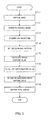
- FIG. 3 is a flowchart for explaining a detecting process by detection apparatus 100.
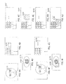
- Figs. 4 are image views for explaining various images.
- the processing flow shown in Fig. 3 starts with the start of an image capturing operation.
- the image capturing operation may be started by a user, or may be started with a signal from outside or the like as a trigger.
- first imaging section 101 and second imaging section 102 operate with synchronization section 103 to capture a face at the same timing from different viewpoints, and thereby acquire the first image and the second image.
- Figs. 4A and 4F respectively show the first image and the second image.
- a digital camera with a CMOS image sensor and a lens may be used as first imaging section 101 and second imaging section 102.
- PPM (Portable Pix Map file format) images or the like captured in synchronization with a projector are temporarily stored in image storage sections (e.g., a memory space of PC) in first imaging section 101 and second imaging section 102.
- the temporarily-stored images in the PPM file format are output to integral image calculation section 104.
- integral image calculation section 104 generates the integral images respectively from the first image and the second image.
- the first integral image is calculated from the first image
- the second integral image is calculated from the second image.
- Figs. 4B and 4G respectively show the first integral image and the second integral image.
- the first integral image and the second integral image are obtained by applying equation 1 to each pixel of the first image and the second image, and setting the calculation result as the value of each pixel.
- unit image acquisition section 105 acquires the "unit image pair" composed of the first unit image and the second unit image from the first integral image and the second integral image.
- Figs. 4C and 4H respectively show the first unit image (G151) and the second unit image (G152), which constitute one unit image pair.
- Unit image acquisition section 105 acquires, from the first integral image and the second integral image, the plurality of unit image pairs cut out at different positions from each other, by sequentially shifting the cutout positions of the unit images.
- the first unit image and the second unit image respectively correspond to partial images of the first image and the second image in which the same photographic object is captured. That is, there is parallax between the first imaging system and the second imaging system.
- the coordinates of the first unit image and the coordinates of the second unit image are separated from each other by a distance corresponding to the parallax. For example, in the case of a stereo camera, the distance is calculated from the approximate depth of an object by use of a calibration result obtained in advance.
- cross region pattern setting section 106 sequentially sets the constituent patterns with respect to each of the unit image pairs so as to set all the constituent patterns of the first cross region pattern group.
- the first cross region pattern group is composed of the M cross region patterns (M is a natural number not less than 2).
- the M cross region patterns (M is a natural number not less than 2) include a cross region pattern, of which all the constituent regions are set in the first unit image, a cross region pattern, of which all the constituent regions are set in the second unit image, and a cross region pattern, of which part of the constituent regions is set in the first unit image and the rest of the constituent regions is set in the second unit image.
- the respective regions of the cross region pattern preferably have a rectangular shape so as to obtain a speed-up effect by the integral image.
- the regions are not limited to the rectangular shape, and may have a circular shape, a triangular shape, or a closed curve shape.
- the shapes of the respective regions of the cross region pattern may not be the same as each other.
- Figs. 4E and 4J show a state in which a cross region pattern composed of region A161 and region A162 is applied to the first unit image and the second unit image.
- region A161 is set in the first unit image
- region A162 is set in the second unit image.
- the respective regions constituting the cross region pattern have a rectangular shape.
- Figs. 4D and 4I show a state in which regions A161 and A162 are set in partial images (G171 and G172) of the first image and the second image corresponding to the first unit image and the second unit image for the sake of convenience.
- feature value calculation section 107 calculates the feature value in each of the image regions where the cross region patterns are set by cross region pattern setting section 106, and calculates the total feature value for each of the cross region patterns.
- the calculated value associated with the total feature value for each of the cross region patterns is obtained through steps ST15 to 17 below.
- step ST15 feature value calculation section 107 calculates the feature value (i.e., region feature value) in each of the image regions where the cross region patterns are set by cross region pattern setting section 106.
- the region feature value is a value calculated by using the brightness values of pixels in each region.
- the region feature value is a sum, an average, or a median of the brightness values in the region.
- the above D is used as the region feature value so as to speed up the processing.
- step ST16 feature value calculation section 107 calculates a cross feature value V for each of the cross region patterns by performing algebra operation by use of the region feature values of each of the cross region patterns calculated in step ST15.
- the cross feature value V can be obtained, for example, by any of the following equations.
- step ST17 feature value calculation section 107 calculates a quantized cross feature value Q as the total feature value by quantizing the cross feature value V.
- the quantization is an operation to convert the cross feature value as a scalar value to a bin having a value within a predetermined range so as to perform data processing at high speed.
- the quantization is performed, for example, by the following equation 3.
- detection section 108 detects the center of a pupil as the object to be detected based on the total feature value for each of the constituent patterns of the first cross region pattern group, and the strong classifier composed of the plurality of weak classifiers stored in classifier storage section 112.
- the pupil center is searched by applying the strong classifier to each of the unit images by assuming that the center of the unit image is the pupil center.
- the center of a unit image to which the strong classifier gives a highest score is determined as the pupil center.
- Fig. 5 is a flowchart for explaining a learning process by detection apparatus 100.
- step ST21 the plurality of sample unit image pairs as learning samples are input to cross region pattern setting section 109.
- cross region pattern setting section 109 sequentially sets the constituent patterns with respect to each of the sample unit image pairs so as to set all the constituent patterns of the second cross region pattern group.
- the second cross region pattern group is composed of K cross region patterns (K is a natural number not less than M).
- step ST23 feature value calculation section 110 calculates the feature value in each of the image regions where the cross region patterns are set by cross region pattern setting section 109, and calculates the total feature value for each of the cross region patterns from the calculated feature values.
- the processing in step ST23 is the same processing as those of steps ST15 to 17.
- step ST24 feature learning section 111 generates at least one weak classifier candidate corresponding to each of the K cross region patterns constituting the second cross region pattern group.
- step ST25 feature learning section 111 extracts the weak classifier candidate that meets the "extraction standard" based on the total feature value for each of the K cross region patterns and the weak classifier candidate corresponding to each of the cross region patterns.
- classifier storage section 112 stores the weak classifier candidate output from feature learning section 111 as the weak classifier constituting the strong classifier.
- Figs. 6 show partial images of an image in which a person is captured.
- Figs. 6A to 6C are images of the same person captured under the same environment. However, since the head pose or the eyeball direction of the person differs in Figs. 6A to 6C , the red-eye effect occurs at different positions or with different intensities.
- pupils are detected by (1) searching the pupil contour as a circular or oval shape on an image, or (2) performing pattern recognition by learning the image of an eye region.
- the method (1) has a problem that the contour is difficult to acquire from the image
- the method (2) has a problem that there are various pupil flashing positions and intensity patterns to frequently cause false detection.
- Respective features (P201 to P215) in Fig. 7 are expressed as rectangular features composed of a white region and a black region.
- the features are called Haar-like features (e.g. see Non-Patent Literature 1).
- a value obtained by subtracting the sum of pixel values in the white region from the sum of pixel values in the black region of each of the rectangular features in Fig. 7 is treated as a feature value.
- detection apparatus 100 employs, as the feature, a difference in appearance between the images captured by the two imaging systems with different viewpoints. Accordingly, even when the red-eye effect partially occurs in the pupil, the pupil and its center, which are difficult to detect in a conventional method, can be detected.
- the cross region patterns set in the integral images with different constituent regions are used for calculating the feature value.
- the feature value calculated as described above is used, even the object to be detected, which appears differently depending on the position of the imaging apparatus, such as the pupil where the red-eye effect occurs, can be reliably detected.
- cross region pattern setting section 106 sequentially sets the plurality of "cross region patterns" with respect to each of the unit image pairs.
- Feature value calculation section 107 calculates the feature value in each of the image regions where the cross region patterns are set by cross region pattern setting section 106, and calculates the total feature value for each of the cross region patterns from the calculated feature values.
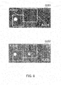
- Fig. 8 illustrates images for explaining the cross region pattern.
- region candidates A303 to A306 are set in partial images (G301 and G302) of the first image and the second image corresponding to the first unit image and the second unit image for the sake of convenience.
- a cross region pattern I is composed of regions A303 and A304.
- a cross region pattern 2 is composed of regions A303 and A305.
- a cross region pattern 3 is composed of regions A303 and A306.
- a cross region pattern 4 is composed of regions A304 and A305.
- a cross region pattern 5 is composed of regions A304 and A306.
- a cross region pattern 6 is composed of regions A305 and A306.
- Fig. 8 the same position on a face is captured in regions A303 and A305, and regions A304 and A306, respectively.
- regions A303 and A305 appear almost the same
- the images in region A304 and region A306 appear differently at a pupil portion.
- regions A303 and A304 which are set in the same image, flashes, there are flashing circles, though with different brightness levels, in both regions A305 and A306.
- the feature value can provide information which would not be obtained by the cross region pattern, of which all the constituent regions are set in the same image.
- many feature values based on the cross region patterns as described above are collected and learned. Consequently, the pupil where the red-eye effect occurs can be detected by pattern recognition.
- the quantized cross feature value Q calculated by feature value calculation section 107 by quantizing the cross feature value V is used in the above description, the present invention is not limited thereto.
- the cross feature value V may be used as the total feature value.
- unit image acquisition section 105 acquires, from each of the first integral image and the second integral image, the plurality of unit image pairs cut out at different positions from each other, by sequentially shifting the cutout positions of the unit images.
- Cross region pattern setting section 106 sequentially sets the constituent patterns with respect to each of the unit image pairs so as to set all the constituent patterns of the first cross region pattern group.
- Each of the cross region patterns is defined by the positions (i.e., the coordinates on the unit image plane) and the sizes of N regions (N is a natural number not less than 2) within the respective unit images, and the setting image information indicating whether the respective regions are set within the first unit image or the second unit image.
- Feature value calculation section 107 calculates the feature value in each of the image regions where the cross region patterns are set by cross region pattern setting section 106, and calculates the total feature value for each of the cross region patterns from the calculated feature values.
- Detection section 108 detects the object to be detected based on the total feature value for each of the constituent patterns of the first cross region pattern group, and the strong classifier composed of the plurality of weak classifiers stored in classifier storage section 112.
- the difference in appearance between the images captured by the two imaging systems with different viewpoints can be employed as the feature.
- the object to be detected which is difficult to detect in the conventional method (e.g., the pupil where the red-eye effect partially occurs, and its center), can be thereby detected.
- a pre-processing section that performs "pre-processing" on the first image and the second image may be provided on the input side of integral image calculation section 104.
- the "pre-processing” means processing such as smoothing, contrast adjustment, histogram normalization, and denoising on the first image and the second image.
- cross region pattern setting section 106 and cross region pattern setting section 109 are described as separate functional sections. However, cross region pattern setting section 106 and cross region pattern setting section 109 may be provided as a single functional section. Similarly, feature value calculation section 107 and feature value calculation section 110 may be provided as a single functional section.
- detection apparatus 100 may include CPU as a control section, ROM where a control program is recorded, RAM for program execution, a camera as an imaging apparatus, a projector, and a display section as a display and alarm apparatus, and the control section may control the operation of each section of detection apparatus 100.
- the respective section in Fig. 2 shows a line-of-sight determining process executed by the control section as blocks.
- Detection apparatus 100 may be effectively used as information terminals such as personal computers, office automation equipment, and mobiles, or an information provision apparatus mounted in transportations such as automobiles, airplanes, ships, and trains. Detection apparatus 100 may be also applied to monitoring or alarming apparatuses, robots, or audio/video reproduction apparatuses.
- the detection apparatus and the detection method according to the present invention can stably detect an object to be detected even when the object to be detected is captured in images differently and in various ways depending on the relative positional relationship between the object to be detected and the imaging apparatus.
Landscapes
- Engineering & Computer Science (AREA)
- General Physics & Mathematics (AREA)
- Physics & Mathematics (AREA)
- Multimedia (AREA)
- Theoretical Computer Science (AREA)
- General Health & Medical Sciences (AREA)
- Human Computer Interaction (AREA)
- Health & Medical Sciences (AREA)
- Ophthalmology & Optometry (AREA)
- Computer Vision & Pattern Recognition (AREA)
- Oral & Maxillofacial Surgery (AREA)
- Image Analysis (AREA)
- Collating Specific Patterns (AREA)
Abstract
Description
- The present invention relates to a detection apparatus and a detection method, and more particularly, to a detection apparatus and a detection method for detecting an object to be detected by use of stereo images captured by two imaging systems at the same timing.
- When the centers of pupils are detected in line-of-sight detection or expression detection, the red-eye effect may occur due to low illuminance. In a normal pupil detection method, pupils are detected by using a fact that the brightness of a portion corresponding to a pupil is normally lower than the brightness of a region around the portion in an image. However, when the red-eye effect occurs, the brightness of an image region corresponding to a pupil increases. Thus, when the red-eye effect occurs, pupils cannot be stably detected by the pupil detection method targeted at normal pupils.
- To solve the problem, in a technique disclosed in Patent Literature 1, pupils are detected by using a plurality of images captured at different timings while positively causing the red-eye effect to occur over the entire pupil.
- Japanese Patent Application Laid-Open No.
2005-182247 - Paul Viola and Michael J. Jones, "Rapid Object Detection using a Boosted Cascade of Simple Features", IEEE CVPR, 2001
- However, in the aforementioned conventional technique, the red-eye effect does not occur over the entire pupil, but occurs only in a portion of the pupil in some cases. In this case, only "a partial region of the pupil" where the red-eye effect occurs can be detected in the aforementioned conventional technique. The position of "a partial region of the pupil" where the red-eye effect occurs largely depends on the line of sight, the positional relationship between an imaging apparatus and a face, or the like. Thus, even if "a partial region of the pupil" where the red-eye effect occurs can be detected, the center position of the pupil is difficult to identify from the detection result.
- It is an object of the present invention to provide a detection apparatus and a detection method which can stably detect an object to be detected even when the object to be detected is captured in images differently and in various ways depending on the relative positional relationship between the object to be detected and an imaging apparatus.
- A detection apparatus reflecting one aspect of the present invention is a detection apparatus for detecting an object to be detected in a first image and a second image captured by two imaging systems at a same timing, including: an integral image calculation section that calculates a first integral image and a second integral image from the first image and the second image; an acquisition section that acquires a unit image pair composed of a first unit image and a second unit image from the first integral image and the second integral image, wherein a plurality of unit image pairs cut out at different positions from each other are acquired by sequentially shifting the cutout positions of the unit images; a setting section that sets, with respect to each of the unit image pairs, M cross region patterns (M is a natural number not less than 2), each of the M cross region patterns being defined by positions and sizes of N setting regions (N is a natural number not less than 2) within the respective unit images, and setting image information indicating whether the respective setting regions are set within the first unit image or the second unit image; a feature value calculation section that calculates a feature value in each of the image regions where the cross region patterns are set by the setting section, and calculates a total feature value for each of the cross region patterns from the calculated feature values; and a detection section that detects the object to be detected based on the total feature value for each of the M cross region patterns and a strong classifier composed of a plurality of weak classifiers each corresponding to each of the M cross region patterns.
- A detection method reflecting one aspect of the present invention is a detection method for detecting an object to be detected in a first image and a second image captured by two imagine systems at a same timing, including: an integral image calculation step of calculating a first integral image and a second integral image from the first image and the second image; an acquisition step of acquiring a unit image pair composed of a first unit image and a second unit image from the first integral image and the second integral image, wherein a plurality of unit image pairs cut out at different positions from each other are acquired by sequentially shifting the cutout positions of the unit images; a setting step of setting, with respect to each of the unit image pairs, M cross region patterns (M is a natural number not less than 2), each of the M cross region patterns being defined by positions and sizes of N setting regions (N is a natural number not less than 2) within the respective unit images, and setting image information indicating whether the respective setting regions are set within the first unit image or the second unit image; a feature value calculation step of calculating a feature value in each of the image regions where the cross region patterns are set in the setting step, and calculating a total feature value for each of the cross region patterns from the calculated feature values; and a detection step of detecting the object to be detected based on the total feature value for each of the M cross region patterns and a strong classifier composed of a plurality of weak classifiers each corresponding to each of the M cross region patterns.
- The present invention can provide a detection apparatus and a detection method which can stably detect an object to be detected even when the object to be detected is captured in images differently and in various ways depending on the relative positional relationship between the object to be detected and an imaging apparatus.
-
-
Fig. 1 is a block diagram illustrating the main configuration of a detection apparatus according to one embodiment of the present invention; -
Fig. 2 is a block diagram illustrating the configuration of the detection apparatus according to one embodiment of the present invention; -
Fig. 3 is a flowchart for explaining a detecting process by the detection apparatus; -
Figs. 4A-4J are image views for explaining various images; -
Fig. 5 is a flowchart for explaining a learning process by the detection apparatus; -
Figs. 6A-6D show partial images of an image in which a person is captured; -
Fig. 7 illustrates an example of a feature used in conventional cases; and -
Fig. 8 illustrates images for explaining a cross region pattern. - In the following, one embodiment of the present invention will be described in detail by reference to the drawings.
-
Fig. 1 shows the main configuration ofdetection apparatus 100 according to one embodiment of the present invention. InFig. 1 ,detection apparatus 100 includes integralimage calculation section 104, unitimage acquisition section 105, cross regionpattern setting section 106, featurevalue calculation section 107, anddetection section 108. - Integral
image calculation section 104 calculates a "first integral image" and a "second integral image" from a first image and a second image as stereo images captured by two imaging systems at the same timing. The "integral image" is a data structure for effectively calculating the sum of pixel values in a given rectangular region. The integral image calculated from the first image captured by a first imaging system is the "first integral image", and the integral image calculated from the second image captured by a second imaging system is the "second integral image". - Unit
image acquisition section 105 acquires unit images having a predetermined size from the first integral image and the second integral image. In the Following, the unit image acquired from the first integral image is called "first unit image", and the unit image acquired from the second integral image is called "second unit image". That is, unitimage acquisition section 105 acquires a "unit image pair" composed of the first unit image and the second unit image respectively from the first integral image and the second integral image. - The first unit image and the second unit image respectively correspond to partial images of the first image and the second image in which the same photographic object is captured. That is, there is parallax between the first imaging system and the second imaging system. Thus, when the same coordinate system is set for the first image and the second image, the coordinates of the first unit image and the coordinates of the second unit image are separated from each other by a distance corresponding to the parallax.
- Unit
image acquisition section 105 acquires the unit images respectively from the first integral image and the second integral image by sequentially shifting cutout positions of the unit images. Unitimage acquisition section 105 can thereby acquire a plurality of unit image pairs cut out at different positions from each other. - Cross region
pattern setting section 106 sequentially sets a plurality of "cross region patterns" with respect to each of the unit image pairs. Each of the cross region patterns is defined by the positions (i.e., the coordinates on a unit image plane) and the sizes of N regions (N is a natural number not less than 2) within the respective unit images, and setting image information indicating whether the respective regions are set within the first unit image or the second unit image. The unit image plane coordinates of a region constituting one cross region pattern differ from the unit image plane coordinates of a region constituting another cross region pattern. - Feature
value calculation section 107 calculates a feature value in each of the image regions where the cross region patterns are set by cross regionpattern setting section 106, and calculates a total feature value for each of the cross region patterns from the calculated feature values. -
Detection section 108 detects an object to be detected based on the total feature value for each of the plurality of cross region patterns, and a strong classifier composed of a plurality of weak classifiers each corresponding to each of the plurality of cross region patterns. - In the following, a case in which a human face is a photographic object and the center of a pupil is an object to be detected will be described as an example.
-
Fig. 2 shows the configuration ofdetection apparatus 100 according to one embodiment of the present invention. InFig. 2 ,detection apparatus 100 includesfirst imaging section 101,second imaging section 102,synchronization section 103, integralimage calculation section 104, unitimage acquisition section 105, cross regionpattern setting section 106, featurevalue calculation section 107,detection section 108, cross regionpattern setting section 109, featurevalue calculation section 110,feature learning section 111, andclassifier storage section 112. -
First imaging section 101 receives a synchronous signal output fromsynchronization section 103, and captures a human face at a timing according to the synchronous signal. An image captured by first imaging section 101 (simply referred to as "first image") is output to integralimage calculation section 104. -
First imaging section 101 is installed at a place, such as on a television, on an automobile steering wheel, and on a dashboard, where the imaging section easily captures a face.First imaging section 101 also includes an image sensor such as CCD (Charge Coupled Devices) and CMOS (Complementary Metal Oxide Semiconductor). -
Second imaging section 102 has the same configuration as that offirst imaging section 101. That is,second imaging section 102 receives a synchronous signal output fromsynchronization section 103, and captures the human face at a timing according to the synchronous signal.First imaging section 101 andsecond imaging section 102 can thereby capture the human face at the same timing. -
Second imaging section 102 is installed at a position apart a predetermined distance fromfirst imaging section 101 and where the imaging section can capture the same photographic object as that offirst imaging section 101. An image captured by second imaging section 102 (simply referred to as "second image") is output to integralimage calculation section 104. That is, the first image and the second image are images of the same photographic object captured at the same timing from different directions. - In the following, the captured first and second images will be described by setting the image horizontal direction as X axis, the image vertical direction as Y axis, and one pixel as one coordinate point.
-
Synchronization section 103 outputs the synchronous signals tofirst imaging section 101 andsecond imaging section 102.Synchronization section 103 outputs the synchronous signals for a time length equivalent to that from an exposure start to an exposure end, for example.First imaging section 101 andsecond imaging section 102 can thereby capture an object at the same timing. A trigger signal for the output of the synchronous signals may be manually given tosynchronization section 103 by a user, or may be automatically given tosynchronization section 103. -
First imaging section 101,second imaging section 102, andsynchronization section 103 described above are mounted as, for example, a stereo camera, and capture the face at the synchronized timing from different viewpoints. That is, the positional relationship betweenfirst imaging section 101 andsecond imaging section 102 is fixed and does not change in each image capturing operation as described above. - Integral
image calculation section 104 calculates an integral image from each of the first image and the second image input thereto. The integral image calculated from the first image is a first integral image, and the integral image calculated from the second image is a second integral image. - Unit
image acquisition section 105 acquires a "unit image pair" composed of a first unit image and a second unit image from the first integral image and the second integral image. - Unit
image acquisition section 105 acquires, from each of the first integral image and the second integral image, a plurality of unit image pairs cut out at different positions from each other, by sequentially shifting the cutout positions of the unit images. - Cross region
pattern setting section 106 sequentially sets a plurality of "cross region patterns" with respect to each of the unit image pairs. - To be more specific, cross region
pattern setting section 106 holds a first cross region pattern group. The first cross region pattern group is composed of the M cross region patterns (M is a natural number not less than 2). Cross regionpattern setting section 106 sequentially sets the constituent patterns with respect to each of the unit image pairs so as to set all the constituent patterns of the first cross region pattern group. - Feature
value calculation section 107 calculates a feature value in each of the image regions where the cross region patterns are set by cross regionpattern setting section 106, and calculates a total feature value for each of the cross region patterns from the calculated feature values. -
Detection section 108 detects an object to be detected based on the total feature value for each of the constituent patterns of the first cross region pattern group, and a strong classifier composed of a plurality of weak classifiers stored inclassifier storage section 112. Each of the plurality of weak classifiers constituting the strong classifier corresponds to each of the plurality of cross region patterns constituting the first cross region pattern group. That is, since the first cross region pattern group is composed of the M cross region patterns (M is a natural number not less than 2), the number of weak classifiers constituting the strong classifier is also M. - A plurality of sample unit image pairs as learning samples are input to cross region
pattern setting section 109. The plurality of sample unit image pairs include a positive sample and a negative sample. A sample unit image pair falling into the positive sample is composed of a first unit image and a second unit image calculated from a first image and a second image in which the center of a pupil is captured in the center of the unit image. A sample unit image pair falling into the negative sample is composed of a first unit image and a second unit image in which the center of a pupil is captured at a position other than the center of the unit image, or a first unit image and a second unit image in which no pupil center is captured. That is, the sample unit image pair falling into the negative sample is composed of unit images corresponding to a portion apart a predetermined distance from the pupil image. - Cross region
pattern setting section 109 sequentially sets a plurality of "cross region patterns" with respect to each of the sample unit image pairs. To be more specific, cross regionpattern setting section 109 holds a second cross region pattern group. The second cross region pattern group is composed of K cross region patterns (K is a natural number not less than M). Cross regionpattern setting section 109 sequentially sets the constituent patterns with respect to each of the sample unit image pairs so as to set all the constituent patterns of the second cross region pattern group. - Feature
value calculation section 110 calculates a feature value in each of image regions where the cross region patterns are set by cross regionpattern setting section 109, and calculates a total feature value for each of the cross region patterns from the calculated feature values. -
Feature learning section 111 generates at least one weak classifier candidate corresponding to each of the K cross region patterns constituting the second cross region pattern group. Here, the weak classifier is expressed as a function which, for example, returns 1 when the feature value is equal to or more than the predetermined threshold value and returns -1 when the feature value is less than the predetermined threshold value. One weak classifier corresponds to one cross region pattern. Thus, each of the weak classifiers is identified by the positions (i.e., the coordinates on a unit image plane) and the sizes of N regions (N is a natural number not less than 2) within the respective unit images, setting image information indicating whether the respective regions are set within the first unit image or the second unit image, and the predetermined threshold value. -
Feature learning section 111 extracts (determines) a weak classifier candidate that meets an "extraction standard" based on the total feature value for each of the K cross region patterns, and the weak classifier candidate corresponding to each of the cross region patterns. The accuracy rate in determining whether the weak classifier candidate is the positive sample or the negative sample is used as the "extraction standard".Feature learning section 111 outputs the weak classifier candidate meeting the extraction standard toclassifier storage section 112. -
Classifier storage section 112 stores the weak classifier candidate output fromfeature learning section 111 as a weak classifier constituting the strong classifier. In an early stage,classifier storage section 112 stores the weak classifier candidate output fromfeature learning section 111 as the weak classifier constituting the strong classifier. When the strong classifier has already been stored,classifier storage section 112 overwrites the existing weak classifier, which has already been stored as the weak classifier corresponding to the weak classifier candidate, with the new weak classifier candidate. Here, the strong classifier is expressed as a function which outputs the sum of scores obtained by the plurality of weak classifiers constituting the strong classifier. - The operation of
detection apparatus 100 having the above configuration will be described.Fig. 3 is a flowchart for explaining a detecting process bydetection apparatus 100.Figs. 4 are image views for explaining various images. The processing flow shown inFig. 3 starts with the start of an image capturing operation. The image capturing operation may be started by a user, or may be started with a signal from outside or the like as a trigger. - In step ST11,
first imaging section 101 andsecond imaging section 102 operate withsynchronization section 103 to capture a face at the same timing from different viewpoints, and thereby acquire the first image and the second image.Figs. 4A and 4F respectively show the first image and the second image. To be more specific, for example, a digital camera with a CMOS image sensor and a lens may be used asfirst imaging section 101 andsecond imaging section 102. PPM (Portable Pix Map file format) images or the like captured in synchronization with a projector are temporarily stored in image storage sections (e.g., a memory space of PC) infirst imaging section 101 andsecond imaging section 102. The temporarily-stored images in the PPM file format are output to integralimage calculation section 104. - In step ST12, integral
image calculation section 104 generates the integral images respectively from the first image and the second image. The first integral image is calculated from the first image, and the second integral image is calculated from the second image.Figs. 4B and 4G respectively show the first integral image and the second integral image. - To be more specific, the first integral image and the second integral image are obtained by applying equation 1 to each pixel of the first image and the second image, and setting the calculation result as the value of each pixel.
- [1]

- Here, a sum D of brightness values of any rectangular shape in the first integral image or the second integral image can be quickly obtained by equation 2.
- [2]

- In step ST13, unit
image acquisition section 105 acquires the "unit image pair" composed of the first unit image and the second unit image from the first integral image and the second integral image.Figs. 4C and 4H respectively show the first unit image (G151) and the second unit image (G152), which constitute one unit image pair. Unitimage acquisition section 105 acquires, from the first integral image and the second integral image, the plurality of unit image pairs cut out at different positions from each other, by sequentially shifting the cutout positions of the unit images. - The first unit image and the second unit image respectively correspond to partial images of the first image and the second image in which the same photographic object is captured. That is, there is parallax between the first imaging system and the second imaging system. When the same coordinate system is set for the first image and the second image, the coordinates of the first unit image and the coordinates of the second unit image are separated from each other by a distance corresponding to the parallax. For example, in the case of a stereo camera, the distance is calculated from the approximate depth of an object by use of a calibration result obtained in advance.
- In step ST14, cross region
pattern setting section 106 sequentially sets the constituent patterns with respect to each of the unit image pairs so as to set all the constituent patterns of the first cross region pattern group. The first cross region pattern group is composed of the M cross region patterns (M is a natural number not less than 2). - The M cross region patterns (M is a natural number not less than 2) include a cross region pattern, of which all the constituent regions are set in the first unit image, a cross region pattern, of which all the constituent regions are set in the second unit image, and a cross region pattern, of which part of the constituent regions is set in the first unit image and the rest of the constituent regions is set in the second unit image. The respective regions of the cross region pattern preferably have a rectangular shape so as to obtain a speed-up effect by the integral image. However, the regions are not limited to the rectangular shape, and may have a circular shape, a triangular shape, or a closed curve shape. The shapes of the respective regions of the cross region pattern may not be the same as each other. The sizes of the respective regions of the cross region pattern may be the same as or different from each other.
Figs. 4E and 4J show a state in which a cross region pattern composed of region A161 and region A162 is applied to the first unit image and the second unit image. As to the cross region pattern, region A161 is set in the first unit image, and region A162 is set in the second unit image. The respective regions constituting the cross region pattern have a rectangular shape.Figs. 4D and 4I show a state in which regions A161 and A162 are set in partial images (G171 and G172) of the first image and the second image corresponding to the first unit image and the second unit image for the sake of convenience. - Subsequently, feature
value calculation section 107 calculates the feature value in each of the image regions where the cross region patterns are set by cross regionpattern setting section 106, and calculates the total feature value for each of the cross region patterns. - To be more specific, the calculated value associated with the total feature value for each of the cross region patterns is obtained through steps ST15 to 17 below.
- In step ST15, feature
value calculation section 107 calculates the feature value (i.e., region feature value) in each of the image regions where the cross region patterns are set by cross regionpattern setting section 106. The region feature value is a value calculated by using the brightness values of pixels in each region. For example, the region feature value is a sum, an average, or a median of the brightness values in the region. Here, the above D is used as the region feature value so as to speed up the processing. - In step ST16, feature
value calculation section 107 calculates a cross feature value V for each of the cross region patterns by performing algebra operation by use of the region feature values of each of the cross region patterns calculated in step ST15. - When each of the cross region patterns has two regions (a region 1 and a region 2) as the constituent regions, and the region feature value of the region 1 is X and the region feature value of the region 2 is Y, the cross feature value V can be obtained, for example, by any of the following equations.


- In step ST17, feature
value calculation section 107 calculates a quantized cross feature value Q as the total feature value by quantizing the cross feature value V. The quantization is an operation to convert the cross feature value as a scalar value to a bin having a value within a predetermined range so as to perform data processing at high speed. The quantization is performed, for example, by the following equation 3. - [3]

- In step ST18,
detection section 108 detects the center of a pupil as the object to be detected based on the total feature value for each of the constituent patterns of the first cross region pattern group, and the strong classifier composed of the plurality of weak classifiers stored inclassifier storage section 112. The pupil center is searched by applying the strong classifier to each of the unit images by assuming that the center of the unit image is the pupil center. The center of a unit image to which the strong classifier gives a highest score is determined as the pupil center. -
Fig. 5 is a flowchart for explaining a learning process bydetection apparatus 100. - In step ST21, the plurality of sample unit image pairs as learning samples are input to cross region
pattern setting section 109. - In step ST22, cross region
pattern setting section 109 sequentially sets the constituent patterns with respect to each of the sample unit image pairs so as to set all the constituent patterns of the second cross region pattern group. The second cross region pattern group is composed of K cross region patterns (K is a natural number not less than M). - In step ST23, feature
value calculation section 110 calculates the feature value in each of the image regions where the cross region patterns are set by cross regionpattern setting section 109, and calculates the total feature value for each of the cross region patterns from the calculated feature values. The processing in step ST23 is the same processing as those of steps ST15 to 17. - In step ST24,
feature learning section 111 generates at least one weak classifier candidate corresponding to each of the K cross region patterns constituting the second cross region pattern group. - In step ST25,
feature learning section 111 extracts the weak classifier candidate that meets the "extraction standard" based on the total feature value for each of the K cross region patterns and the weak classifier candidate corresponding to each of the cross region patterns. - In step ST26,
classifier storage section 112 stores the weak classifier candidate output fromfeature learning section 111 as the weak classifier constituting the strong classifier. - In a case in which a face is illuminated from a close distance of 1 m or less and thereby captured in an image, such a phenomenon that the pupil partially flashes occurs. The phenomenon occurs in various modes depending on the positional relationship between a projector and an imaging apparatus, the head pose, the eyeball direction, or the like. It is thus not easy to estimate the flashing position within the pupil in advance.
Figs. 6 show partial images of an image in which a person is captured.Figs. 6A to 6C are images of the same person captured under the same environment. However, since the head pose or the eyeball direction of the person differs inFigs. 6A to 6C , the red-eye effect occurs at different positions or with different intensities. In a case in which the person is captured by using a near-infrared image, it is difficult to estimate the pupil center from the iris contour due to little brightness difference between the white and the iris. Moreover, when the red-eye effect unevenly occurs, there is only a small brightness difference between the dark portion and the iris of the pupil in most cases, and the pupil contour is thus difficult to detect. Furthermore, when the person as a photographic object wears glasses as shown inFig. 6D , circular reflection similar to the red-eye effect may occur due to lens reflection. Since recognition by color phase is impossible in the near-infrared image, the lens reflection is frequently detected as the pupil by mistake. - In a typical pupil detection method, pupils are detected by (1) searching the pupil contour as a circular or oval shape on an image, or (2) performing pattern recognition by learning the image of an eye region. However, when the red-eye effect partially occurs as in the present invention, the method (1) has a problem that the contour is difficult to acquire from the image, and the method (2) has a problem that there are various pupil flashing positions and intensity patterns to frequently cause false detection.
- In a case in which a feature is extracted from an image captured by a typical imaging apparatus, a combination of adjacent regions within one image is often obtained as the feature as shown in
Fig. 7 . The feature is not generated between different images. This is because an object often has different positions or poses in different images, and a significant feature is thus difficult to express. Respective features (P201 to P215) inFig. 7 are expressed as rectangular features composed of a white region and a black region. The features are called Haar-like features (e.g. see Non-Patent Literature 1). A value obtained by subtracting the sum of pixel values in the white region from the sum of pixel values in the black region of each of the rectangular features inFig. 7 is treated as a feature value. - On the other hand,
detection apparatus 100 according to the present embodiment employs, as the feature, a difference in appearance between the images captured by the two imaging systems with different viewpoints. Accordingly, even when the red-eye effect partially occurs in the pupil, the pupil and its center, which are difficult to detect in a conventional method, can be detected. - To be more specific, in the present embodiment, the cross region patterns set in the integral images with different constituent regions are used for calculating the feature value. When the feature value calculated as described above is used, even the object to be detected, which appears differently depending on the position of the imaging apparatus, such as the pupil where the red-eye effect occurs, can be reliably detected.
- To be more specific, cross region
pattern setting section 106 sequentially sets the plurality of "cross region patterns" with respect to each of the unit image pairs. Featurevalue calculation section 107 calculates the feature value in each of the image regions where the cross region patterns are set by cross regionpattern setting section 106, and calculates the total feature value for each of the cross region patterns from the calculated feature values. -
Fig. 8 illustrates images for explaining the cross region pattern. InFig. 8 , region candidates (A303 to A306) are set in partial images (G301 and G302) of the first image and the second image corresponding to the first unit image and the second unit image for the sake of convenience. - When the cross region pattern is generated by using the region candidates, six cross region patterns can be generated. A cross region pattern I is composed of regions A303 and A304. A cross region pattern 2 is composed of regions A303 and A305. A cross region pattern 3 is composed of regions A303 and A306. A cross region pattern 4 is composed of regions A304 and A305. A cross region pattern 5 is composed of regions A304 and A306. A cross region pattern 6 is composed of regions A305 and A306.
- In
Fig. 8 , the same position on a face is captured in regions A303 and A305, and regions A304 and A306, respectively. However, while the images in region A303 and region A305 appear almost the same, the images in region A304 and region A306 appear differently at a pupil portion. While only one of regions A303 and A304, which are set in the same image, flashes, there are flashing circles, though with different brightness levels, in both regions A305 and A306. - When the feature value is calculated by using the cross region pattern, of which part of the constituent regions is set in the first unit image and the rest of the constituent regions is set in the second unit image, the feature value can provide information which would not be obtained by the cross region pattern, of which all the constituent regions are set in the same image. In the present embodiment, many feature values based on the cross region patterns as described above are collected and learned. Consequently, the pupil where the red-eye effect occurs can be detected by pattern recognition.
- Although the quantized cross feature value Q calculated by feature
value calculation section 107 by quantizing the cross feature value V is used in the above description, the present invention is not limited thereto. The cross feature value V may be used as the total feature value. - As described above, in
detection apparatus 100 of the present embodiment, unitimage acquisition section 105 acquires, from each of the first integral image and the second integral image, the plurality of unit image pairs cut out at different positions from each other, by sequentially shifting the cutout positions of the unit images. Cross regionpattern setting section 106 sequentially sets the constituent patterns with respect to each of the unit image pairs so as to set all the constituent patterns of the first cross region pattern group. Each of the cross region patterns is defined by the positions (i.e., the coordinates on the unit image plane) and the sizes of N regions (N is a natural number not less than 2) within the respective unit images, and the setting image information indicating whether the respective regions are set within the first unit image or the second unit image. Featurevalue calculation section 107 calculates the feature value in each of the image regions where the cross region patterns are set by cross regionpattern setting section 106, and calculates the total feature value for each of the cross region patterns from the calculated feature values.Detection section 108 detects the object to be detected based on the total feature value for each of the constituent patterns of the first cross region pattern group, and the strong classifier composed of the plurality of weak classifiers stored inclassifier storage section 112. - Accordingly, the difference in appearance between the images captured by the two imaging systems with different viewpoints can be employed as the feature. The object to be detected, which is difficult to detect in the conventional method (e.g., the pupil where the red-eye effect partially occurs, and its center), can be thereby detected.
- In
detection apparatus 100 shown inFig. 2 , a pre-processing section that performs "pre-processing" on the first image and the second image may be provided on the input side of integralimage calculation section 104. The "pre-processing" means processing such as smoothing, contrast adjustment, histogram normalization, and denoising on the first image and the second image. - In
detection apparatus 100 shown inFig. 2 , cross regionpattern setting section 106 and cross regionpattern setting section 109 are described as separate functional sections. However, cross regionpattern setting section 106 and cross regionpattern setting section 109 may be provided as a single functional section. Similarly, featurevalue calculation section 107 and featurevalue calculation section 110 may be provided as a single functional section. - The functions of the above respective sections may be achieved by a microcomputer executing a control program. That is,
detection apparatus 100 may include CPU as a control section, ROM where a control program is recorded, RAM for program execution, a camera as an imaging apparatus, a projector, and a display section as a display and alarm apparatus, and the control section may control the operation of each section ofdetection apparatus 100. The respective section inFig. 2 shows a line-of-sight determining process executed by the control section as blocks. -
Detection apparatus 100 may be effectively used as information terminals such as personal computers, office automation equipment, and mobiles, or an information provision apparatus mounted in transportations such as automobiles, airplanes, ships, and trains.Detection apparatus 100 may be also applied to monitoring or alarming apparatuses, robots, or audio/video reproduction apparatuses. - The disclosure of Japanese Patent Application No.
2011-004788, filed on January 13, 2011 - The detection apparatus and the detection method according to the present invention can stably detect an object to be detected even when the object to be detected is captured in images differently and in various ways depending on the relative positional relationship between the object to be detected and the imaging apparatus.
-
- 100 Detection apparatus
- 101 First imaging section
- 102 Second imaging section
- 103 Synchronization section
- 104 Integral image calculation section
- 105 Unit image acquisition section
- 106, 109 Cross region pattern setting section
- 107, 110 Feature value calculation section
- 108 Detection section
- 111 Feature learning section
- 112 Classifier storage section
Claims (4)
- A detection apparatus for detecting an object to be detected in a first image and a second image captured by two imaging systems at a same timing, comprising:an integral image calculation section that calculates a first integral image and a second integral image from the first image and the second image;an acquisition section that acquires a unit image pair composed of a first unit image and a second unit image, from the first integral image and the second integral image, wherein a plurality of unit image pairs cut out at different positions from each other are acquired by sequentially shifting the cutout positions of the unit images;a setting section that sets, with respect to each of the unit image pairs, M cross region patterns (M is a natural number not less than 2), each of the M cross region patterns being defined by positions and sizes of N setting regions (N is a natural number not less than 2) within the respective unit images, and setting image information indicating whether the respective setting regions are set within the first unit image or the second unit image;a feature value calculation section that calculates a feature value in each of the image regions where the cross region patterns are set by the setting section, and calculates a total feature value for each of the cross region patterns from the calculated feature values; anda detection section that detects the object to be detected based on the total feature value for each of the M cross region patterns and a strong classifier composed of a plurality of weak classifiers each corresponding to each of the M cross region patterns.
- The detection apparatus according to claim 1, wherein the setting section sets a cross region pattern group composed of K cross region patterns (K is a natural number not less than M) with respect to each of a plurality of sample unit image pairs input thereto,
the feature value calculation section calculates a feature value in each of image regions where the cross region patterns constituting the cross region pattern group are set by the setting section, and calculates a total feature value for each of the cross region patterns from the calculated feature values, and
the detection apparatus further comprises a determination section that determines the weak classifier based on the total feature value for each of the K cross region patterns, and a weak classifier candidate corresponding to each of the cross region patterns constituting the cross region pattern group. - The detection apparatus according to claim 1, wherein the feature value calculation section performs algebra operation by use of the calculated feature values to calculate the total feature value.
- A detection method for detecting an object to be detected in a first image and a second image captured by two imaging systems at a same timing, comprising:an integral image calculation step of calculating a first integral image and a second integral image from the first image and the second image;an acquisition step of acquiring a unit image pair composed of a first unit image and a second unit image from the first integral image and the second integral image, wherein a plurality of unit image pairs cut out at different positions from each other are acquired by sequentially shifting the cutout positions of the unit images;a setting step of setting, with respect to each of the unit image pairs, M cross region patterns (M is a natural number not less than 2), each of the M cross region patterns being defined by positions and sizes of N setting regions (N is a natural number not less than 2) within the respective unit images, and setting image information indicating whether the respective setting regions are set within the first unit image or the second unit image;a feature value calculation step of calculating a feature value in each of the image regions where the cross region patterns are set in the setting step, and calculating a total feature value for each of the cross region patterns from the calculated feature values; anda detection step of detecting the object to be detected based on the total feature value for each of the M cross region patterns and a strong classifier composed of a plurality of weak classifiers each corresponding to each of the M cross region patterns.
Applications Claiming Priority (2)
| Application Number | Priority Date | Filing Date | Title |
|---|---|---|---|
| JP2011004788A JP5603258B2 (en) | 2011-01-13 | 2011-01-13 | Detection apparatus and detection method |
| PCT/JP2011/007108 WO2012095927A1 (en) | 2011-01-13 | 2011-12-20 | Detection device and detection method |
Publications (2)
| Publication Number | Publication Date |
|---|---|
| EP2665036A1 true EP2665036A1 (en) | 2013-11-20 |
| EP2665036A4 EP2665036A4 (en) | 2017-10-11 |
Family
ID=46506854
Family Applications (1)
| Application Number | Title | Priority Date | Filing Date |
|---|---|---|---|
| EP11855890.7A Withdrawn EP2665036A4 (en) | 2011-01-13 | 2011-12-20 | Detection device and detection method |
Country Status (5)
| Country | Link |
|---|---|
| US (1) | US9082002B2 (en) |
| EP (1) | EP2665036A4 (en) |
| JP (1) | JP5603258B2 (en) |
| CN (1) | CN103026383B (en) |
| WO (1) | WO2012095927A1 (en) |
Families Citing this family (2)
| Publication number | Priority date | Publication date | Assignee | Title |
|---|---|---|---|---|
| KR101503788B1 (en) * | 2013-12-27 | 2015-03-19 | 숭실대학교산학협력단 | Pedestrian detection method using estimation of feature information based on integral image, recording medium and terminal for performing the method |
| CN111914858A (en) * | 2020-08-17 | 2020-11-10 | 浙江大华技术股份有限公司 | Method and apparatus for determining characteristic value, storage medium, and electronic apparatus |
Family Cites Families (17)
| Publication number | Priority date | Publication date | Assignee | Title |
|---|---|---|---|---|
| JP2541688B2 (en) | 1990-05-21 | 1996-10-09 | 日産自動車株式会社 | Eye position detection device |
| US7155035B2 (en) * | 2002-02-05 | 2006-12-26 | Matsushita Electric Industrial Co., Ltd. | Personal authentication method, personal authentication apparatus and image capturing device |
| US7206435B2 (en) * | 2002-03-26 | 2007-04-17 | Honda Giken Kogyo Kabushiki Kaisha | Real-time eye detection and tracking under various light conditions |
| WO2003102498A1 (en) | 2002-05-30 | 2003-12-11 | Visx, Inc. | “tracking torsional eye orientation and position” |
| JP4166143B2 (en) * | 2002-11-21 | 2008-10-15 | 株式会社国際電気通信基礎技術研究所 | Face position extraction method, program for causing computer to execute face position extraction method, and face position extraction apparatus |
| JP4839432B2 (en) | 2003-12-17 | 2011-12-21 | 国立大学法人静岡大学 | Pointing device and method based on pupil position detection |
| US20050201591A1 (en) * | 2004-03-10 | 2005-09-15 | Kiselewich Stephen J. | Method and apparatus for recognizing the position of an occupant in a vehicle |
| JP2005258860A (en) * | 2004-03-12 | 2005-09-22 | Matsushita Electric Ind Co Ltd | Multiple authentication method and apparatus |
| JP4568836B2 (en) * | 2004-06-08 | 2010-10-27 | 国立大学法人静岡大学 | Real-time pupil position detection system |
| CN1680779A (en) | 2005-02-04 | 2005-10-12 | 江苏大学 | Driver fatigue monitoring method and device |
| EP1850270B1 (en) * | 2006-04-28 | 2010-06-09 | Toyota Motor Europe NV | Robust interest point detector and descriptor |
| CN101641720B (en) | 2007-01-23 | 2014-01-29 | 蒙特·拉姆斯特德 | Wide color gamut anaglyphs |
| JP5025292B2 (en) * | 2007-03-12 | 2012-09-12 | 株式会社東芝 | Suspicious person detection system and method |
| JP2008261756A (en) * | 2007-04-12 | 2008-10-30 | National Institute Of Information & Communication Technology | Apparatus and program for estimating a three-dimensional head posture in real time from a pair of stereo images |
| JP5045212B2 (en) * | 2007-04-25 | 2012-10-10 | 株式会社デンソー | Face image capturing device |
| JP5393287B2 (en) | 2009-06-23 | 2014-01-22 | 株式会社平和 | Game machine |
| CN101901485B (en) | 2010-08-11 | 2014-12-03 | 华中科技大学 | 3D free head moving type gaze tracking system |
-
2011
- 2011-01-13 JP JP2011004788A patent/JP5603258B2/en active Active
- 2011-12-20 CN CN201180036460.4A patent/CN103026383B/en active Active
- 2011-12-20 EP EP11855890.7A patent/EP2665036A4/en not_active Withdrawn
- 2011-12-20 US US13/816,395 patent/US9082002B2/en active Active
- 2011-12-20 WO PCT/JP2011/007108 patent/WO2012095927A1/en not_active Ceased
Non-Patent Citations (1)
| Title |
|---|
| See references of WO2012095927A1 * |
Also Published As
| Publication number | Publication date |
|---|---|
| US9082002B2 (en) | 2015-07-14 |
| JP2012146175A (en) | 2012-08-02 |
| CN103026383B (en) | 2015-09-30 |
| JP5603258B2 (en) | 2014-10-08 |
| US20130142416A1 (en) | 2013-06-06 |
| WO2012095927A1 (en) | 2012-07-19 |
| CN103026383A (en) | 2013-04-03 |
| EP2665036A4 (en) | 2017-10-11 |
Similar Documents
| Publication | Publication Date | Title |
|---|---|---|
| US8983235B2 (en) | Pupil detection device and pupil detection method | |
| JP4307496B2 (en) | Facial part detection device and program | |
| EP2164027B1 (en) | Object detecting device, imaging apparatus, object detecting method, and program | |
| US9020209B2 (en) | Face identification device | |
| US9646215B2 (en) | Eye part detection apparatus | |
| EP2012255B1 (en) | Image processing apparatus and image processing method | |
| US20160140399A1 (en) | Object detection apparatus and method therefor, and image recognition apparatus and method therefor | |
| KR20140036803A (en) | System for generating signcription of wireless mobie communication | |
| JP2017010224A (en) | Object tracking apparatus, object tracking method, and program | |
| JP2008146172A (en) | Eye detection device, eye detection method, and program | |
| US11227152B2 (en) | Recognition apparatus, recognition method, and recognition program | |
| KR101399785B1 (en) | Method and apparatus for detecting, capturing face image for face recognition | |
| US9082002B2 (en) | Detection device and detection method | |
| JP2007072627A (en) | Sunglasses detection device and face center position detection device | |
| JP6866182B2 (en) | Bed positioning device | |
| JP5061563B2 (en) | Detection apparatus, biological determination method, and program | |
| KR101669447B1 (en) | System and the method for recognizing drowsiness | |
| US20100014751A1 (en) | Image processing device, storage medium, and image processing method | |
| KR101087250B1 (en) | Face detection device using skin color area detection | |
| Naba et al. | Haar-like feature based real-time neuro car detection system | |
| JP6847708B2 (en) | Bed positioning device | |
| CN110890156A (en) | Device, method and computer storage medium for facial glossiness classification | |
| EP3611655B1 (en) | Object detection based on analysis of a sequence of images | |
| Singh et al. | Drowsy Driver Detection System |
Legal Events
| Date | Code | Title | Description |
|---|---|---|---|
| PUAI | Public reference made under article 153(3) epc to a published international application that has entered the european phase |
Free format text: ORIGINAL CODE: 0009012 |
|
| 17P | Request for examination filed |
Effective date: 20130215 |
|
| AK | Designated contracting states |
Kind code of ref document: A1 Designated state(s): AL AT BE BG CH CY CZ DE DK EE ES FI FR GB GR HR HU IE IS IT LI LT LU LV MC MK MT NL NO PL PT RO RS SE SI SK SM TR |
|
| DAX | Request for extension of the european patent (deleted) | ||
| RAP1 | Party data changed (applicant data changed or rights of an application transferred) |
Owner name: PANASONIC INTELLECTUAL PROPERTY CORPORATION OF AME |
|
| RA4 | Supplementary search report drawn up and despatched (corrected) |
Effective date: 20170911 |
|
| RIC1 | Information provided on ipc code assigned before grant |
Ipc: G06K 9/46 20060101ALI20170905BHEP Ipc: G06T 7/00 20170101AFI20170905BHEP Ipc: G06K 9/00 20060101ALI20170905BHEP |
|
| 17Q | First examination report despatched |
Effective date: 20190722 |
|
| STAA | Information on the status of an ep patent application or granted ep patent |
Free format text: STATUS: THE APPLICATION HAS BEEN WITHDRAWN |
|
| 18W | Application withdrawn |
Effective date: 20191030 |