EP2665007A1 - Simulation method for polymer material comprising filler - Google Patents
Simulation method for polymer material comprising filler Download PDFInfo
- Publication number
- EP2665007A1 EP2665007A1 EP13163174.9A EP13163174A EP2665007A1 EP 2665007 A1 EP2665007 A1 EP 2665007A1 EP 13163174 A EP13163174 A EP 13163174A EP 2665007 A1 EP2665007 A1 EP 2665007A1
- Authority
- EP
- European Patent Office
- Prior art keywords
- filler
- particles
- models
- particle
- polymer
- Prior art date
- Legal status (The legal status is an assumption and is not a legal conclusion. Google has not performed a legal analysis and makes no representation as to the accuracy of the status listed.)
- Withdrawn
Links
Images




Classifications
-
- G—PHYSICS
- G06—COMPUTING OR CALCULATING; COUNTING
- G06F—ELECTRIC DIGITAL DATA PROCESSING
- G06F30/00—Computer-aided design [CAD]
- G06F30/20—Design optimisation, verification or simulation
- G06F30/25—Design optimisation, verification or simulation using particle-based methods
-
- G—PHYSICS
- G16—INFORMATION AND COMMUNICATION TECHNOLOGY [ICT] SPECIALLY ADAPTED FOR SPECIFIC APPLICATION FIELDS
- G16C—COMPUTATIONAL CHEMISTRY; CHEMOINFORMATICS; COMPUTATIONAL MATERIALS SCIENCE
- G16C20/00—Chemoinformatics, i.e. ICT specially adapted for the handling of physicochemical or structural data of chemical particles, elements, compounds or mixtures
- G16C20/30—Prediction of properties of chemical compounds, compositions or mixtures
-
- G—PHYSICS
- G06—COMPUTING OR CALCULATING; COUNTING
- G06F—ELECTRIC DIGITAL DATA PROCESSING
- G06F30/00—Computer-aided design [CAD]
- G06F30/20—Design optimisation, verification or simulation
-
- C—CHEMISTRY; METALLURGY
- C08—ORGANIC MACROMOLECULAR COMPOUNDS; THEIR PREPARATION OR CHEMICAL WORKING-UP; COMPOSITIONS BASED THEREON
- C08L—COMPOSITIONS OF MACROMOLECULAR COMPOUNDS
- C08L21/00—Compositions of unspecified rubbers
-
- C—CHEMISTRY; METALLURGY
- C08—ORGANIC MACROMOLECULAR COMPOUNDS; THEIR PREPARATION OR CHEMICAL WORKING-UP; COMPOSITIONS BASED THEREON
- C08L—COMPOSITIONS OF MACROMOLECULAR COMPOUNDS
- C08L2666/00—Composition of polymers characterized by a further compound in the blend, being organic macromolecular compounds, natural resins, waxes or and bituminous materials, non-macromolecular organic substances, inorganic substances or characterized by their function in the composition
- C08L2666/02—Organic macromolecular compounds, natural resins, waxes or and bituminous materials
-
- G—PHYSICS
- G01—MEASURING; TESTING
- G01N—INVESTIGATING OR ANALYSING MATERIALS BY DETERMINING THEIR CHEMICAL OR PHYSICAL PROPERTIES
- G01N33/00—Investigating or analysing materials by specific methods not covered by groups G01N1/00 - G01N31/00
- G01N33/44—Resins; Plastics; Rubber; Leather
- G01N33/445—Rubber
-
- G—PHYSICS
- G06—COMPUTING OR CALCULATING; COUNTING
- G06F—ELECTRIC DIGITAL DATA PROCESSING
- G06F30/00—Computer-aided design [CAD]
- G06F30/10—Geometric CAD
- G06F30/15—Vehicle, aircraft or watercraft design
-
- G—PHYSICS
- G16—INFORMATION AND COMMUNICATION TECHNOLOGY [ICT] SPECIALLY ADAPTED FOR SPECIFIC APPLICATION FIELDS
- G16C—COMPUTATIONAL CHEMISTRY; CHEMOINFORMATICS; COMPUTATIONAL MATERIALS SCIENCE
- G16C10/00—Computational theoretical chemistry, i.e. ICT specially adapted for theoretical aspects of quantum chemistry, molecular mechanics, molecular dynamics or the like
Definitions
- the present invention relates to a simulation method for a high polymer material capable of simulating and evaluating the dispersion of fillers in a high polymer material certainly at short times.
- High polymer materials such as compounded rubber used in vehicle tires usually contain fillers such as carbon black and silica. It is well known in the art that the dispersion of fillers in a compounded rubber exerts a strong influence on properties, e.g. strength of the rubber.
- filler models of fillers and polymer models of a high polymer material are defined, and a molecular dynamics (MD) calculation is performed on the filler models and polymer models placed or set in a predetermined virtual space. Then, based on results of the simulation, the dispersion of the fillers is evaluated by an operating personnel. Thus, it is difficult to provide objective exact evaluations. Further, it takes a long time to compute the movements of the filler models in order to simulate the filler dispersion.
- MD molecular dynamics
- an object of the present invention to provide a computerized simulation method for evaluating the dispersion of fillers in a high polymer material, by which the filler dispersion state can be simulated and evaluated certainly at short times.
- a computerized simulation method for evaluating the dispersion of fillers in a high polymer material comprises:
- a potential from the outside of the filler model acts on the most influential particle prior to any other filler particles.
- the most influential particle is taken as the representative point of the filler model. If migrations of the most influential particles are increased, the filler models can be considered as being dispersed widely. From the mean-square displacement, the extent of a movement of a most influential particle per unit time is obtained. Accordingly, the dispersion of the filler models can be grasped, therefore, the filler dispersion state can be evaluated reliably at short times.
- the simulation method according to the present invention is a method for simulating and evaluating the dispersion of fillers in a high polymer material by the use of a computer 1.
- high polymer material is intended to include at least rubber, resin and elastomer.
- filler is intended to include at least carbon black, silica and alumina.
- the computer 1 comprises a main body 1a, a keyboard 1b, a mouse 1c and a display 1d.
- the main body 1a comprises an arithmetic processing unit (CPU), ROM, work memory, storage devices such as magnetic disk, disk drives 1a1 and 1a2 and the like.
- CPU central processing unit
- ROM read-only memory
- storage devices such as magnetic disk, disk drives 1a1 and 1a2 and the like.
- programs/software for carrying out the simulating method are stored.
- Fig. 2 is a flowchart of the simulation method as an embodiment of the present invention.
- a filler model defining step S1 is implemented.
- step S1 as shown in Fig. 3 , filler models 3 of the fillers are defined, wherein each filler model 3 is defined to represent a plurality of filler particles 4 (e.g. carbon particles), and the filler particle 4 is a sphere having a certain diameter.
- filler particles 4 e.g. carbon particles
- the filler model 3 corresponds to numerical data (inclusive of the mass, volume, diameter and initial coordinates of each of the filler particles 4) necessary to deal with the fillers by the molecular dynamics. Such numerical data are entered and stored in the computer 1.
- the filler particles 4 constituting each filler model 3 are a single center filler particle 4c, and at least four in this example eight surface filler particles 4s, wherein the centers C of the surface filler particles 4s are positioned on a spherical surface B of which center coincides with the center of the center filler particle 4c.
- joining chains 4j on which equilibrium lengths are respectively defined.
- the equilibrium lengths are the bond distances between the center filler particle 4c and the surface filler particles 4s and between the surface filler particles 4s when the relative positions of the surface filler particle 4s on the spherical surface B become steady.
- the center filler particle 4c and the surface filler particles 4s are bonded, keeping their relative positions. Further, the center filler particle 4c and three or more surface filler particles 4s in each filler model 3 are arranged so as not to locate in the same plane or one plane.
- the surface filler particles 4s are positioned at the vertices of a polyhedron, and the center filler particle 4c is positioned at the center of the polyhedron.
- step S2 polymer models 5 of the high polymer material are defined.
- each polymer model 5 is defined to represent at least one polymer particle 6 preferably a plurality of polymer particles 6 of the high polymer material.
- the polymer model 5 corresponds to numerical data necessary to deal with the high polymer material by the molecular dynamics. Such numerical data are entered and stored in the computer 1.
- the polymer particles 6 of the polymer model 5 in this example include modified basal particles 6b and nonmodified particles 6a, and different potentials (after-mentioned) are defined for the particles 6a and particles 6b.
- Each of the particles 6a and 6b is a sphere having a certain diameter.
- joining chains 6j so as to keep them under restraint and to have a three dimensional structure like a straight-chain polymer.
- step S3 simulation conditions necessary for executing the subsequent molecular dynamics (MD) calculation are set.
- a potential defining step S3a is implemented.
- step S3a as shown in Fig. 5 , potentials are respectively defined between the filler particles 4c, 4s of a filler model 3 and the filler particles 4c, 4s of another filler model 3, between the filler particles 4c, 4s of a filler model 3 and the polymer particles 6a, 6b of a polymer model 5, and between the polymer particles 6a, 6b of a polymer model 5 and the polymer particles 6a, 6b of another polymer model 5.
- the potentials are stored in the computer 1 as numerical data, and used to calculate a force between the two particles concerned.
- the potential is a function of the distance between the concerned particles.
- the potential U is defined such that a mutual interaction (in this embodiment, a repulsive force) occurs if the distance r ij is decreased under the predefined cutoff distance r C . If the distance r ij is more than the cutoff distance r C , the potential U is zero and no repulsive force occurs between the particles.
- potentials U1-U10 are defined:
- a treatise J. Chem Phys. 107(11) 4423-4435 (1997 ) proposes that the strength a ij of potential between particles of the same kind is set to be 25.
- the strength a ij of the potentials U1-U10 are set as follows.
- Such modified basal particle 6b is increased in the affinity to the filler particle 4c, 4s, and therefore can simulate a denaturizing agent actually added in the high polymer material. Accordingly, by incorporating such modified basal particles 6b in the polymer model 5, the dispersion of the filler models 3 in the polymer models 5 can be changed, and it becomes possible to simulate a modified polymer.
- the cutoff distance r C is defined for each of the potentials U1-U10 as follows.
- one of the filler particles 4 of each filler model 3 is defined as a most influential particle 7. Further, the following three different cutoff distances r C are predefined:
- the center filler particle 4c of each filler model 3 is defined as the most influential particle 7. Therefore, the cutoff distance r C used for the potential (for example U7) between the center filler particle 4c of a filler models 3 and the center filler particle 4c of another filler model 3 is set to be larger than the cutoff distance r C used for the potential (for example, U8) between the surface filler particle 4s of a filler model 3 and the surface filler particle 4s of another filler model 3.
- the most influential particle 7 is a filler particle relating to the largest cutoff distance. Therefore, in a filler model 3, a potential from the outside of the filler model 3 acts on the most influential particle 7 (center filler particle 4c) prior to any other filler particles (surface filler particles 4s). Accordingly, the most influential particle 7 of the filler model 3 influences the motion of the filler model 3. Therefore, in the molecular dynamics calculation, it is possible to take the most influential particle 7 as the representative point of the filler model 3. If migrations of the most influential particles 7 are increased, the filler models 3 are considered as being dispersed widely.
- the large cutoff distance r C (potential U7) used between the most influential particles 7 and 7 is set to be more than the sum (r C + R) of the small cutoff distance r C (potential U8) between the particles 4 other than the most influential particle 7 (i.e. the surface filler particles 4s and 4s) and the radius R of the above-mentioned spherical surface B in order to assure that the potential acts on the most influential particle 7 prior to any other filler particles.
- the computer 1 can treat the filler models 3 as spheres like the actual filler.
- a step S3b is implemented, wherein, as shown in Fig. 7 , a virtual space V having a predetermined volume is defined and the filler models 3 and the polymer models 5 are disposed in the virtual space V.
- the virtual space V corresponds to a minute fraction of the actual high polymer material, e.g. polymer as the analysis object.
- the shape of the virtual space V is a regular hexahedron whose each side has a length L1 of from 20 to 40[ ⁇ ] for example. [ ⁇ ] is unit of length.
- the virtual space for example, 500 to 1500 filler models 3 and 1000 to 3000 polymer models 5 are initially randomly disposed.
- a simulation step S4 is implemented.
- a molecular dynamics calculation is performed.
- the molecular dynamics calculation is continued until the initial placement of the filler models 3 and polymer models 5 which is artificial, becomes not artificial (structure relaxation).
- a predetermined number for example 500 to 300000
- the number of all the particles existing in the system or the virtual space 8 and the volume and temperature of the system are kept constant.
- step S5a the mean-square displacement of the most influential particles 7 to be evaluated is computed.
- Fig. 9 shows an exemplary graph in which the values of the mean-square displacement computed at some time intervals, are plotted.
- the self-diffusion coefficient of the most influential particle 7 can be obtained. With the increase in the self-diffusion coefficient, the extent of a movement of the most influential particle 7 is increased. Therefore, based on whether the self-diffusion coefficient is large or nor, it is possible to judge whether the dispersion state of the filler models 3 is good or not. Thus, the dispersion state can be evaluated.
- the mean-square displacement of the most influential particle 7 is increased in proportion to the increase in the time.
- Such increase means that the extent of the movement is wide, namely, the dispersion is good.
- the dispersion of the filler model 3 can be evaluated and grasped certainly at short times.
- the mean-square displacement is computed at at least five time intervals.
- the number of plotted data is at least five (In the example shown in Fig. 9 , the number is 20). If the number is less than five, it is difficult to obtain the self-diffusion coefficient accurately, and there is a possibility that the dispersion state can not be grasped exactly. If the number exceeds 1000, the computational time increases. Therefore, the number of the time intervals is preferably set in a range of not less than 10 but not more than 100.
- step S5b the computer 1 judges whether the dispersion state of the filler models 3 is good or not, based on whether the obtained mean-square displacement is within a predetermined acceptable range or not.
- a molecular dynamics calculation on the filler models and polymer models was performed. Then, the mean-square displacement of the most influential particles, namely the center filler particles of the filler models, was computed. The result is shown in Fig. 10 as Embodiment.
Landscapes
- Engineering & Computer Science (AREA)
- Theoretical Computer Science (AREA)
- Physics & Mathematics (AREA)
- Computer Hardware Design (AREA)
- Evolutionary Computation (AREA)
- Geometry (AREA)
- General Engineering & Computer Science (AREA)
- General Physics & Mathematics (AREA)
- Chemical & Material Sciences (AREA)
- Crystallography & Structural Chemistry (AREA)
- Life Sciences & Earth Sciences (AREA)
- Bioinformatics & Cheminformatics (AREA)
- Bioinformatics & Computational Biology (AREA)
- Computing Systems (AREA)
- Management, Administration, Business Operations System, And Electronic Commerce (AREA)
- Compositions Of Macromolecular Compounds (AREA)
- Moulds For Moulding Plastics Or The Like (AREA)
Abstract
Description
- The present invention relates to a simulation method for a high polymer material capable of simulating and evaluating the dispersion of fillers in a high polymer material certainly at short times.
- High polymer materials such as compounded rubber used in vehicle tires usually contain fillers such as carbon black and silica. It is well known in the art that the dispersion of fillers in a compounded rubber exerts a strong influence on properties, e.g. strength of the rubber.
- In recent years, in order to evaluate the dispersion of fillers in a high polymer material, various computerized simulation (numerical calculation) methods have been proposed.
- In this kind of simulation method, filler models of fillers and polymer models of a high polymer material are defined, and a molecular dynamics (MD) calculation is performed on the filler models and polymer models placed or set in a predetermined virtual space.
Then, based on results of the simulation, the dispersion of the fillers is evaluated by an operating personnel. Thus, it is difficult to provide objective exact evaluations.
Further, it takes a long time to compute the movements of the filler models in order to simulate the filler dispersion. - It is therefore, an object of the present invention to provide a computerized simulation method for evaluating the dispersion of fillers in a high polymer material, by which the filler dispersion state can be simulated and evaluated certainly at short times.
- According to the present invention, a computerized simulation method for evaluating the dispersion of fillers in a high polymer material comprises:
- a filler model defining step in which filler models of the fillers are defined, wherein each of the filler models represents a plurality of filler particles;
- a polymer model defining step in which polymer models of the high polymer material are defined, wherein each of the polymer models represents one or more polymer particles;
- a simulation step in which a molecular dynamics calculation is performed for the polymer models and the filler models placed in a predetermined virtual space; and
- an evaluation step in which the state of dispersion of the filler models is evaluated from results obtained through the simulation step,
wherein - between the particles inclusive of the filler particles and the polymer particles, potentials such that when the distance between the concerned particles is decreased under a predefined cutoff distance, a mutual interaction occurs therebetween, are defined,
- one of the filler particles in each filler model is defined as a most influential particle for which a largest cutoff distance is defined, and
- the evaluation step includes a step in which a mean-square displacement of the most influential particles is computed.
- The method according to the present invention may be provided with the following features (I)-(III):
- (I) the filler particles of each filler model are a single center filler particle and at least four surface filler particles whose centers are positioned on a spherical surface whose center coincides with a center of the center filler particle,
equilibrium lengths are respectively defined between the center filler particle and the surface filler particles and between the surface filler particles, and
the center filler particle is the most influential particle; - (II) the cutoff distance between the center filler particles is larger than the sum of the radius of the above-mentioned spherical surface and the cutoff distance between the surface filler particles;
- (III) the evaluation step includes a step in which the mean-square displacement is computed at five or more time intervals.
- Therefore, in a filler model, a potential from the outside of the filler model acts on the most influential particle prior to any other filler particles. In the molecular dynamics calculation, the most influential particle is taken as the representative point of the filler model. If migrations of the most influential particles are increased, the filler models can be considered as being dispersed widely.
From the mean-square displacement, the extent of a movement of a most influential particle per unit time is obtained. Accordingly, the dispersion of the filler models can be grasped, therefore, the filler dispersion state can be evaluated reliably at short times. -
-
Fig. 1 is a perspective view of a computer system implementing a simulation method as an embodiment of the present invention. -
Fig. 2 is a flow chart of the simulation method in this embodiment. -
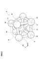
Fig. 3 is a diagram showing a filler model. -
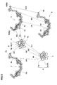
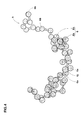
Fig. 4 is a diagram showing a polymer model. -
Fig. 5 is a diagram for explaining potentials of the filler particles and polymer particles. -
Fig. 6 is a diagram for explaining the cutoff distance of a filler particle. -
Fig. 7 is a perspective diagram for explaining a virtual space in which filler models and polymer models are disposed. -
Fig. 8 is a diagram for explaining the extent of a movement of a filler particle. -
Fig. 9 is an exemplary graph of the mean-square displacement of most influential particles. -
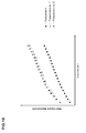
Fig. 10 is a graph in which the mean-square displacement computed by various methods are plotted. - An embodiment of present invention will now be described in detail in conjunction with accompanying drawings.
- The simulation method according to the present invention is a method for simulating and evaluating the dispersion of fillers in a high polymer material by the use of a
computer 1. Here, the term "high polymer material" is intended to include at least rubber, resin and elastomer.
The term "filler" is intended to include at least carbon black, silica and alumina. - As shown in
Fig. 1 for example, thecomputer 1 comprises amain body 1a, akeyboard 1b, a mouse 1c and adisplay 1d. Themain body 1a comprises an arithmetic processing unit (CPU), ROM, work memory, storage devices such as magnetic disk, disk drives 1a1 and 1a2 and the like. In the storage device, programs/software for carrying out the simulating method are stored. -
Fig. 2 is a flowchart of the simulation method as an embodiment of the present invention. - In this method, firstly, a filler model defining step S1 is implemented. In this step S1, as shown in
Fig. 3 ,filler models 3 of the fillers are defined, wherein eachfiller model 3 is defined to represent a plurality of filler particles 4 (e.g. carbon particles), and thefiller particle 4 is a sphere having a certain diameter. - Incidentally, the
filler model 3 corresponds to numerical data (inclusive of the mass, volume, diameter and initial coordinates of each of the filler particles 4) necessary to deal with the fillers by the molecular dynamics. Such numerical data are entered and stored in thecomputer 1. - The
filler particles 4 constituting eachfiller model 3 are a singlecenter filler particle 4c, and at least four in this example eightsurface filler particles 4s, wherein the centers C of thesurface filler particles 4s are positioned on a spherical surface B of which center coincides with the center of thecenter filler particle 4c. - In each
filler model 3, between thecenter filler particle 4c and thesurface filler particles 4s and also between thesurface filler particles 4s, there are provided joiningchains 4j on which equilibrium lengths are respectively defined. - Here, the equilibrium lengths are the bond distances between the
center filler particle 4c and thesurface filler particles 4s and between thesurface filler particles 4s when the relative positions of thesurface filler particle 4s on the spherical surface B become steady. - If the bond distance is changed, it revert to the equilibrium length by the
joining chain 4j so as to become a steady state. - In the
filler model 3 in this example, thecenter filler particle 4c and thesurface filler particles 4s are bonded, keeping their relative positions. Further, thecenter filler particle 4c and three or moresurface filler particles 4s in eachfiller model 3 are arranged so as not to locate in the same plane or one plane. Thesurface filler particles 4s are positioned at the vertices of a polyhedron, and thecenter filler particle 4c is positioned at the center of the polyhedron. - Next,
polymer models 5 of the high polymer material are defined. (step S2) - In this step S2, as shown in
Fig. 4 , eachpolymer model 5 is defined to represent at least onepolymer particle 6 preferably a plurality ofpolymer particles 6 of the high polymer material. - Incidentally, the
polymer model 5 corresponds to numerical data necessary to deal with the high polymer material by the molecular dynamics. Such numerical data are entered and stored in thecomputer 1. - The
polymer particles 6 of thepolymer model 5 in this example include modifiedbasal particles 6b andnonmodified particles 6a, and
different potentials (after-mentioned) are defined for theparticles 6a andparticles 6b.
Each of theparticles - Between the
particles chains 6j so as to keep them under restraint and to have a three dimensional structure like a straight-chain polymer. - Next, a simulation condition setting step S3 is implemented.
- In the step S3, simulation conditions necessary for executing the subsequent molecular dynamics (MD) calculation are set. In this embodiment, firstly, a potential defining step S3a is implemented.
- In this step S3a, as shown in
Fig. 5 , potentials are respectively defined between thefiller particles filler model 3 and thefiller particles filler model 3, between thefiller particles filler model 3 and thepolymer particles polymer model 5, and between thepolymer particles polymer model 5 and thepolymer particles polymer model 5. - The potentials are stored in the
computer 1 as numerical data, and used to calculate a force between the two particles concerned. Here, the potential is a function of the distance between the concerned particles. The potential U is given by the following expression (1):
where
aij is an invariable corresponding to the strength of the potential U defined between the particles concerned,
rij is the distance between the centers of the particles concerned, and
rC is the cutoff distance predefined between the particles concerned. - with the expression (1), the potential U is defined such that a mutual interaction (in this embodiment, a repulsive force) occurs if the distance rij is decreased under the predefined cutoff distance rC. If the distance rij is more than the cutoff distance rC, the potential U is zero and no repulsive force occurs between the particles.
- In this particular example, for the following combinations of two particles, potentials U1-U10 are defined:
-
particles 4c-6a: potential U1 -
particles 4c-6b: potential U2 -
particles 4c-4s: potential U3 -
particles 4s-6a: potential U4 -
particles 4s-6b: potential U5 -
particles 6a-6b: potential U6 -
particles 4c-4c: potential U7 -
particles 4s-4s: potential U8 -
particles 6a-6a: potential U9 -
particles 6b-6b: potential U10 - As to the strength aij of the potential, a treatise (J. Chem Phys. 107(11) 4423-4435 (1997)) proposes that the strength aij of potential between particles of the same kind is set to be 25.
- But, various researches made afterward (for example, Macromolcule vol.39 6744(2006)) suggest that the strength aij of potential between particles of the same kind is set to be 50, and the strength aij of potential between particles of the different kinds is set to be 72.
- In this example, by reference to these values, the strength aij of the potentials U1-U10 are set as follows.
- potential U1: aij=72
- potential U2: aij=25
- potential U3: aij=50
- potential U4: aij=72
- potential U5: aij=25
- potential U6: aij=72
- potential U7: aij=50
- potential U8: aij=50
- potential U9: aij=50
- potential U10: aij=50
- As above, the strength aij(=25) of the potential U2, U5 between the modified
basal particle 6b of thepolymer model 5 and thefiller particle filler model 3 is set to be smaller than the strength aij(=72) of the potential U1, U4 between thenonmodified particle 6a of thepolymer particle 6 and thefiller particle filler model 3, therefore, in comparison with thenonmodified particle 6a, the modifiedbasal particle 6b is decreased in the repulsive force. - Such modified
basal particle 6b is increased in the affinity to thefiller particle basal particles 6b in thepolymer model 5, the dispersion of thefiller models 3 in thepolymer models 5 can be changed, and it becomes possible to simulate a modified polymer. - In the expression (1), the cutoff distance rC is defined for each of the potentials U1-U10 as follows.
- potential U1: rC=3
- potential U2: rC=3
- potential U3: rC=3
- potential U4: rC=1
- potential U5: rC=1
- potential U6: rC=1
- potential U7: rC=5
- potential U8: rC=1
- potential U9: rC=1
- potential U10: rC=1
- According to the present invention, one of the
filler particles 4 of eachfiller model 3 is defined as a mostinfluential particle 7.
Further, the following three different cutoff distances rC are predefined: - a largest cutoff distance used between the most
influential particle 7 of afiller model 3 and the mostinfluential particle 7 of anotherfiller model 3; - a smallest cutoff distance used between any
particle 4 other than the mostinfluential particle 7 of afiller model 3 and anyparticle 4 other than the mostinfluential particle 7 of anotherfiller model 3; and - a middle cutoff distance used between the most
influential particle 7 of afiller model 3 and anyparticle 4 other than the mostinfluential particle 7 of anotherfiller model 3. - In this embodiment, the
center filler particle 4c of eachfiller model 3 is defined as the mostinfluential particle 7. Therefore, the cutoff distance rC used for the potential (for example U7) between thecenter filler particle 4c of afiller models 3 and thecenter filler particle 4c of anotherfiller model 3 is set to be larger than the cutoff distance rC used for the potential (for example, U8) between thesurface filler particle 4s of afiller model 3 and thesurface filler particle 4s of anotherfiller model 3. - The most
influential particle 7 is a filler particle relating to the largest cutoff distance. Therefore, in afiller model 3, a potential from the outside of thefiller model 3 acts on the most influential particle 7 (center filler particle 4c) prior to any other filler particles (surface filler particles 4s). Accordingly, the mostinfluential particle 7 of thefiller model 3 influences the motion of thefiller model 3. Therefore, in the molecular dynamics calculation, it is possible to take the mostinfluential particle 7 as the representative point of thefiller model 3.
If migrations of the mostinfluential particles 7 are increased, thefiller models 3 are considered as being dispersed widely. - It is desirable that, as shown in
Fig. 6 , the large cutoff distance rC (potential U7) used between the mostinfluential particles 7 and 7 (i.e. between thecenter filler particles particles 4 other than the most influential particle 7 (i.e. thesurface filler particles influential particle 7 prior to any other filler particles. - Between the most
influential particles 7, the potential acts radially. Therefore, in the molecular dynamics calculation, thecomputer 1 can treat thefiller models 3 as spheres like the actual filler. - Next, a step S3b is implemented, wherein, as shown in
Fig. 7 , a virtual space V having a predetermined volume is defined and thefiller models 3 and thepolymer models 5 are disposed in the virtual space V. - The virtual space V corresponds to a minute fraction of the actual high polymer material, e.g. polymer as the analysis object.
- In this embodiment, the shape of the virtual space V is a regular hexahedron whose each side has a length L1 of from 20 to 40[σ] for example. [σ] is unit of length.
In the virtual space, for example, 500 to 1500filler models 3 and 1000 to 3000polymer models 5 are initially randomly disposed. - Next, a simulation step S4 is implemented. In this step S4, a molecular dynamics calculation is performed.
- In the molecular dynamics calculation, assuming that all of the
filler models 3 and thepolymer models 5 in the virtual space V follow the classical dynamics, the calculation is made according to Newton's equation of motion for a given time period, and the motion of each of thefiller particles polymer particles - In this embodiment, the molecular dynamics calculation is continued until the initial placement of the
filler models 3 andpolymer models 5 which is artificial, becomes not artificial (structure relaxation).
As an example, when the number of the time steps reaches to a predetermined number (for example 500 to 300000), the molecular dynamics calculation is ended. - During making the molecular dynamics calculation, the number of all the particles existing in the system or the virtual space 8 and the volume and temperature of the system are kept constant.
- Next, an evaluation step 55 is implemented.
- In this step S5, from results obtained in the simulation step S4, the dispersion state of the
filler models 3 is evaluated. For this, firstly, a step S5a is implemented. In this step, the mean-square displacement of the mostinfluential particles 7 to be evaluated is computed.
The mean-square displacement (MSD) is given by the following expression (2):
where - r(0) is the coordinate of the
center 7c of a most influential particle at a given time point, - r(t) is the coordinate of the
center 7c of the most influential particle at a time interval of length t after the given time point, and - <...> denotes an ensemble average over the predetermined most
influential particles 7 and over some time intervals. - In the expression (2), |r(t)-r(0)| is the (vector) distance traveled by the most
influential particle 7 over the time interval of length t as shown inFig. 8 .
The obtaining of the value of the MSD allows to grasp the extent of a movement of the mostinfluential particle 7.
As noted above, in the molecular dynamics calculation, the mostinfluential particle 7 is taken as the representative point of thefiller model 3.
Therefore, from the value of the MSD, the extent of a movement of thefiller model 3 can be grasped. -
Fig. 9 shows an exemplary graph in which the values of the mean-square displacement computed at some time intervals, are plotted. - From the slope θ of the regression line Lr to the mean-square displacement, the self-diffusion coefficient of the most
influential particle 7 can be obtained.
with the increase in the self-diffusion coefficient, the extent of a movement of the mostinfluential particle 7 is increased. Therefore, based on whether the self-diffusion coefficient is large or nor, it is possible to judge whether the dispersion state of thefiller models 3 is good or not. Thus, the dispersion state can be evaluated. - In
Fig. 9 , the mean-square displacement of the mostinfluential particle 7 is increased in proportion to the increase in the time. Such increase means that the extent of the movement is wide, namely, the dispersion is good. - In this way, without the need for computing the mean-square displacement of the
surface filler particle 4s, the dispersion of thefiller model 3 can be evaluated and grasped certainly at short times. - For that purpose, it is desirable that the mean-square displacement is computed at at least five time intervals.
In other words, the number of plotted data is at least five (In the example shown inFig. 9 , the number is 20).
If the number is less than five, it is difficult to obtain the self-diffusion coefficient accurately, and there is a possibility that the dispersion state can not be grasped exactly. If the number exceeds 1000, the computational time increases.
Therefore, the number of the time intervals is preferably set in a range of not less than 10 but not more than 100. - Next, a step S5b is implemented. In this step S5b, the
computer 1 judges whether the dispersion state of thefiller models 3 is good or not, based on whether the obtained mean-square displacement is within a predetermined acceptable range or not. - In this embodiment, if the dispersion state of the
filler models 3 is judged as good, the simulation is ended. - On the other hand, if the dispersion state is judged as not good, taking the obtained mean-square displacement into consideration, the conditions previously set on the
filler models 3 and thepolymer models 5 are changed, and again the simulation is implemented. Such operation is repeated to find out conditions in which thefiller models 3 are well dispersed. - According to the flowchart shown in
Fig. 2 , a molecular dynamics calculation on the filler models and polymer models was performed. Then, the mean-square displacement of the most influential particles, namely the center filler particles of the filler models, was computed. The result is shown inFig. 10 as Embodiment. - Further, for comparison, the mean-square displacement of all of the filler particles of the filler models was computed.
The result is shown inFig. 10 as Comparative example 1. - Furthermore, the mean-square displacement of all of the surface filler particles of the filler models was computed. The result is shown in
Fig. 10 as Comparative example 2. - The details of the filler models, polymer models and potentials were as described above. Other common specifications are as follows:
- The length L1 of each side of the virtual space was 30 [σ].
- The number of the filler models in the virtual space was 100.
- The number of the polymer models in the virtual space was 1500.
- The number of the time steps of the molecular dynamics calculation was 100000.
- The mean-square displacement was computed at twenty time intervals.
- In addition, without using the positions of the filler particles obtained in the molecular dynamics calculation as above, the positions of the gravity points of the respective filler models were computed, and the mean-square displacement of the gravity points was computed. (as Experimental example in Table 1)
- Then, with respect to the mean-square displacement, the Embodiment, Comparative example 1, Comparative example 2 and Experimental example were compared. The results are shown in Table 1.
- Further, as to the computational time, embodiment, comparative example 1,comparative example 2 and experimental example were compared. The results are shown in Table 1.
Table 1 Method Experimental example Embodiment Comparative example 1 Comparative example 2 Mean-square displacement 1.08 1.05 3.01 3.48 Computational time (hour) 9.90 1.10 9.88 8.75 - From the comparison of the mean-square displacement, it was confirmed that the Embodiment can simulate the filler dispersion state close to that by the Experimental example, therefore, a reliable evaluation is possible.
Further, in the Embodiment, it was not necessary to compute the gravity points as in the Experimental example, therefore, the computational time was remarkably reduced.
Claims (4)
- A computerized simulation method for evaluating the dispersion of fillers in a high polymer material comprising:a filler model defining step in which filler models of the fillers are defined, wherein each of the filler models represents a plurality of filler particles;a polymer model defining step in which polymer models of the high polymer material are defined, wherein each of the polymer models represents one or more polymer particles;a simulation step in which a molecular dynamics calculation is performed for the polymer models and the filler models placed in a predetermined virtual space; andan evaluation step in which the state of dispersion of the filler models is evaluated from results obtained through the simulation step,
whereinbetween the particles inclusive of the filler particles and the polymer particles, potentials such that when the distance between the concerned particles is decreased under a predefined cutoff distance, a mutual interaction occurs therebetween, are defined,one of the filler particles in each filler model is defined as a most influential particle for which a largest cutoff distance is defined, andthe evaluation step includes a step in which a mean-square displacement of the most influential particles is computed. - The simulation method according to claim 1, wherein
the filler particles of each filler model are a single center filler particle and at least four surface filler particles whose centers are positioned on a spherical surface whose center coincides with a center of the center filler particle,
equilibrium lengths are respectively defined between the center filler particle and the surface filler particles and between the surface filler particles, and
the center filler particle is the most influential particle. - The simulation method according to claim 2, wherein
the cutoff distance between the center filler particles is larger than the sum of the radius of the above-mentioned spherical surface and the cutoff distance between the surface filler particles. - The simulation method according to claim 1, 2 or 3, wherein
the evaluation step includes a step in which the mean-square displacement is computed at five or more time intervals.
Applications Claiming Priority (1)
| Application Number | Priority Date | Filing Date | Title |
|---|---|---|---|
| JP2012112678A JP5466727B2 (en) | 2012-05-16 | 2012-05-16 | Method for simulating polymer materials |
Publications (1)
| Publication Number | Publication Date |
|---|---|
| EP2665007A1 true EP2665007A1 (en) | 2013-11-20 |
Family
ID=48325371
Family Applications (1)
| Application Number | Title | Priority Date | Filing Date |
|---|---|---|---|
| EP13163174.9A Withdrawn EP2665007A1 (en) | 2012-05-16 | 2013-04-10 | Simulation method for polymer material comprising filler |
Country Status (4)
| Country | Link |
|---|---|
| US (1) | US9477794B2 (en) |
| EP (1) | EP2665007A1 (en) |
| JP (1) | JP5466727B2 (en) |
| CN (1) | CN103425815B (en) |
Cited By (2)
| Publication number | Priority date | Publication date | Assignee | Title |
|---|---|---|---|---|
| CN103678814A (en) * | 2013-12-18 | 2014-03-26 | 北京航空航天大学 | Method for designing eccentricity ratio prebias of critical inclination nearly-circular orbit |
| CN103853887A (en) * | 2014-03-05 | 2014-06-11 | 北京航空航天大学 | Satellite orbit determination method for eccentricity of frozen orbit |
Families Citing this family (9)
| Publication number | Priority date | Publication date | Assignee | Title |
|---|---|---|---|---|
| JP5602190B2 (en) * | 2012-06-08 | 2014-10-08 | 住友ゴム工業株式会社 | Method for simulating polymer materials |
| US20140067350A1 (en) * | 2012-08-31 | 2014-03-06 | Sumitomo Rubber Industries, Ltd. | Method for simulating polymer material |
| JP6360392B2 (en) * | 2014-09-04 | 2018-07-18 | 住友ゴム工業株式会社 | Method for simulating polymer materials |
| JP6408874B2 (en) * | 2014-11-14 | 2018-10-17 | 住友ゴム工業株式会社 | Method for simulating modified polymer materials |
| JP6050903B1 (en) * | 2016-01-22 | 2016-12-21 | 住友ゴム工業株式会社 | Method for simulating polymer materials |
| JP6891548B2 (en) * | 2017-03-08 | 2021-06-18 | 横浜ゴム株式会社 | Composite material analysis model creation method, composite material analysis model creation computer program, composite material analysis method and composite material analysis computer program |
| CN109580431B (en) * | 2019-01-28 | 2021-06-29 | 贵州电网有限责任公司 | SF (sulfur hexafluoride)6/N2Method for determining diffusion characteristics of mixed gas |
| JP7613170B2 (en) * | 2021-03-11 | 2025-01-15 | 住友ゴム工業株式会社 | How to create a filler model |
| CN114664390B (en) * | 2022-05-23 | 2022-09-13 | 苏州创腾软件有限公司 | Method and system for generating cross-linked polymer space network structure in simulation mode |
Family Cites Families (11)
| Publication number | Priority date | Publication date | Assignee | Title |
|---|---|---|---|---|
| EP1163639A4 (en) * | 1999-01-27 | 2006-08-09 | Scripps Research Inst | COMPRESSING IMAGE DATA IN CONNECTION WITH TWO-DIMENSIONAL ARRANGEMENTS OF PICTORIAL PART COMPONENTS |
| JP3660932B2 (en) * | 2003-11-17 | 2005-06-15 | 住友ゴム工業株式会社 | Rubber material simulation method |
| EP1526468B1 (en) * | 2003-10-17 | 2009-09-30 | Sumitomo Rubber Industries Limited | Method of simulating viscoelastic material |
| JP4053994B2 (en) * | 2004-01-22 | 2008-02-27 | 住友ゴム工業株式会社 | Simulation method for interaction between fillers |
| JP4093994B2 (en) * | 2004-07-01 | 2008-06-04 | 横浜ゴム株式会社 | Simulation method for heterogeneous materials |
| JP4533045B2 (en) | 2004-08-30 | 2010-08-25 | 住友ゴム工業株式会社 | Evaluation method of rubber materials |
| JP4594043B2 (en) * | 2004-11-15 | 2010-12-08 | 住友ゴム工業株式会社 | Rubber material simulation method |
| JP5169225B2 (en) * | 2007-05-25 | 2013-03-27 | 横浜ゴム株式会社 | COMPOSITE MATERIAL MODEL CREATION DEVICE, SIMULATION DEVICE, COMPOSITE MATERIAL MODEL CREATION PROGRAM, AND COMPOSITE MATERIAL MODEL CREATION DEVICE OPERATION METHOD |
| JP5169278B2 (en) * | 2008-02-14 | 2013-03-27 | 横浜ゴム株式会社 | Operation method of composite material model creating apparatus, operation method of simulation apparatus for deformation behavior of composite material, and composite material simulation apparatus |
| JP5432549B2 (en) * | 2009-03-05 | 2014-03-05 | 住友ゴム工業株式会社 | Rubber material simulation method |
| JP2011248541A (en) * | 2010-05-25 | 2011-12-08 | Bridgestone Corp | Simulation method of intermolecular force |
-
2012
- 2012-05-16 JP JP2012112678A patent/JP5466727B2/en not_active Expired - Fee Related
-
2013
- 2013-04-09 US US13/859,035 patent/US9477794B2/en not_active Expired - Fee Related
- 2013-04-10 EP EP13163174.9A patent/EP2665007A1/en not_active Withdrawn
- 2013-05-09 CN CN201310169324.3A patent/CN103425815B/en active Active
Non-Patent Citations (5)
| Title |
|---|
| ALLEGRA G ET AL: "Theories and simulations of polymer-based nanocomposites: From chain statistics to reinforcement", PROGRESS IN POLYMER SCIENCE, PERGAMON PRESS, OXFORD, GB, vol. 33, no. 7, 1 July 2008 (2008-07-01), pages 683 - 731, XP023906890, ISSN: 0079-6700, [retrieved on 20080304], DOI: 10.1016/J.PROGPOLYMSCI.2008.02.003 * |
| D. BROWN ET AL: "Effect of Filler Particle Size on the Properties of Model Nanocomposites", MACROMOLECULES, vol. 41, no. 4, 1 February 2008 (2008-02-01), pages 1499 - 1511, XP055082941, ISSN: 0024-9297, DOI: 10.1021/ma701940j * |
| J. CHEM PHYS., vol. 107, no. 11, 1997, pages 4423 - 4435 |
| MACROMOLCULE, vol. 39, 2006, pages 6744 |
| RAOS G ET AL: "Nonequilibrium simulations of filled polymer networks: Searching for the origins of reinforcement and nonlinearity", JOURNAL OF CHEMICAL PHYSICS, AMERICAN INSTITUTE OF PHYSICS, NEW YORK, NY, US, vol. 134, no. 5, 7 February 2011 (2011-02-07), pages 54902/1 - 14, XP009172858, ISSN: 0021-9606, DOI: 10.1063/1.3537971 * |
Cited By (4)
| Publication number | Priority date | Publication date | Assignee | Title |
|---|---|---|---|---|
| CN103678814A (en) * | 2013-12-18 | 2014-03-26 | 北京航空航天大学 | Method for designing eccentricity ratio prebias of critical inclination nearly-circular orbit |
| CN103678814B (en) * | 2013-12-18 | 2016-06-29 | 北京航空航天大学 | The eccentricity prebias method for designing of critical inclination near-circular orbit |
| CN103853887A (en) * | 2014-03-05 | 2014-06-11 | 北京航空航天大学 | Satellite orbit determination method for eccentricity of frozen orbit |
| CN103853887B (en) * | 2014-03-05 | 2016-09-14 | 北京航空航天大学 | The satellite orbit of the eccentricity of a kind of Frozen Orbit determines method |
Also Published As
| Publication number | Publication date |
|---|---|
| CN103425815B (en) | 2017-12-22 |
| JP5466727B2 (en) | 2014-04-09 |
| US9477794B2 (en) | 2016-10-25 |
| CN103425815A (en) | 2013-12-04 |
| JP2013238535A (en) | 2013-11-28 |
| US20130311155A1 (en) | 2013-11-21 |
Similar Documents
| Publication | Publication Date | Title |
|---|---|---|
| US9477794B2 (en) | Simulation method for high polymer material | |
| US9075940B2 (en) | Simulation method for high polymer material | |
| US8924188B2 (en) | Method for simulating dispersion of fillers in high polymer material | |
| US20140297239A1 (en) | Simulation method for high polymer material | |
| CN103678752B (en) | Method for replica polymerization object material | |
| JP6294613B2 (en) | Method for simulating polymer materials | |
| US20150302180A1 (en) | Simulation method for high-polymer material | |
| US9946817B2 (en) | Method for calculating interaction potential between filler particles in polymeric material | |
| US20130054208A1 (en) | Method for simulating rubber material | |
| JP5530480B2 (en) | Method for simulating polymer materials | |
| EP2677446A2 (en) | Method for simulating Polymer material | |
| US9117307B2 (en) | Method for creating finite element model of rubber composite | |
| US20160283624A1 (en) | Simulation method for polymer material | |
| JP6871533B2 (en) | Simulation method for polymer materials | |
| JP2017224202A (en) | Method for simulating polymer materials | |
| JP7810068B2 (en) | Polymer material simulation method | |
| JP2018151212A (en) | Method for simulating polymer materials | |
| Silva et al. | Out-of-position vehicle occupants models in a multibody integrated simulation environment |
Legal Events
| Date | Code | Title | Description |
|---|---|---|---|
| PUAI | Public reference made under article 153(3) epc to a published international application that has entered the european phase |
Free format text: ORIGINAL CODE: 0009012 |
|
| AK | Designated contracting states |
Kind code of ref document: A1 Designated state(s): AL AT BE BG CH CY CZ DE DK EE ES FI FR GB GR HR HU IE IS IT LI LT LU LV MC MK MT NL NO PL PT RO RS SE SI SK SM TR |
|
| AX | Request for extension of the european patent |
Extension state: BA ME |
|
| 17P | Request for examination filed |
Effective date: 20140520 |
|
| RBV | Designated contracting states (corrected) |
Designated state(s): AL AT BE BG CH CY CZ DE DK EE ES FI FR GB GR HR HU IE IS IT LI LT LU LV MC MK MT NL NO PL PT RO RS SE SI SK SM TR |
|
| STAA | Information on the status of an ep patent application or granted ep patent |
Free format text: STATUS: EXAMINATION IS IN PROGRESS |
|
| 17Q | First examination report despatched |
Effective date: 20180511 |
|
| STAA | Information on the status of an ep patent application or granted ep patent |
Free format text: STATUS: THE APPLICATION IS DEEMED TO BE WITHDRAWN |
|
| 18D | Application deemed to be withdrawn |
Effective date: 20220105 |