EP2664930A2 - Power supply device and image forming apparatus having the same - Google Patents
Power supply device and image forming apparatus having the same Download PDFInfo
- Publication number
- EP2664930A2 EP2664930A2 EP13153411.7A EP13153411A EP2664930A2 EP 2664930 A2 EP2664930 A2 EP 2664930A2 EP 13153411 A EP13153411 A EP 13153411A EP 2664930 A2 EP2664930 A2 EP 2664930A2
- Authority
- EP
- European Patent Office
- Prior art keywords
- power
- power supply
- input
- sensing signal
- unit
- Prior art date
- Legal status (The legal status is an assumption and is not a legal conclusion. Google has not performed a legal analysis and makes no representation as to the accuracy of the status listed.)
- Withdrawn
Links
Images


Classifications
-
- G—PHYSICS
- G06—COMPUTING OR CALCULATING; COUNTING
- G06F—ELECTRIC DIGITAL DATA PROCESSING
- G06F3/00—Input arrangements for transferring data to be processed into a form capable of being handled by the computer; Output arrangements for transferring data from processing unit to output unit, e.g. interface arrangements
- G06F3/12—Digital output to print unit, e.g. line printer, chain printer
-
- H—ELECTRICITY
- H02—GENERATION; CONVERSION OR DISTRIBUTION OF ELECTRIC POWER
- H02M—APPARATUS FOR CONVERSION BETWEEN AC AND AC, BETWEEN AC AND DC, OR BETWEEN DC AND DC, AND FOR USE WITH MAINS OR SIMILAR POWER SUPPLY SYSTEMS; CONVERSION OF DC OR AC INPUT POWER INTO SURGE OUTPUT POWER; CONTROL OR REGULATION THEREOF
- H02M7/00—Conversion of AC power input into DC power output; Conversion of DC power input into AC power output
- H02M7/02—Conversion of AC power input into DC power output without possibility of reversal
-
- G—PHYSICS
- G01—MEASURING; TESTING
- G01R—MEASURING ELECTRIC VARIABLES; MEASURING MAGNETIC VARIABLES
- G01R1/00—Details of instruments or arrangements of the types included in groups G01R5/00 - G01R13/00 and G01R31/00
- G01R1/30—Structural combination of electric measuring instruments with basic electronic circuits, e.g. with amplifier
-
- G—PHYSICS
- G01—MEASURING; TESTING
- G01R—MEASURING ELECTRIC VARIABLES; MEASURING MAGNETIC VARIABLES
- G01R19/00—Arrangements for measuring currents or voltages or for indicating presence or sign thereof
- G01R19/0023—Measuring currents or voltages from sources with high internal resistance by means of measuring circuits with high input impedance, e.g. OP-amplifiers
-
- G—PHYSICS
- G01—MEASURING; TESTING
- G01R—MEASURING ELECTRIC VARIABLES; MEASURING MAGNETIC VARIABLES
- G01R19/00—Arrangements for measuring currents or voltages or for indicating presence or sign thereof
- G01R19/0046—Arrangements for measuring currents or voltages or for indicating presence or sign thereof characterised by a specific application or detail not covered by any other subgroup of G01R19/00
- G01R19/0053—Noise discrimination; Analog sampling; Measuring transients
-
- G—PHYSICS
- G01—MEASURING; TESTING
- G01R—MEASURING ELECTRIC VARIABLES; MEASURING MAGNETIC VARIABLES
- G01R19/00—Arrangements for measuring currents or voltages or for indicating presence or sign thereof
- G01R19/0084—Measuring voltage only
-
- G—PHYSICS
- G01—MEASURING; TESTING
- G01R—MEASURING ELECTRIC VARIABLES; MEASURING MAGNETIC VARIABLES
- G01R19/00—Arrangements for measuring currents or voltages or for indicating presence or sign thereof
- G01R19/145—Indicating the presence of current or voltage
- G01R19/15—Indicating the presence of current
-
- G—PHYSICS
- G03—PHOTOGRAPHY; CINEMATOGRAPHY; ANALOGOUS TECHNIQUES USING WAVES OTHER THAN OPTICAL WAVES; ELECTROGRAPHY; HOLOGRAPHY
- G03G—ELECTROGRAPHY; ELECTROPHOTOGRAPHY; MAGNETOGRAPHY
- G03G15/00—Apparatus for electrographic processes using a charge pattern
- G03G15/50—Machine control of apparatus for electrographic processes using a charge pattern, e.g. regulating differents parts of the machine, multimode copiers, microprocessor control
- G03G15/5004—Power supply control, e.g. power-saving mode, automatic power turn-off
-
- G—PHYSICS
- G03—PHOTOGRAPHY; CINEMATOGRAPHY; ANALOGOUS TECHNIQUES USING WAVES OTHER THAN OPTICAL WAVES; ELECTROGRAPHY; HOLOGRAPHY
- G03G—ELECTROGRAPHY; ELECTROPHOTOGRAPHY; MAGNETOGRAPHY
- G03G15/00—Apparatus for electrographic processes using a charge pattern
- G03G15/80—Details relating to power supplies, circuits boards, electrical connections
-
- G—PHYSICS
- G03—PHOTOGRAPHY; CINEMATOGRAPHY; ANALOGOUS TECHNIQUES USING WAVES OTHER THAN OPTICAL WAVES; ELECTROGRAPHY; HOLOGRAPHY
- G03G—ELECTROGRAPHY; ELECTROPHOTOGRAPHY; MAGNETOGRAPHY
- G03G21/00—Arrangements not provided for by groups G03G13/00 - G03G19/00, e.g. cleaning, elimination of residual charge
-
- H—ELECTRICITY
- H02—GENERATION; CONVERSION OR DISTRIBUTION OF ELECTRIC POWER
- H02J—ELECTRIC POWER NETWORKS; CIRCUIT ARRANGEMENTS OR SYSTEMS FOR SUPPLYING OR DISTRIBUTING ELECTRIC POWER; SYSTEMS FOR STORING ELECTRIC ENERGY
- H02J9/00—Circuit arrangements for emergency or stand-by power supply, e.g. for emergency lighting
- H02J9/005—Circuit arrangements for emergency or stand-by power supply, e.g. for emergency lighting using a power saving mode
-
- G—PHYSICS
- G09—EDUCATION; CRYPTOGRAPHY; DISPLAY; ADVERTISING; SEALS
- G09F—DISPLAYING; ADVERTISING; SIGNS; LABELS OR NAME-PLATES; SEALS
- G09F13/00—Illuminated signs; Luminous advertising
- G09F13/30—Illuminated signs; Luminous advertising with moving light sources, e.g. rotating luminous tubes
-
- Y—GENERAL TAGGING OF NEW TECHNOLOGICAL DEVELOPMENTS; GENERAL TAGGING OF CROSS-SECTIONAL TECHNOLOGIES SPANNING OVER SEVERAL SECTIONS OF THE IPC; TECHNICAL SUBJECTS COVERED BY FORMER USPC CROSS-REFERENCE ART COLLECTIONS [XRACs] AND DIGESTS
- Y02—TECHNOLOGIES OR APPLICATIONS FOR MITIGATION OR ADAPTATION AGAINST CLIMATE CHANGE
- Y02B—CLIMATE CHANGE MITIGATION TECHNOLOGIES RELATED TO BUILDINGS, e.g. HOUSING, HOUSE APPLIANCES OR RELATED END-USER APPLICATIONS
- Y02B70/00—Technologies for an efficient end-user side electric power management and consumption
- Y02B70/30—Systems integrating technologies related to power network operation and communication or information technologies for improving the carbon footprint of the management of residential or tertiary loads, i.e. smart grids as climate change mitigation technology in the buildings sector, including also the last stages of power distribution and the control, monitoring or operating management systems at local level
-
- Y—GENERAL TAGGING OF NEW TECHNOLOGICAL DEVELOPMENTS; GENERAL TAGGING OF CROSS-SECTIONAL TECHNOLOGIES SPANNING OVER SEVERAL SECTIONS OF THE IPC; TECHNICAL SUBJECTS COVERED BY FORMER USPC CROSS-REFERENCE ART COLLECTIONS [XRACs] AND DIGESTS
- Y04—INFORMATION OR COMMUNICATION TECHNOLOGIES HAVING AN IMPACT ON OTHER TECHNOLOGY AREAS
- Y04S—SYSTEMS INTEGRATING TECHNOLOGIES RELATED TO POWER NETWORK OPERATION, COMMUNICATION OR INFORMATION TECHNOLOGIES FOR IMPROVING THE ELECTRICAL POWER GENERATION, TRANSMISSION, DISTRIBUTION, MANAGEMENT OR USAGE, i.e. SMART GRIDS
- Y04S20/00—Management or operation of end-user stationary applications or the last stages of power distribution; Controlling, monitoring or operating thereof
- Y04S20/20—End-user application control systems
Definitions
- the filter may be at least one of a low-pass filter (LPF) and a high-pass filter (HPF).
- LPF low-pass filter
- HPF high-pass filter
- the sensor of the power supply apparatus may include a transformer to receive the AC power, and to output the sensing signal at a level that is reduced more than a level of the AC power, and a resistor unit connected to the transformer so that a current of the AC power input into the transformer is lower than or equal to a preset current.
- the image forming apparatus 100 includes a communication interface unit 110, a user interface unit 120, a storage unit 130, an image forming unit 140, a controller 150, and a power supply unit 200.
- the image forming apparatus 100 may be a printer, a copier, a fax machine, or a multifunction peripheral (MFP) having combined functions thereof.
- MFP multifunction peripheral
- the communication interface unit 110 receives job data (e.g., printing data, fax transmission data) from the print control terminal apparatus 50 and transmits job data (e.g., scan data, fax reception data) generated by the image forming apparatus 100 to the print control terminal apparatus 50.
- job data e.g., printing data, fax transmission data
- job data e.g., scan data, fax reception data
- the printing data may be data of a printer language such as a postscript (PS), a printer control language (PCL), or the like.
- the image forming apparatus 100 supports direct printing, the printing data may be a file such as PDF, XPS, BMP, JPG, or the like. That is, when the image forming apparatus 100 supports direct printing, printing data files may be received and printed by the image forming apparatus 100 without printing though an application.
- the image forming unit 140 outputs the printing data.
- the image forming unit 140 performs a printing job with respect to the printing data received through the communication interface unit 110 or printing data pre-stored in the storage unit 130. That is, the image forming unit 140 may output the printing data onto a printing medium that is received from the communication interface unit 110 or the storage unit 130.
- the image forming apparatus 100 includes only the image forming unit 140 which performs the printing job.
- the image forming apparatus 100 can support a fax function such as a fax transmission, a fax reception, etc., with a fax processor included in the image forming apparatus to perform the fax function.
- the image forming apparatus 100 can support a scan function, and may include a scanner and/or a scan processor to perform the scan function. That is, the scanner and/or scan processor of the image forming apparatus may scan one or more documents, and may output the scanned documents as print data and/or scan data.
- the print data and/or scan data may be stored in the storage unit 130 and/or outputted by the image forming unit 140 (e.g., to a printing medium).
- the senor 300 includes a resistor unit 310, a transformer 320, and an output unit 330.
- the output unit 330 outputs the sensing signal.
- the output unit 330 may include a second resistor R2 as illustrated in FIG. 4 .
- the second resistor R2 includes an end which is commonly connected to the end of the second coil 322 of the transformer 320 and the controller 150, and another end which is commonly connected to the other end of the second coil 322 of the transformer 320 and the ground. Therefore, the sensing signal output from the output unit 330 is a signal which is electrically insulated from the AC power and has the same frequency as an AC frequency of the AC power if the AC power is being input.
- the third resistor 341 includes an end which is connected to an end of a second coil of the transformer 320 and another end which is connected to a base of the transistor 343.
- the transistor 343 includes the collector which is connected to the other end of the fourth resistor 342, a base which is connected to the third resistor 341, and an emitter is commonly connected to the other end of the second coil 322 of the transformer 320 and a ground.
- the collector of the transistor 343 outputs the amplified sensing signal, and a phase of the amplified sensing signal is 180° reversed with a phase of an external AC signal.
- the sensor 300" according to the exemplary embodiments of the present general inventive concept includes a resistor unit 310, a transformer 320, a first amplifier 350, a filter 360, and a second amplifier 370.
- Operations and structures of the resistor unit 310 and the transformer 320 are the same as those of the resistor unit 310 and the transformer 320 of FIGS. 3 and 4 except that another end of the second coil 322 of the transformer 320 is not grounded, and thus their repeated descriptions will be omitted herein.
- the eighth resistor 354 includes an end which is commonly connected to the other end of the fifth resistor 351 and the negative input terminal of the OP-AMP 355, and another end which is commonly connected to an output terminal of the OP-AMP 355 and the filter 360.
- the OP-AMP 374 includes the negative input terminal which is commonly connected to the other end of the tenth resistor 371 and the end of the eleventh resistor 372, a positive input terminal which is connected to a ground, and the output terminal which is commonly connected to the other end of the eleventh resistor 372, the end of the twelfth resistor 373, and the controller 150.
Landscapes
- General Physics & Mathematics (AREA)
- Physics & Mathematics (AREA)
- Engineering & Computer Science (AREA)
- Power Engineering (AREA)
- Theoretical Computer Science (AREA)
- Business, Economics & Management (AREA)
- Emergency Management (AREA)
- Microelectronics & Electronic Packaging (AREA)
- Human Computer Interaction (AREA)
- General Engineering & Computer Science (AREA)
- Control Or Security For Electrophotography (AREA)
- Dc-Dc Converters (AREA)
- Studio Devices (AREA)
Abstract
Description
- The present general inventive concept generally relates to a power supply device and an image forming apparatus having the same, and more particularly, to a power supply device which senses whether power has been supplied to an image forming apparatus, through low power consumption, and an image forming apparatus having the same.
- An image forming apparatus is an apparatus which generates, prints, transmits, etc. image data. Examples of the image forming apparatus include a printer, a scanner, a copier, a fax machine, and a multifunction peripheral (MFP) having combined functions thereof.
- The image forming apparatus requires information about whether power (in detail, alternating current (AC) power) is being supplied thereto. In detail, the image forming apparatus includes an energy storage device having a large capacity. Therefore, although external power is temporarily cut off, a system is not immediately turned off. As a result, if a user unplugs an AC power cord and then immediately plugs the AC power cord in to stop a printing job, data stored in a memory is maintained, thereby causing unnecessary printing.
- In this point, the image forming apparatus senses whether power is being supplied thereto. If it is sensed that the power is cut off, the image forming apparatus immediately deletes data from the memory.
- The image forming apparatus uses a photo-coupler to sense whether power is supplied. In this case, it is difficult to maintain power consumption to 1W or less in a standby mode.
- In detail, the photo-coupler biases a predetermined current to transmit a signal, and thus a large amount of power consumption (about 0.2W) occurs. This power consumption gives high weight to achieve 1W in a standby mode.
- Accordingly, a method of sensing whether power has been supplied through low power consumption is desirable. The present general inventive concept provides a power supply device which senses whether power has been supplied to an image forming apparatus, through low power consumption, and an image forming apparatus having the power supply device.
- Additional features and utilities of the present general inventive concept will be set forth in part in the description which follows and, in part, will be obvious from the description, or may be learned by practice of the general inventive concept.
- The foregoing and/or other features and utilities of the present general inventive concept may be achieved by a power supply device, including an input unit to input alternating current (AC) power, a converter to convert the input AC power to direct current (DC) power having a preset level and to output the DC power, and a sensor to be connected to the input unit in parallel and to sense whether the AC power has been input. The sensor may include a transformer to receive the AC power and to output a sensing signal having a level reduced more than a level of the AC power, and a resistor unit connected to the transformer in series so that a current of the AC power input into the transformer is lower than or equal to a preset current.
- The sensing signal may be a signal which is electrically insulated from the AC power.
- The transformer may include a first coil to comprise an end which is connected to the resistor unit and an other end which is connected to the input unit, and a second coil to comprise an end which outputs the sensing signal and an other end which is grounded.
- The number of turns of the first coil may be larger than the number of turns of the second coil.
- A ratio between the turns of the first and second coils may be 300:1.
- The resistor unit may have a resistance value between 0.2 MΩ, and 20 MΩ.
- If the AC power is input, the sensing signal may have the same frequency as an AC frequency of the AC power.
- The power supply device may further include an amplifier to amplify and output the output sensing signal.
- The amplifier may amplify the sensing signal by using at least one of a transistor and an operational amplifier (OP-AMP).
- The power supply device may further include a filter to filter the output sensing signal, and an amplifier to amplify and output the filtered sensing signal.
- The power supply device may further include a first amplifier to firstly amplify and output the output sensing signal, a filter to filter the amplified sensing signal, and a second amplifier to secondarily amplify and output the filtered sensing signal.
- The first amplifier may be a comparator which uses an OP-AMP.
- The filter may be at least one of a low-pass filter (LPF) and a high-pass filter (HPF).
- The converter may be a switched-mode power supply (SMPS).
- The power supply device may further include a varistor to be connected to the input unit in parallel.
- Exemplary embodiments of the present general inventive concept may also include an image forming apparatus, having a power supply unit to supply power to the image forming apparatus and to output a sensing signal as to whether AC power has been input to the power supply unit, a communication interface unit to receive printing data, an image forming unit to print the received printing data, and a controller to determine whether the AC power has been input, by using the sensing signal and, if it is determined that the AC power has not been input, to cancel a printing job of the received printing data. The power supply unit may include a transformer to receive the AC power and to output the sensing signal having a level reduced more than a level of the AC power, and a resistor unit to be connected to the transformer in series so that a current of the AC power input into the transformer is lower than or equal to a preset current.
- If a phase of the sensing signal is not changed for a preset period, the controller may determine that the AC power has not been input.
- The image forming apparatus may further include a storage unit to back up and store system data of the image forming apparatus if it is sensed that the AC power has not been input.
- If it is determined that the AC power has not been input, the controller may reset the image forming apparatus.
- The transformer may include first and second coils, wherein the first coil includes end which is connected to a resistor unit and an other end which is connected to an end of the AC power, and the second coil includes an end which outputs the sensing signal and an other end which is grounded.
- Exemplary embodiments of the present general inventive concept may also provide a power supply apparatus, including an input unit to input alternating current (AC) power, a converter to convert the input AC power to direct current (DC) power having a preset level and to output the DC power, and a sensor to be connected to the input unit to sense whether the AC power has been input, and to output a sensing signal that is electrically insulated from the AC power and has the same frequency as the AC power.
- The power supply apparatus may further include a filter to filter the output sensing signal, and an amplifier to amplify the filtered sensing signal.
- The sensor of the power supply apparatus may include a transformer to receive the AC power, and to output the sensing signal at a level that is reduced more than a level of the AC power, and a resistor unit connected to the transformer so that a current of the AC power input into the transformer is lower than or equal to a preset current.
- Exemplary embodiments of the present general inventive concept may also provide an image forming apparatus including a power supply unit to supply power to the image forming apparatus and to output a sensing signal as to whether AC power has been input to the power supply unit, a sensor to be connected to the power supply unit to sense whether the AC power has been input, and to output a sensing signal that is electrically insulated from the AC power and has the same frequency as the AC power, a communication interface unit to receive printing data, an image forming unit to print the received printing data, and a controller to determine whether the AC power has been input, by using the sensing signal and, if it is determined that the AC power has not been input, to cancel a printing job of the received printing data
- The image forming apparatus may further include a filter to filter the output sensing signal, and an amplifier to amplify the filtered sensing signal.
- The sensor of the image forming apparatus may include a transformer to receive the AC power, and to output the sensing signal at a level that is reduced more than a level of the AC power, and a resistor unit connected to the transformer so that a current of the AC power input into the transformer is lower than or equal to a preset current.
- According to an aspect of the present invention, there is provided a power supply device as set out in claim 1. Preferred features of this aspect are set out in claims 2 to 14.
- According to another aspect of the present invention, there is provided an image forming device as set out in claim 15.
- Acording to an aspect of the invention, there is provided a power supply device, comprising: an input unit arranged to input alternating current (AC) power; a converter arranged to convert the input AC power to direct current (DC) power having a preset level and to output the DC power; and a sensor arranged to be connected to the input unit and to sense whether the AC power has been input, the sensor including: a transformer arranged to receive the AC power and to output a sensing signal having a level reduced compared to a level of the AC power; and a resistor unit connected to the transformer in series so that a current of the AC power input into the transformer is lower than or equal to a preset current.
- These and/or other embodiments of the present general inventive concept will become apparent and more readily appreciated from the following description of the embodiments, taken in conjunction with the accompanying drawings of which:
-
FIG. 1 is a block diagram illustrating an image forming apparatus according to exemplary embodiments of the present general inventive concept; -
FIG. 2 is a block diagram illustrating a power supply device according to exemplary embodiments of the present general inventive concept; -
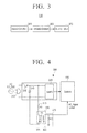
FIG. 3 is a block diagram illustrating a sensor according to exemplary embodiments of the present general inventive concept; -
FIG. 4 illustrates a circuit diagram of the sensor ofFIG. 3 ; -
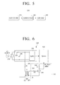
FIG. 5 is a block diagram illustrating a sensor according to exemplary embodiments of the present general inventive concept; -
FIG. 6 illustrates a circuit diagram of the sensor ofFIG. 5 ; -
FIG. 7 is a block diagram illustrating a sensor according to exemplary embodiments of the present general inventive concept; -
FIG. 8 illustrates a circuit diagram of the sensor ofFIG. 7 ; and -
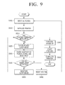
FIG. 9 is a flowchart illustrating an image forming method according to exemplary embodiments of the present general inventive concept. - Reference will now be made in detail to the embodiments of the present general inventive concept, examples of which are illustrated in the accompanying drawings, wherein like reference numerals refer to like elements throughout. The embodiments are described below in order to explain the present general inventive concept by referring to the figures.
-
FIG. 1 is a block diagram illustrating animage forming apparatus 100 according to exemplary embodiments of the present general inventive concept. - Referring to
FIG. 1 , theimage forming apparatus 100 includes acommunication interface unit 110, auser interface unit 120, astorage unit 130, animage forming unit 140, acontroller 150, and apower supply unit 200. Theimage forming apparatus 100 according to exemplary embodiments of the present general inventive concept may be a printer, a copier, a fax machine, or a multifunction peripheral (MFP) having combined functions thereof. - The
communication interface unit 110 is formed to connect theimage forming apparatus 100 to a printcontrol terminal apparatus 50. Thecommunication interface unit 110 may communicatively couple the image forming apparatus to the printcontrol terminal apparatus 50 via a wireless and/or wired communications link. The printcontrol terminal apparatus 50 may be a personal computer, a server, a tablet computer, a personal digital assistant, a cellular phone, a portable media player, and/or any suitable controller to control printing operations and/or provide job data (i.e., print job data, fax job data, etc.) to theimage forming apparatus 100. Thecommunication interface unit 110 of theimage forming apparatus 100 may be connected to the printcontrol terminal apparatus 50 through a local area network (LAN) and the Internet or through a universal serial bus (USB) port, or a wireless communication method such as Global System/Standard for Mobile Communication (GMS), Universal Mobile Telephone System (UMTS), Long Term Evolution (LTE), or the like. - The
communication interface unit 110 receives job data (e.g., printing data, fax transmission data) from the printcontrol terminal apparatus 50 and transmits job data (e.g., scan data, fax reception data) generated by theimage forming apparatus 100 to the printcontrol terminal apparatus 50. Here, the printing data may be data of a printer language such as a postscript (PS), a printer control language (PCL), or the like. If theimage forming apparatus 100 supports direct printing, the printing data may be a file such as PDF, XPS, BMP, JPG, or the like. That is, when theimage forming apparatus 100 supports direct printing, printing data files may be received and printed by theimage forming apparatus 100 without printing though an application. - The
user interface unit 120 includes a plurality of function keys through which a user sets or selects one or more functions supported by theimage forming apparatus 100 and displays one or more types of information provided from theimage forming apparatus 100. Theuser interface unit 120 may be realized as a unit which simultaneously realizes an input and an output like a touch pad or as a unit into which a plurality of buttons and a monitor are combined. - The
storage unit 130 stores printing data. In detail, thestorage unit 130 stores the printing data received from thecommunication interface unit 110. Thestorage unit 130 may be realized as a storage medium installed in theimage forming apparatus 100, an external storage medium, a removable disk including a USB memory, a web server through a network, or the like. The storage medium of thestorage unit 130 may be a hard disk drive, a solid state drive, a memory device, and/or any suitable storage device to carry out the exemplary embodiments of the present general inventive concept disclosed herein. - The
storage unit 130 can back up and store system data. In detail, if it is sensed that alternating current (AC) power has not been input, thestorage unit 130 backs up and stores system data of theimage forming apparatus 100. Here, the system data is data of job log information, state information, etc. which is to be backed up when theimage forming apparatus 100 is turned off. - The
image forming unit 140 outputs the printing data. In detail, theimage forming unit 140 performs a printing job with respect to the printing data received through thecommunication interface unit 110 or printing data pre-stored in thestorage unit 130. That is, theimage forming unit 140 may output the printing data onto a printing medium that is received from thecommunication interface unit 110 or thestorage unit 130. In exemplary embodiments of the present general inventive concept, theimage forming apparatus 100 includes only theimage forming unit 140 which performs the printing job. In other exemplary embodiments, theimage forming apparatus 100 can support a fax function such as a fax transmission, a fax reception, etc., with a fax processor included in the image forming apparatus to perform the fax function. In exemplary embodiments of the present general inventive concept, theimage forming apparatus 100 can support a scan function, and may include a scanner and/or a scan processor to perform the scan function. That is, the scanner and/or scan processor of the image forming apparatus may scan one or more documents, and may output the scanned documents as print data and/or scan data. The print data and/or scan data may be stored in thestorage unit 130 and/or outputted by the image forming unit 140 (e.g., to a printing medium). - The
controller 150 controls elements of the image forming apparatus 100 (e.g., thecommunication interface unit 110, theuser interface unit 120, the storage unit theimage forming unit 140, etc.). Thecontroller 150 may be a processor, a field programmable gate array, a programmable logic device, an integrated circuit, and/or any suitable controller to carry out the exemplary embodiments of the present general inventive concept. In detail, if the printing job is received through thecommunication interface unit 110, thecontroller 150 controls theimage forming unit 140 to perform the printing job. - The
controller 150 determines whether AC power has been input, by using a sensing signal (e.g., a sensing signal received from the power supply unit 200). In detail, if a phase of the sensing signal is not changed for a preset period (e.g., about 20 ms), thecontroller 150 determines that the AC power has not been input. That is, thecontroller 150 determines that the AC power has not been input to thepower supply unit 200. If the phase of the sensing signal is changed within the preset period, thecontroller 150 determines that the AC power has been input. That is, thecontroller 150 determines that the AC power has been input to thepower supply unit 200. In exemplary embodiments of the present general inventive concept, thecontroller 150 determines whether the AC power has been input, by using the sensing signal received from thepower supply unit 200. In other exemplary embodiments, instead of thecontroller 150, an additional element (e.g., a sensor, a processor, etc.) may determine whether the AC power has been input (e.g., input to the power supply unit 200), by using the sensing signal received from thepower supply unit 200 and transmit the determination result to thecontroller 150. - If it is determined that the AC power has not been input to the
power supply 200, thecontroller 150 cancels the printing job of the received printing data, backs the system data up in thestorage unit 130, and resets a system (e.g., resets thecontroller 150 and/or the image forming apparatus 100). - The
controller 150 determines an operation mode of theimage forming apparatus 100. In detail, thecontroller 150 determines whether the printing job has been performed and determines a time elapsed after the printing job performed, etc. to determine whether the operation mode of theimage forming apparatus 100 is set to a sleep mode (which may also be referred to as a standby mode) or a normal mode. Here, the sleep mode (or standby mode) refers to an operation mode which is to cut off or minimize a supply of power of one or more modules (e.g., cut off or minimize the power to thecommunication interface unit 110, theuser interface unit 120, theimage forming unit 140, etc.) in order to minimize power consumed when any job is not performed. That is, thecontroller 150 may change the operation mode of theimage forming apparatus 100 to a sleep mode after a predetermined period of time after the last printing job has been performed. The normal mode may refer to an operation mode where power is supplied to the elements (e.g., thecommunication interface unit 110, theuser interface unit 120, the storage unit theimage forming unit 140, etc.) of theimage forming apparatus 100 to perform a job (e.g., a printing job). - The
controller 150 controls the elements of the image forming apparatus 100 (e.g., thecommunication interface unit 110, theuser interface unit 120, the storage unit theimage forming unit 140, etc.) to have an operation state corresponding to the determined operation mode. For example, if the operation mode of theimage forming apparatus 100 is determined as the sleep mode, thecontroller 150 controls the elements of theimage forming apparatus 100 to operate only thecommunication interface unit 110 and thecontroller 150. - The
power supply unit 200 supplies power to the elements of the image forming apparatus 100 (e.g., thecommunication interface unit 110, theuser interface unit 120, the storage unit theimage forming unit 140, etc.) and outputs whether the AC power has been input as the sensing signal. That is, the sensing signal output by thepower supply unit 200 includes information as to whether the AC power has been input to thepower supply unit 200. In detail, thepower supply unit 200 receives the AC power from an external source, converts the AC power to direct current (DC) power having a preset level, and outputs the DC power (e.g., as Vout illustrated inFIG. 2 ). In exemplary embodiments of the present general inventive concept, only one DC power is output. In other exemplary embodiments of the present general inventive concept, if theimage forming apparatus 100 uses a plurality of DC powers having different levels, thepower supply unit 200 may output the plurality of DC powers having the different levels. - The
power supply unit 200 outputs whether the AC power has been input as the sensing signal. In detail, thepower supply unit 200 provides the sensing signal, which is electrically insulated from the AC power, to thecontroller 150 by using a sensing circuit (e.g.,sensor 300 illustrated inFIG. 2 ) which operates at a power consumption that is below a predetermined level (e.g. a low power consumption). The detailed structure and operation of thepower supply unit 200 will be described later with reference toFIG. 2 . - As described above, the
image forming apparatus 100 according to the exemplary embodiments of the present general inventive concept senses whether the AC power has been input. Therefore, even if a user unplugs an AC power cord and then plugs the AC power cord in to stop the printing job, theimage forming apparatus 100 may perform an operation corresponding to an intension of the user. That is, the image forming apparatus may stop the printing job if the user unplugs the AC power cord with the intent of stopping the printing job and preventing the wasting of printing medium. Theimage forming apparatus 100 can use a circuit to sense whether power has been supplied, through low power consumption. Therefore, power consumption of, for example, 1W in a standby mode (i.e., sleep mode) can be achieved with the exemplary embodiments of the present general inventive concept. - As described with reference to
FIG. 1 , thepower supply unit 200 is included in theimage forming apparatus 100. However, thepower supply unit 200 may be installed separately from theimage forming apparatus 100. In this case, thepower supply unit 200 may be applied to any electronic device to sense whether power has been supplied. - As described with reference to
FIG. 1 , thepower supply unit 200 can output a plurality of powers (e.g., output different power and/or voltage levels) and can sense whether AC power has been input. However, a function of outputting a plurality of powers and a function of sensing whether AC power has been input may be respectively performed by other elements. That is, there may be a power supply to provide one or more powers to an electronic device (e.g., the image forming apparatus 100), and a separate sensor to sense whether AC power has been input to the separate power supply. -
FIG. 2 is a block diagram illustrating a structure of thepower supply device 200 according to exemplary embodiments of the present general inventive concept. - Referring to
FIG. 2 , thepower supply device 200 includes aninput unit 210, aconverter 220, and asensor 300. Here, thepower supply device 200 may be installed in a particular electronic device (e.g., the image forming apparatus 100) and may be realized as an adaptor type (e.g., a separate external device which is coupled to theimage forming apparatus 100 or another electronic device). - The
input unit 210 receives AC power from an AC source. In detail, theinput unit 210 receives general commercial AC power (e.g., 230V, 50Hz; 120V, 60 Hz). - The
converter 220 converts the AC power to DC power having at least one preset level and outputs the DC power having at least one preset level. In detail, theconverter 220 may be a switching mode power supply (SMPS), convert input AC power to DC power having a preset level (e.g., 24V or 5V), and output the DC power. In exemplary embodiments of the present general inventive concept, theconverter 220 outputs only one DC power. However, theconverter 220 may output a plurality of DC powers having different levels. Theconverter 220 may also include a rectifier circuit or a transformer. - The
sensor 300 is connected to theinput unit 210 in parallel and senses whether the AC power has been input to thepower supply unit 200. Thesensor 300 also outputs whether the AC power has been input, as a sensing signal (e.g., to thecontroller 150 of the image forming apparatus 100). The detailed structure and operation of thesensor 300 will be described later with reference toFIGS. 3 through 8 . - The
power supply device 200 may further include afuse 230 and avaristor 240 as illustrated inFIGS. 4 ,6 , and8 . - The
fuse 230 is connected in series between theinput unit 210 and theconverter 220 and to minimize and/or prevent an overcurrent from flowing in theconverter 220 and thesensor 300 of thepower supply device 200. - The
varistor 240 is connected to theinput unit 210 in parallel and minimizes and/or prevents an excessive surge voltage from flowing in theconverter 220 and thesensor 300 of thepower supply device 200. - As described above, the
power supply device 200 according to the exemplary embodiments of the present general inventive concept includes thesensor 300 and thus senses whether AC power has been input. Thepower supply device 200 uses a sensing circuit to sense whether AC power has been input, through a power consumption that is below a predetermined level (e.g., a low power consumption), and thus has power consumption of, for example, 1W in a standby mode (i.e., a sleep mode). -
FIG. 3 is a block diagram illustrating asensor 300 according to exemplary embodiments of the present general inventive concept.FIG. 4 illustrates a circuit diagram of thesensor 300 ofFIG. 3 . - Referring to
FIGS. 3 and 4 , thesensor 300 according to the exemplary embodiments of the present general inventive concept includes aresistor unit 310, atransformer 320, and anoutput unit 330. - The
resistor unit 310 is connected to thetransformer 320 in series. In detail, theresistor unit 310 includes an end which is connected to an end of theinput unit 210 so that a current of AC power input into thetransformer 320 is lower than or equal to a preset current, and another end which is connected to an end of afirst coil 321 of thetransformer 320. Here, theresistor unit 310 may have a resistance value between 0.2 MΩ and 20 MΩ. If the resistance value of theresistor unit 310 is 2 MΩ, a current flowing in thefirst coil 321 of thetransformer 320 is about 0.1µA. As described above, thepower supply device 200 allows a current below a predetermined level (e.g., a low current) to flow in the first coil of thetransformer 320 by using a resistance above a predetermined level (e.g., a high resistance) in order to minimize power consumed in theresistor unit 310 and thetransformer 320. This resistance value is an example and thus may be changed within a range to minimize a level of the current flowing in thefirst coil 321 of thetransformer 320 so that asecond coil 322 of thetransformer 320 has a voltage between, for example, 1Vpp and 5VPP. - Although the
resistor unit 310 illustrated inFIG. 4 includes only one resistor R1, a plurality of resistors may be connected to one another in theresistor unit 310. - As illustrated in
FIG. 4 , theresistor unit 310 is connected to an end of thefirst coil 321 of thetransformer 320. However, theresistor unit 310 may be connected only to another end of thefirst coil 321 of thetransformer 320 or resistors may be respectively connected to both ends of thefirst coil 321. - The
transformer 320 receives the AC power and outputs a sensing signal having a level reduced compared to a level of the AC power. In detail, thetransformer 320 includes thefirst coil 321 and thesecond coil 322. Here, an end of thefirst coil 321 is connected to theresistor unit 310, and another end of thefirst coil 321 is connected to theinput unit 210. An end of thesecond coil 322 outputs a sensing signal (e.g., AC_Signal Detect illustrated inFIG. 4 ), and another end of thesecond coil 322 is grounded. Here, the number of turns of thefirst coil 321 is larger than the number of turns of thesecond coil 322 in order to output the sensing signal having the level reduced compared to the level of the AC power. For example, a ratio between the numbers of turns of the first andsecond coils second coil 322 of thetransformer 320 has a voltage between about 1 Vpp and about 5 Vpp. Since thetransformer 320 is used as described above, the output sensing signal is a signal which is electrically insulated from the AC power. - The
output unit 330 outputs the sensing signal. In detail, theoutput unit 330 may include a second resistor R2 as illustrated inFIG. 4 . Here, the second resistor R2 includes an end which is commonly connected to the end of thesecond coil 322 of thetransformer 320 and thecontroller 150, and another end which is commonly connected to the other end of thesecond coil 322 of thetransformer 320 and the ground. Therefore, the sensing signal output from theoutput unit 330 is a signal which is electrically insulated from the AC power and has the same frequency as an AC frequency of the AC power if the AC power is being input. - Although
FIG. 4 illustrates that theoutput unit 330 may include only one resistor R2, a plurality of resistors may be connected to one another in series and/or in parallel in theoutput unit 330. - As described above, the
sensor 300 according to exemplary embodiments of the present general inventive concept senses whether power has been supplied, at a power level below a predetermined level of consumption (e.g., low power consumption (about 0.226W)) by using a resistor unit and a transformer. That is, the amount of power used to sense whether power has been supplied can be determined using the power level that is below the predetermined level of consumption. - In exemplary embodiments of the present general inventive concept, a voltage value of the end of the
second coil 322 of thetransformer 320 is output as the sensing signal. However, the sensing signal may be converted and then provided to thecontroller 150 so that thecontroller 150 can detect the sensing signal. This example will now be described with reference toFIGS. 5 through 8 . -
FIG. 5 is a block diagram illustrating a structure of a sensor 300' according to exemplary embodiments of the present general inventive concept.FIG. 6 is a circuit diagram of the sensor 300' ofFIG. 5 . - Referring to
FIGS. 5 and 6 , the sensor 300' according to exemplary embodiments of the present general inventive concept includes aresistor unit 310, atransformer 320, and anamplifier 340. Operations and structures of theresistor unit 310 and thetransformer 320 are as described with reference toFIGS. 3 and 4 , and thus their repeated descriptions will be omitted herein. - The
amplifier 340 amplifies and outputs an output sensing signal. In detail, theamplifier 340 is disposed between thetransformer 320 and thecontroller 150, and amplifies and outputs the sensing signal (e.g., AC_Signal Detect) output from thetransformer 320. For example, as illustrated inFIG. 6 , theamplifier 340 may include two resistors R3 and R4 (e.g., athird resistor 341 and afourth resistor 342, respectively) and one transistor T2 (e.g., transistor 343). - The
third resistor 341 includes an end which is connected to an end of a second coil of thetransformer 320 and another end which is connected to a base of thetransistor 343. - The
fourth resistor 342 includes an end which is connected to a system voltage Vcc and another end which is connected to a collector of thetransistor 343. - The
transistor 343 includes the collector which is connected to the other end of thefourth resistor 342, a base which is connected to thethird resistor 341, and an emitter is commonly connected to the other end of thesecond coil 322 of thetransformer 320 and a ground. In this case, the collector of thetransistor 343 outputs the amplified sensing signal, and a phase of the amplified sensing signal is 180° reversed with a phase of an external AC signal. - In exemplary embodiments of the present general inventive concept, the
amplifier 340 may include a bipolar junction transistor (BJT). However, theamplifier 340 may include a metal-oxide semiconductor field effect transistor (MOSFET) and a comparator, or may be a signal amplifier element. -
FIG. 7 illustrates asensor 300" according to exemplary embodiments of the present general inventive concept.FIG. 8 illustrates a circuit diagram of thesensor 300" ofFIG. 7 . - Referring to
FIGS. 7 and 8 , thesensor 300" according to the exemplary embodiments of the present general inventive concept includes aresistor unit 310, atransformer 320, afirst amplifier 350, afilter 360, and asecond amplifier 370. Operations and structures of theresistor unit 310 and thetransformer 320 are the same as those of theresistor unit 310 and thetransformer 320 ofFIGS. 3 and 4 except that another end of thesecond coil 322 of thetransformer 320 is not grounded, and thus their repeated descriptions will be omitted herein. - The
first amplifier 350 amplifies and outputs an output sensing signal. In detail, thefirst amplifier 350 is disposed between thetransformer 320 and thefilter 360, and firstly amplifies and outputs the sensing signal output from thetransformer 320. For example, as illustrated inFIG. 8 , thefirst amplifier 350 includes four resistors R5, R6, R7, and R8 (e.g., afifth resistor 351, asixth resistor 352, aseventh resistor 353, and an eighth resistor 354) and an operational amplifier (OP-AMP) OP1 (e.g., operational amplifier 355). - The
fifth resistor 351 includes an end which is connected to an end of thesecond coil 322 of thetransformer 320 and another end which is commonly connected to a negative input terminal of an OP-AMP 355 and an end of theeighth resistor 354. - The
sixth resistor 352 includes an end which is connected to the other end of thesecond coil 322 of thetransformer 320 and another end which is commonly connected to a positive input terminal of the OP-AMP 355 and an end of theseventh resistor 353. - The
seventh resistor 353 includes the end which is commonly connected to the other end of thesixth resistor 352 and the positive input terminal of the OP-AMP 355, and another end which is grounded. - The
eighth resistor 354 includes an end which is commonly connected to the other end of thefifth resistor 351 and the negative input terminal of the OP-AMP 355, and another end which is commonly connected to an output terminal of the OP-AMP 355 and thefilter 360. - The OP-
AMP 355 includes the negative input terminal which is commonly connected to the other end of thefifth resistor 351 and the end of theeighth resistor 354, the positive input terminal which is commonly connected to the other end of thesixth resistor 352 and the end of theseventh resistor 353, and the output terminal which is commonly connected to the other end of theeighth resistor 354 and thefilter 360. - The
filter 360 filters the amplified sensing signal. In detail, thefilter 360 is disposed between the first andsecond amplifiers first amplifier 350. For example, as illustrated inFIG. 8 , thefilter 360 may be a high-pass filter (HPF) which includes a resistor R9 (e.g., ninth resistor 362) and a capacitor C1 (e.g., capacitor 361). - The capacitor 361 includes an end which is connected to the
first amplifier 350 and another end which is commonly connected to an end of aninth resistor 362 and thesecond amplifier 370. - The
ninth resistor 362 includes an end which is commonly connected to the other end of the capacitor 361 and thesecond amplifier 370, and another end which is grounded. - As described above, the
filter 360 performs high-pass filtering with respect to the amplified sensing signal and thus removes a DC component from the sensing signal amplified by thefirst amplifier 350. In other words, only an AC component of the amplified sensing signal is accurately transmitted. - In the exemplary embodiments of the present general inventive concept, the
filter 360 may be a HPF. However, thefilter 360 may include a low-pass filter (LPF) in order to remove noise occurring in amplification. That is, the sensing signal can be filtered with the LPF to remove noise from the sensing signal before it is amplified by thesecond amplifier 370 and transmitted to thecontroller 150. - The
second amplifier 370 secondarily amplifies and outputs the filtered sensing signal. - In detail, the
second amplifier 370 is disposed between thefilter 360 and thecontroller 150, and secondarily amplifies and outputs the sensing signal filtered by thefilter 360. For example, as illustrated inFIG. 8 , thesecond amplifier 370 includes three resistors R10, R11, and R12 and an OP-AMP OP2 (e.g., OP-AMP 374). - A
tenth resistor 371 includes an end which is connected to thefilter 360 and another end which is commonly connected to a negative input terminal of an OP-AMP 374 and an end of aeleventh resistor 372. - The
eleventh resistor 372 includes an end which is commonly connected to the other end of thetenth resistor 371 and the negative input terminal of the OP-AMP 374, and another end which is commonly connected to an end of a twelfth resistor 373, an output terminal of the OP-AMP 374, and thecontroller 150. - The twelfth resistor 373 includes the end which is commonly connected to the other end of the
eleventh resistor 372, the output terminal of the OP-AMP 374, and thecontroller 150, and another end which is grounded. - The OP-
AMP 374 includes the negative input terminal which is commonly connected to the other end of thetenth resistor 371 and the end of theeleventh resistor 372, a positive input terminal which is connected to a ground, and the output terminal which is commonly connected to the other end of theeleventh resistor 372, the end of the twelfth resistor 373, and thecontroller 150. - As described with reference to
FIGS. 7 and 8 , only thefirst amplifier 350, thefilter 360, and thesecond amplifier 370 are used. However, only thefirst amplifier 350 and thefilter 360 may be used along with theresistor unit 310 and thetransformer 320, only thefilter 360 and thesecond amplifier 370 may be used along with theresistor unit 310 and thetransformer 320, or only the first andsecond amplifiers resistor unit 310 and thetransformer 320. -
FIG. 9 is a flowchart illustrating an image forming method according to exemplary embodiments of the present general inventive concept. - In operation S905, AC power is input. In operation S910, an image forming apparatus (e.g.,
image forming apparatus 100 illustrated inFIG. 1 ) is reset. - In operation S915, a determination is made as to whether printing data has been input. That is, a determination is made as to whether printing data is received from the print
control terminal apparatus 50 ofFIG. 1 , from theimage forming unit 140, and/or thestorage unit 130. If it is determined in operation S915 that the printing data has not been input and a preset time has elapsed after a printing job is performed, an operation mode of the image forming apparatus is changed to a sleep mode in operation S920. In exemplary embodiments of the present general inventive concept, the operation mode of the image forming apparatus can be changed to the sleep mode from a normal mode. - In operation S930, whether AC power has been input is sensed. That is, operation S930 determined if an AC signal has been detected. If it is sensed in operation S930 that the AC power has been input, a current operation mode (i.e., the sleep mode) is maintained in operation S935. In exemplary embodiments of the present general inventive concept, whether AC power has been input is sensed only in a sleep mode. In other exemplary embodiments of the present general inventive concept, a determination as to whether AC power has been input or has been cut off may be made in a normal mode.
- If it is sensed in operation S930 that the AC power has not been input, i.e., supply of the AC power has been cut off, a system (e.g.,
controller 150 of the image forming apparatus 100) of the image forming apparatus is reset in operation S940. In detail, if the printing data is received, the printing job may be cancelled, system data may be backed up in thestorage unit 130, and the system (e.g.,controller 150 of the image forming apparatus 100) may be reset. - If the printing data is input in operation S915, the current operation mode (e.g., the sleep mode and/or a standby mode) is changed to the normal mode, and a warm-up is performed to perform the printing job in operation S945. If the warm-up is completed, the printing job is performed with respect to the printing data in operations S950 and 955.
- As described above, embodiments of the invention provide a power supply device, comprising: an input unit arranged to input alternating current (AC) power; a converter arranged to convert the input AC power to direct current (DC) power having a preset level and to output the DC power; and a sensor arranged to be connected to the input unit and to sense whether the AC power has been input, the sensor including: a transformer arranged to receive the AC power and to output a sensing signal having a level reduced compared to a level of the AC power; and a resistor unit connected to the transformer in series so that a current of the AC power input into the transformer is lower than or equal to a preset current.
- Embodiments of the invention can also provide an image forming device including such a power supply device.
- As described above, in the image forming method according to exemplary embodiments of the present general inventive concept, it is sensed whether AC power has been input. Therefore, even if a user unplugs an AC power cord and then plugs the AC power cord in to stop a printing job, an operation corresponding to an command and/or selection from the user may be performed. The image forming method of
FIG. 9 may be performed by an image forming apparatus having, for example, the structure ofFIG. 1 or image forming apparatuses having other types of structures. - Although various example embodiments of the present general inventive concept have been illustrated and described, it will be appreciated by those skilled in the art that changes may be made in these example embodiments without departing from the principles t of the general inventive concept, the scope of which is defined in the appended claims.
Claims (15)
- A power supply device, comprising:an input unit arranged to input alternating current (AC) power;a converter arranged to convert the input AC power to direct current (DC) power having a preset level and to output the DC power; anda sensor arranged to be connected to the input unit in parallel and to sense whether the AC power has been input, the sensor including:a transformer arranged to receive the AC power and to output a sensing signal having a level reduced compared to a level of the AC power; anda resistor unit connected to the transformer in series so that a current of the AC power input into the transformer is lower than or equal to a preset current.
- The power supply device of claim 1, wherein the sensing signal is a signal which is electrically insulated from the AC power.
- The power supply device of claim 1 or 2, wherein the transformer comprises:a first coil comprising an end which is connected to the resistor unit and an other end which is connected to the input unit; anda second coil comprising an end which outputs the sensing signal and an other end which is grounded.
- The power supply device of claim 3, wherein the number of turns of the first coil is larger than the number of turns of the second coil.
- The power supply device of claim 3, wherein a ratio between the turns of the first and second coils is 300:1.
- The power supply device of claim 3, wherein the resistor unit has a resistance value between 0.2 MΩ, and 20 MΩ.
- The power supply device of any one of claims 1 through 6, wherein if the AC power is input, the sensing signal has the same frequency as an AC frequency of the AC power.
- The power supply device of any one of claims 1 through 7, further comprising:an amplifier arranged to amplify and output the output sensing signal.
- The power supply device of claim 8, wherein the amplifier is arranged to amplify the sensing signal by using at least one of a transistor and an operational amplifier (OP-AMP).
- The power supply device of any one of claims 1 through 9, further comprising:a filter arranged to filter the output sensing signal; andan amplifier arranged to amplify and output the filtered sensing signal.
- The power supply device of any one of claims 1 through 9, further comprising:a first amplifier arranged to firstly amplify and output the output sensing signal;a filter arranged to filter the amplified sensing signal; anda second amplifier arranged to secondarily amplify and output the filtered sensing signal.
- The power supply device of claim 11, wherein the first amplifier is a comparator which uses an operational amplifier (OP-AMP).
- The power supply device of claim 11 or 12, wherein the filter is at least one of a low-pass filter (LPF) and a high-pass filter (HPF).
- The power supply device of any one of claims 1 through 13, further comprising:a varistor arranged to be connected to the input unit in parallel.
- An image forming apparatus comprising:a power supply unit to supply power to the image forming apparatus and to output a sensing signal as to whether AC power has been input to the power supply unit, the power supply unit including:a transformer to receive the AC power and to output the sensing signal having a level reduced more than a level of the AC power; anda resistor unit to be connected to the transformer in series so that a current of the AC power input into the transformer is lower than or equal to a preset current;a communication interface unit to receive printing data;an image forming unit to print the received printing data; anda controller to determine whether the AC power has been input, by using the sensing signal and, if it is determined that the AC power has not been input, to cancel a printing job of the received printing data.
Applications Claiming Priority (1)
| Application Number | Priority Date | Filing Date | Title |
|---|---|---|---|
| KR1020120052020A KR20130128168A (en) | 2012-05-16 | 2012-05-16 | Power supply device and image forming apparatus having the same |
Publications (2)
| Publication Number | Publication Date |
|---|---|
| EP2664930A2 true EP2664930A2 (en) | 2013-11-20 |
| EP2664930A3 EP2664930A3 (en) | 2018-01-03 |
Family
ID=47747366
Family Applications (1)
| Application Number | Title | Priority Date | Filing Date |
|---|---|---|---|
| EP13153411.7A Withdrawn EP2664930A3 (en) | 2012-05-16 | 2013-01-31 | Power supply device and image forming apparatus having the same |
Country Status (8)
| Country | Link |
|---|---|
| US (1) | US9075546B2 (en) |
| EP (1) | EP2664930A3 (en) |
| JP (1) | JP2013240270A (en) |
| KR (1) | KR20130128168A (en) |
| CN (1) | CN103419512B (en) |
| AU (1) | AU2013200284B2 (en) |
| BR (1) | BR102013003574A2 (en) |
| RU (1) | RU2612651C2 (en) |
Families Citing this family (4)
| Publication number | Priority date | Publication date | Assignee | Title |
|---|---|---|---|---|
| CN104914969A (en) * | 2014-03-13 | 2015-09-16 | 鸿富锦精密工业(武汉)有限公司 | Connector port power supply circuit |
| US9833991B2 (en) * | 2014-09-29 | 2017-12-05 | Funai Electric Co., Ltd. | Printhead and an inkjet printer |
| KR102490226B1 (en) * | 2015-12-17 | 2023-01-20 | 삼성디스플레이 주식회사 | Transparent display device and electronic device having the same |
| JP6926890B2 (en) * | 2017-09-25 | 2021-08-25 | コニカミノルタ株式会社 | AC input detection device and image processing device |
Citations (3)
| Publication number | Priority date | Publication date | Assignee | Title |
|---|---|---|---|---|
| US4928055A (en) * | 1988-11-25 | 1990-05-22 | Kentek Information Systems, Inc. | Control circuit for heat fixing device for use in an image forming apparatus |
| EP0665629A2 (en) * | 1994-01-28 | 1995-08-02 | Canon Kabushiki Kaisha | Power control device and image forming apparatus utilizing the same |
| US20040022550A1 (en) * | 2002-06-19 | 2004-02-05 | Norikazu Okada | Method of and apparatus for deriving information, electric appliance, image formation apparatus, and computer product |
Family Cites Families (19)
| Publication number | Priority date | Publication date | Assignee | Title |
|---|---|---|---|---|
| GB1504054A (en) * | 1975-05-31 | 1978-03-15 | Searle T | Electrical isolaters |
| EP0280100B1 (en) | 1987-02-10 | 1995-05-10 | Matsushita Electric Industrial Co., Ltd. | High-frequency heating apparatus |
| JPH06350761A (en) * | 1993-06-11 | 1994-12-22 | Konica Corp | Facsimile equipment |
| JPH07325114A (en) * | 1994-05-31 | 1995-12-12 | Okuma Mach Works Ltd | Voltage detection circuit |
| KR0120474Y1 (en) | 1995-08-31 | 1998-07-15 | 배순훈 | Power plug open warning device for TV |
| JPH11191483A (en) | 1997-12-25 | 1999-07-13 | Canon Inc | Power supply |
| JP2001166645A (en) * | 1999-12-09 | 2001-06-22 | Konica Corp | Image forming device |
| US6988222B2 (en) * | 2002-12-03 | 2006-01-17 | Uniloy Milacron U.S.A. Inc. | Power failure detection and response |
| JP4231348B2 (en) * | 2003-06-27 | 2009-02-25 | 株式会社東芝 | Image forming apparatus and image forming system |
| JP2005062334A (en) * | 2003-08-08 | 2005-03-10 | Ricoh Co Ltd | Image forming apparatus |
| EP1610134B1 (en) * | 2004-06-25 | 2006-03-29 | Alcatel | Controlled inverter for LED signalling device |
| CN2891431Y (en) * | 2006-04-10 | 2007-04-18 | 苏州市华芯微电子有限公司 | Instantaneous AC outage protective circuit |
| US7733251B2 (en) * | 2007-09-13 | 2010-06-08 | Ricoh Company, Limited | A/D convertion controlling device and image forming apparatus |
| WO2009125532A1 (en) * | 2008-04-11 | 2009-10-15 | シャープ株式会社 | Active matrix substrate and liquid crystal display device |
| US7928722B2 (en) * | 2009-02-20 | 2011-04-19 | Square D Company | Apparatus and method for voltage sensing in electrical metering systems |
| JP4965619B2 (en) * | 2009-09-16 | 2012-07-04 | 東芝テック株式会社 | Printer, program, and printing start position determination method |
| JP2012022093A (en) * | 2010-07-13 | 2012-02-02 | Ricoh Co Ltd | Image forming apparatus, fixing device and fixing control method |
| JP5843433B2 (en) * | 2010-09-30 | 2016-01-13 | キヤノン株式会社 | Power supply device and image forming apparatus |
| US8335096B2 (en) * | 2010-11-12 | 2012-12-18 | Don Roy Sauer | Rectifier less bidirectional AC to DC converter |
-
2012
- 2012-05-16 KR KR1020120052020A patent/KR20130128168A/en not_active Ceased
- 2012-11-26 US US13/684,900 patent/US9075546B2/en active Active
-
2013
- 2013-01-16 AU AU2013200284A patent/AU2013200284B2/en not_active Ceased
- 2013-01-31 EP EP13153411.7A patent/EP2664930A3/en not_active Withdrawn
- 2013-02-15 RU RU2013106905A patent/RU2612651C2/en not_active IP Right Cessation
- 2013-02-15 BR BRBR102013003574-2A patent/BR102013003574A2/en not_active Application Discontinuation
- 2013-04-01 CN CN201310110223.9A patent/CN103419512B/en active Active
- 2013-05-14 JP JP2013101983A patent/JP2013240270A/en active Pending
Patent Citations (3)
| Publication number | Priority date | Publication date | Assignee | Title |
|---|---|---|---|---|
| US4928055A (en) * | 1988-11-25 | 1990-05-22 | Kentek Information Systems, Inc. | Control circuit for heat fixing device for use in an image forming apparatus |
| EP0665629A2 (en) * | 1994-01-28 | 1995-08-02 | Canon Kabushiki Kaisha | Power control device and image forming apparatus utilizing the same |
| US20040022550A1 (en) * | 2002-06-19 | 2004-02-05 | Norikazu Okada | Method of and apparatus for deriving information, electric appliance, image formation apparatus, and computer product |
Non-Patent Citations (2)
| Title |
|---|
| COILWS.COM: "Current Sense Transformer", 23 May 2004 (2004-05-23), XP055650455, Retrieved from the Internet <URL:http://www.coilws.com/Current%20Sense/CurrentSense_pdf/72-406new.pdf> [retrieved on 20191206] * |
| TALEMA: "Talema AS Series Current Sense Inductors & Transformers", 30 June 2006 (2006-06-30), XP055650481, Retrieved from the Internet <URL:https://html.alldatasheet.com/html-pdf/240953/TALEMA/AS-103/215/1/AS-103.html> [retrieved on 20191206] * |
Also Published As
| Publication number | Publication date |
|---|---|
| CN103419512A (en) | 2013-12-04 |
| RU2612651C2 (en) | 2017-03-13 |
| EP2664930A3 (en) | 2018-01-03 |
| KR20130128168A (en) | 2013-11-26 |
| RU2013106905A (en) | 2014-08-20 |
| JP2013240270A (en) | 2013-11-28 |
| AU2013200284B2 (en) | 2015-04-30 |
| BR102013003574A2 (en) | 2015-06-16 |
| US20130308152A1 (en) | 2013-11-21 |
| US9075546B2 (en) | 2015-07-07 |
| CN103419512B (en) | 2017-07-21 |
Similar Documents
| Publication | Publication Date | Title |
|---|---|---|
| KR101365602B1 (en) | Apparatus for power supplying and image forming apparatus including the same | |
| US9559527B2 (en) | Discharging circuit, image forming apparatus having the discharging circuit, and power supply unit | |
| EP2664930A2 (en) | Power supply device and image forming apparatus having the same | |
| EP2590288A2 (en) | Switching mode power supply including surge protection circuit and image forming apparatus including the same | |
| JP5826158B2 (en) | Power supply device and image forming apparatus provided with the same | |
| US20150256079A1 (en) | Electric power supply control device which can lower power consumption | |
| CN112673319B (en) | Power supply equipment that outputs zero-crossing information of half AC wave | |
| EP2827482A2 (en) | Power control device and image forming apparatus inlcuding the same | |
| JP6205956B2 (en) | Power supply, electronic device and system | |
| CN205489774U (en) | Power supply unit and printer | |
| US11483445B2 (en) | Temperature estimation of DC motor based on sensing voltage | |
| US11513459B2 (en) | Power supply apparatus for selectively changing power amplification method based on power mode of image forming device | |
| US20190214915A1 (en) | Power supply device and image forming apparatus having the same | |
| US8631258B2 (en) | Apparatus and method for controlling power of fixing unit | |
| JP2018183052A (en) | Electronic device, power supply system and non-contact power supply method | |
| EP2529294A1 (en) | Information processing apparatus and control method of information processing apparatus | |
| US20150222190A1 (en) | Power supply device and image forming apparatus having the same | |
| WO2020055531A1 (en) | Temperature estimation of step motor based on sensing voltage thereof | |
| JP6299646B2 (en) | Sensor and image forming apparatus | |
| CN220252398U (en) | Fixing module heating control circuit and image forming device | |
| JP2012217309A (en) | Power-supply device and image formation apparatus | |
| JP2017049672A (en) | Voltage adjusting device and image forming apparatus | |
| JP2017070092A (en) | Electrical machine | |
| JP2010093900A (en) | Power supply control device, and electronic apparatus with the same | |
| JP2007043776A (en) | Switching power supply |
Legal Events
| Date | Code | Title | Description |
|---|---|---|---|
| PUAI | Public reference made under article 153(3) epc to a published international application that has entered the european phase |
Free format text: ORIGINAL CODE: 0009012 |
|
| AK | Designated contracting states |
Kind code of ref document: A2 Designated state(s): AL AT BE BG CH CY CZ DE DK EE ES FI FR GB GR HR HU IE IS IT LI LT LU LV MC MK MT NL NO PL PT RO RS SE SI SK SM TR |
|
| AX | Request for extension of the european patent |
Extension state: BA ME |
|
| RAP1 | Party data changed (applicant data changed or rights of an application transferred) |
Owner name: S-PRINTING SOLUTION CO., LTD. |
|
| PUAL | Search report despatched |
Free format text: ORIGINAL CODE: 0009013 |
|
| RIC1 | Information provided on ipc code assigned before grant |
Ipc: G01R 19/00 20060101ALI20171123BHEP Ipc: G01R 19/15 20060101ALN20171123BHEP Ipc: H02J 9/00 20060101ALI20171123BHEP Ipc: H02M 1/00 20060101AFI20171123BHEP Ipc: G03G 15/00 20060101ALI20171123BHEP Ipc: G06F 3/12 20060101ALN20171123BHEP |
|
| AK | Designated contracting states |
Kind code of ref document: A3 Designated state(s): AL AT BE BG CH CY CZ DE DK EE ES FI FR GB GR HR HU IE IS IT LI LT LU LV MC MK MT NL NO PL PT RO RS SE SI SK SM TR |
|
| AX | Request for extension of the european patent |
Extension state: BA ME |
|
| STAA | Information on the status of an ep patent application or granted ep patent |
Free format text: STATUS: REQUEST FOR EXAMINATION WAS MADE |
|
| RAP1 | Party data changed (applicant data changed or rights of an application transferred) |
Owner name: HP PRINTING KOREA CO., LTD. |
|
| 17P | Request for examination filed |
Effective date: 20180522 |
|
| RBV | Designated contracting states (corrected) |
Designated state(s): AL AT BE BG CH CY CZ DE DK EE ES FI FR GB GR HR HU IE IS IT LI LT LU LV MC MK MT NL NO PL PT RO RS SE SI SK SM TR |
|
| STAA | Information on the status of an ep patent application or granted ep patent |
Free format text: STATUS: EXAMINATION IS IN PROGRESS |
|
| 17Q | First examination report despatched |
Effective date: 20180821 |
|
| RAP1 | Party data changed (applicant data changed or rights of an application transferred) |
Owner name: HEWLETT-PACKARD DEVELOPMENT COMPANY, L.P. |
|
| STAA | Information on the status of an ep patent application or granted ep patent |
Free format text: STATUS: THE APPLICATION IS DEEMED TO BE WITHDRAWN |
|
| 18D | Application deemed to be withdrawn |
Effective date: 20200603 |