EP2664855A2 - Cooking appliance and method for same - Google Patents
Cooking appliance and method for same Download PDFInfo
- Publication number
- EP2664855A2 EP2664855A2 EP20130167168 EP13167168A EP2664855A2 EP 2664855 A2 EP2664855 A2 EP 2664855A2 EP 20130167168 EP20130167168 EP 20130167168 EP 13167168 A EP13167168 A EP 13167168A EP 2664855 A2 EP2664855 A2 EP 2664855A2
- Authority
- EP
- European Patent Office
- Prior art keywords
- electricity
- illumination source
- hot surface
- storage device
- state
- Prior art date
- Legal status (The legal status is an assumption and is not a legal conclusion. Google has not performed a legal analysis and makes no representation as to the accuracy of the status listed.)
- Withdrawn
Links
- 238000010411 cooking Methods 0.000 title claims abstract description 22
- 238000000034 method Methods 0.000 title claims abstract description 13
- 238000005286 illumination Methods 0.000 claims abstract description 69
- 230000005611 electricity Effects 0.000 claims description 105
- 239000003990 capacitor Substances 0.000 claims description 7
- 230000003213 activating effect Effects 0.000 claims description 2
- 230000008878 coupling Effects 0.000 claims description 2
- 238000010168 coupling process Methods 0.000 claims description 2
- 238000005859 coupling reaction Methods 0.000 claims description 2
- 238000010586 diagram Methods 0.000 description 2
- 230000000694 effects Effects 0.000 description 1
- 230000005612 types of electricity Effects 0.000 description 1
Images

Classifications
-
- H—ELECTRICITY
- H05—ELECTRIC TECHNIQUES NOT OTHERWISE PROVIDED FOR
- H05B—ELECTRIC HEATING; ELECTRIC LIGHT SOURCES NOT OTHERWISE PROVIDED FOR; CIRCUIT ARRANGEMENTS FOR ELECTRIC LIGHT SOURCES, IN GENERAL
- H05B3/00—Ohmic-resistance heating
- H05B3/68—Heating arrangements specially adapted for cooking plates or analogous hot-plates
- H05B3/74—Non-metallic plates, e.g. vitroceramic, ceramic or glassceramic hobs, also including power or control circuits
- H05B3/746—Protection, e.g. overheat cutoff, hot plate indicator
-
- F—MECHANICAL ENGINEERING; LIGHTING; HEATING; WEAPONS; BLASTING
- F24—HEATING; RANGES; VENTILATING
- F24C—DOMESTIC STOVES OR RANGES ; DETAILS OF DOMESTIC STOVES OR RANGES, OF GENERAL APPLICATION
- F24C15/00—Details
- F24C15/10—Tops, e.g. hot plates; Rings
- F24C15/102—Tops, e.g. hot plates; Rings electrically heated
- F24C15/105—Constructive details concerning the regulation of the temperature
-
- F—MECHANICAL ENGINEERING; LIGHTING; HEATING; WEAPONS; BLASTING
- F24—HEATING; RANGES; VENTILATING
- F24C—DOMESTIC STOVES OR RANGES ; DETAILS OF DOMESTIC STOVES OR RANGES, OF GENERAL APPLICATION
- F24C3/00—Stoves or ranges for gaseous fuels
- F24C3/12—Arrangement or mounting of control or safety devices
- F24C3/126—Arrangement or mounting of control or safety devices on ranges
-
- F—MECHANICAL ENGINEERING; LIGHTING; HEATING; WEAPONS; BLASTING
- F24—HEATING; RANGES; VENTILATING
- F24C—DOMESTIC STOVES OR RANGES ; DETAILS OF DOMESTIC STOVES OR RANGES, OF GENERAL APPLICATION
- F24C7/00—Stoves or ranges heated by electric energy
- F24C7/08—Arrangement or mounting of control or safety devices
- F24C7/082—Arrangement or mounting of control or safety devices on ranges, e.g. control panels, illumination
- F24C7/083—Arrangement or mounting of control or safety devices on ranges, e.g. control panels, illumination on tops, hot plates
-
- F—MECHANICAL ENGINEERING; LIGHTING; HEATING; WEAPONS; BLASTING
- F23—COMBUSTION APPARATUS; COMBUSTION PROCESSES
- F23N—REGULATING OR CONTROLLING COMBUSTION
- F23N2231/00—Fail safe
- F23N2231/02—Fail safe using electric energy accumulators
-
- F—MECHANICAL ENGINEERING; LIGHTING; HEATING; WEAPONS; BLASTING
- F23—COMBUSTION APPARATUS; COMBUSTION PROCESSES
- F23N—REGULATING OR CONTROLLING COMBUSTION
- F23N2231/00—Fail safe
- F23N2231/20—Warning devices
- F23N2231/22—Warning devices using warning lamps
Definitions
- a method of illuminating a Hot Surface Indicator having an illumination source in a cooking appliance having at least one burner activated by a control selector operable between ON and OFF states includes storing electricity in an electricity storage device when the control selector is in the ON state and supplying electricity stored in the electricity storage device to the illumination source of the Hot Surface Indicator while the control selector is in the OFF state.
- a cooking appliance includes at least one burner operable in an ON condition for producing heat and an OFF condition for not producing heat, a Hot Surface Indicator having an illumination source, an electricity storage device electrically coupled to the illumination source of the Hot Surface Indicator, a switch electrically coupling the storage device to an electricity source, and a control selector operable between an ON state for placing the burner in the ON condition and an OFF state for placing the burner in the OFF condition, and activating the switch to electrically couple the electricity source to the electricity storage device when the control selector is in the ON state.
- Figure 1 is a schematic illustration of a cooktop for a cooking appliance according to an embodiment of the invention.
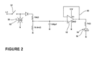
- FIG 2 is a schematic illustration of a control circuit, which may be used in the cooking appliance of Figure 1 according to an embodiment of the invention.
- FIG 1 is a schematic illustration of a cooking appliance 10 having a range or cooktop 12, which may include elements or burners 14 and a set of controls 16 used to control operation of the burners 14 by selecting the temperature settings therefor. While multiple burners 14 have been illustrated, it is contemplated that the cooktop 12 may have any number of burners 14 including a single burner 14. In the illustrated embodiment, the cooktop 12 includes burners 14 in the form of a left rear burner 18, a right rear burner 20, a left front burner 22, and a right front burner 24. The burners 14 may be supplied by electricity or gas.
- the burners 14 may be interconnected to an electricity source or electric power supply 30 schematically illustrated via a switch 32 or the burners 14 may be interconnected to a gas supply line via a regulator and several valves (not shown).
- an electricity source or power supply 30 may be used and may be operably coupled to various elements of the cooking appliance 10 including the switch 32, a user display, a controller, etc.
- the burners 14 may be operable in an ON condition for producing heat and an OFF condition for not producing heat.
- the set of controls 16 may include a control selector for each of the burners 14. More specifically, control selectors 40, 42, 44, and 46, may be operably coupled to the left rear burner 18, right rear burner 20, left front burner 22, and right front burner 24, respectively, to control the operation thereof. Each of the control selectors 40, 42, 44, and 46 may be operable between an ON state for placing the respective burner in the ON condition and an OFF state for placing the respective burner in the OFF condition.
- An On Indicator 50 may be adjacent each of the burners 14.
- the ON Indicators 50 may each include an illumination source 52, which may be used to indicate when each of the burners 14 is in the ON state.
- the illumination sources 52 may each be electrically coupled to the electric power supply 30 by the switch 32.
- the illumination sources 52 may include any suitable type of light or illumination source including an incandescent lamp, a light emitting diode (LED), or an array of several LEDs.
- a Hot Surface indicator 54 may be located on the cooktop 12.
- the Hot Surface indicator 54 may include an illumination source 56, which may be used to indicate that at least one of the burners 14 is hot and should not be touched.
- the illumination source 56 may preferably include an LED or an array of several LEDs.
- An electricity storage device 60 may be included in the cooking appliance 10 and may be electrically coupled to the electric power supply 30 and configured to illuminate the illumination source 56 of the Hot Surface Indicator 54.
- the electricity storage device 60 may be any suitable device capable of storing electricity.
- the electricity storage device 60 may include a capacitor or the electricity storage device 60 may include a resistor-capacitive circuit (RC circuit) and a capacitor may form part of the RC circuit.
- the electricity storage device 60 may subsequently supply the stored electricity to the illumination source 56 of the Hot Surface Indicators 54, either directly or indirectly, while the burners 14 are in the OFF state to illuminate the Hot Surface Indicator 54.
- the electricity storage device 60 may illuminate the illumination source 56 of the Hot Surface Indicator 54 by supplying a control signal to a power source to illuminate the illumination source 56 of the Hot Surface Indicator 54.
- the burners 14 take 5-10 minutes to cool down after the burners 14 are turned off and the electricity storage device 60 may be sized based thereon.
- the electricity storage device 60 may be capable of storing up to 12 V, which may be an amount of electricity for the illumination source 56 of the Hot Surface Indicator 54 to remain illuminated by the stored electricity until the burner 14 is cool enough to touch.
- electricity may be stored in the electricity storage device 60 when one of the control selectors 40, 42, 44, and 46 is in the ON state. Electricity may begin to be stored as soon as any burner 14 is turned on and the appropriate amount of electricity may be stored in the electricity storage device 60 in the time it takes for the burner 14 to heat to a temperature not suitable for touching.
- a timer (not shown) may be included and used to set the time at which the illumination source 56 of the Hot Surface Indicator 54 will come on.
- a timer may include a 555 timer or a 741 op-amp and such time may range from zero to fifteen seconds.
- the illumination source 56 of the Hot Surface Indicator 54 may be configured to come on more quickly than for a burner 14 supplied by electricity as the burner 14 supplied by gas may heat up faster.
- the illumination source 56 of a gas supplied burner 14 may come on between 0-5 seconds while the illumination source 56 of an electrically supplied burner 14 may come on between 5-15 seconds.
- the electricity storage device 60 may include a timing circuit to control the supply of electricity from the electricity storage device 60 to the illumination source 56 of the Hot Surface Indicator 54.
- a timing circuit may signal the illumination source 56 of the Hot Surface Indicator 54 to turn off when electricity storage device 60 falls below a specified voltage. For example, if electricity storage device 60 holds 12 V when fully charged, the timing circuit may be configured to shut of the illumination source 56 of the Hot Surface Indicator 54 when the electricity storage device 60 has depleted to below 7 V.
- a 555 timer or a 741 op-amp may be used to control the supply of electricity to the illumination source 56.
- control circuitry illustrated may be used in the instance where the electricity storage device 60 is not large enough to power the illumination source 56 of the Hot Surface Indicator 54for a long enough time period for the burners to sufficiently cool.
- the stored electricity in the electricity storage device 60 acts as a control signal input to the op-amp 62 and the output of the op-amp 62 in turn powers the illumination source 56 of the Hot Surface Indicator 54.
- the op-amp 62 may act as an amplifier to amplify the stored electricity supplied to the illumination source 56 of the Hot Surface Indicator 54 and a switch that is responsive to the control signal. In this manner, the stored electricity in the electricity storage device 60 controls the supply of electricity from the power source to the illumination source 56 of the Hot Surface Indicator 54 while the control selector is in the off state.
Landscapes
- Engineering & Computer Science (AREA)
- Chemical & Material Sciences (AREA)
- Combustion & Propulsion (AREA)
- Mechanical Engineering (AREA)
- General Engineering & Computer Science (AREA)
- Ceramic Engineering (AREA)
- Baking, Grill, Roasting (AREA)
- Electric Stoves And Ranges (AREA)
- Induction Heating Cooking Devices (AREA)
Abstract
Description
- Contemporary cooking appliances may include separate indicator lights for indicating that the cooktop is ON and another indicating that the cooktop is hot. To illuminate the cooktop hot light, the cooking appliance may include a set of thermally expanding contacts on each individual element and these contacts expand to close when the element is hot, completing the circuit, and open when the element is cool, opening the circuit. Such a method for illuminating the lights may be unreliable as over time the thermal expansion of the contacts may vary and can cause the light to be on for extended periods of time or even permanently. Some contemporary cooking appliances use a separate control board to indicate to the consumer that the cooktop is hot, but these are appliances in which expensive microcontrollers rather than less expensive rotary switches are used.
- According to an embodiment of the invention, a method of illuminating a Hot Surface Indicator having an illumination source in a cooking appliance having at least one burner activated by a control selector operable between ON and OFF states includes storing electricity in an electricity storage device when the control selector is in the ON state and supplying electricity stored in the electricity storage device to the illumination source of the Hot Surface Indicator while the control selector is in the OFF state.
- According to another embodiment of the invention, a cooking appliance includes at least one burner operable in an ON condition for producing heat and an OFF condition for not producing heat, a Hot Surface Indicator having an illumination source, an electricity storage device electrically coupled to the illumination source of the Hot Surface Indicator, a switch electrically coupling the storage device to an electricity source, and a control selector operable between an ON state for placing the burner in the ON condition and an OFF state for placing the burner in the OFF condition, and activating the switch to electrically couple the electricity source to the electricity storage device when the control selector is in the ON state.
- In the drawings:
-
Figure 1 is a schematic illustration of a cooktop for a cooking appliance according to an embodiment of the invention. -
Figure 2 is a schematic illustration of a control circuit, which may be used in the cooking appliance ofFigure 1 according to an embodiment of the invention. -
Figure 1 is a schematic illustration of acooking appliance 10 having a range orcooktop 12, which may include elements orburners 14 and a set ofcontrols 16 used to control operation of theburners 14 by selecting the temperature settings therefor. Whilemultiple burners 14 have been illustrated, it is contemplated that thecooktop 12 may have any number ofburners 14 including asingle burner 14. In the illustrated embodiment, thecooktop 12 includesburners 14 in the form of a leftrear burner 18, a rightrear burner 20, aleft front burner 22, and a rightfront burner 24. Theburners 14 may be supplied by electricity or gas. For example, theburners 14 may be interconnected to an electricity source orelectric power supply 30 schematically illustrated via aswitch 32 or theburners 14 may be interconnected to a gas supply line via a regulator and several valves (not shown). In both the electrically supplied and gas supplied embodiments, an electricity source orpower supply 30 may be used and may be operably coupled to various elements of thecooking appliance 10 including theswitch 32, a user display, a controller, etc. - Regardless of whether the
burner 14 is supplied by a gas supply line or theelectric power supply 30, theburners 14 may be operable in an ON condition for producing heat and an OFF condition for not producing heat. The set ofcontrols 16 may include a control selector for each of theburners 14. More specifically,control selectors rear burner 18, rightrear burner 20, leftfront burner 22, and rightfront burner 24, respectively, to control the operation thereof. Each of thecontrol selectors - An On
Indicator 50 may be adjacent each of theburners 14. TheON Indicators 50 may each include anillumination source 52, which may be used to indicate when each of theburners 14 is in the ON state. Theillumination sources 52 may each be electrically coupled to theelectric power supply 30 by theswitch 32. Theillumination sources 52 may include any suitable type of light or illumination source including an incandescent lamp, a light emitting diode (LED), or an array of several LEDs. - Further, a
Hot Surface indicator 54 may be located on thecooktop 12. TheHot Surface indicator 54 may include anillumination source 56, which may be used to indicate that at least one of theburners 14 is hot and should not be touched. Theillumination source 56 may preferably include an LED or an array of several LEDs. - An
electricity storage device 60 may be included in thecooking appliance 10 and may be electrically coupled to theelectric power supply 30 and configured to illuminate theillumination source 56 of theHot Surface Indicator 54. Theelectricity storage device 60 may be any suitable device capable of storing electricity. For example, theelectricity storage device 60 may include a capacitor or theelectricity storage device 60 may include a resistor-capacitive circuit (RC circuit) and a capacitor may form part of the RC circuit. Theelectricity storage device 60 may subsequently supply the stored electricity to theillumination source 56 of theHot Surface Indicators 54, either directly or indirectly, while theburners 14 are in the OFF state to illuminate theHot Surface Indicator 54. Alternatively, theelectricity storage device 60 may illuminate theillumination source 56 of theHot Surface Indicator 54 by supplying a control signal to a power source to illuminate theillumination source 56 of theHot Surface Indicator 54. - Regardless of the type of
electricity storage device 60, theelectricity storage device 60 may be sized to store an amount of electricity for theillumination source 56 of theHot Surface Indicator 54 to remain illuminated until theburner 14 is cool enough to touch after the respective one of thecontrol selectors electricity storage device 60 may be sized for theillumination source 56 of theHot Surface Indicator 54 to remain illuminated until therespective burner 14 is in the range of 25 °C to 65 °C. Such a size calculation may be calculated based on a highest temperature theburners 14 are capable of reaching. For example, at such a highest temperature it may be known that theburners 14 take 5-10 minutes to cool down after theburners 14 are turned off and theelectricity storage device 60 may be sized based thereon. By way of non-limiting example, it is contemplated that theelectricity storage device 60 may be capable of storing up to 12 V, which may be an amount of electricity for theillumination source 56 of theHot Surface Indicator 54 to remain illuminated by the stored electricity until theburner 14 is cool enough to touch. - The
control selectors switch 32 such that when one of thecontrol selectors switch 32 to electrically couple theelectric power supply 30 to theelectricity storage device 60. In operation, when one of thecontrol selectors switch 32 electrically couples theelectric power supply 30 to theillumination source 52 of the ONIndicator 50 such that electricity is supplied to theillumination source 52. While electricity is being supplied to theillumination source 52 for the ONIndicator 50, electricity may also be supplied to theelectricity storage device 60, where it is stored for subsequent use. Thus, electricity may be stored in theelectricity storage device 60 when one of thecontrol selectors burner 14 is turned on and the appropriate amount of electricity may be stored in theelectricity storage device 60 in the time it takes for theburner 14 to heat to a temperature not suitable for touching. - A timer (not shown) may be included and used to set the time at which the
illumination source 56 of theHot Surface Indicator 54 will come on. For example, such a timer may include a 555 timer or a 741 op-amp and such time may range from zero to fifteen seconds. Forburners 14 connected to a gas supply theillumination source 56 of theHot Surface Indicator 54 may be configured to come on more quickly than for aburner 14 supplied by electricity as theburner 14 supplied by gas may heat up faster. By way of non-limiting example, theillumination source 56 of a gas suppliedburner 14 may come on between 0-5 seconds while theillumination source 56 of an electrically suppliedburner 14 may come on between 5-15 seconds. - When the user is done with the
burner 14, the respective one of thecontrol selectors illumination source 52 for theON Indicator 50. However, stored electricity may be supplied to illuminate theillumination source 56 of theHot Surface Indicator 54. - In the case where the
electricity storage device 60 supplies power to theillumination source 56 and includes an RC circuit, the RC circuit may provide voltage to theillumination source 56 of theHot Surface Indicator 54 so that theillumination source 56 may remain illuminated by the stored electricity until theburner 14 is cool enough to touch after the control selector is moved to the OFF state. The voltage in theelectricity storage device 60 will begin to deplete as power is dissipated through theillumination source 56 of theHot Surface Indicator 54. Theillumination source 56 of theHot Surface Indicator 54 will remain lit until the voltage in theelectricity storage device 60 depletes to a level where theillumination source 56 of theHot Surface Indicator 54 will no longer illuminate. By way of non-limiting example, a potential value for the rate of depletion may be 1 V/min but such a rate may vary depending on the type and size ofillumination source 56 used. The values of theelectricity storage device 60 and the RC circuit can be chosen or tuned to allow for a predetermined ON time sufficient to cool down theburners 14. - Further, it is contemplated that when the
illumination source 56 of theHot Surface Indicator 54 is illuminated, theelectricity storage device 60 may not have reached its full capacity. Theelectricity storage device 60 may be configured to continue to charge until it reaches the maximum storage capacity for which it is designed. By way of non-limiting example, it may take a few extra seconds to store the amount of electricity needed for theelectricity storage device 60 to reach full capacity. - The
electricity storage device 60 may include a timing circuit to control the supply of electricity from theelectricity storage device 60 to theillumination source 56 of theHot Surface Indicator 54. Such a timing circuit may signal theillumination source 56 of theHot Surface Indicator 54 to turn off whenelectricity storage device 60 falls below a specified voltage. For example, ifelectricity storage device 60 holds 12 V when fully charged, the timing circuit may be configured to shut of theillumination source 56 of theHot Surface Indicator 54 when theelectricity storage device 60 has depleted to below 7 V. For example, a 555 timer or a 741 op-amp may be used to control the supply of electricity to theillumination source 56. - It is also contemplated that the electricity stored in the
electricity storage device 60 may be used to illuminate the illumination source of the Hot Surface Indicator by supplying a control signal to a power source.Figure 2 is a diagram of an exemplary control circuit, which may be used in thecooking appliance 10 according to an embodiment of the invention and includes an op-amp 62. The diagram illustrates anelectricity storage device 60 and the op-amp 62, which may power an LED forming theillumination source 56. It is illustrated that a 12V power supply is supplied to the op-amp 62, such a 12V power supply may be considered to be always on or present as a supply to the op-amp 62, even after all of the control selectors have been switched to the off state. The 12V supply may come from theelectric power supply 30. After theswitch 32 is turned off, the duration of time theLED illumination source 56 is on may be determined by the time constant of the system. The time constant is a function of the resistance and capacitance of the circuitry. The op-amp 62 may also be used to mitigate undesired effects that can occur when mismatched loads are connected. - More specifically, the control circuitry illustrated may be used in the instance where the
electricity storage device 60 is not large enough to power theillumination source 56 of the Hot Surface Indicator 54for a long enough time period for the burners to sufficiently cool. The stored electricity in theelectricity storage device 60 acts as a control signal input to the op-amp 62 and the output of the op-amp 62 in turn powers theillumination source 56 of theHot Surface Indicator 54. The op-amp 62 may act as an amplifier to amplify the stored electricity supplied to theillumination source 56 of theHot Surface Indicator 54 and a switch that is responsive to the control signal. In this manner, the stored electricity in theelectricity storage device 60 controls the supply of electricity from the power source to theillumination source 56 of theHot Surface Indicator 54 while the control selector is in the off state. - The above described embodiments provided a variety of benefits including that the illumination source of the Hot Surface Indicator may be powered for a long enough time to allow for the respective burner to cool down. In this manner, the hot surface indicator is no longer relying on the individual element to energize and de-energize the illumination source. This eliminates reliability issues and cost associated with individual wiring or microprocessors used to illuminate the Hot Surface Indicator.
- While the invention has been specifically described in connection with certain specific embodiments thereof, it is to be understood that this is by way of illustration and not of limitation. For example, a Hot Surface indicator may be located adjacent each of the burners and each of the Hot Surface indicators may include an illumination source. In such an instance multiple electricity storage devices may be included in the cooking appliance such that each of illumination sources for the various burners may be operably coupled to a separate suitably sized electricity storage device capable of illuminating the illumination source after the respective burner has been turned off.
Claims (15)
- A method of illuminating a Hot Surface Indicator (54) having an illumination source (52) in a cooking appliance (10) having at least one burner (14, 18, 20, 22, 24) activated by a control selector (40, 42, 44, 46) operable between ON and OFF states, the method comprising:storing electricity in an electricity storage device (60) when the control selector (40, 42, 44, 46) is in the ON state; andsupplying electricity stored in the electricity storage device (60) to illuminate the illumination source (52) of the Hot Surface Indicator while the control selector is in the OFF state.
- The method of claim 1 wherein supplying the electricity stored in the electricity storage device (60) comprises supplying the electricity stored as a control signal to a power source responsive to the control signal to supply power to the Hot Surface indicator (54).
- The method of claim 2 wherein the power source (30) supplies electricity to the illumination source (52) of the Hot Surface Indicator (54) while the control selector is in the OFF state, the power source (30) comprising a switch (32) responsive to the control signal.
- The method of claim 3 wherein the switch (32) comprises an amplifier to amplify the electricity supplied from the power source (30) to the illumination source (52) of the Hot Surface Indicator (54).
- The method of claim 1 wherein when the control selector (40, 42, 44, 46) is in the ON state, electricity is supplied to an illumination source (52) for an ON Indicator (50), the supplying of electricity to the illumination source (52) for the ON Indicator (50) further comprising supplying electricity to the electricity storage device (60) for storing.
- The method of claim 5 wherein when the control selector (40, 42, 44, 46) is in the OFF state, electricity is no longer supplied to the illumination source (54) for the ON Indicator (50).
- The method of claim 1 wherein the storing electricity comprises storing an amount of electricity for the illumination source (52) of the Hot Surface Indicator (54) to remain illuminated by the stored electricity until the burner (14, 18, 20, 22, 24) is cool enough to touch after the control selector (40, 42, 44, 46) is moved from the ON state to the OFF state, the storing electricity comprising storing the amount of electricity in a time it takes for the burner to heat to a temperature not suitable for touching.
- The method of claim 1 wherein the supplying electricity stored in the electricity storage device (60) to illuminate the illumination source (52) of the Hot Surface Indicator (54) includes supplying the stored electricity to an amplifier to amplify the stored electricity supplied to the illumination source (52) of the Hot Surface Indicator (54).
- A cooking appliance (10), comprising:at least one burner (14, 18, 20, 22, 24) operable in an ON condition for producing heat and an OFF condition for not producing heat;a Hot Surface Indicator (54) having an illumination source (52);an electricity storage device (60) configured to illuminate the illumination source (52) of the Hot Surface Indicator (54);a switch electrically coupling the storage device (60) to an electricity source (30); anda control (32) selector (40, 42, 44, 46) operable between an ON state for placing the burner in the ON condition and an OFF state for placing the burner in the OFF condition, and activating the switch (32) to electrically couple the electricity source (30) to the electricity storage device (60) when the control selector is in the ON state.
- The cooking appliance of claim 9 wherein the electricity storage device (60) comprises a capacitor, preferably a resistor-capacitive circuit (RC circuit) where the capacitor forms part of the RC circuit.
- The cooking appliance of claim 10 wherein the RC circuit further comprises a timing circuit to control the supply of electricity from the capacitor to the illumination source (52) of the Hot Surface Indicator (54).
- The cooking appliance of claim 10, further comprising an op-amp (62) operably coupled to the electricity source (30) and the electricity storage device (60) the electricity storage device (60) being configured to supply a control signal to the op-amp (62).
- The cooking appliance of claim 12 wherein the electricity source (30) supplies electricity to the illumination source (56) of the Hot Surface Indicator (54) while the electricity storage device (60) supplied the control signal.
- The cooking appliance of claim 10 wherein the capacitor is sized to store an amount of electricity for the illumination source (56) of the Hot Surface Indicator (54) to remain illuminated until the burner (14, 18, 20, 22, 24) is cool enough to touch after the control selector (40, 42, 44, 46) is moved from the ON state to the OFF state, the capacitor being sized for the illumination source (56) of the Hot Surface Indicator (54) to remain illuminated until the burner is in the range of 25 °C - 65 °C.
- The cooking appliance of claim 9, further comprising an ON Indicator (50) having an illumination source (56), which is electrically coupled to the electricity source (30) by the switch (32), wherein when the control selector (40, 42, 44, 46) is in the ON state, the switch (32) electrically couples the electricity source (30) to the illumination source (52) of the ON Indicator (50).
Applications Claiming Priority (1)
| Application Number | Priority Date | Filing Date | Title |
|---|---|---|---|
| US13/473,694 US9006614B2 (en) | 2012-05-17 | 2012-05-17 | Cooking appliance and method for same |
Publications (2)
| Publication Number | Publication Date |
|---|---|
| EP2664855A2 true EP2664855A2 (en) | 2013-11-20 |
| EP2664855A3 EP2664855A3 (en) | 2014-06-04 |
Family
ID=48444092
Family Applications (1)
| Application Number | Title | Priority Date | Filing Date |
|---|---|---|---|
| EP20130167168 Withdrawn EP2664855A3 (en) | 2012-05-17 | 2013-05-09 | Cooking appliance and method for same |
Country Status (3)
| Country | Link |
|---|---|
| US (1) | US9006614B2 (en) |
| EP (1) | EP2664855A3 (en) |
| BR (1) | BR102013011000A2 (en) |
Families Citing this family (2)
| Publication number | Priority date | Publication date | Assignee | Title |
|---|---|---|---|---|
| US9006614B2 (en) * | 2012-05-17 | 2015-04-14 | Whirlpool Corporation | Cooking appliance and method for same |
| US10718526B2 (en) | 2018-03-30 | 2020-07-21 | Midea Group Co., Ltd. | Cooktop burner illumination |
Family Cites Families (14)
| Publication number | Priority date | Publication date | Assignee | Title |
|---|---|---|---|---|
| US3852728A (en) * | 1973-10-29 | 1974-12-03 | Ark Les Switch Corp | Stove warning device |
| US3909812A (en) * | 1974-08-28 | 1975-09-30 | Jemco Engineering Co | Flashing indicator apparatus |
| DE2951410C2 (en) | 1979-12-20 | 1983-08-25 | Bosch-Siemens Hausgeräte GmbH, 7000 Stuttgart | Signaling device for hot plates, in particular glass ceramic hot plates |
| DE3003419A1 (en) * | 1980-01-31 | 1981-08-06 | Ego Regeltech | METHOD AND DEVICE FOR HOT DISPLAY |
| US4511781A (en) * | 1981-02-23 | 1985-04-16 | Rangaire Corporation | Induction cook-top system and control |
| JPS59109723A (en) | 1982-12-15 | 1984-06-25 | Matsushita Electric Ind Co Ltd | Indicator of heater |
| US4990750A (en) * | 1989-11-09 | 1991-02-05 | Raytheon Company | Independently powered safety device |
| US6384387B1 (en) * | 2000-02-15 | 2002-05-07 | Vesture Corporation | Apparatus and method for heated food delivery |
| US20040112887A1 (en) * | 2001-02-21 | 2004-06-17 | Lerner William S. | Method of warning individuals about hot surfaces on stoves including cooktops |
| DE10121534A1 (en) | 2001-05-03 | 2002-11-07 | Bsh Bosch Siemens Hausgeraete | display device |
| US20040238524A1 (en) * | 2003-05-27 | 2004-12-02 | Lerner William S. | Method using light emitting diodes of warning individuals about hot surfaces on stoves |
| US7561058B2 (en) * | 2006-06-14 | 2009-07-14 | Fluke Corporation | Warning system and method for electrical devices |
| CA2661514A1 (en) * | 2009-04-20 | 2010-10-20 | Birendra K. Mishra | Firevoider |
| US9006614B2 (en) * | 2012-05-17 | 2015-04-14 | Whirlpool Corporation | Cooking appliance and method for same |
-
2012
- 2012-05-17 US US13/473,694 patent/US9006614B2/en not_active Expired - Fee Related
-
2013
- 2013-05-03 BR BRBR102013011000-0A patent/BR102013011000A2/en not_active Application Discontinuation
- 2013-05-09 EP EP20130167168 patent/EP2664855A3/en not_active Withdrawn
Non-Patent Citations (1)
| Title |
|---|
| None |
Also Published As
| Publication number | Publication date |
|---|---|
| US20130306613A1 (en) | 2013-11-21 |
| BR102013011000A2 (en) | 2015-06-30 |
| EP2664855A3 (en) | 2014-06-04 |
| US9006614B2 (en) | 2015-04-14 |
Similar Documents
| Publication | Publication Date | Title |
|---|---|---|
| US9526154B2 (en) | Light switch | |
| US9220155B2 (en) | Lamp and switch apparatus thereof | |
| US8669713B2 (en) | Method for setting and adjusting light emitted from an adjustable lighting device, adjustable lighting device and light-adjusting circuit thereof | |
| CN104780679A (en) | Lamp control method and device | |
| US9006614B2 (en) | Cooking appliance and method for same | |
| KR20110136471A (en) | LED street lamps and control methods thereof | |
| CN102789300A (en) | Power supply | |
| GB2504219A (en) | Lighting system | |
| JP5914728B2 (en) | Lighting device and lighting system | |
| US8895903B2 (en) | Methods and apparatus for controlling the supply of power to a radiant heater of a cooking appliance | |
| KR20160079638A (en) | Apparatus and method for confirming dimming status of illuminator | |
| TWI590179B (en) | Electronic system, life management circuit and life management method | |
| CN105208714A (en) | Illuminating device | |
| KR101194087B1 (en) | Load Configurable Multi Function Solar Charge Controller | |
| JP5508186B2 (en) | lighting equipment | |
| CN201980576U (en) | Semi-conductive thermostat | |
| CN203399338U (en) | Emergency lighting device | |
| US20130285554A1 (en) | Flickering illumination control techniques | |
| KR101288848B1 (en) | A lighting Control Circuit for LED lighting | |
| JP7224126B2 (en) | heating cooker | |
| CN204442790U (en) | A lighting device and its driving module | |
| KR100934212B1 (en) | Bus Station Energy Saving Solar Light System | |
| JP6198001B2 (en) | Lighting device | |
| JP6292791B2 (en) | Lighting device | |
| TW201414351A (en) | LED device and its color temperature and brightness control method and device |
Legal Events
| Date | Code | Title | Description |
|---|---|---|---|
| PUAI | Public reference made under article 153(3) epc to a published international application that has entered the european phase |
Free format text: ORIGINAL CODE: 0009012 |
|
| AK | Designated contracting states |
Kind code of ref document: A2 Designated state(s): AL AT BE BG CH CY CZ DE DK EE ES FI FR GB GR HR HU IE IS IT LI LT LU LV MC MK MT NL NO PL PT RO RS SE SI SK SM TR |
|
| AX | Request for extension of the european patent |
Extension state: BA ME |
|
| PUAL | Search report despatched |
Free format text: ORIGINAL CODE: 0009013 |
|
| AK | Designated contracting states |
Kind code of ref document: A3 Designated state(s): AL AT BE BG CH CY CZ DE DK EE ES FI FR GB GR HR HU IE IS IT LI LT LU LV MC MK MT NL NO PL PT RO RS SE SI SK SM TR |
|
| AX | Request for extension of the european patent |
Extension state: BA ME |
|
| RIC1 | Information provided on ipc code assigned before grant |
Ipc: H05B 3/74 20060101ALI20140425BHEP Ipc: F23N 5/24 20060101ALI20140425BHEP Ipc: F24C 15/10 20060101ALI20140425BHEP Ipc: F24C 7/08 20060101ALI20140425BHEP Ipc: F24C 3/12 20060101AFI20140425BHEP |
|
| STAA | Information on the status of an ep patent application or granted ep patent |
Free format text: STATUS: THE APPLICATION IS DEEMED TO BE WITHDRAWN |
|
| 18D | Application deemed to be withdrawn |
Effective date: 20141206 |