EP2664798B1 - Fluid-conveying drive unit, and control program for fluid-conveying drive unit - Google Patents
Fluid-conveying drive unit, and control program for fluid-conveying drive unit Download PDFInfo
- Publication number
- EP2664798B1 EP2664798B1 EP12817535.3A EP12817535A EP2664798B1 EP 2664798 B1 EP2664798 B1 EP 2664798B1 EP 12817535 A EP12817535 A EP 12817535A EP 2664798 B1 EP2664798 B1 EP 2664798B1
- Authority
- EP
- European Patent Office
- Prior art keywords
- fluid
- fluid transport
- section
- driving unit
- cam
- Prior art date
- Legal status (The legal status is an assumption and is not a legal conclusion. Google has not performed a legal analysis and makes no representation as to the accuracy of the status listed.)
- Not-in-force
Links
- 239000012530 fluid Substances 0.000 claims description 360
- 238000012937 correction Methods 0.000 claims description 25
- 230000007246 mechanism Effects 0.000 claims description 6
- 238000004806 packaging method and process Methods 0.000 description 22
- 230000006870 function Effects 0.000 description 17
- 238000012360 testing method Methods 0.000 description 17
- 241001465754 Metazoa Species 0.000 description 14
- 238000000034 method Methods 0.000 description 9
- 230000036772 blood pressure Effects 0.000 description 7
- 230000008569 process Effects 0.000 description 7
- 239000007788 liquid Substances 0.000 description 5
- 230000002093 peripheral effect Effects 0.000 description 5
- 230000003247 decreasing effect Effects 0.000 description 4
- 238000003780 insertion Methods 0.000 description 4
- 230000037431 insertion Effects 0.000 description 4
- 230000004044 response Effects 0.000 description 4
- 238000011144 upstream manufacturing Methods 0.000 description 4
- 210000004204 blood vessel Anatomy 0.000 description 3
- 230000006854 communication Effects 0.000 description 3
- 238000004891 communication Methods 0.000 description 3
- 229920001971 elastomer Polymers 0.000 description 3
- 238000012856 packing Methods 0.000 description 3
- 241000282693 Cercopithecidae Species 0.000 description 2
- 241000288906 Primates Species 0.000 description 2
- FAPWRFPIFSIZLT-UHFFFAOYSA-M Sodium chloride Chemical compound [Na+].[Cl-] FAPWRFPIFSIZLT-UHFFFAOYSA-M 0.000 description 2
- 230000008859 change Effects 0.000 description 2
- 238000001514 detection method Methods 0.000 description 2
- 238000010586 diagram Methods 0.000 description 2
- 239000003814 drug Substances 0.000 description 2
- 210000003811 finger Anatomy 0.000 description 2
- 208000031872 Body Remains Diseases 0.000 description 1
- XUIMIQQOPSSXEZ-UHFFFAOYSA-N Silicon Chemical compound [Si] XUIMIQQOPSSXEZ-UHFFFAOYSA-N 0.000 description 1
- 230000005856 abnormality Effects 0.000 description 1
- 230000001133 acceleration Effects 0.000 description 1
- 230000007175 bidirectional communication Effects 0.000 description 1
- 230000008512 biological response Effects 0.000 description 1
- 239000008280 blood Substances 0.000 description 1
- 210000004369 blood Anatomy 0.000 description 1
- 230000017531 blood circulation Effects 0.000 description 1
- 230000036760 body temperature Effects 0.000 description 1
- 230000003749 cleanliness Effects 0.000 description 1
- 230000006835 compression Effects 0.000 description 1
- 238000007906 compression Methods 0.000 description 1
- 238000011109 contamination Methods 0.000 description 1
- 230000007423 decrease Effects 0.000 description 1
- 238000007599 discharging Methods 0.000 description 1
- 230000015654 memory Effects 0.000 description 1
- 238000012986 modification Methods 0.000 description 1
- 230000004048 modification Effects 0.000 description 1
- 210000003205 muscle Anatomy 0.000 description 1
- 235000015097 nutrients Nutrition 0.000 description 1
- 230000002572 peristaltic effect Effects 0.000 description 1
- 230000002250 progressing effect Effects 0.000 description 1
- 230000009467 reduction Effects 0.000 description 1
- 229910052710 silicon Inorganic materials 0.000 description 1
- 239000010703 silicon Substances 0.000 description 1
- 229920002379 silicone rubber Polymers 0.000 description 1
- 210000003813 thumb Anatomy 0.000 description 1
- 210000001519 tissue Anatomy 0.000 description 1
Images






Classifications
-
- A—HUMAN NECESSITIES
- A61—MEDICAL OR VETERINARY SCIENCE; HYGIENE
- A61M—DEVICES FOR INTRODUCING MEDIA INTO, OR ONTO, THE BODY; DEVICES FOR TRANSDUCING BODY MEDIA OR FOR TAKING MEDIA FROM THE BODY; DEVICES FOR PRODUCING OR ENDING SLEEP OR STUPOR
- A61M5/00—Devices for bringing media into the body in a subcutaneous, intra-vascular or intramuscular way; Accessories therefor, e.g. filling or cleaning devices, arm-rests
- A61M5/14—Infusion devices, e.g. infusing by gravity; Blood infusion; Accessories therefor
- A61M5/168—Means for controlling media flow to the body or for metering media to the body, e.g. drip meters, counters ; Monitoring media flow to the body
- A61M5/172—Means for controlling media flow to the body or for metering media to the body, e.g. drip meters, counters ; Monitoring media flow to the body electrical or electronic
-
- A—HUMAN NECESSITIES
- A61—MEDICAL OR VETERINARY SCIENCE; HYGIENE
- A61M—DEVICES FOR INTRODUCING MEDIA INTO, OR ONTO, THE BODY; DEVICES FOR TRANSDUCING BODY MEDIA OR FOR TAKING MEDIA FROM THE BODY; DEVICES FOR PRODUCING OR ENDING SLEEP OR STUPOR
- A61M5/00—Devices for bringing media into the body in a subcutaneous, intra-vascular or intramuscular way; Accessories therefor, e.g. filling or cleaning devices, arm-rests
- A61M5/14—Infusion devices, e.g. infusing by gravity; Blood infusion; Accessories therefor
- A61M5/142—Pressure infusion, e.g. using pumps
- A61M5/14244—Pressure infusion, e.g. using pumps adapted to be carried by the patient, e.g. portable on the body
-
- F—MECHANICAL ENGINEERING; LIGHTING; HEATING; WEAPONS; BLASTING
- F04—POSITIVE - DISPLACEMENT MACHINES FOR LIQUIDS; PUMPS FOR LIQUIDS OR ELASTIC FLUIDS
- F04B—POSITIVE-DISPLACEMENT MACHINES FOR LIQUIDS; PUMPS
- F04B43/00—Machines, pumps, or pumping installations having flexible working members
- F04B43/08—Machines, pumps, or pumping installations having flexible working members having tubular flexible members
- F04B43/082—Machines, pumps, or pumping installations having flexible working members having tubular flexible members the tubular flexible member being pressed against a wall by a number of elements, each having an alternating movement in a direction perpendicular to the axes of the tubular member and each having its own driving mechanism
-
- F—MECHANICAL ENGINEERING; LIGHTING; HEATING; WEAPONS; BLASTING
- F04—POSITIVE - DISPLACEMENT MACHINES FOR LIQUIDS; PUMPS FOR LIQUIDS OR ELASTIC FLUIDS
- F04B—POSITIVE-DISPLACEMENT MACHINES FOR LIQUIDS; PUMPS
- F04B43/00—Machines, pumps, or pumping installations having flexible working members
- F04B43/12—Machines, pumps, or pumping installations having flexible working members having peristaltic action
- F04B43/1253—Machines, pumps, or pumping installations having flexible working members having peristaltic action by using two or more rollers as squeezing elements, the rollers moving on an arc of a circle during squeezing
- F04B43/1261—Machines, pumps, or pumping installations having flexible working members having peristaltic action by using two or more rollers as squeezing elements, the rollers moving on an arc of a circle during squeezing the rollers being placed at the outside of the tubular flexible member
-
- F—MECHANICAL ENGINEERING; LIGHTING; HEATING; WEAPONS; BLASTING
- F04—POSITIVE - DISPLACEMENT MACHINES FOR LIQUIDS; PUMPS FOR LIQUIDS OR ELASTIC FLUIDS
- F04B—POSITIVE-DISPLACEMENT MACHINES FOR LIQUIDS; PUMPS
- F04B49/00—Control, e.g. of pump delivery, or pump pressure of, or safety measures for, machines, pumps, or pumping installations, not otherwise provided for, or of interest apart from, groups F04B1/00 - F04B47/00
- F04B49/06—Control using electricity
-
- A—HUMAN NECESSITIES
- A61—MEDICAL OR VETERINARY SCIENCE; HYGIENE
- A61M—DEVICES FOR INTRODUCING MEDIA INTO, OR ONTO, THE BODY; DEVICES FOR TRANSDUCING BODY MEDIA OR FOR TAKING MEDIA FROM THE BODY; DEVICES FOR PRODUCING OR ENDING SLEEP OR STUPOR
- A61M5/00—Devices for bringing media into the body in a subcutaneous, intra-vascular or intramuscular way; Accessories therefor, e.g. filling or cleaning devices, arm-rests
- A61M5/14—Infusion devices, e.g. infusing by gravity; Blood infusion; Accessories therefor
- A61M5/142—Pressure infusion, e.g. using pumps
- A61M5/14244—Pressure infusion, e.g. using pumps adapted to be carried by the patient, e.g. portable on the body
- A61M2005/14268—Pressure infusion, e.g. using pumps adapted to be carried by the patient, e.g. portable on the body with a reusable and a disposable component
-
- A—HUMAN NECESSITIES
- A61—MEDICAL OR VETERINARY SCIENCE; HYGIENE
- A61M—DEVICES FOR INTRODUCING MEDIA INTO, OR ONTO, THE BODY; DEVICES FOR TRANSDUCING BODY MEDIA OR FOR TAKING MEDIA FROM THE BODY; DEVICES FOR PRODUCING OR ENDING SLEEP OR STUPOR
- A61M2205/00—General characteristics of the apparatus
- A61M2205/12—General characteristics of the apparatus with interchangeable cassettes forming partially or totally the fluid circuit
-
- A—HUMAN NECESSITIES
- A61—MEDICAL OR VETERINARY SCIENCE; HYGIENE
- A61M—DEVICES FOR INTRODUCING MEDIA INTO, OR ONTO, THE BODY; DEVICES FOR TRANSDUCING BODY MEDIA OR FOR TAKING MEDIA FROM THE BODY; DEVICES FOR PRODUCING OR ENDING SLEEP OR STUPOR
- A61M2205/00—General characteristics of the apparatus
- A61M2205/35—Communication
- A61M2205/3546—Range
- A61M2205/3569—Range sublocal, e.g. between console and disposable
-
- A—HUMAN NECESSITIES
- A61—MEDICAL OR VETERINARY SCIENCE; HYGIENE
- A61M—DEVICES FOR INTRODUCING MEDIA INTO, OR ONTO, THE BODY; DEVICES FOR TRANSDUCING BODY MEDIA OR FOR TAKING MEDIA FROM THE BODY; DEVICES FOR PRODUCING OR ENDING SLEEP OR STUPOR
- A61M5/00—Devices for bringing media into the body in a subcutaneous, intra-vascular or intramuscular way; Accessories therefor, e.g. filling or cleaning devices, arm-rests
- A61M5/14—Infusion devices, e.g. infusing by gravity; Blood infusion; Accessories therefor
- A61M5/142—Pressure infusion, e.g. using pumps
- A61M5/14212—Pumping with an aspiration and an expulsion action
- A61M5/14228—Pumping with an aspiration and an expulsion action with linear peristaltic action, i.e. comprising at least three pressurising members or a helical member
-
- A—HUMAN NECESSITIES
- A61—MEDICAL OR VETERINARY SCIENCE; HYGIENE
- A61M—DEVICES FOR INTRODUCING MEDIA INTO, OR ONTO, THE BODY; DEVICES FOR TRANSDUCING BODY MEDIA OR FOR TAKING MEDIA FROM THE BODY; DEVICES FOR PRODUCING OR ENDING SLEEP OR STUPOR
- A61M5/00—Devices for bringing media into the body in a subcutaneous, intra-vascular or intramuscular way; Accessories therefor, e.g. filling or cleaning devices, arm-rests
- A61M5/14—Infusion devices, e.g. infusing by gravity; Blood infusion; Accessories therefor
- A61M5/142—Pressure infusion, e.g. using pumps
- A61M5/14212—Pumping with an aspiration and an expulsion action
- A61M5/14232—Roller pumps
-
- A—HUMAN NECESSITIES
- A61—MEDICAL OR VETERINARY SCIENCE; HYGIENE
- A61M—DEVICES FOR INTRODUCING MEDIA INTO, OR ONTO, THE BODY; DEVICES FOR TRANSDUCING BODY MEDIA OR FOR TAKING MEDIA FROM THE BODY; DEVICES FOR PRODUCING OR ENDING SLEEP OR STUPOR
- A61M5/00—Devices for bringing media into the body in a subcutaneous, intra-vascular or intramuscular way; Accessories therefor, e.g. filling or cleaning devices, arm-rests
- A61M5/14—Infusion devices, e.g. infusing by gravity; Blood infusion; Accessories therefor
- A61M5/168—Means for controlling media flow to the body or for metering media to the body, e.g. drip meters, counters ; Monitoring media flow to the body
- A61M5/16804—Flow controllers
- A61M5/16827—Flow controllers controlling delivery of multiple fluids, e.g. sequencing, mixing or via separate flow-paths
-
- A—HUMAN NECESSITIES
- A61—MEDICAL OR VETERINARY SCIENCE; HYGIENE
- A61M—DEVICES FOR INTRODUCING MEDIA INTO, OR ONTO, THE BODY; DEVICES FOR TRANSDUCING BODY MEDIA OR FOR TAKING MEDIA FROM THE BODY; DEVICES FOR PRODUCING OR ENDING SLEEP OR STUPOR
- A61M5/00—Devices for bringing media into the body in a subcutaneous, intra-vascular or intramuscular way; Accessories therefor, e.g. filling or cleaning devices, arm-rests
- A61M5/14—Infusion devices, e.g. infusing by gravity; Blood infusion; Accessories therefor
- A61M5/168—Means for controlling media flow to the body or for metering media to the body, e.g. drip meters, counters ; Monitoring media flow to the body
- A61M5/172—Means for controlling media flow to the body or for metering media to the body, e.g. drip meters, counters ; Monitoring media flow to the body electrical or electronic
- A61M5/1723—Means for controlling media flow to the body or for metering media to the body, e.g. drip meters, counters ; Monitoring media flow to the body electrical or electronic using feedback of body parameters, e.g. blood-sugar, pressure
Definitions
- the present invention relates to a fluid transport driving unit and a fluid transport driving unit control program.
- Japanese Patent Application Publication No. 2011-111989 describes a peristaltically-driven fluid transport apparatus that transfers fluid through an elastic tube by pressing the elastic tube with a plurality of fingers sequentially from an upstream side to a downstream side by rotation of a cam.
- the fluid transport driving unit of the present invention comprises a driving section that causes a drive mechanism to operate to transport fluid filling a transport path of an attached fluid transport cartridge to a discharge opening of the transport path; a receiving section that receives a characteristic value set for each of a plurality of the fluid transport cartridges; and a control section that controls the driving section based on the characteristic values received by the receiving sections.
- the characteristic values may be correction values for correcting variation in discharge amount of the fluid with respect to a driving amount of the driving section.
- the characteristic values may be correction values for correcting variation based on individual differences among elastic tubes for forming the transport path.
- the driving section may be a cam body that moves a pressing pin pressing the elastic tube from the outside, and the control section may control a rotation amount of the cam body based on the correction values.
- the fluid transport driving unit may comprise a position fixing member that houses the cam body, is shaped as an arc relative to a rotational center of the cam body, and fixes a position relative to the fluid transport cartridge.
- the fluid transport driving unit may comprise a pressure sensor that measures pressure of the elastic tube.
- the control section may control the driving section based on output of the pressure sensor.
- the fluid transport driving unit may comprise a biometric information acquiring section that acquires biometric information of a subject to which the fluid transport driving unit is attached, and the control section may control the driving section based on the biometric information.
- the fluid transport driving unit may comprise a communicating section that wirelessly acquires a setting condition for controlling the driving section, and the control section may control the driving section based on the setting condition.
- a fluid transport driving unit control program causes a computer to receive a characteristic value set for an attached fluid transport cartridge; and control a driving section, which causes a drive mechanism to operate to discharge fluid filling a transport path of the fluid transport cartridge to a discharge opening, based on the received characteristic value.
- Fig. 1 shows an exemplary usable form of a fluid transport apparatus 300 according to an embodiment of the present invention.
- the fluid transport apparatus 300 is fixed to test clothing 310 that is worn by a test animal serving as a test subject, such as a dog or monkey.
- the fluid transport apparatus 300 injects fluid such as medicine into the body of the test animal, in units of a discharge amount determined according to predetermined setting conditions.
- the setting conditions are programmed to include conditions such as discharge start time, a discharge ratio indicating the discharge amount per unit time, discharge duration, and discharge interval. If necessary, the setting conditions can be changed by remote operation via wireless communication.
- the fluid is not limited to fluids such as medicine, saline solution, and nutrient solution, and may be gas or gel that includes the component to be discharged.
- the fluid transport apparatus 300 has a size that enables a medium-sized pet or test animal to move while wearing the fluid transport apparatus 300, and therefore the subject wearing the fluid transport apparatus 300 is not limited to a test animal, and can be a human instead.
- medicinal fluid can be provided periodically or at planned times to living tissue, such as blood vessels or muscles, for example.
- Fig. 2 is an overhead view of the fluid transport apparatus 300.
- the fluid transport apparatus 300 includes a fluid transport cartridge 100 and a fluid transport driving unit 200.
- the fluid transport apparatus 300 can selectively discharge two types of fluid.
- the fluid transport cartridge 100 is fixed in a detachable manner to the fluid transport driving unit 200.
- the fluid transport cartridge 100 includes a first fluid inflow portion 101, a second fluid inflow portion 102, and a fluid discharge portion 103.
- the first fluid inflow portion 101 is connected to an external first reservoir that contains a first fluid.
- the second fluid inflow portion 102 is connected to a second reservoir that contains a second fluid.
- the fluid discharge portion 103 is connected to an inflow tube for introducing the first fluid and the second fluid into the body of the test animal.
- the fluid transport driving unit 200 includes a cam unit 210.
- the cam unit 210 includes a cam body 212 that provides rotational drive and a cam cover 214 that houses the cam body 212.
- the cam unit 210 is a drive mechanism that guides the first fluid or the second fluid from the first fluid inflow portion 101 or the second fluid inflow portion 102 to the fluid discharge portion 103.
- the cam unit 210 of the fluid transport driving unit 200 also functions to fix the position of the fluid transport cartridge 100.
- the cam cover 214 of the cam unit 210 is shaped as an arc around a rotational center, and when the fluid transport cartridge 100 is to be fixed, the cam cover 214 sets the position of the fluid transport cartridge 100 relative to the fluid transport driving unit 200.
- the fluid transport driving unit 200 includes an input terminal 260 for acquiring biometric information relating to the test animal.
- the biometric information is information relating to an electrocardiogram or information relating to the blood pressure of the test animal, for example.
- the biometric information may be used to control discharge of the fluid. If the discharge of the fluid is not controlled according to the biometric information, the input terminal 260 need not be provided.
- the fluid transport driving unit 200 includes a first hook 205 and a second hook 206 for fixing the fluid transport cartridge 100.
- the first hook 205 fixes one edge 110a of the fluid transport cartridge 100 between the first fluid inflow portion 101 and the second fluid inflow portion 102.
- the second hook 206 fixes one edge 110b of the fluid transport cartridge 100 where the fluid discharge portion 103 is provided.
- the fluid transport cartridge 100 and the fluid transport driving unit 200 are fixed by the locking member 154. In this way, by fixing the fluid transport cartridge 100 on two edges together with the locking member 154, the fluid transport cartridge 100 is prevented from falling from the fluid transport driving unit 200. Furthermore, when the fluid transport cartridge 100 is to be removed, the locking member 154 is released and the first hook 205 is pressed by the thumb of the right hand, for example, while pressing the second hook 206 with another finger of the right hand, and the fluid transport cartridge 100 can then be removed by the left hand. Accordingly, the fluid transport cartridge 100 can be easily detached from the fluid transport driving unit 200.
- the fluid transport cartridge 100 can be prevented from falling off as a result of the primate touching the fluid transport cartridge 100.
- Fig. 3 is a schematic view of the internal structure of the fluid transport cartridge 100.
- the fluid transport cartridge 100 includes an external packaging member 110, a first elastic tube 111, a second elastic tube 112, a switching valve 130, a threaded shaft 134, a third elastic tube 113, and a plurality of pressing pins 140.
- the external packaging member 110 houses the first elastic tube 111, the second elastic tube 112, the switching valve 130, the threaded shaft 134, the third elastic tube 113, and the plurality of pressing pins 140.
- at least the outward-facing surface that is opposite the inward-facing surface facing the fluid transport driving unit 200 is transparent.
- the locking member 154 for fixing the fluid transport cartridge 100 to the fluid transport driving unit 200 is provided in the external packaging member 110.
- the contour of the external packaging member 110 as seen from the outward-facing surface or inward-facing surface of the fluid transport cartridge 100 is substantially rectangular, in the portion not including the first fluid inflow portion 101, the second fluid inflow portion 102, and the fluid discharge portion 103, and is fixed to the fluid transport driving unit 200 at two edges of the rectangular contour. Among these two edges, the edge 110a is provided between the first fluid inflow portion 101 and the second fluid inflow portion 102, and the edge 110b is provided with the fluid discharge portion 103.
- the external packaging member 110 includes a first fastening portion 116a to which the first hook 205 is fixed, on the edge 110a.
- the external packaging member 110 includes a second fastening portion 116b to which the second hook 206 is fixed, on the edge 110b.
- the first elastic tube 111 forms a first fluid path that is arranged along a first groove 121 formed in the external packaging member 110. One end of the first elastic tube 111 is connected to the first fluid inflow portion 101, and the other end is connected to the switching valve 130. The first elastic tube 111 delivers the first fluid introduced through the first fluid inflow portion 101 from the first reservoir to the switching valve 130.
- the second elastic tube 112 forms a second fluid path that is arranged along a second groove 122 formed in the external packaging member 110. One end of the second elastic tube 112 is connected to the second fluid inflow portion 102, and the other end is connected to the switching valve 130. The second elastic tube 112 delivers the second fluid introduced through the second fluid inflow portion 102 from the second reservoir to the switching valve 130.
- the third elastic tube 113 forms a third fluid path that is arranged along a third groove 123 formed in the external packaging member 110. One end of the third elastic tube 113 is connected to the switching valve 130, and the other end is connected to the fluid discharge portion 103.
- the third elastic tube 113 delivers the first fluid and the second fluid introduced through the switching valve 130 to the fluid discharge portion 103.
- the first fluid inflow portion 101, the second fluid inflow portion 102, and the fluid discharge portion 103 may be Luer-Lok style connectors, which are easily detachable.
- the switching valve 130 guides one of the first fluid and the second fluid to the fluid discharge portion 103.
- the switching valve 130 includes a cylinder 131, a piston 132, and O-rings 133a, 133b, and 133c.
- the cylinder 131 is connected to the first elastic tube 111, the second elastic tube 112, and the third elastic tube 113.
- the piston 132 engages through the O-rings 133a, 133b, and 133c in the cylinder 131 to move between a first state in which the first fluid is guided from the first elastic tube 111 to the third elastic tube 113 and a second state in which the second fluid is guided from the second elastic tube 112 to the third elastic tube 113.
- the threaded shaft 134 engages within the piston 132, and forms a ball screw together with the piston 132 and the O-rings 133a, 133b, and 133c.
- the piston 132 and the O-rings 133a, 133b, and 133c slide along the inner wall of the cylinder 131, thereby moving between the first state and the second state.
- the piston 132 includes a detector 135.
- the detector 135 protrudes from an opening formed in the inward-facing surface of the external packaging member 110, through an opening formed in the cylinder 131.
- a position sensor of the fluid transport driving unit 200 detects the detector 135, thereby detecting the position of the piston 132.
- the detection results are provided to the fluid transport driving unit 200, and a LED display section 208 of the fluid transport driving unit 200 displays the detection results. By viewing the state of the LED display section 208, a user can confirm which of the first fluid and the second fluid is selected as the fluid to be discharged.
- the O-rings 133a, 133b, and 133c are formed of colored silicon, for example, to function as position markers for visually checking whether the piston 132 is in the first state or the second state.
- the cylinder 131 is transparent, in the same manner as the outward-facing surface of the external packaging member 110. Accordingly, the O-rings 133a, 133b, and 133c provided in the piston 132 can be seen from outside the external packaging member 110. Accordingly, by viewing the O-rings 133a, 133b, and 133c when the fluid transport cartridge 100 is mounted in the fluid transport driving unit 200, the user can check whether the piston 132 is in the first state or the second state. In other words, by viewing the O-rings 133a, 133b, and 133c, the user can check whether the fluid to be discharged is the first fluid or the second fluid.
- the external packaging member 110 includes an insertion hole 160 near the fluid discharge portion 103 on the inward-facing surface of the third groove 123 that faces the fluid transport driving unit 200.
- a pressure detecting pin is inserted into the insertion hole 160 in order to measure pressure of the third elastic tube 113.
- the external packaging member 110 includes a cam-housing opening 150 serving as a position fixing member, along with the cam unit 210, at a position opposite the cam unit 210 serving as a position fixing member on the unit side when the external packaging member 110 is mounted on the fluid transport driving unit 200.
- the cam-housing opening 150 is a through-hole that contacts the periphery of the cam unit 210.
- the external packaging member 110 includes protrusions 115a and 115b, which protrude from the inward-facing surface near two corner regions located on a diagonal of the inward-facing surface that faces the fluid transport driving unit 200.
- the protrusions 115a and 115b engage with fastening holes provided in the fluid transport driving unit 200. In this way, positional misalignment between the fluid transport cartridge 100 and the fluid transport driving unit 200 is restricted.
- the external packaging member 110 includes a through-hole 152. A convex portion provided on the fluid transport driving unit 200 engages with the through-hole 152.
- the pressing pins 140 are examples of a pressing portion that moves between a first position in which the third elastic tube 113 is pressed from the outside to constrict the fluid delivery path and a second position that does not constrict the fluid delivery path.
- the pressing pins 140 are arranged along a pin guiding groove 124 formed in the external packaging member 110.
- the pressing pins 140 are arranged along the third elastic tube 113 in the transport direction of the fluid, at uniform intervals in a radial manner centered on the rotational center of the cam unit 210.
- the tips of the pressing pins 140 protrude toward the cam-housing opening 150 in a direction toward the center of the cam-housing opening 150.
- the tips of the pressing pins 140 have semi-spherical surfaces oriented in a direction opposite the housing direction of the cam unit 210.
- semi-spherical surfaces By including such semi-spherical surfaces, when the cam unit 210 is housed in the cam-housing opening 150, friction between the tips of the pressing pins 140 and the side surface of the cam body 212 is decreased, and the pressing pins 140 can be arranged reliably at set positions.
- the tip portions of the pressing pins 140 are tapered to have a fine tip.
- the pressing pins 140 can be arranged radially in a small mounting space. Since the tips of the pressing pins 140 are tapered, the contact surface area between the cam body 212 and the pressing pins 140 is decreased, and the sliding resistance experienced when the cam body 212 is rotationally driven can be decreased.
- the cam-housing opening 150 is shaped as an arc centered on the rotational center of the cam unit 210.
- the center of the arc-shaped cam-housing opening 150 can be matched to the rotational center of the cam unit 210. Since the center of the arc-shaped cam-housing opening 150 is matched to the rotational center of the cam unit 210, when the cam unit 210 is rotationally driven while being housed in the cam-housing opening 150, positional misalignment between the fluid transport cartridge 100 and the cam unit 210 can be prevented.
- the pressing pins 140 can sequentially press the third elastic tube 113 with a uniform force in response to the rotational drive of the cam body 212. Accordingly, in response to driving of the cam body 212, the pressing pins 140 can accurately press the third elastic tube 113. As a result, the precise set discharge amount of the fluid can be discharged.
- the pressing pins 140 move between the first position in which the third elastic tube 113 is pressed from the outside in the radial direction to constrict the fluid delivery path and the second position that does not constrict the fluid delivery path, thereby delivering fluid from the upstream side to the downstream side, according to the driving of the cam body 212.
- the pressing pins 140 sequentially press the third elastic tube 113 from the upstream side to the downstream side, thereby causing the third elastic tube 113 to move peristaltically and deliver the fluid from the upstream side to the downstream side.
- the pressing pins 140 do not press on the third elastic tube 113.
- the cam-housing opening 150 is not housing the cam unit 210
- the pressing pins 140 are located at the second position in which the elastic force of the third elastic tube 113 causes the fluid path to not be constricted.
- the third elastic tube 113 can be kept in a state of not being pressed upon by any of the pressing pins 140. Accordingly, by maintaining the state in which the third elastic tube 113 is not being pressed upon by any of the pressing pins 140, wear and tear on the third elastic tube 113 can be prevented from progressing.
- the cam unit 210 which is the drive mechanism causing the pressing pins 140 to exert pressure, is provided in fluid transport driving unit 200.
- the cam unit 210 should rotate accurately in order to accurately discharge the set discharge amount of fluid. If the cam unit 210 is provided in the fluid transport cartridge 100, the cam unit 210 should be accurately fixed at a predetermined position every time the fluid transport cartridge 100 is worn. However, it is difficult to accurately fix the cam unit 210 at the predetermined position. Therefore, by providing the cam unit 210 in the fluid transport driving unit 200, positional misalignment of the cam unit 210 occurring every time the fluid transport cartridge 100 is worn can be prevented. In this way, variations in the fluid discharge amount every time the fluid transport cartridge 100 is worn can be prevented.
- the fluid transport cartridge 100 can be attached to and detached from the fluid transport driving unit 200. Therefore, the fluid transport cartridge 100 is a consumable product that can be replaced as needed. Accordingly, by replacing the fluid transport cartridge 100 after a set number of uses, for example, the cleanliness of the fluid transport cartridge 100 can be maintained.
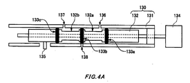
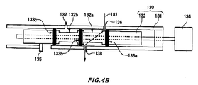
- Figs. 4A , 4B , and 4C are schematic views that describe switching of the fluid in the switching valve 130.
- the cylinder 131 includes a first flow path opening 136 connected to the first fluid path, a second flow path opening 137 connected to a second fluid path, and a third flow path opening 138 connected to a third fluid path.
- the piston 132 includes an arc-shaped first fluid path groove 132a along the periphery thereof between the O-ring 133a and the O-ring 133b, and a second fluid path groove 131b between the o-ring 133b and the o-ring 133b.
- the first flow path opening 136, the second flow path opening 137, and the third flow path opening 138 are separated by the O-rings 133a, 133b, and 133c, and when the first fluid path groove 132a and the second fluid path groove 132b are not at positions opposite each other, neither the first fluid path nor the second fluid path is connected to the third fluid path. Accordingly, neither the first fluid nor the second fluid is discharged to the third fluid path.
- Fig. 4A the first flow path opening 136, the second flow path opening 137, and the third flow path opening 138 are separated by the O-rings 133a, 133b, and 133c, and when the first fluid path groove 132a and the second fluid path groove 132b are not at positions opposite each other, neither the first fluid path nor the second fluid path is connected to the third fluid path. Accordingly, neither the first fluid nor the second fluid is discharged to the third fluid path.
- FIG. 4B is an example of the first state in which the first fluid is guided from the first elastic tube 111 to the third elastic tube 113. Furthermore, as shown in Fig. 4C , when the piston 132 slides in the cylinder 131 such that the second fluid path groove 132b moves to a position opposite the second flow path opening 137 and the third flow path opening 138, i.e. when the second flow path opening 137 and the third flow path opening 138 are at positions between the O-ring 133b and the O-ring 133c, the second fluid path and the third fluid path are connected. In this way, the second fluid is discharged from the second fluid path to the third fluid path, as shown by the arrow 182.
- the state of the piston 132 and the O-rings 133a, 133b, and 133c shown in Fig. 4C is an example of the second state in which the second fluid is guided from the second elastic tube 112 to the third elastic tube 113.
- the detector 135 that is provided to the piston 132 and protrudes outward from the cylinder 131 moves according to the movement of the piston 132, as shown in Figs. 4A , 4B , and 4C . Accordingly, by detecting the position of the detector 135 using the position sensor, the position of the piston 132 can be detected. As shown in Fig.
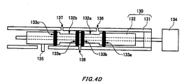
- the switching valve 130 may include the O-rings 133a, 133b, 133c, and 133d, and the piston 132 may include the arc-shaped first fluid path groove 132a between the o-ring 133a and the o-ring 133b along the periphery thereof and the second fluid path groove 131b between the o-ring 133c and the o-ring 133d. Furthermore, the switching valve 130 may be configured to include a check valve structure within the first fluid path and the second fluid path.
- Fig. 5 is an overhead view of the fluid transport driving unit 200.
- the top surface of the fluid transport driving unit 200 includes an attachment surface 202 where the fluid transport cartridge 100 is mounted and a display surface 201 with a LED display section 208 displaying information concerning the fluid to be discharged, the drive state of the fluid transport driving unit 200, and the like.
- the attachment surface 202 is positioned lower than the display surface 201. In other words, the display surface 201 protrudes upward beyond the attachment surface 202.
- the attachment surface 202 includes the cam unit 210 protruding therefrom.
- the attachment surface 202 also includes a protruding arc-shaped convex portion 220, in which the circle of the arc is centered on the rotational center of the cam unit 210.
- the fluid transport driving unit 200 includes, in the attachment surface 202, fastening holes 201a and 201b that engage respectively with the protrusions 115a and 115b provided on the fluid transport cartridge 100.
- the fluid transport driving unit 200 may have a packing rubber sheet formed of silicon rubber, for example, on the attachment surface 202.
- the packing rubber sheet functions as packaging between the attachment surface of the fluid transport driving unit 200 and the inward-facing surface of the fluid transport cartridge 100 when the fluid transport cartridge 100 is mounted in the fluid transport driving unit 200. In this way, the packing rubber sheet provides the fluid transport driving unit 200 with a drip-proof function.
- the fluid transport driving unit 200 includes a drive axle 230.
- the drive axle 230 includes a gear 230a that engages with a gear of the threaded shaft 134.
- the gear 230a of the drive axle 230 is exposed to the outside through a gear opening 203 formed in the attachment surface 202 of the fluid transport driving unit 200.
- the fluid transport driving unit 200 also includes position sensors 240a and 240b for detecting the position of the piston 132.
- the position sensors 240a and 240b are exposed to the outside through a sensor opening 204 formed in the attachment surface 202 of the fluid transport cartridge 100.
- the position sensor 240a or 240b may be formed by a photo interrupter and include a light emitting section 241 a or 241 b and a light receiving section 242a or 242b.
- the light emitted by the light emitting section 241 a or 241b may be infrared light or visible light, for example, and is received by the light receiving section 242a or 242b.
- the position of the piston 132 is detected according to the reception state of the light received by the light receiving section 242a or 242b. For example, if the light emitted by the light emitting section 241a is blocked by the detector 135 and cannot reach the light receiving section 242a, the piston 132 is in the first state.
- the piston 132 is in the second state. Accordingly, the piston 132 is determined to be in the first state or the second state based on the whether the light receiving section 242a or the light receiving section 242b receive light.
- the fluid transport driving unit 200 includes a pressure-detecting pin 250 that derives pressure of the third elastic tube 113.
- the pin 250 protrudes from the attachment surface 202.
- the tip of the pin 250 contacts the third elastic tube 113 through an insertion hole 160 formed in the external packaging member 110 of the fluid transport cartridge 100.
- the pin 250 communicates, to the pressure sensor located within the fluid transport driving unit 200, the stress corresponding to the internal force in the third elastic tube 113.
- the pressure sensor indirectly measures the pressure of the fluid flowing within the third elastic tube 113, based on the stress. In other words, the pressure sensor measures the internal pressure in the third elastic tube 113 occurring when the pump discharges, based on the stress.
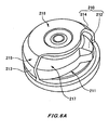
- Fig. 6A is a perspective view of the cam unit 210 of the fluid transport driving unit 200.
- the cam unit 210 includes a cam body 212 and a cam cover 214.
- the cam body 212 sequentially presses the plurality of pressing pins 140.
- the cam cover 214 covers a portion of the cam body 212.
- the cam cover 214 includes a cam opening 211, and the cam body 212 is exposed through the cam opening 211.
- the cam body 212 contacts the pressing pins 140 in the portion exposed by the cam opening 211.
- the peripheral outer surface 213 of the cam cover 214 engages with the inner peripheral surface of the cam-housing opening 150. As a result, the cam unit 210 is fixed to the fluid transport cartridge 100.
- the peripheral outer surface 213 of the cam cover 214 has a tapered surface 215 at which the diameter of the peripheral outer surface 213 decreases in a direction toward the top surface 216 of the cam cover 214.
- the peripheral outer surface of the cam body 212 has a tapered surface 217 along the tapered surface 215 of the cam cover 214.
- the tips 141 of the pressing pins 140 have semi-spherical surfaces facing the housing direction of the cam unit 210.
- the pressing pins 140 can easily slide in a radial manner relative to the rotational center of the cam unit 210, as shown in Fig. 6B .
- the fluid transport cartridge 100 can be easily attached and detached.
- the pressing pins 140 can be arranged accurately at the set positions.
- Fig. 7 shows function blocks of the fluid transport driving unit 200.
- the fluid transport driving unit 200 includes a control section 10, a cam driving section 20, a piston driving section 30, a piston position information acquiring section 40, a tube pressure information acquiring section 50, a biometric information acquiring section 60, a control information storage section 70, a receiving section 80, and a bi-directional communicating section 90.
- the cam driving section 20 operates the cam body 212 to transport to the fluid discharge portion 103 the fluid that fills the fluid paths of the mounted fluid transport cartridge 100.
- the piston driving section 30 operates the drive axle 230 to slide the piston 132 of the switching valve 130.
- the cam driving section 20 and the piston driving section 30 may be stepping motors or geared motors.
- the piston position information acquiring section 40 acquires a reception state of light, such as infrared rays, from the position sensors 240a and 240b, in order to acquire the position information of the piston 132 indicating whether the piston 132 is in the first state or the second state.
- the tube pressure information acquiring section 50 acquires the pressure information relating to the internal pressure of the third elastic tube 113, via the pressure-detecting pin 250.
- the biometric information acquiring section 60 acquires biometric information such as information relating to the blood pressure, the blood sugar level, or an electrocardiogram of the test animal via the input terminal 260.
- the biometric information acquiring section 60 may acquire the biometric information wirelessly.
- the control information storage section 70 stores control information such as setting conditions to be referenced by the control section 10 to output a piston drive signal or a cam drive signal to the piston driving section 30 or the cam driving section 20.
- the setting conditions include conditions such as discharge start time, a discharge ratio indicating the discharge amount per unit time, discharge duration, and discharge interval.
- the setting conditions are set for each of the first fluid and the second fluid.
- the receiving section 80 functions as an external connection terminal, and receives input such as the setting conditions from an external input apparatus, such as a personal computer.
- the bi-directional communicating section 90 performs wireless bi-directional communication with an external wireless terminal.
- the setting conditions may be received wirelessly from the external wireless terminal through the bi-directional communicating section 90.
- the bi-directional communicating section 90 may wirelessly transmit, to the external wireless terminal, information relating to the setting conditions or biometric information, for example.
- the control section 10 outputs the piston drive signal to the piston driving section 30 in order to align the position of the piston 132 with the fluid path of the fluid to be discharged, based on the setting conditions.
- the control section 10 determines whether the piston 132 is at the position of the fluid path of the fluid to be discharged based on the position information of the piston 132 acquired through the piston position information acquiring section 40.
- the control section 10 outputs the cam drive signal to the cam driving section 20, in order to cause the amount of fluid according to the setting conditions to be discharged.
- the fluid transport apparatus 300 can selectively output set discharge amounts for two types of fluids.
- the fluid transport apparatus 300 can selectively discharge two types of medicinal liquids.
- the fluid transport apparatus 300 can flush out the transport path connected to the fluid discharge portion 103 of the fluid transport cartridge 100 by discharging a set discharge amount of a saline solution.
- the control section 10 acquires the outputs measured by the pressure sensor and the pressure-detecting pin 250, via the tube pressure information acquiring section 50, and controls the cam driving section 20 based on the acquired outputs. For example, when a blood vessel of the test animal being injected with the fluid is obstructed, the control section 10 must stop the discharge of fluid. Therefore, the control section 10 monitors the pressure state of the third elastic tube 113 based on the pressure information from the tube pressure information acquiring section 50. When the pressure of the third elastic tube 113 is greater than or equal to a predetermined threshold value, the control section 10 determines that some kind of abnormality has occurred, such as the blood vessel of the test animal being injected with the fluid becoming obstructed, and stops the discharge of fluid.
- the fluid discharge amount discharged by the fluid transport apparatus 300 depends on the inner diameter of the third elastic tube 113 mounted in the fluid transport cartridge 100, for example.
- the inner diameter of the third elastic tube 113 has variations.
- the internal diameter also has variations according to the state of the mounted fluid transport cartridge 100.
- each fluid transport cartridge 100 has a different inner diameter. Accordingly, even when the rotation amount of the cam body 212 is the same, the fluid discharge amount discharged by the fluid transport apparatus 300 differs according to the fluid transport cartridge 100. Therefore, in order to maintain accuracy of the fluid discharge amount discharged by the fluid transport apparatus 300, the setting conditions are preferably corrected for each fluid transport cartridge 100.
- the receiving section 80 or the bi-directional communicating section 90 receive characteristic values of the mounted fluid transport cartridge 100.
- the characteristic values are correction values set for each fluid transport cartridge 100 in order to correct variation in the fluid discharge amount for the drive amount of the cam driving section 20.
- the characteristic values are correction values that correct the variation based on individual variation in components of the fluid transport cartridge 100, such as the third elastic tube 113.
- the characteristic values may be set by having the fluid transport apparatus 300 actually operate, measuring the fluid discharge amount discharged by the fluid transport apparatus 300 having the set setting conditions, and comparing the set discharge amount to the measured discharge amount.
- the cam driving section 20 acquires the characteristic values via the control section 10, and corrects the rotation amount of the cam body 212 based on the characteristic values.
- the correction values based on the characteristic values may be generated in the control section 10, and the control section 10 may output the corrected cam drive signal to the cam driving section 20.
- the total number of pulses to be output to the cam driving section 20 per unit time according to the set discharge amount can be set in advance.
- the control section 10 corrects the number of pulses per unit time corresponding to the set discharge amount, based on the characteristic values.
- the control section 10 then outputs to the cam driving section 20, which is a stepping motor, a cam drive signal corresponding to the corrected total number of pulses.
- the rotation amount of the cam body 212 can be adjusted according to individual variation in the fluid transport cartridges 100. Accordingly, variation in the discharge amount for each fluid transport cartridge 100 can be restricted.
- the control information storage section 70 may store a discharge amount table or discharge amount function indicating the total number of pulses to be output per unit time according to the discharge amount.
- the control information storage section 70 may store a correction table or correction function indicating a correction coefficient or correction number of pulses corresponding to the characteristic values.
- the control section 10 may correct the total number of pulses per unit time corresponding to the set discharge amount, based on the received characteristic values, the discharge amount function or discharge amount table, and the correction function or correction table, and output to the cam driving section 20 the cam drive signal corresponding to the corrected total number of pulses.
- Fig. 8 is a flow chart for the fluid discharge control performed by the control section 10.
- the control section 10 acquires the setting conditions and characteristic values of the equipped fluid transport cartridge 100 via the receiving section 80 (S100).
- the user may provide the control section 10 with the characteristic values through the receiving section 80, by inputting a prescribed digit number from among identification numbers allocated to the fluid transport cartridge 100, for example.
- the control section 10 references the correction function or correction table stored in the control information storage section 70, and identifies the correction number of pulses or correction coefficient corresponding to the characteristic value (S102).
- the control section 10 references the discharge amount function or discharge amount table stored in the control information storage section 70, and identifies the total number of pulses to be output per unit time corresponding to the set discharge amount shown in the setting conditions (S104).
- control section 10 corrects the identified total number of pulses, based on the identified correction number of pulses or correction coefficient (S106). For example, the control section 10 corrects the total number of pulses by adding or subtracting the correction number of pulses to or from the total number of pulses. As another example, the control section 10 may correct the total number of pulses by multiplying the total number of pulses by the correction coefficient. As yet another example, the control section 10 may correct the total number of pulses by subtracting, adding, or multiplying the correction coefficient from, to, or by a coefficient included in the discharge function for calculating the total number of pulses. The control section 10 outputs to the cam driving section 20 a cam drive signal corresponding to the corrected total number of pulses (S108). In this way, the accuracy of the fluid discharge amount discharged by the fluid transport apparatus 300 can be maintained.
- S108 corrected total number of pulses
- the control section 10 may control the fluid discharge based on the biometric information acquired via the biometric information acquiring section 60. For example, the control section 10 may periodically acquire blood pressure information relating to the blood pressure of the test animal, as biometric information. The control section 10 controls the discharge amount and discharge timing of medicinal liquid that lowers blood pressure, such that the blood pressure of the test animal remains constant, based on the blood pressure information. In this way, the fluid transport apparatus 300 can control the dosing of medicinal liquid according to change in the biological response of the test animal.
- the biometric information may include a variety of physical amounts such as bioelectric potential, blood flow, body temperature, and acceleration.
- the bi-directional communicating section 90 may wirelessly transmit the acquired biometric information to the external wireless terminal.
- the fluid transport driving unit 200 may be configured to have a control program installed therein for performing each of the processes relating to fluid discharge described above, and to have this control program executed by a computer.
- the fluid transport driving unit 200 may be configured by causing a computer to function as the control section 10, the piston position information acquiring section 40, the tube pressure information acquiring section 50, the biometric information acquiring section 60, the control information storage section 70, and the receiving section 80 as a result of executing the control program for performing each of the processes relating to fluid discharge.
- the fluid transport driving unit 200 may be controlled by wireless communication commands form the outside.
- the computer includes a CPU, an interface, a communication bus, and various memories such as a ROM, a RAM, and an EEPROM (registered trademark), and may function as the fluid transport driving unit 200 by having the CPU read and sequentially execute the processing program stored in the ROM in advance as firmware.
- reservoirs for two types of fluid can be set, and setting conditions such as discharge amount, discharge speed, and discharge time can be set respectively for each fluid type.
- the setting conditions can be wirelessly transmitted to the fluid transport apparatus 300 by remote control, as needed.
- the fluid transport cartridge 100 can be attached to and detached from the fluid transport driving unit 200. Accordingly, the fluid transport cartridge 100 filled with medicinal liquid or the like can be replaced as needed, and therefore the fluid transport cartridge 100 can always be kept clean.
- the tension in the elastic tube changes according to the arrangement state of the elastic tube, and so there is a chance that the inner diameter of the elastic tube will also change.
- exchange of the elastic tube can be realized by exchanging the fluid transport cartridge 100 in a state where the elastic tube is already arranged.
- the fluid discharge amount can then be corrected based on the set characteristic values for each fluid transport cartridge 100. Accordingly, the occurrence of errors in the fluid discharge amount caused by individual variation in the inner diameter of the elastic tubes in the fluid transport cartridges 100 can be prevented.
- the cam unit 210 is provided on the fluid transport driving unit 200 side. Accordingly, when the fluid transport cartridge 100 is removed from the fluid transport driving unit 200, the third elastic tube 113 is not pressed on by the pressing pins 140 as a result of the pressing pins 140 being pressed by the cam body 212. Accordingly, wear and tear of the third elastic tube 113 caused by deformation or compression by the pressing pins 140 can be restricted. As a result, the occurrence of errors in the fluid discharge amount can be restricted.
- the fluid transport cartridge 100 can be easily attached and detached. In this way, exchange of the fluid transport cartridge 100 can be performed more quickly, and therefore the burden placed on the test animal can be decreased. As a result, when exchanging the fluid transport cartridge 100, reduction to the accuracy of the experimental results caused by the test animal being unable to remain relaxed can be prevented.
- the switching of the fluid is realized by a piston configuration that includes grooves formed for each fluid. Accordingly, contamination of the solution in the reservoirs caused by fluid switching can be prevented.
- the pressing portion need not be formed by a plurality of pressing pins 140.
- a cam having a shape enabling movement between a first position in which the fluid delivery path is constricted by pressing from the outside of the elastic tube and a second position that does not constrict the fluid delivery path may be used.
- the third elastic tube 113 may be arranged in a straight line, and a plurality of pressing pins 140 may be arranged in a straight line along this third elastic tube 113.
- the pressing pins 140 may be sequentially pressed by spiral protrusions formed on the outer periphery of a cylindrical rotational axis.
Landscapes
- Engineering & Computer Science (AREA)
- Health & Medical Sciences (AREA)
- Mechanical Engineering (AREA)
- General Engineering & Computer Science (AREA)
- Hematology (AREA)
- Anesthesiology (AREA)
- Biomedical Technology (AREA)
- Heart & Thoracic Surgery (AREA)
- Vascular Medicine (AREA)
- Life Sciences & Earth Sciences (AREA)
- Animal Behavior & Ethology (AREA)
- General Health & Medical Sciences (AREA)
- Public Health (AREA)
- Veterinary Medicine (AREA)
- Infusion, Injection, And Reservoir Apparatuses (AREA)
- External Artificial Organs (AREA)
Description
- The present invention relates to a fluid transport driving unit and a fluid transport driving unit control program.
- Japanese Patent Application Publication No.
2011-111989 - In the fluid transport apparatus described above, a set discharge amount of the fluid is discharged through the elastic tube. However, there are cases where the set discharge amount of fluid is not accurately discharged, due to individual differences in components of the fluid transport apparatus, such as the diameter of the tube openings. Examples of how the accuracy of peristaltic pumps can be improved are disclosed in documents
US 5,695,473 ,US 4,457,751 , andJP 06317257 A - The fluid transport driving unit of the present invention comprises a driving section that causes a drive mechanism to operate to transport fluid filling a transport path of an attached fluid transport cartridge to a discharge opening of the transport path; a receiving section that receives a characteristic value set for each of a plurality of the fluid transport cartridges; and a control section that controls the driving section based on the characteristic values received by the receiving sections.
- In the fluid transport driving unit, the characteristic values may be correction values for correcting variation in discharge amount of the fluid with respect to a driving amount of the driving section. The characteristic values may be correction values for correcting variation based on individual differences among elastic tubes for forming the transport path.
- In the fluid transport driving unit, the driving section may be a cam body that moves a pressing pin pressing the elastic tube from the outside, and the control section may control a rotation amount of the cam body based on the correction values.
- The fluid transport driving unit may comprise a position fixing member that houses the cam body, is shaped as an arc relative to a rotational center of the cam body, and fixes a position relative to the fluid transport cartridge. The fluid transport driving unit may comprise a pressure sensor that measures pressure of the elastic tube. In the fluid transport driving unit, the control section may control the driving section based on output of the pressure sensor.
- The fluid transport driving unit may comprise a biometric information acquiring section that acquires biometric information of a subject to which the fluid transport driving unit is attached, and the control section may control the driving section based on the biometric information.
- The fluid transport driving unit may comprise a communicating section that wirelessly acquires a setting condition for controlling the driving section, and the control section may control the driving section based on the setting condition.
- A fluid transport driving unit control program according to the present invention causes a computer to receive a characteristic value set for an attached fluid transport cartridge; and control a driving section, which causes a drive mechanism to operate to discharge fluid filling a transport path of the fluid transport cartridge to a discharge opening, based on the received characteristic value.
- The summary clause does not necessarily describe all necessary features of the embodiments of the present invention. The present invention may also be a subcombination of the features described above.
-
-
Fig. 1 shows an exemplary usable form of a fluid transport apparatus according to the present embodiment. -
Fig. 2 is an overhead view of the fluid transport apparatus according to the present embodiment. -
Fig. 3 is a schematic view of the internal structure of the fluid transport cartridge according to the present embodiment. -
Fig. 4A is a schematic view for describing switching of the fluid by the switching valve. -
Fig. 4B is a schematic view for describing switching of the fluid by the switching valve. -
Fig. 4C is a schematic view for describing switching of the fluid by the switching valve. -
Fig. 4D is a schematic view for describing a modification of switching of the fluid by the switching valve. -
Fig. 5 is an overhead view of the fluid transport driving unit. -
Fig. 6A is a perspective view of the cam of the fluid transport driving unit. -
Fig. 6B is a schematic view for describing a tapered surface of the cam body and semi-spherical surface of a pressing pin. -
Fig. 7 shows function blocks of the fluid transport driving unit. -
Fig. 8 is a flow chart for the fluid discharge control performed by the control section. - Hereinafter, an embodiment of the present invention will be described. The embodiment does not limit the invention according to the claims, and all the combinations of the features described in the embodiment are not necessarily essential to means provided by aspects of the invention.
-
Fig. 1 shows an exemplary usable form of afluid transport apparatus 300 according to an embodiment of the present invention. Thefluid transport apparatus 300 is fixed to testclothing 310 that is worn by a test animal serving as a test subject, such as a dog or monkey. Thefluid transport apparatus 300 injects fluid such as medicine into the body of the test animal, in units of a discharge amount determined according to predetermined setting conditions. The setting conditions are programmed to include conditions such as discharge start time, a discharge ratio indicating the discharge amount per unit time, discharge duration, and discharge interval. If necessary, the setting conditions can be changed by remote operation via wireless communication. - The fluid is not limited to fluids such as medicine, saline solution, and nutrient solution, and may be gas or gel that includes the component to be discharged. The
fluid transport apparatus 300 has a size that enables a medium-sized pet or test animal to move while wearing thefluid transport apparatus 300, and therefore the subject wearing thefluid transport apparatus 300 is not limited to a test animal, and can be a human instead. By having a human wear thefluid transport apparatus 300, medicinal fluid can be provided periodically or at planned times to living tissue, such as blood vessels or muscles, for example. -
Fig. 2 is an overhead view of thefluid transport apparatus 300. Thefluid transport apparatus 300 includes afluid transport cartridge 100 and a fluidtransport driving unit 200. Thefluid transport apparatus 300 can selectively discharge two types of fluid. Thefluid transport cartridge 100 is fixed in a detachable manner to the fluidtransport driving unit 200. Thefluid transport cartridge 100 includes a firstfluid inflow portion 101, a secondfluid inflow portion 102, and afluid discharge portion 103. The firstfluid inflow portion 101 is connected to an external first reservoir that contains a first fluid. The secondfluid inflow portion 102 is connected to a second reservoir that contains a second fluid. Thefluid discharge portion 103 is connected to an inflow tube for introducing the first fluid and the second fluid into the body of the test animal. - The fluid
transport driving unit 200 includes acam unit 210. Thecam unit 210 includes acam body 212 that provides rotational drive and acam cover 214 that houses thecam body 212. Thecam unit 210 is a drive mechanism that guides the first fluid or the second fluid from the firstfluid inflow portion 101 or the secondfluid inflow portion 102 to thefluid discharge portion 103. Thecam unit 210 of the fluidtransport driving unit 200 also functions to fix the position of thefluid transport cartridge 100. Thecam cover 214 of thecam unit 210 is shaped as an arc around a rotational center, and when thefluid transport cartridge 100 is to be fixed, thecam cover 214 sets the position of thefluid transport cartridge 100 relative to the fluidtransport driving unit 200. - Furthermore, the fluid
transport driving unit 200 includes aninput terminal 260 for acquiring biometric information relating to the test animal. The biometric information is information relating to an electrocardiogram or information relating to the blood pressure of the test animal, for example. The biometric information may be used to control discharge of the fluid. If the discharge of the fluid is not controlled according to the biometric information, theinput terminal 260 need not be provided. The fluidtransport driving unit 200 includes afirst hook 205 and asecond hook 206 for fixing thefluid transport cartridge 100. Thefirst hook 205 fixes oneedge 110a of thefluid transport cartridge 100 between the firstfluid inflow portion 101 and the secondfluid inflow portion 102. Thesecond hook 206 fixes oneedge 110b of thefluid transport cartridge 100 where thefluid discharge portion 103 is provided. Thefluid transport cartridge 100 and the fluidtransport driving unit 200 are fixed by the lockingmember 154. In this way, by fixing thefluid transport cartridge 100 on two edges together with the lockingmember 154, thefluid transport cartridge 100 is prevented from falling from the fluidtransport driving unit 200. Furthermore, when thefluid transport cartridge 100 is to be removed, the lockingmember 154 is released and thefirst hook 205 is pressed by the thumb of the right hand, for example, while pressing thesecond hook 206 with another finger of the right hand, and thefluid transport cartridge 100 can then be removed by the left hand. Accordingly, thefluid transport cartridge 100 can be easily detached from the fluidtransport driving unit 200. In this way, by including different fixing functions such as thefirst hook 205, thesecond hook 206, and the lockingmember 154 in thefluid transport apparatus 300, when thefluid transport apparatus 300 is worn by a primate such as a monkey, thefluid transport cartridge 100 can be prevented from falling off as a result of the primate touching thefluid transport cartridge 100. -
Fig. 3 is a schematic view of the internal structure of thefluid transport cartridge 100. Thefluid transport cartridge 100 includes anexternal packaging member 110, a firstelastic tube 111, a secondelastic tube 112, a switchingvalve 130, a threadedshaft 134, a thirdelastic tube 113, and a plurality of pressing pins 140. Theexternal packaging member 110 houses the firstelastic tube 111, the secondelastic tube 112, the switchingvalve 130, the threadedshaft 134, the thirdelastic tube 113, and the plurality of pressing pins 140. In theexternal packaging member 110, at least the outward-facing surface that is opposite the inward-facing surface facing the fluidtransport driving unit 200 is transparent. The lockingmember 154 for fixing thefluid transport cartridge 100 to the fluidtransport driving unit 200 is provided in theexternal packaging member 110. The contour of theexternal packaging member 110 as seen from the outward-facing surface or inward-facing surface of thefluid transport cartridge 100 is substantially rectangular, in the portion not including the firstfluid inflow portion 101, the secondfluid inflow portion 102, and thefluid discharge portion 103, and is fixed to the fluidtransport driving unit 200 at two edges of the rectangular contour. Among these two edges, theedge 110a is provided between the firstfluid inflow portion 101 and the secondfluid inflow portion 102, and theedge 110b is provided with thefluid discharge portion 103. Theexternal packaging member 110 includes afirst fastening portion 116a to which thefirst hook 205 is fixed, on theedge 110a. Theexternal packaging member 110 includes asecond fastening portion 116b to which thesecond hook 206 is fixed, on theedge 110b. - The first
elastic tube 111 forms a first fluid path that is arranged along afirst groove 121 formed in theexternal packaging member 110. One end of the firstelastic tube 111 is connected to the firstfluid inflow portion 101, and the other end is connected to the switchingvalve 130. The firstelastic tube 111 delivers the first fluid introduced through the firstfluid inflow portion 101 from the first reservoir to the switchingvalve 130. The secondelastic tube 112 forms a second fluid path that is arranged along asecond groove 122 formed in theexternal packaging member 110. One end of the secondelastic tube 112 is connected to the secondfluid inflow portion 102, and the other end is connected to the switchingvalve 130. The secondelastic tube 112 delivers the second fluid introduced through the secondfluid inflow portion 102 from the second reservoir to the switchingvalve 130. The thirdelastic tube 113 forms a third fluid path that is arranged along athird groove 123 formed in theexternal packaging member 110. One end of the thirdelastic tube 113 is connected to the switchingvalve 130, and the other end is connected to thefluid discharge portion 103. The thirdelastic tube 113 delivers the first fluid and the second fluid introduced through the switchingvalve 130 to thefluid discharge portion 103. The firstfluid inflow portion 101, the secondfluid inflow portion 102, and thefluid discharge portion 103 may be Luer-Lok style connectors, which are easily detachable. - The switching
valve 130 guides one of the first fluid and the second fluid to thefluid discharge portion 103. The switchingvalve 130 includes acylinder 131, apiston 132, and O-rings cylinder 131 is connected to the firstelastic tube 111, the secondelastic tube 112, and the thirdelastic tube 113. Thepiston 132 engages through the O-rings cylinder 131 to move between a first state in which the first fluid is guided from the firstelastic tube 111 to the thirdelastic tube 113 and a second state in which the second fluid is guided from the secondelastic tube 112 to the thirdelastic tube 113. The threadedshaft 134 engages within thepiston 132, and forms a ball screw together with thepiston 132 and the O-rings shaft 134 on a central axis, thepiston 132 and the O-rings cylinder 131, thereby moving between the first state and the second state. - The
piston 132 includes adetector 135. Thedetector 135 protrudes from an opening formed in the inward-facing surface of theexternal packaging member 110, through an opening formed in thecylinder 131. A position sensor of the fluidtransport driving unit 200 detects thedetector 135, thereby detecting the position of thepiston 132. The detection results are provided to the fluidtransport driving unit 200, and aLED display section 208 of the fluidtransport driving unit 200 displays the detection results. By viewing the state of theLED display section 208, a user can confirm which of the first fluid and the second fluid is selected as the fluid to be discharged. Furthermore, the O-rings piston 132 is in the first state or the second state. Thecylinder 131 is transparent, in the same manner as the outward-facing surface of theexternal packaging member 110. Accordingly, the O-rings piston 132 can be seen from outside theexternal packaging member 110. Accordingly, by viewing the O-rings fluid transport cartridge 100 is mounted in the fluidtransport driving unit 200, the user can check whether thepiston 132 is in the first state or the second state. In other words, by viewing the O-rings - The
external packaging member 110 includes aninsertion hole 160 near thefluid discharge portion 103 on the inward-facing surface of thethird groove 123 that faces the fluidtransport driving unit 200. A pressure detecting pin is inserted into theinsertion hole 160 in order to measure pressure of the thirdelastic tube 113. Furthermore, theexternal packaging member 110 includes a cam-housing opening 150 serving as a position fixing member, along with thecam unit 210, at a position opposite thecam unit 210 serving as a position fixing member on the unit side when theexternal packaging member 110 is mounted on the fluidtransport driving unit 200. The cam-housing opening 150 is a through-hole that contacts the periphery of thecam unit 210. Theexternal packaging member 110 includesprotrusions transport driving unit 200. Theprotrusions transport driving unit 200. In this way, positional misalignment between thefluid transport cartridge 100 and the fluidtransport driving unit 200 is restricted. Furthermore, theexternal packaging member 110 includes a through-hole 152. A convex portion provided on the fluidtransport driving unit 200 engages with the through-hole 152. - The
pressing pins 140 are examples of a pressing portion that moves between a first position in which the thirdelastic tube 113 is pressed from the outside to constrict the fluid delivery path and a second position that does not constrict the fluid delivery path. Thepressing pins 140 are arranged along apin guiding groove 124 formed in theexternal packaging member 110. Thepressing pins 140 are arranged along the thirdelastic tube 113 in the transport direction of the fluid, at uniform intervals in a radial manner centered on the rotational center of thecam unit 210. The tips of thepressing pins 140 protrude toward the cam-housing opening 150 in a direction toward the center of the cam-housing opening 150. Furthermore, the tips of thepressing pins 140 have semi-spherical surfaces oriented in a direction opposite the housing direction of thecam unit 210. By including such semi-spherical surfaces, when thecam unit 210 is housed in the cam-housing opening 150, friction between the tips of thepressing pins 140 and the side surface of thecam body 212 is decreased, and thepressing pins 140 can be arranged reliably at set positions. - Furthermore, when the
pressing pins 140 arranged in thepin guiding groove 124 are seen from the outside, the tip portions of thepressing pins 140 are tapered to have a fine tip. In this way, thepressing pins 140 can be arranged radially in a small mounting space. Since the tips of thepressing pins 140 are tapered, the contact surface area between thecam body 212 and thepressing pins 140 is decreased, and the sliding resistance experienced when thecam body 212 is rotationally driven can be decreased. The cam-housing opening 150 is shaped as an arc centered on the rotational center of thecam unit 210. In this way, when thefluid transport cartridge 100 is mounted in the fluidtransport driving unit 200, the center of the arc-shaped cam-housing opening 150 can be matched to the rotational center of thecam unit 210. Since the center of the arc-shaped cam-housing opening 150 is matched to the rotational center of thecam unit 210, when thecam unit 210 is rotationally driven while being housed in the cam-housing opening 150, positional misalignment between thefluid transport cartridge 100 and thecam unit 210 can be prevented. Furthermore, since the center of the arc-shaped cam-housing opening 150 is matched to the rotational center of thecam unit 210, thepressing pins 140 can sequentially press the thirdelastic tube 113 with a uniform force in response to the rotational drive of thecam body 212. Accordingly, in response to driving of thecam body 212, thepressing pins 140 can accurately press the thirdelastic tube 113. As a result, the precise set discharge amount of the fluid can be discharged. - In a state where the
fluid transport cartridge 100 is mounted in the fluidtransport driving unit 200, thepressing pins 140 move between the first position in which the thirdelastic tube 113 is pressed from the outside in the radial direction to constrict the fluid delivery path and the second position that does not constrict the fluid delivery path, thereby delivering fluid from the upstream side to the downstream side, according to the driving of thecam body 212. In other words, in response to the driving of thecam body 212, thepressing pins 140 sequentially press the thirdelastic tube 113 from the upstream side to the downstream side, thereby causing the thirdelastic tube 113 to move peristaltically and deliver the fluid from the upstream side to the downstream side. - On the other hand, when the
fluid transport cartridge 100 is removed from the fluidtransport driving unit 200, i.e. when the cam-housing opening 150 is not housing thecam unit 210, thepressing pins 140 do not press on the thirdelastic tube 113. In other words, when the cam-housing opening 150 is not housing thecam unit 210, thepressing pins 140 are located at the second position in which the elastic force of the thirdelastic tube 113 causes the fluid path to not be constricted. In this way, when thefluid transport apparatus 300 is not being used, by removing thefluid transport cartridge 100 from the fluidtransport driving unit 200, the thirdelastic tube 113 can be kept in a state of not being pressed upon by any of the pressing pins 140. Accordingly, by maintaining the state in which the thirdelastic tube 113 is not being pressed upon by any of thepressing pins 140, wear and tear on the thirdelastic tube 113 can be prevented from progressing. - The
cam unit 210, which is the drive mechanism causing thepressing pins 140 to exert pressure, is provided in fluidtransport driving unit 200. Thecam unit 210 should rotate accurately in order to accurately discharge the set discharge amount of fluid. If thecam unit 210 is provided in thefluid transport cartridge 100, thecam unit 210 should be accurately fixed at a predetermined position every time thefluid transport cartridge 100 is worn. However, it is difficult to accurately fix thecam unit 210 at the predetermined position. Therefore, by providing thecam unit 210 in the fluidtransport driving unit 200, positional misalignment of thecam unit 210 occurring every time thefluid transport cartridge 100 is worn can be prevented. In this way, variations in the fluid discharge amount every time thefluid transport cartridge 100 is worn can be prevented. - The
fluid transport cartridge 100 can be attached to and detached from the fluidtransport driving unit 200. Therefore, thefluid transport cartridge 100 is a consumable product that can be replaced as needed. Accordingly, by replacing thefluid transport cartridge 100 after a set number of uses, for example, the cleanliness of thefluid transport cartridge 100 can be maintained. -
Figs. 4A ,4B , and4C are schematic views that describe switching of the fluid in the switchingvalve 130. Thecylinder 131 includes a first flow path opening 136 connected to the first fluid path, a second flow path opening 137 connected to a second fluid path, and a third flow path opening 138 connected to a third fluid path. Thepiston 132 includes an arc-shaped firstfluid path groove 132a along the periphery thereof between the O-ring 133a and the O-ring 133b, and a second fluid path groove 131b between the o-ring 133b and the o-ring 133b. - As shown in
Fig. 4A , the first flow path opening 136, the second flow path opening 137, and the third flow path opening 138 are separated by the O-rings fluid path groove 132a and the secondfluid path groove 132b are not at positions opposite each other, neither the first fluid path nor the second fluid path is connected to the third fluid path. Accordingly, neither the first fluid nor the second fluid is discharged to the third fluid path. On the other hand, as shown inFig. 4B , when thepiston 132 and the O-rings cylinder 131 such that the firstfluid path groove 132a moves to a position opposite the first flow path opening 136 and the third flow path opening 138, i.e. when the first flow path opening 136 and the third flow path opening 138 are positioned between the o-ring 133a and the o-ring 133b, the first fluid path and the third fluid path are connected. Therefore, the first fluid is discharged from the first fluid path to the third fluid path, as shown by thearrow 181. In other words, the state of thepiston 132 and the O-rings Fig. 4B is an example of the first state in which the first fluid is guided from the firstelastic tube 111 to the thirdelastic tube 113. Furthermore, as shown inFig. 4C , when thepiston 132 slides in thecylinder 131 such that the secondfluid path groove 132b moves to a position opposite the second flow path opening 137 and the third flow path opening 138, i.e. when the second flow path opening 137 and the third flow path opening 138 are at positions between the O-ring 133b and the O-ring 133c, the second fluid path and the third fluid path are connected. In this way, the second fluid is discharged from the second fluid path to the third fluid path, as shown by thearrow 182. In other words, the state of thepiston 132 and the O-rings Fig. 4C is an example of the second state in which the second fluid is guided from the secondelastic tube 112 to the thirdelastic tube 113. - The
detector 135 that is provided to thepiston 132 and protrudes outward from thecylinder 131 moves according to the movement of thepiston 132, as shown inFigs. 4A ,4B , and4C . Accordingly, by detecting the position of thedetector 135 using the position sensor, the position of thepiston 132 can be detected. As shown inFig. 4D , the switchingvalve 130 may include the O-rings piston 132 may include the arc-shaped firstfluid path groove 132a between the o-ring 133a and the o-ring 133b along the periphery thereof and the second fluid path groove 131b between the o-ring 133c and the o-ring 133d. Furthermore, the switchingvalve 130 may be configured to include a check valve structure within the first fluid path and the second fluid path. -
Fig. 5 is an overhead view of the fluidtransport driving unit 200. The top surface of the fluidtransport driving unit 200 includes anattachment surface 202 where thefluid transport cartridge 100 is mounted and adisplay surface 201 with aLED display section 208 displaying information concerning the fluid to be discharged, the drive state of the fluidtransport driving unit 200, and the like. Theattachment surface 202 is positioned lower than thedisplay surface 201. In other words, thedisplay surface 201 protrudes upward beyond theattachment surface 202. Furthermore, theattachment surface 202 includes thecam unit 210 protruding therefrom. Theattachment surface 202 also includes a protruding arc-shapedconvex portion 220, in which the circle of the arc is centered on the rotational center of thecam unit 210. When thefluid transport cartridge 100 is mounted on theattachment surface 202, the outward-facing surface of thefluid transport cartridge 100 and thedisplay surface 201 are in substantially the same plane. The fluidtransport driving unit 200 includes, in theattachment surface 202,fastening holes protrusions fluid transport cartridge 100. The fluidtransport driving unit 200 may have a packing rubber sheet formed of silicon rubber, for example, on theattachment surface 202. The packing rubber sheet functions as packaging between the attachment surface of the fluidtransport driving unit 200 and the inward-facing surface of thefluid transport cartridge 100 when thefluid transport cartridge 100 is mounted in the fluidtransport driving unit 200. In this way, the packing rubber sheet provides the fluidtransport driving unit 200 with a drip-proof function. - The fluid
transport driving unit 200 includes adrive axle 230. Thedrive axle 230 includes agear 230a that engages with a gear of the threadedshaft 134. Thegear 230a of thedrive axle 230 is exposed to the outside through agear opening 203 formed in theattachment surface 202 of the fluidtransport driving unit 200. The fluidtransport driving unit 200 also includesposition sensors piston 132. Theposition sensors sensor opening 204 formed in theattachment surface 202 of thefluid transport cartridge 100. Theposition sensor light emitting section light receiving section light emitting section light receiving section piston 132 is detected according to the reception state of the light received by thelight receiving section light emitting section 241a is blocked by thedetector 135 and cannot reach thelight receiving section 242a, thepiston 132 is in the first state. On the other hand, if the light emitted by thelight emitting section 241b is block by thedetector 135 and cannot reach thelight receiving section 242b, thepiston 132 is in the second state. Accordingly, thepiston 132 is determined to be in the first state or the second state based on the whether thelight receiving section 242a or thelight receiving section 242b receive light. - The fluid
transport driving unit 200 includes a pressure-detectingpin 250 that derives pressure of the thirdelastic tube 113. Thepin 250 protrudes from theattachment surface 202. When thefluid transport cartridge 100 is mounted, the tip of thepin 250 contacts the thirdelastic tube 113 through aninsertion hole 160 formed in theexternal packaging member 110 of thefluid transport cartridge 100. In this way, thepin 250 communicates, to the pressure sensor located within the fluidtransport driving unit 200, the stress corresponding to the internal force in the thirdelastic tube 113. The pressure sensor indirectly measures the pressure of the fluid flowing within the thirdelastic tube 113, based on the stress. In other words, the pressure sensor measures the internal pressure in the thirdelastic tube 113 occurring when the pump discharges, based on the stress. -
Fig. 6A is a perspective view of thecam unit 210 of the fluidtransport driving unit 200. Thecam unit 210 includes acam body 212 and acam cover 214. Thecam body 212 sequentially presses the plurality of pressing pins 140. Thecam cover 214 covers a portion of thecam body 212. Thecam cover 214 includes acam opening 211, and thecam body 212 is exposed through thecam opening 211. Thecam body 212 contacts thepressing pins 140 in the portion exposed by thecam opening 211. When thefluid transport cartridge 100 is mounted on the fluidtransport driving unit 200, the peripheralouter surface 213 of thecam cover 214 engages with the inner peripheral surface of the cam-housing opening 150. As a result, thecam unit 210 is fixed to thefluid transport cartridge 100. Furthermore, the peripheralouter surface 213 of thecam cover 214 has a taperedsurface 215 at which the diameter of the peripheralouter surface 213 decreases in a direction toward thetop surface 216 of thecam cover 214. By providing thecam cover 214 with thetapered surface 215 in this manner, thecam unit 210 can be easily housed in the cam-housing opening 150. The peripheral outer surface of thecam body 212 has a taperedsurface 217 along the taperedsurface 215 of thecam cover 214. Furthermore, as described above, the tips 141 of thepressing pins 140 have semi-spherical surfaces facing the housing direction of thecam unit 210. By using the tapered structure for thecam body 212 and the semi-spherical structure for thepressing pins 140 in this manner, when thecam unit 210 is housed in the cam-housing opening 150, while pressing thepressing pins 140 along the taperedsurface 217 of thecam body 212 and maintaining thepressing pins 140 in a parallel state with respect to the inward-facing surface of thefluid transport cartridge 100, thepressing pins 140 can easily slide in a radial manner relative to the rotational center of thecam unit 210, as shown inFig. 6B . As a result, thefluid transport cartridge 100 can be easily attached and detached. Furthermore, when thefluid transport cartridge 100 is mounted in the fluidtransport driving unit 200, thepressing pins 140 can be arranged accurately at the set positions. -
Fig. 7 shows function blocks of the fluidtransport driving unit 200. The fluidtransport driving unit 200 includes a control section 10, acam driving section 20, apiston driving section 30, a piston positioninformation acquiring section 40, a tube pressureinformation acquiring section 50, a biometricinformation acquiring section 60, a controlinformation storage section 70, a receivingsection 80, and a bi-directional communicatingsection 90. - The
cam driving section 20 operates thecam body 212 to transport to thefluid discharge portion 103 the fluid that fills the fluid paths of the mountedfluid transport cartridge 100. When switching the fluid to be discharged, thepiston driving section 30 operates thedrive axle 230 to slide thepiston 132 of the switchingvalve 130. Thecam driving section 20 and thepiston driving section 30 may be stepping motors or geared motors. - The piston position
information acquiring section 40 acquires a reception state of light, such as infrared rays, from theposition sensors piston 132 indicating whether thepiston 132 is in the first state or the second state. The tube pressureinformation acquiring section 50 acquires the pressure information relating to the internal pressure of the thirdelastic tube 113, via the pressure-detectingpin 250. The biometricinformation acquiring section 60 acquires biometric information such as information relating to the blood pressure, the blood sugar level, or an electrocardiogram of the test animal via theinput terminal 260. The biometricinformation acquiring section 60 may acquire the biometric information wirelessly. The controlinformation storage section 70 stores control information such as setting conditions to be referenced by the control section 10 to output a piston drive signal or a cam drive signal to thepiston driving section 30 or thecam driving section 20. The setting conditions include conditions such as discharge start time, a discharge ratio indicating the discharge amount per unit time, discharge duration, and discharge interval. The setting conditions are set for each of the first fluid and the second fluid. The receivingsection 80 functions as an external connection terminal, and receives input such as the setting conditions from an external input apparatus, such as a personal computer. The bi-directional communicatingsection 90 performs wireless bi-directional communication with an external wireless terminal. The setting conditions may be received wirelessly from the external wireless terminal through the bi-directional communicatingsection 90. The bi-directional communicatingsection 90 may wirelessly transmit, to the external wireless terminal, information relating to the setting conditions or biometric information, for example. - The control section 10 outputs the piston drive signal to the
piston driving section 30 in order to align the position of thepiston 132 with the fluid path of the fluid to be discharged, based on the setting conditions. The control section 10 determines whether thepiston 132 is at the position of the fluid path of the fluid to be discharged based on the position information of thepiston 132 acquired through the piston positioninformation acquiring section 40. When thepiston 132 is at the position of the fluid path of the fluid to be discharged, the control section 10 outputs the cam drive signal to thecam driving section 20, in order to cause the amount of fluid according to the setting conditions to be discharged. In this way, thefluid transport apparatus 300 can selectively output set discharge amounts for two types of fluids. For example, thefluid transport apparatus 300 can selectively discharge two types of medicinal liquids. After the set discharge amount of a first type of medicinal liquid is discharged, thefluid transport apparatus 300 can flush out the transport path connected to thefluid discharge portion 103 of thefluid transport cartridge 100 by discharging a set discharge amount of a saline solution. - The control section 10 acquires the outputs measured by the pressure sensor and the pressure-detecting
pin 250, via the tube pressureinformation acquiring section 50, and controls thecam driving section 20 based on the acquired outputs. For example, when a blood vessel of the test animal being injected with the fluid is obstructed, the control section 10 must stop the discharge of fluid. Therefore, the control section 10 monitors the pressure state of the thirdelastic tube 113 based on the pressure information from the tube pressureinformation acquiring section 50. When the pressure of the thirdelastic tube 113 is greater than or equal to a predetermined threshold value, the control section 10 determines that some kind of abnormality has occurred, such as the blood vessel of the test animal being injected with the fluid becoming obstructed, and stops the discharge of fluid. - The fluid discharge amount discharged by the
fluid transport apparatus 300 depends on the inner diameter of the thirdelastic tube 113 mounted in thefluid transport cartridge 100, for example. However, the inner diameter of the thirdelastic tube 113 has variations. The internal diameter also has variations according to the state of the mountedfluid transport cartridge 100. In other words, eachfluid transport cartridge 100 has a different inner diameter. Accordingly, even when the rotation amount of thecam body 212 is the same, the fluid discharge amount discharged by thefluid transport apparatus 300 differs according to thefluid transport cartridge 100. Therefore, in order to maintain accuracy of the fluid discharge amount discharged by thefluid transport apparatus 300, the setting conditions are preferably corrected for eachfluid transport cartridge 100. - To this end, the receiving
section 80 or the bi-directional communicatingsection 90 receive characteristic values of the mountedfluid transport cartridge 100. The characteristic values are correction values set for eachfluid transport cartridge 100 in order to correct variation in the fluid discharge amount for the drive amount of thecam driving section 20. The characteristic values are correction values that correct the variation based on individual variation in components of thefluid transport cartridge 100, such as the thirdelastic tube 113. The characteristic values may be set by having thefluid transport apparatus 300 actually operate, measuring the fluid discharge amount discharged by thefluid transport apparatus 300 having the set setting conditions, and comparing the set discharge amount to the measured discharge amount. Thecam driving section 20 acquires the characteristic values via the control section 10, and corrects the rotation amount of thecam body 212 based on the characteristic values. In this way, the control items from the control section 10 can be simplified, and problems resulting from errors in the discharge amount can easily be discovered. The correction values based on the characteristic values may be generated in the control section 10, and the control section 10 may output the corrected cam drive signal to thecam driving section 20. - For example, the total number of pulses to be output to the
cam driving section 20 per unit time according to the set discharge amount can be set in advance. In this case, the control section 10 corrects the number of pulses per unit time corresponding to the set discharge amount, based on the characteristic values. The control section 10 then outputs to thecam driving section 20, which is a stepping motor, a cam drive signal corresponding to the corrected total number of pulses. In this way, the rotation amount of thecam body 212 can be adjusted according to individual variation in thefluid transport cartridges 100. Accordingly, variation in the discharge amount for eachfluid transport cartridge 100 can be restricted. - The control
information storage section 70 may store a discharge amount table or discharge amount function indicating the total number of pulses to be output per unit time according to the discharge amount. The controlinformation storage section 70 may store a correction table or correction function indicating a correction coefficient or correction number of pulses corresponding to the characteristic values. When the receivingsection 80 receives the characteristic values of the mountedfluid transport cartridge 100, the control section 10 may correct the total number of pulses per unit time corresponding to the set discharge amount, based on the received characteristic values, the discharge amount function or discharge amount table, and the correction function or correction table, and output to thecam driving section 20 the cam drive signal corresponding to the corrected total number of pulses. -
Fig. 8 is a flow chart for the fluid discharge control performed by the control section 10. The control section 10 acquires the setting conditions and characteristic values of the equippedfluid transport cartridge 100 via the receiving section 80 (S100). The user may provide the control section 10 with the characteristic values through the receivingsection 80, by inputting a prescribed digit number from among identification numbers allocated to thefluid transport cartridge 100, for example. Next, the control section 10 references the correction function or correction table stored in the controlinformation storage section 70, and identifies the correction number of pulses or correction coefficient corresponding to the characteristic value (S102). Furthermore, the control section 10 references the discharge amount function or discharge amount table stored in the controlinformation storage section 70, and identifies the total number of pulses to be output per unit time corresponding to the set discharge amount shown in the setting conditions (S104). In addition, the control section 10 corrects the identified total number of pulses, based on the identified correction number of pulses or correction coefficient (S106). For example, the control section 10 corrects the total number of pulses by adding or subtracting the correction number of pulses to or from the total number of pulses. As another example, the control section 10 may correct the total number of pulses by multiplying the total number of pulses by the correction coefficient. As yet another example, the control section 10 may correct the total number of pulses by subtracting, adding, or multiplying the correction coefficient from, to, or by a coefficient included in the discharge function for calculating the total number of pulses. The control section 10 outputs to the cam driving section 20 a cam drive signal corresponding to the corrected total number of pulses (S108). In this way, the accuracy of the fluid discharge amount discharged by thefluid transport apparatus 300 can be maintained. - The control section 10 may control the fluid discharge based on the biometric information acquired via the biometric
information acquiring section 60. For example, the control section 10 may periodically acquire blood pressure information relating to the blood pressure of the test animal, as biometric information. The control section 10 controls the discharge amount and discharge timing of medicinal liquid that lowers blood pressure, such that the blood pressure of the test animal remains constant, based on the blood pressure information. In this way, thefluid transport apparatus 300 can control the dosing of medicinal liquid according to change in the biological response of the test animal. The biometric information may include a variety of physical amounts such as bioelectric potential, blood flow, body temperature, and acceleration. The bi-directional communicatingsection 90 may wirelessly transmit the acquired biometric information to the external wireless terminal. - The fluid
transport driving unit 200 according to the present embodiment may be configured to have a control program installed therein for performing each of the processes relating to fluid discharge described above, and to have this control program executed by a computer. In other words, the fluidtransport driving unit 200 may be configured by causing a computer to function as the control section 10, the piston positioninformation acquiring section 40, the tube pressureinformation acquiring section 50, the biometricinformation acquiring section 60, the controlinformation storage section 70, and the receivingsection 80 as a result of executing the control program for performing each of the processes relating to fluid discharge. As another example, the fluidtransport driving unit 200 may be controlled by wireless communication commands form the outside. - The computer includes a CPU, an interface, a communication bus, and various memories such as a ROM, a RAM, and an EEPROM (registered trademark), and may function as the fluid
transport driving unit 200 by having the CPU read and sequentially execute the processing program stored in the ROM in advance as firmware. - According to the
fluid transport apparatus 300 of the present embodiment described above, reservoirs for two types of fluid can be set, and setting conditions such as discharge amount, discharge speed, and discharge time can be set respectively for each fluid type. The setting conditions can be wirelessly transmitted to thefluid transport apparatus 300 by remote control, as needed. - The
fluid transport cartridge 100 can be attached to and detached from the fluidtransport driving unit 200. Accordingly, thefluid transport cartridge 100 filled with medicinal liquid or the like can be replaced as needed, and therefore thefluid transport cartridge 100 can always be kept clean. When replacing only the elastic tube due to wear and tear, the tension in the elastic tube changes according to the arrangement state of the elastic tube, and so there is a chance that the inner diameter of the elastic tube will also change. However, with the present embodiment, exchange of the elastic tube can be realized by exchanging thefluid transport cartridge 100 in a state where the elastic tube is already arranged. The fluid discharge amount can then be corrected based on the set characteristic values for eachfluid transport cartridge 100. Accordingly, the occurrence of errors in the fluid discharge amount caused by individual variation in the inner diameter of the elastic tubes in thefluid transport cartridges 100 can be prevented. - In addition, the
cam unit 210 is provided on the fluidtransport driving unit 200 side. Accordingly, when thefluid transport cartridge 100 is removed from the fluidtransport driving unit 200, the thirdelastic tube 113 is not pressed on by thepressing pins 140 as a result of thepressing pins 140 being pressed by thecam body 212. Accordingly, wear and tear of the thirdelastic tube 113 caused by deformation or compression by thepressing pins 140 can be restricted. As a result, the occurrence of errors in the fluid discharge amount can be restricted. - Furthermore, by providing semi-spherical surfaces on the tips of the
pressing pins 140 and tapered surfaces on the side surface of thecam body 212, thefluid transport cartridge 100 can be easily attached and detached. In this way, exchange of thefluid transport cartridge 100 can be performed more quickly, and therefore the burden placed on the test animal can be decreased. As a result, when exchanging thefluid transport cartridge 100, reduction to the accuracy of the experimental results caused by the test animal being unable to remain relaxed can be prevented. - The switching of the fluid is realized by a piston configuration that includes grooves formed for each fluid. Accordingly, contamination of the solution in the reservoirs caused by fluid switching can be prevented.
- In the above embodiment, the pressing portion need not be formed by a plurality of pressing pins 140. Instead of the pressing pins, for example, a cam having a shape enabling movement between a first position in which the fluid delivery path is constricted by pressing from the outside of the elastic tube and a second position that does not constrict the fluid delivery path may be used. Furthermore, the third
elastic tube 113 may be arranged in a straight line, and a plurality ofpressing pins 140 may be arranged in a straight line along this thirdelastic tube 113. In this case, thepressing pins 140 may be sequentially pressed by spiral protrusions formed on the outer periphery of a cylindrical rotational axis. - The operations, procedures, steps, and stages of each process performed by an apparatus, system, program, and method shown in the claims, embodiments, or diagrams can be performed in any order as long as the order is not indicated by "prior to," "before," or the like and as long as the output from a previous process is not used in a later process. Even if the process flow is described using phrases such as "first" or "next" in the claims, embodiments, or diagrams, it does not necessarily mean that the process must be performed in this order.
-
- 10: control section, 20: cam driving section, 30: piston driving section, 40: piston position information acquiring section, 50: tube pressure information acquiring section, 60: biometric information acquiring section, 70: control information storage section, 80: receiving section, 90: bi-directional communicating section, 100: fluid transport cartridge, 101: first fluid inflow portion, 102: second fluid inflow portion, 103: fluid discharge portion, 110: external packaging member, 111: first elastic tube, 112: second elastic tube, 113: third elastic tube, 130: switching valve, 140: pressing pin, 150: cam-housing opening, 160: insertion hole, 200: fluid transport driving unit, 205: first hook, 206: second hook, 210: cam unit, 250: pin, 300: fluid transport apparatus
Claims (7)
- A fluid transport driving unit (200) comprising:a driving section that causes a drive mechanism to operate to transport fluid filling a transport path of an attached fluid transport cartridge (100) to a discharge opening of the transport path;a receiving section (80) that receives a characteristic value measured in advance for each of a plurality of the fluid transport cartridges; anda control section (10) that controls the driving section based on the characteristic values received by the receiving section (80),wherein the characteristic values are correction values for correcting variation based on individual differences among elastic tubes (113) for forming the transport path,characterized in thatthe driving section is a cam body (212) that moves a pressing pin (140) pressing the elastic tube (113) from the outside, andthe control section (10) controls a rotation amount of the cam body (212) based on the correction values,wherein the fluid transport driving unit (200) comprises a position fixing member that houses the cam body (212), is shaped as an arc relative to a rotational center of the cam body (212), and fixes a position relative to the fluid transport cartridge (100).
- The fluid transport driving unit (200) according to Claim 1, wherein
the characteristic values are correction values for correcting variation in discharge amount of the fluid with respect to a driving amount of the driving section. - The fluid transport driving unit (200) according to any one of Claims 1 or 2, comprising a pressure sensor that measures pressure of the elastic tube (113).
- The fluid transport driving unit (200) according to Claim 3, wherein
the control section (10) controls the driving section based on output of the pressure sensor. - The fluid transport driving unit (200) according to any one of Claims 1 to 4, comprising a biometric information acquiring section (60) that acquires biometric information of a subject to which the fluid transport driving unit (200) is attached, wherein
the control section (10) controls the driving section based on the biometric information. - The fluid transport driving unit (200) according to any one of Claims 1 to 5, comprising a communicating section (90) that wirelessly acquires a setting condition for controlling the driving section, wherein
the control section (10) controls the driving section based on the setting condition. - A fluid transport driving unit control program that causes a computer of a fluid transport driving unit (200) according to any one of Claims 1 to 6 to:receive a characteristic value measured in advance for an attached fluid transport cartridge (100), wherein the characteristic value is a correction value for correcting variation based on individual differences among elastic tubes (113) for forming a transport path of the fluid transport cartridge (100); andcontrol the driving section, which causes the drive mechanism to operate to discharge fluid filling the transport path of the fluid transport cartridge (100) to the discharge opening, based on the received characteristic value.
Applications Claiming Priority (2)
| Application Number | Priority Date | Filing Date | Title |
|---|---|---|---|
| JP2011165699A JP5209765B2 (en) | 2011-07-28 | 2011-07-28 | Fluid transport drive unit and control program for fluid transport drive unit |
| PCT/JP2012/004760 WO2013014934A1 (en) | 2011-07-28 | 2012-07-26 | Fluid-conveying drive unit, and control program for fluid-conveying drive unit |
Publications (3)
| Publication Number | Publication Date |
|---|---|
| EP2664798A1 EP2664798A1 (en) | 2013-11-20 |
| EP2664798A4 EP2664798A4 (en) | 2015-06-03 |
| EP2664798B1 true EP2664798B1 (en) | 2016-07-20 |
Family
ID=47600796
Family Applications (1)
| Application Number | Title | Priority Date | Filing Date |
|---|---|---|---|
| EP12817535.3A Not-in-force EP2664798B1 (en) | 2011-07-28 | 2012-07-26 | Fluid-conveying drive unit, and control program for fluid-conveying drive unit |
Country Status (5)
| Country | Link |
|---|---|
| US (1) | US9320852B2 (en) |
| EP (1) | EP2664798B1 (en) |
| JP (1) | JP5209765B2 (en) |
| CN (1) | CN103370541B (en) |
| WO (1) | WO2013014934A1 (en) |
Families Citing this family (6)
| Publication number | Priority date | Publication date | Assignee | Title |
|---|---|---|---|---|
| JP5683620B2 (en) * | 2013-02-26 | 2015-03-11 | プライムテック株式会社 | Fluid transport device |
| JP2015167709A (en) * | 2014-03-07 | 2015-09-28 | セイコーエプソン株式会社 | liquid transport device and pump unit |
| JP5938137B1 (en) * | 2015-12-15 | 2016-06-22 | プライムテック株式会社 | Fluid switching valve and fluid transport cartridge |
| WO2020023576A1 (en) | 2018-07-25 | 2020-01-30 | Modular Medical, Inc. | Subcutaneous access hub with multiple cannula ports |
| EP4142826A1 (en) * | 2020-05-01 | 2023-03-08 | Bayer HealthCare LLC | Pinch valve for fluid injector system |
| EP4408500A4 (en) * | 2021-09-29 | 2025-07-23 | Quasuras Inc | MULTI-CANNER INFUSION PUMP |
Family Cites Families (21)
| Publication number | Priority date | Publication date | Assignee | Title |
|---|---|---|---|---|
| US3736930A (en) * | 1970-04-14 | 1973-06-05 | Ivac Corp | Parenteral administration fluid flow control system |
| DE3018641C2 (en) * | 1980-05-16 | 1986-05-28 | Hans 8228 Freilassing Rodler | Automatic infusion pump |
| US4741736A (en) * | 1986-12-10 | 1988-05-03 | I-Flow Corporation | Programmable infusion pump |
| JPH01249064A (en) * | 1988-03-30 | 1989-10-04 | Nikkiso Co Ltd | Detection of closed state of infusion pipe and device therefor |
| US5205819A (en) * | 1989-05-11 | 1993-04-27 | Bespak Plc | Pump apparatus for biomedical use |
| JP3256013B2 (en) * | 1993-01-12 | 2002-02-12 | シャープ株式会社 | Infusion device and control method thereof |
| JPH06317257A (en) * | 1993-04-30 | 1994-11-15 | Sharp Corp | Transfusion pump device |
| US5695473A (en) * | 1994-07-27 | 1997-12-09 | Sims Deltec, Inc. | Occlusion detection system for an infusion pump |
| WO1996032887A1 (en) * | 1995-04-20 | 1996-10-24 | Invasatec, Inc. | Radiographic contrast material injector |
| US5840058A (en) * | 1995-12-04 | 1998-11-24 | Alphamed Incorporated | Infusion pump with disposable tubing and size indicating means |
| US7267665B2 (en) * | 1999-06-03 | 2007-09-11 | Medtronic Minimed, Inc. | Closed loop system for controlling insulin infusion |
| JP2000054967A (en) * | 1998-08-11 | 2000-02-22 | Takanori Koide | Pump and tube cartridge |
| JP4488339B2 (en) * | 2001-07-31 | 2010-06-23 | スコット・ラボラトリーズ・インコーポレイテッド | Device for IV infusion administration |
| CN2702746Y (en) * | 2004-03-01 | 2005-06-01 | 苏州市力得医疗器械设备厂 | Pump sheet creeping device for medical infusion pump with heating device |
| US20050209563A1 (en) * | 2004-03-19 | 2005-09-22 | Peter Hopping | Cassette-based dialysis medical fluid therapy systems, apparatuses and methods |
| JP3992058B2 (en) * | 2005-11-16 | 2007-10-17 | セイコーエプソン株式会社 | Fluid transport device |
| JP4919461B2 (en) * | 2005-11-28 | 2012-04-18 | 日本コヴィディエン株式会社 | Medical stopcock |
| JP5298699B2 (en) * | 2008-08-20 | 2013-09-25 | セイコーエプソン株式会社 | Control unit, tube unit, micro pump |
| JP5145177B2 (en) * | 2008-09-12 | 2013-02-13 | 株式会社K&Y | Infusion pump system |
| JP5532862B2 (en) | 2009-11-27 | 2014-06-25 | セイコーエプソン株式会社 | Fluid transport device |
| US8142400B2 (en) * | 2009-12-22 | 2012-03-27 | Q-Core Medical Ltd. | Peristaltic pump with bi-directional pressure sensor |
-
2011
- 2011-07-28 JP JP2011165699A patent/JP5209765B2/en not_active Expired - Fee Related
-
2012
- 2012-07-26 CN CN201280006206.4A patent/CN103370541B/en not_active Expired - Fee Related
- 2012-07-26 EP EP12817535.3A patent/EP2664798B1/en not_active Not-in-force
- 2012-07-26 WO PCT/JP2012/004760 patent/WO2013014934A1/en not_active Ceased
-
2013
- 2013-07-08 US US13/937,147 patent/US9320852B2/en not_active Expired - Fee Related
Also Published As
| Publication number | Publication date |
|---|---|
| JP5209765B2 (en) | 2013-06-12 |
| EP2664798A4 (en) | 2015-06-03 |
| US9320852B2 (en) | 2016-04-26 |
| CN103370541B (en) | 2014-12-03 |
| CN103370541A (en) | 2013-10-23 |
| WO2013014934A1 (en) | 2013-01-31 |
| US20130296774A1 (en) | 2013-11-07 |
| EP2664798A1 (en) | 2013-11-20 |
| JP2013029078A (en) | 2013-02-07 |
Similar Documents
| Publication | Publication Date | Title |
|---|---|---|
| EP2664797B1 (en) | Fluid-conveying cartridge | |
| US9320852B2 (en) | Fluid transport driving unit and computer readable medium | |
| EP3244947B1 (en) | Sensor for use with a drug delivery device | |
| JP4924235B2 (en) | Fluid transport system, fluid transport device | |
| KR101524678B1 (en) | Short Length Driver for Injection Appartus | |
| CN104717991B (en) | Fluid delivery system and method | |
| EP3593838A1 (en) | High precision syringe with removable pump unit | |
| CN210250767U (en) | Infusion device with integrated occlusion sensing | |
| DK2519285T3 (en) | Connection and alignment systems | |
| EP3960221A1 (en) | Method and apparatus for wetting internal fluid path surfaces of a fluid port to increase ultrasonic signal transmission | |
| KR101857608B1 (en) | Monitoring apparatus for infusion solution | |
| US20190046727A1 (en) | Method for improving the accuracy of the quantity of medication injected using an injector pen and injector pen | |
| WO2012126745A2 (en) | Methods and devices for operating an infusion system | |
| CN211132455U (en) | Infusion device with integrated occlusion sensing | |
| EP4166169A1 (en) | Flexible linkage for positive displacement pumps | |
| EP3172441B1 (en) | Rotor device for peristaltic pump | |
| EP2298393A1 (en) | Syringe and method for dispensing a liquid in a controllable manner | |
| JP4952760B2 (en) | Fluid transportation system | |
| EP4302802A1 (en) | System and method for detecting occlusions in a fluid path | |
| US20250345529A1 (en) | System and method of detecting and managing bubbles in fluid lines |
Legal Events
| Date | Code | Title | Description |
|---|---|---|---|
| PUAI | Public reference made under article 153(3) epc to a published international application that has entered the european phase |
Free format text: ORIGINAL CODE: 0009012 |
|
| 17P | Request for examination filed |
Effective date: 20130813 |
|
| AK | Designated contracting states |
Kind code of ref document: A1 Designated state(s): AL AT BE BG CH CY CZ DE DK EE ES FI FR GB GR HR HU IE IS IT LI LT LU LV MC MK MT NL NO PL PT RO RS SE SI SK SM TR |
|
| DAX | Request for extension of the european patent (deleted) | ||
| REG | Reference to a national code |
Ref country code: DE Ref legal event code: R079 Ref document number: 602012020831 Country of ref document: DE Free format text: PREVIOUS MAIN CLASS: F04C0005000000 Ipc: F04B0043120000 |
|
| RA4 | Supplementary search report drawn up and despatched (corrected) |
Effective date: 20150504 |
|
| RIC1 | Information provided on ipc code assigned before grant |
Ipc: F04B 43/08 20060101ALI20150424BHEP Ipc: F04B 43/12 20060101AFI20150424BHEP Ipc: F04B 49/06 20060101ALI20150424BHEP Ipc: A61M 5/172 20060101ALI20150424BHEP Ipc: A61M 5/14 20060101ALI20150424BHEP Ipc: A61M 5/142 20060101ALI20150424BHEP Ipc: A61M 5/168 20060101ALI20150424BHEP |
|
| GRAP | Despatch of communication of intention to grant a patent |
Free format text: ORIGINAL CODE: EPIDOSNIGR1 |
|
| INTG | Intention to grant announced |
Effective date: 20160223 |
|
| GRAR | Information related to intention to grant a patent recorded |
Free format text: ORIGINAL CODE: EPIDOSNIGR71 |
|
| GRAS | Grant fee paid |
Free format text: ORIGINAL CODE: EPIDOSNIGR3 |
|
| GRAA | (expected) grant |
Free format text: ORIGINAL CODE: 0009210 |
|
| AK | Designated contracting states |
Kind code of ref document: B1 Designated state(s): AL AT BE BG CH CY CZ DE DK EE ES FI FR GB GR HR HU IE IS IT LI LT LU LV MC MK MT NL NO PL PT RO RS SE SI SK SM TR |
|
| INTG | Intention to grant announced |
Effective date: 20160610 |
|
| REG | Reference to a national code |
Ref country code: GB Ref legal event code: FG4D |
|
| REG | Reference to a national code |
Ref country code: CH Ref legal event code: EP |
|
| REG | Reference to a national code |
Ref country code: FR Ref legal event code: PLFP Year of fee payment: 5 |
|
| REG | Reference to a national code |
Ref country code: IE Ref legal event code: FG4D |
|
| REG | Reference to a national code |
Ref country code: AT Ref legal event code: REF Ref document number: 814335 Country of ref document: AT Kind code of ref document: T Effective date: 20160815 |
|
| REG | Reference to a national code |
Ref country code: DE Ref legal event code: R096 Ref document number: 602012020831 Country of ref document: DE |
|
| REG | Reference to a national code |
Ref country code: CH Ref legal event code: NV Representative=s name: DR. LUSUARDI AG, CH |
|
| REG | Reference to a national code |
Ref country code: LT Ref legal event code: MG4D |
|
| REG | Reference to a national code |
Ref country code: NL Ref legal event code: MP Effective date: 20160720 |
|
| REG | Reference to a national code |
Ref country code: AT Ref legal event code: MK05 Ref document number: 814335 Country of ref document: AT Kind code of ref document: T Effective date: 20160720 |
|
| PG25 | Lapsed in a contracting state [announced via postgrant information from national office to epo] |
Ref country code: BE Free format text: LAPSE BECAUSE OF NON-PAYMENT OF DUE FEES Effective date: 20160731 |
|
| PG25 | Lapsed in a contracting state [announced via postgrant information from national office to epo] |
Ref country code: LT Free format text: LAPSE BECAUSE OF FAILURE TO SUBMIT A TRANSLATION OF THE DESCRIPTION OR TO PAY THE FEE WITHIN THE PRESCRIBED TIME-LIMIT Effective date: 20160720 Ref country code: IT Free format text: LAPSE BECAUSE OF FAILURE TO SUBMIT A TRANSLATION OF THE DESCRIPTION OR TO PAY THE FEE WITHIN THE PRESCRIBED TIME-LIMIT Effective date: 20160720 Ref country code: NO Free format text: LAPSE BECAUSE OF FAILURE TO SUBMIT A TRANSLATION OF THE DESCRIPTION OR TO PAY THE FEE WITHIN THE PRESCRIBED TIME-LIMIT Effective date: 20161020 Ref country code: FI Free format text: LAPSE BECAUSE OF FAILURE TO SUBMIT A TRANSLATION OF THE DESCRIPTION OR TO PAY THE FEE WITHIN THE PRESCRIBED TIME-LIMIT Effective date: 20160720 Ref country code: NL Free format text: LAPSE BECAUSE OF FAILURE TO SUBMIT A TRANSLATION OF THE DESCRIPTION OR TO PAY THE FEE WITHIN THE PRESCRIBED TIME-LIMIT Effective date: 20160720 Ref country code: RS Free format text: LAPSE BECAUSE OF FAILURE TO SUBMIT A TRANSLATION OF THE DESCRIPTION OR TO PAY THE FEE WITHIN THE PRESCRIBED TIME-LIMIT Effective date: 20160720 Ref country code: IS Free format text: LAPSE BECAUSE OF FAILURE TO SUBMIT A TRANSLATION OF THE DESCRIPTION OR TO PAY THE FEE WITHIN THE PRESCRIBED TIME-LIMIT Effective date: 20161120 Ref country code: HR Free format text: LAPSE BECAUSE OF FAILURE TO SUBMIT A TRANSLATION OF THE DESCRIPTION OR TO PAY THE FEE WITHIN THE PRESCRIBED TIME-LIMIT Effective date: 20160720 |
|
| PG25 | Lapsed in a contracting state [announced via postgrant information from national office to epo] |
Ref country code: AT Free format text: LAPSE BECAUSE OF FAILURE TO SUBMIT A TRANSLATION OF THE DESCRIPTION OR TO PAY THE FEE WITHIN THE PRESCRIBED TIME-LIMIT Effective date: 20160720 Ref country code: ES Free format text: LAPSE BECAUSE OF FAILURE TO SUBMIT A TRANSLATION OF THE DESCRIPTION OR TO PAY THE FEE WITHIN THE PRESCRIBED TIME-LIMIT Effective date: 20160720 Ref country code: SE Free format text: LAPSE BECAUSE OF FAILURE TO SUBMIT A TRANSLATION OF THE DESCRIPTION OR TO PAY THE FEE WITHIN THE PRESCRIBED TIME-LIMIT Effective date: 20160720 Ref country code: LV Free format text: LAPSE BECAUSE OF FAILURE TO SUBMIT A TRANSLATION OF THE DESCRIPTION OR TO PAY THE FEE WITHIN THE PRESCRIBED TIME-LIMIT Effective date: 20160720 Ref country code: BE Free format text: LAPSE BECAUSE OF FAILURE TO SUBMIT A TRANSLATION OF THE DESCRIPTION OR TO PAY THE FEE WITHIN THE PRESCRIBED TIME-LIMIT Effective date: 20160720 Ref country code: GR Free format text: LAPSE BECAUSE OF FAILURE TO SUBMIT A TRANSLATION OF THE DESCRIPTION OR TO PAY THE FEE WITHIN THE PRESCRIBED TIME-LIMIT Effective date: 20161021 Ref country code: PL Free format text: LAPSE BECAUSE OF FAILURE TO SUBMIT A TRANSLATION OF THE DESCRIPTION OR TO PAY THE FEE WITHIN THE PRESCRIBED TIME-LIMIT Effective date: 20160720 Ref country code: PT Free format text: LAPSE BECAUSE OF FAILURE TO SUBMIT A TRANSLATION OF THE DESCRIPTION OR TO PAY THE FEE WITHIN THE PRESCRIBED TIME-LIMIT Effective date: 20161121 |
|
| REG | Reference to a national code |
Ref country code: DE Ref legal event code: R097 Ref document number: 602012020831 Country of ref document: DE |
|
| PG25 | Lapsed in a contracting state [announced via postgrant information from national office to epo] |
Ref country code: EE Free format text: LAPSE BECAUSE OF FAILURE TO SUBMIT A TRANSLATION OF THE DESCRIPTION OR TO PAY THE FEE WITHIN THE PRESCRIBED TIME-LIMIT Effective date: 20160720 Ref country code: MC Free format text: LAPSE BECAUSE OF FAILURE TO SUBMIT A TRANSLATION OF THE DESCRIPTION OR TO PAY THE FEE WITHIN THE PRESCRIBED TIME-LIMIT Effective date: 20160720 Ref country code: RO Free format text: LAPSE BECAUSE OF FAILURE TO SUBMIT A TRANSLATION OF THE DESCRIPTION OR TO PAY THE FEE WITHIN THE PRESCRIBED TIME-LIMIT Effective date: 20160720 |
|
| REG | Reference to a national code |
Ref country code: IE Ref legal event code: MM4A |
|
| PLBE | No opposition filed within time limit |
Free format text: ORIGINAL CODE: 0009261 |
|
| STAA | Information on the status of an ep patent application or granted ep patent |
Free format text: STATUS: NO OPPOSITION FILED WITHIN TIME LIMIT |
|
| PG25 | Lapsed in a contracting state [announced via postgrant information from national office to epo] |
Ref country code: BG Free format text: LAPSE BECAUSE OF FAILURE TO SUBMIT A TRANSLATION OF THE DESCRIPTION OR TO PAY THE FEE WITHIN THE PRESCRIBED TIME-LIMIT Effective date: 20161020 Ref country code: SK Free format text: LAPSE BECAUSE OF FAILURE TO SUBMIT A TRANSLATION OF THE DESCRIPTION OR TO PAY THE FEE WITHIN THE PRESCRIBED TIME-LIMIT Effective date: 20160720 Ref country code: SM Free format text: LAPSE BECAUSE OF FAILURE TO SUBMIT A TRANSLATION OF THE DESCRIPTION OR TO PAY THE FEE WITHIN THE PRESCRIBED TIME-LIMIT Effective date: 20160720 Ref country code: CZ Free format text: LAPSE BECAUSE OF FAILURE TO SUBMIT A TRANSLATION OF THE DESCRIPTION OR TO PAY THE FEE WITHIN THE PRESCRIBED TIME-LIMIT Effective date: 20160720 Ref country code: DK Free format text: LAPSE BECAUSE OF FAILURE TO SUBMIT A TRANSLATION OF THE DESCRIPTION OR TO PAY THE FEE WITHIN THE PRESCRIBED TIME-LIMIT Effective date: 20160720 |
|
| 26N | No opposition filed |
Effective date: 20170421 |
|
| REG | Reference to a national code |
Ref country code: FR Ref legal event code: PLFP Year of fee payment: 6 |
|
| PG25 | Lapsed in a contracting state [announced via postgrant information from national office to epo] |
Ref country code: IE Free format text: LAPSE BECAUSE OF NON-PAYMENT OF DUE FEES Effective date: 20160726 |
|
| PG25 | Lapsed in a contracting state [announced via postgrant information from national office to epo] |
Ref country code: LU Free format text: LAPSE BECAUSE OF NON-PAYMENT OF DUE FEES Effective date: 20160726 Ref country code: SI Free format text: LAPSE BECAUSE OF FAILURE TO SUBMIT A TRANSLATION OF THE DESCRIPTION OR TO PAY THE FEE WITHIN THE PRESCRIBED TIME-LIMIT Effective date: 20160720 |
|
| PGFP | Annual fee paid to national office [announced via postgrant information from national office to epo] |
Ref country code: DE Payment date: 20170727 Year of fee payment: 6 Ref country code: CH Payment date: 20170719 Year of fee payment: 6 Ref country code: GB Payment date: 20170719 Year of fee payment: 6 Ref country code: FR Payment date: 20170724 Year of fee payment: 6 |
|
| PG25 | Lapsed in a contracting state [announced via postgrant information from national office to epo] |
Ref country code: CY Free format text: LAPSE BECAUSE OF FAILURE TO SUBMIT A TRANSLATION OF THE DESCRIPTION OR TO PAY THE FEE WITHIN THE PRESCRIBED TIME-LIMIT Effective date: 20160720 Ref country code: HU Free format text: LAPSE BECAUSE OF FAILURE TO SUBMIT A TRANSLATION OF THE DESCRIPTION OR TO PAY THE FEE WITHIN THE PRESCRIBED TIME-LIMIT; INVALID AB INITIO Effective date: 20120726 |
|
| PG25 | Lapsed in a contracting state [announced via postgrant information from national office to epo] |
Ref country code: MT Free format text: LAPSE BECAUSE OF NON-PAYMENT OF DUE FEES Effective date: 20160731 Ref country code: MK Free format text: LAPSE BECAUSE OF FAILURE TO SUBMIT A TRANSLATION OF THE DESCRIPTION OR TO PAY THE FEE WITHIN THE PRESCRIBED TIME-LIMIT Effective date: 20160720 Ref country code: TR Free format text: LAPSE BECAUSE OF FAILURE TO SUBMIT A TRANSLATION OF THE DESCRIPTION OR TO PAY THE FEE WITHIN THE PRESCRIBED TIME-LIMIT Effective date: 20160720 |
|
| PG25 | Lapsed in a contracting state [announced via postgrant information from national office to epo] |
Ref country code: AL Free format text: LAPSE BECAUSE OF FAILURE TO SUBMIT A TRANSLATION OF THE DESCRIPTION OR TO PAY THE FEE WITHIN THE PRESCRIBED TIME-LIMIT Effective date: 20160720 |
|
| REG | Reference to a national code |
Ref country code: DE Ref legal event code: R119 Ref document number: 602012020831 Country of ref document: DE |
|
| REG | Reference to a national code |
Ref country code: CH Ref legal event code: PL |
|
| GBPC | Gb: european patent ceased through non-payment of renewal fee |
Effective date: 20180726 |
|
| PG25 | Lapsed in a contracting state [announced via postgrant information from national office to epo] |
Ref country code: LI Free format text: LAPSE BECAUSE OF NON-PAYMENT OF DUE FEES Effective date: 20180731 Ref country code: FR Free format text: LAPSE BECAUSE OF NON-PAYMENT OF DUE FEES Effective date: 20180731 Ref country code: CH Free format text: LAPSE BECAUSE OF NON-PAYMENT OF DUE FEES Effective date: 20180731 Ref country code: DE Free format text: LAPSE BECAUSE OF NON-PAYMENT OF DUE FEES Effective date: 20190201 Ref country code: GB Free format text: LAPSE BECAUSE OF NON-PAYMENT OF DUE FEES Effective date: 20180726 |