EP2664505A1 - System for controlling the engagement of a parking brake in a pneumatic braking system - Google Patents
System for controlling the engagement of a parking brake in a pneumatic braking system Download PDFInfo
- Publication number
- EP2664505A1 EP2664505A1 EP12168406.2A EP12168406A EP2664505A1 EP 2664505 A1 EP2664505 A1 EP 2664505A1 EP 12168406 A EP12168406 A EP 12168406A EP 2664505 A1 EP2664505 A1 EP 2664505A1
- Authority
- EP
- European Patent Office
- Prior art keywords
- detecting
- condition
- lever
- parking brake
- engagement
- Prior art date
- Legal status (The legal status is an assumption and is not a legal conclusion. Google has not performed a legal analysis and makes no representation as to the accuracy of the status listed.)
- Granted
Links
Images


Classifications
-
- B—PERFORMING OPERATIONS; TRANSPORTING
- B60—VEHICLES IN GENERAL
- B60T—VEHICLE BRAKE CONTROL SYSTEMS OR PARTS THEREOF; BRAKE CONTROL SYSTEMS OR PARTS THEREOF, IN GENERAL; ARRANGEMENT OF BRAKING ELEMENTS ON VEHICLES IN GENERAL; PORTABLE DEVICES FOR PREVENTING UNWANTED MOVEMENT OF VEHICLES; VEHICLE MODIFICATIONS TO FACILITATE COOLING OF BRAKES
- B60T7/00—Brake-action initiating means
- B60T7/02—Brake-action initiating means for personal initiation
- B60T7/08—Brake-action initiating means for personal initiation hand actuated
- B60T7/085—Brake-action initiating means for personal initiation hand actuated by electrical means, e.g. travel, force sensors
-
- B—PERFORMING OPERATIONS; TRANSPORTING
- B60—VEHICLES IN GENERAL
- B60T—VEHICLE BRAKE CONTROL SYSTEMS OR PARTS THEREOF; BRAKE CONTROL SYSTEMS OR PARTS THEREOF, IN GENERAL; ARRANGEMENT OF BRAKING ELEMENTS ON VEHICLES IN GENERAL; PORTABLE DEVICES FOR PREVENTING UNWANTED MOVEMENT OF VEHICLES; VEHICLE MODIFICATIONS TO FACILITATE COOLING OF BRAKES
- B60T15/00—Construction arrangement, or operation of valves incorporated in power brake systems and not covered by groups B60T11/00 or B60T13/00
- B60T15/02—Application and release valves
- B60T15/04—Driver's valves
- B60T15/041—Driver's valves controlling auxiliary pressure brakes, e.g. parking or emergency brakes
-
- B—PERFORMING OPERATIONS; TRANSPORTING
- B60—VEHICLES IN GENERAL
- B60T—VEHICLE BRAKE CONTROL SYSTEMS OR PARTS THEREOF; BRAKE CONTROL SYSTEMS OR PARTS THEREOF, IN GENERAL; ARRANGEMENT OF BRAKING ELEMENTS ON VEHICLES IN GENERAL; PORTABLE DEVICES FOR PREVENTING UNWANTED MOVEMENT OF VEHICLES; VEHICLE MODIFICATIONS TO FACILITATE COOLING OF BRAKES
- B60T17/00—Component parts, details, or accessories of power brake systems not covered by groups B60T8/00, B60T13/00 or B60T15/00, or presenting other characteristic features
- B60T17/18—Safety devices; Monitoring
-
- B—PERFORMING OPERATIONS; TRANSPORTING
- B60—VEHICLES IN GENERAL
- B60T—VEHICLE BRAKE CONTROL SYSTEMS OR PARTS THEREOF; BRAKE CONTROL SYSTEMS OR PARTS THEREOF, IN GENERAL; ARRANGEMENT OF BRAKING ELEMENTS ON VEHICLES IN GENERAL; PORTABLE DEVICES FOR PREVENTING UNWANTED MOVEMENT OF VEHICLES; VEHICLE MODIFICATIONS TO FACILITATE COOLING OF BRAKES
- B60T17/00—Component parts, details, or accessories of power brake systems not covered by groups B60T8/00, B60T13/00 or B60T15/00, or presenting other characteristic features
- B60T17/18—Safety devices; Monitoring
- B60T17/22—Devices for monitoring or checking brake systems; Signal devices
-
- B—PERFORMING OPERATIONS; TRANSPORTING
- B60—VEHICLES IN GENERAL
- B60T—VEHICLE BRAKE CONTROL SYSTEMS OR PARTS THEREOF; BRAKE CONTROL SYSTEMS OR PARTS THEREOF, IN GENERAL; ARRANGEMENT OF BRAKING ELEMENTS ON VEHICLES IN GENERAL; PORTABLE DEVICES FOR PREVENTING UNWANTED MOVEMENT OF VEHICLES; VEHICLE MODIFICATIONS TO FACILITATE COOLING OF BRAKES
- B60T7/00—Brake-action initiating means
- B60T7/12—Brake-action initiating means for automatic initiation; for initiation not subject to will of driver or passenger
- B60T7/14—Brake-action initiating means for automatic initiation; for initiation not subject to will of driver or passenger operated upon collapse of driver
Definitions
- the present invention refers to the field of the systems for controlling the engagement of the parking brake in vehicles having the brakes controlled by a pneumatic circuit, especially heavy vehicles.
- WO2007043957 shows an acoustic signalling system addressed to the vehicle's driver when the following conditions are verified:
- Paragraph [0013] specifies that the parking brake is engaged when the pressure in the pneumatic circuit controlling the brakes is below a certain level.
- a warning light in the dashboard is turned on depending on the pressure level reached in the pneumatic circuit controlling the brakes.
- the warning light turns on to signal the engagement of the parking brake only when the pressure is below a predetermined value.
- WO2007043957 in paragraph [0021], specifies that heavy vehicles in conformity with the aforementioned regulations, are in themselves equipped with a signalling system and thus any further signalling is inhibited.
- Such method for managing the additional signalling can be improved in terms of safety.
- the aim of the present invention is to improve the safety of the signalling systems known in the art.
- the object of the present invention is to provide a system for controlling the engagement of the parking brake in a pneumatic braking system, according to claim 1.
- the system for controlling the engagement of the parking brake is applied to the braking systems of the pneumatic type, in particular of heavy vehicles.
- pneumatic braking systems comprise a lever that can rotate around a respective fulcrum between a first release position and a second engagement position of the parking brake.
- the lever controls a vent valve of the braking system, so that it is fully open at least in said second engagement position.
- a counteracting torque is present opposing the commutation of the lever.
- the control system comprises means for detecting an open condition of a driver's door (alpha), means for detecting the position of said lever and signalling means, activated when said door is open and said lever is not in said second position.
- a particular object of the present invention is a method for controlling the engagement of the parking brake in a pneumatic braking system, as described more fully in the claims, which are an integral part of the present description.
- Figure 1 shows an engagement lever 1 of the parking brake of a vehicle having a pneumatic braking system, which is typical, but not exclusive, of heavy vehicles.
- the lever 1 is constrained to a support element 2 defining a fulcrum, with respect to which it can be moved from a fully released position A of the parking brake (leftward rotation in the figure) and an engagement position B of the parking brake (rightward rotation in the figure), the lever 1 being shown in this position by a dotted line.
- a first angle of rotation of 0° is associated to the fully released position of the parking brake.
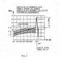
- the counteracting torque of the lever 1 opposing the action exerted by the driver has, for example, the profile shown in figure 2 .
- Figure 2 shows the profile of the counteracting torque exerted by the engagement lever of the parking brake. It can be seen that such counteracting torque profile, expressed in Nm, has a peak at a third angle of rotation C of the lever, intermediate between A and B, for example fixed at 67°. The counteracting torque decreases quickly between the portion C corresponding to the third angle of rotation, and the position B placed for example at 73°.
- the vent valve of the pneumatic circuit begins opening. Consequently, the vent valve is fully opened at or immediately before the position B of the lever 1.
- the rotation of the lever 1 occurs on a plane parallel to the longitudinal development of the vehicle, namely parallel to the travelling direction.
- vent valve of the pneumatic circuit Since the vent valve of the pneumatic circuit is at least partially open, even though not completely, in the space of some fractions of a second the pressure within the pneumatic circuit drops until it provokes the turning on of the warning lights in the dashboard and the clamping of the brakes, as stated in the technical regulations of the field.
- a further signalling is given when the driver's door opens and the lever 1 is not in the engagement position B of the parking brakes, which substantially corresponds to the end of stroke of the lever.
- a sensor 3 is placed on the lever itself 1 or on the support 2, so that it detects the end of stroke of the lever, namely the reaching of the position B.
- Such sensor may be of any type: microswitch sensor, capacitive sensor, resistive sensor, etc..
- a switch/sensor (not shown in the figures), may be placed also in the driver's door.
- a buzzer and/or a warning light may be provided.
- the senor in the driver's door is already present in a vehicle, as well as the buzzer, thus the present invention may be implemented without any massive intervention on the onboard components.
- Such sensors/switches and such buzzer/warning light may be connected to processing means (not shown in the figures) or to a vehicular control unit already present in the vehicle and appropriately configured to perform the control method according to what is described below.
- Figure 3 shows a flowchart wherein, at steps 12 and 13, a control on the condition "open door” (verification of condition alpha) and on the condition “lever 1 NOT in position B” (verification of condition beta) is performed. If both conditions are verified (step 14), then a signalling, preferably acoustic, is given (step 15), otherwise such signalling is inhibited and the method is iteratively restarted from the beginning (start, step 11).
- a signalling preferably acoustic
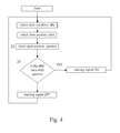
- figure 4 such signalling is given when the gear is also in neutral (verification of condition gamma).
- step of the acquisition of the condition of the gear has been added and the control (step 24) has been updated adding in AND also the verification of such further condition together with the ones previously considered.
- such signalling is given when the gear is in neutral and neither the accelerator pedal, nor the clutch pedal, not the brake pedal are pressed.
- Such conditions may be considered separately or together.
- delta indicates an overall condition wherein all the aforementioned conditions are verified:
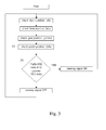
- Figure 5 shows a flowchart integrating such further details. Also in this case, only the new or varied blocks have been numbered, the others being left unchanged compared to figure 4 .
- step 33 the aforementioned condition delta (step 33) is further checked, and if it is verified (step 34), the aforementioned signalling is activated (step 15).
- the alternative embodiments of the method for controlling the signalling system are independent from the operating conditions of the engine, since the air in the accumulation tank is usually sufficient to open the brakes, even when the engine is stopped.
- the present invention may advantageously be realized by means of a computer program, which comprises program code means performing one or more steps of said method, when said program is run on a computer.
- program code means performing one or more steps of said method
- the scope of the present patent is meant to cover also said computer program and the computer-readable means that comprise a recorded message, such computer-readable means comprising the program code means for performing one or more steps of such method, when such program is run on a computer.
- the present invention allows to overcome the problems of unstableness of the pneumatic circuits controlling the brakes, avoiding dangerous situations wherein the brake may be disengaged when the driver is outside the vehicle.
Landscapes
- Engineering & Computer Science (AREA)
- Transportation (AREA)
- Mechanical Engineering (AREA)
- Regulating Braking Force (AREA)
Abstract
Description
- The present invention refers to the field of the systems for controlling the engagement of the parking brake in vehicles having the brakes controlled by a pneumatic circuit, especially heavy vehicles.
-
WO2007043957 shows an acoustic signalling system addressed to the vehicle's driver when the following conditions are verified: - A) engine is started,
- B) driver's door is open,
- C) neither the accelerator pedal, nor the clutch pedal, nor the brake pedal are pressed
- D) gear is in neutral,
- E) the parking brake is not engaged.
- It is important to add further details on the meaning of the characteristic D).
- Paragraph [0013] specifies that the parking brake is engaged when the pressure in the pneumatic circuit controlling the brakes is below a certain level.
- Indeed, according to the technical regulations ECE R13, a warning light in the dashboard is turned on depending on the pressure level reached in the pneumatic circuit controlling the brakes. In particular, the warning light turns on to signal the engagement of the parking brake only when the pressure is below a predetermined value.
WO2007043957 , in paragraph [0021], specifies that heavy vehicles in conformity with the aforementioned regulations, are in themselves equipped with a signalling system and thus any further signalling is inhibited. - Such method for managing the additional signalling can be improved in terms of safety.
- Therefore, the aim of the present invention is to improve the safety of the signalling systems known in the art.
- The object of the present invention is to provide a system for controlling the engagement of the parking brake in a pneumatic braking system, according to
claim 1. - According to the present invention, the system for controlling the engagement of the parking brake is applied to the braking systems of the pneumatic type, in particular of heavy vehicles. Such pneumatic braking systems comprise a lever that can rotate around a respective fulcrum between a first release position and a second engagement position of the parking brake. The lever controls a vent valve of the braking system, so that it is fully open at least in said second engagement position. In an intermediate position between said two positions of the lever, a counteracting torque is present opposing the commutation of the lever. The control system according to the present invention comprises means for detecting an open condition of a driver's door (alpha), means for detecting the position of said lever and signalling means, activated when said door is open and said lever is not in said second position.
- A particular object of the present invention is a method for controlling the engagement of the parking brake in a pneumatic braking system, as described more fully in the claims, which are an integral part of the present description.
- Further purposes and advantages of the present invention will become clear from the following detailed description of a preferred embodiment (and its alternative embodiments) and the drawings that are attached hereto, which are merely illustrative and non-limitative, in which:
-
figure 1 shows an engagement lever of a parking brake, -
figure 2 shows a diagram of a counteracting torque profile of the lever offigure 1 when it rotates with respect to a respective fulcrum; - figures from 3 to 5 show examples of flowcharts illustrating alternative embodiments of control methods according to the present invention.
- In the figures the same reference numbers and letters identify the same elements or components.
-
Figure 1 shows anengagement lever 1 of the parking brake of a vehicle having a pneumatic braking system, which is typical, but not exclusive, of heavy vehicles. Thelever 1 is constrained to asupport element 2 defining a fulcrum, with respect to which it can be moved from a fully released position A of the parking brake (leftward rotation in the figure) and an engagement position B of the parking brake (rightward rotation in the figure), thelever 1 being shown in this position by a dotted line. - A first angle of rotation of 0°, for example, is associated to the fully released position of the parking brake.
- During the rotation of the
lever 1 towards the engagement position B of the parking brake, the counteracting torque of thelever 1 opposing the action exerted by the driver has, for example, the profile shown infigure 2 . -
Figure 2 shows the profile of the counteracting torque exerted by the engagement lever of the parking brake. It can be seen that such counteracting torque profile, expressed in Nm, has a peak at a third angle of rotation C of the lever, intermediate between A and B, for example fixed at 67°. The counteracting torque decreases quickly between the portion C corresponding to the third angle of rotation, and the position B placed for example at 73°. - At the position C of the
lever 1, or immediately before, the vent valve of the pneumatic circuit begins opening. Consequently, the vent valve is fully opened at or immediately before the position B of thelever 1. - In general, the rotation of the
lever 1 occurs on a plane parallel to the longitudinal development of the vehicle, namely parallel to the travelling direction. - Such specific counteracting torque profile has been adopted in order to prevent a movement the lever to the position A due to an accidental actuation of the
lever 1 or due to the force of gravity acting on the lever itself, when the vehicle is parked uphill (or downhill). - Consider also that, when the vehicle is left with the engine started, the vibrations propagating from the internal combustion engine to the whole cabin may be remarkable, facilitating the disengagement of the parking brake.
- Thus, such counteracting torque profile of the lever of the parking brake contributes to the safety of the vehicle.
- If the driver inadvertently moves the
lever 1 exactly in position C, such position of thelever 1 is unstable. - Since the vent valve of the pneumatic circuit is at least partially open, even though not completely, in the space of some fractions of a second the pressure within the pneumatic circuit drops until it provokes the turning on of the warning lights in the dashboard and the clamping of the brakes, as stated in the technical regulations of the field.
- According to the present invention, a further signalling is given when the driver's door opens and the
lever 1 is not in the engagement position B of the parking brakes, which substantially corresponds to the end of stroke of the lever. - To this end, a
sensor 3 is placed on the lever itself 1 or on thesupport 2, so that it detects the end of stroke of the lever, namely the reaching of the position B. - Such sensor may be of any type: microswitch sensor, capacitive sensor, resistive sensor, etc..
- A switch/sensor (not shown in the figures), may be placed also in the driver's door.
- Furthermore, a buzzer and/or a warning light, for example additional, may be provided.
- In general, the sensor in the driver's door is already present in a vehicle, as well as the buzzer, thus the present invention may be implemented without any massive intervention on the onboard components.
- Such sensors/switches and such buzzer/warning light may be connected to processing means (not shown in the figures) or to a vehicular control unit already present in the vehicle and appropriately configured to perform the control method according to what is described below.
-
Figure 3 shows a flowchart wherein, atsteps - According to a preferred alternative embodiment of the invention,
figure 4 , such signalling is given when the gear is also in neutral (verification of condition gamma). - In
figure 4 , only the new or varied blocks compared tofigure 3 are indicated by numbers, the others being left unchanged. - In particular, the step of the acquisition of the condition of the gear (step 23) has been added and the control (step 24) has been updated adding in AND also the verification of such further condition together with the ones previously considered.
- According to a further alternative embodiment of the invention, such signalling is given when the gear is in neutral and neither the accelerator pedal, nor the clutch pedal, not the brake pedal are pressed. Such conditions may be considered separately or together. For convenience, delta indicates an overall condition wherein all the aforementioned conditions are verified:
- the accelerator pedal is not pressed, namely it is released,
- the clutch pedal is not pressed, namely it is released,
- the service brake pedal is not pressed, namely it is released.
-
Figure 5 shows a flowchart integrating such further details. Also in this case, only the new or varied blocks have been numbered, the others being left unchanged compared tofigure 4 . - In particular the aforementioned condition delta (step 33) is further checked, and if it is verified (step 34), the aforementioned signalling is activated (step 15).
- In general, the alternative embodiments of the method for controlling the signalling system are independent from the operating conditions of the engine, since the air in the accumulation tank is usually sufficient to open the brakes, even when the engine is stopped.
- The present invention may advantageously be realized by means of a computer program, which comprises program code means performing one or more steps of said method, when said program is run on a computer. For this reason the scope of the present patent is meant to cover also said computer program and the computer-readable means that comprise a recorded message, such computer-readable means comprising the program code means for performing one or more steps of such method, when such program is run on a computer.
- It will be apparent to the person skilled in the art that other alternative and equivalent embodiments of the invention can be conceived and reduced to practice without departing from the scope of the invention.
- The advantages deriving from the use of this invention are evident.
- It is evident that the present invention allows to overcome the problems of unstableness of the pneumatic circuits controlling the brakes, avoiding dangerous situations wherein the brake may be disengaged when the driver is outside the vehicle.
- From the description set forth above it will be possible for the person skilled in the art to embody the invention with no need of describing further construction details. The elements and the characteristics described in the different preferred embodiments may be combined without departing from the scope of the present application.
Claims (9)
- System for controlling the engagement of the parking brake in a pneumatic braking system, the braking system comprising a lever (1) that can be rotated around a respective fulcrum (2) between a first release position (A) and a second predetermined engagement position (B) of the parking brake, the lever (1) controlling a vent valve of the braking system, so that it is fully open at least in said second engagement position (B); at least in an intermediate position (C) of the lever, between said two positions (A, B), a counteracting torque is present opposing to the commutation of the lever (1), the control system comprising- means for detecting an open condition of a driver's door (alpha),- means for detecting at least one condition wherein said parking brake engagement lever (1) is not in said predetermined engagement position (B) of the parking brake (beta),- signalling means, activated when said door is open and said lever (1) is not in said second position (B).
- System according to claim 1, further comprising means for detecting a gear neutral condition (condition gamma), and wherein said signalling means are activated when also said gear neutral condition is verified.
- System according to claim 2, further comprising at least one of the following- means for detecting a release condition (i) of an accelerator pedal,- means for detecting at least a release condition (ii) of a clutch pedal,- means for detecting at least a release condition (iii) of a service brake pedal,
and wherein said signalling means are activated when also at least one of said release conditions (i - iii) is verified. - System according to any of the previous claims, further comprising processing means electrically connected with said detecting means and said signalling means in order to command such signalling means in relation to the conditions (alpha, beta, gamma) detected by the detecting means themselves.
- Method for controlling the engagement of the parking brake in a pneumatic braking system comprising the following steps:- detecting an open condition of a driver's door (alpha),- detecting a condition wherein a parking brake engagement lever (1) is not in a predetermined engagement position (B) of the parking brake (beta),- activation of the signalling means when both the previous conditions (alpha, beta) are verified.
- Method according to claim 5, further comprising the step of detecting a condition of gear in neutral (gamma), and wherein said activation of the signalling means is commanded when also said condition of neutral gear is verified.
- Method according to claim 6, further comprising the step of detecting at least one of the following conditions:- release (i) of the accelerator pedal,- release (ii) of the clutch pedal,- release (iii) of the service brake pedal,
and wherein said activation of the signalling means is commanded when also at least one of the release conditions (i - iii) is verified. - Computer program comprising program code means suitable for performing the steps of any claim from 5 to 7, when such program is run on a computer.
- Computer-readable means comprising a recorded program, said computer-readable means comprising program code means suitable for performing the steps according to the claims from 5 to 7, when said program is run on a computer.
Priority Applications (2)
| Application Number | Priority Date | Filing Date | Title |
|---|---|---|---|
| EP12168406.2A EP2664505B1 (en) | 2012-05-17 | 2012-05-17 | System for controlling the engagement of a parking brake in a pneumatic braking system |
| ES12168406T ES2706427T3 (en) | 2012-05-17 | 2012-05-17 | System to control the coupling of a parking brake in a pneumatic braking system |
Applications Claiming Priority (1)
| Application Number | Priority Date | Filing Date | Title |
|---|---|---|---|
| EP12168406.2A EP2664505B1 (en) | 2012-05-17 | 2012-05-17 | System for controlling the engagement of a parking brake in a pneumatic braking system |
Publications (2)
| Publication Number | Publication Date |
|---|---|
| EP2664505A1 true EP2664505A1 (en) | 2013-11-20 |
| EP2664505B1 EP2664505B1 (en) | 2018-11-21 |
Family
ID=46581716
Family Applications (1)
| Application Number | Title | Priority Date | Filing Date |
|---|---|---|---|
| EP12168406.2A Active EP2664505B1 (en) | 2012-05-17 | 2012-05-17 | System for controlling the engagement of a parking brake in a pneumatic braking system |
Country Status (2)
| Country | Link |
|---|---|
| EP (1) | EP2664505B1 (en) |
| ES (1) | ES2706427T3 (en) |
Cited By (1)
| Publication number | Priority date | Publication date | Assignee | Title |
|---|---|---|---|---|
| US20240092323A1 (en) * | 2022-09-12 | 2024-03-21 | Bendix Commercial Vehicle Systems Llc | System and Method for Preventing Vehicle Roll-Away |
Citations (6)
| Publication number | Priority date | Publication date | Assignee | Title |
|---|---|---|---|---|
| GB1526573A (en) * | 1976-04-02 | 1978-09-27 | Chrysler Uk | Vehicle warning light systems |
| WO2000015480A2 (en) * | 1998-07-01 | 2000-03-23 | Dale Maslonka | Automatic air parking brake lock and method |
| US20020189882A1 (en) * | 2001-06-13 | 2002-12-19 | Honeywell Commercial Vehicle Systems Company | School bus door/service brake interlock retrofit system |
| WO2007043957A1 (en) | 2005-10-11 | 2007-04-19 | Scania Cv Ab (Publ) | Warning system |
| DE102010002507A1 (en) * | 2010-03-02 | 2011-09-08 | Robert Bosch Gmbh | Method for automatic operation of brake device of cabriolet car during reverse movement, involves operating brake device in dependence of state of door such that door in opening state and motor vehicle are automatically braked at same time |
| GB2478771A (en) * | 2010-03-18 | 2011-09-21 | Pownall Security Systems Ltd | Warning installation for air spring park brake systems |
-
2012
- 2012-05-17 EP EP12168406.2A patent/EP2664505B1/en active Active
- 2012-05-17 ES ES12168406T patent/ES2706427T3/en active Active
Patent Citations (6)
| Publication number | Priority date | Publication date | Assignee | Title |
|---|---|---|---|---|
| GB1526573A (en) * | 1976-04-02 | 1978-09-27 | Chrysler Uk | Vehicle warning light systems |
| WO2000015480A2 (en) * | 1998-07-01 | 2000-03-23 | Dale Maslonka | Automatic air parking brake lock and method |
| US20020189882A1 (en) * | 2001-06-13 | 2002-12-19 | Honeywell Commercial Vehicle Systems Company | School bus door/service brake interlock retrofit system |
| WO2007043957A1 (en) | 2005-10-11 | 2007-04-19 | Scania Cv Ab (Publ) | Warning system |
| DE102010002507A1 (en) * | 2010-03-02 | 2011-09-08 | Robert Bosch Gmbh | Method for automatic operation of brake device of cabriolet car during reverse movement, involves operating brake device in dependence of state of door such that door in opening state and motor vehicle are automatically braked at same time |
| GB2478771A (en) * | 2010-03-18 | 2011-09-21 | Pownall Security Systems Ltd | Warning installation for air spring park brake systems |
Cited By (2)
| Publication number | Priority date | Publication date | Assignee | Title |
|---|---|---|---|---|
| US20240092323A1 (en) * | 2022-09-12 | 2024-03-21 | Bendix Commercial Vehicle Systems Llc | System and Method for Preventing Vehicle Roll-Away |
| US12179730B2 (en) * | 2022-09-12 | 2024-12-31 | Bendix Commercial Vehicle Systems Llc | System and method for preventing vehicle roll-away |
Also Published As
| Publication number | Publication date |
|---|---|
| EP2664505B1 (en) | 2018-11-21 |
| ES2706427T3 (en) | 2019-03-28 |
Similar Documents
| Publication | Publication Date | Title |
|---|---|---|
| US8044788B2 (en) | Warning system generating warning of disengagement of parking brake of motor vehicle | |
| US7338137B2 (en) | Method and system for assisting the driveaway of a motor vehicle | |
| US10486660B2 (en) | Method and apparatus for operating an electromotive parking brake of a motor vehicle, and motor vehicle | |
| EP1849667B1 (en) | Electric park brake system | |
| EP2483113B1 (en) | Electronically controlled park brake system | |
| JP5279955B2 (en) | How to activate an electronic parking brake system | |
| US20120245816A1 (en) | Method for reducing the clamping force applied by a parking brake | |
| US6384490B1 (en) | Process when starting the engine of a vehicle | |
| US11105273B2 (en) | System and method for automatically controlling an exhaust brake of a vehicle | |
| JP2010143542A (en) | Electric parking brake system | |
| CN104179828B (en) | For performing the method for the reference operation of the electrically-energized clutch system of energy and corresponding clutch system | |
| CN102612455A (en) | Method for preventing a vehicle from rolling away, and computer program product | |
| CN105835862A (en) | A control method, device and system for vehicle anti-slide slope | |
| EP2664505B1 (en) | System for controlling the engagement of a parking brake in a pneumatic braking system | |
| EP3369914B1 (en) | Information providing method for vehicle and information providing device for vehicle | |
| US20080147286A1 (en) | Control System for the Parking Brake of a Brake System in a Motor Vehicle | |
| CN103029692B (en) | For method, brakes and the vehicle of decelerating vehicles | |
| KR101535355B1 (en) | Emergency brake system for vehicle | |
| KR102383249B1 (en) | Auto braking control method and vehicle which the method is applied to | |
| US10493960B2 (en) | Method for operating at least one parking brake of a motor vehicle | |
| JP2013505877A (en) | How to deactivate the electronic parking brake system | |
| JP2006335314A (en) | Braking control device | |
| CA2803203C (en) | Vehicle safety apparatus | |
| JP4164096B2 (en) | Vehicle control system | |
| EP2072333B1 (en) | Method and device for controlling the signalling of the intervention of the electric parking brake of a vehicle |
Legal Events
| Date | Code | Title | Description |
|---|---|---|---|
| PUAI | Public reference made under article 153(3) epc to a published international application that has entered the european phase |
Free format text: ORIGINAL CODE: 0009012 |
|
| AK | Designated contracting states |
Kind code of ref document: A1 Designated state(s): AL AT BE BG CH CY CZ DE DK EE ES FI FR GB GR HR HU IE IS IT LI LT LU LV MC MK MT NL NO PL PT RO RS SE SI SK SM TR |
|
| AX | Request for extension of the european patent |
Extension state: BA ME |
|
| 17P | Request for examination filed |
Effective date: 20140519 |
|
| RBV | Designated contracting states (corrected) |
Designated state(s): AL AT BE BG CH CY CZ DE DK EE ES FI FR GB GR HR HU IE IS IT LI LT LU LV MC MK MT NL NO PL PT RO RS SE SI SK SM TR |
|
| GRAP | Despatch of communication of intention to grant a patent |
Free format text: ORIGINAL CODE: EPIDOSNIGR1 |
|
| STAA | Information on the status of an ep patent application or granted ep patent |
Free format text: STATUS: GRANT OF PATENT IS INTENDED |
|
| RIC1 | Information provided on ipc code assigned before grant |
Ipc: B60T 17/18 20060101ALI20180606BHEP Ipc: B60T 15/04 20060101ALI20180606BHEP Ipc: B60T 17/22 20060101ALI20180606BHEP Ipc: B60T 7/14 20060101AFI20180606BHEP Ipc: B60T 7/08 20060101ALI20180606BHEP |
|
| INTG | Intention to grant announced |
Effective date: 20180629 |
|
| GRAS | Grant fee paid |
Free format text: ORIGINAL CODE: EPIDOSNIGR3 |
|
| GRAA | (expected) grant |
Free format text: ORIGINAL CODE: 0009210 |
|
| STAA | Information on the status of an ep patent application or granted ep patent |
Free format text: STATUS: THE PATENT HAS BEEN GRANTED |
|
| AK | Designated contracting states |
Kind code of ref document: B1 Designated state(s): AL AT BE BG CH CY CZ DE DK EE ES FI FR GB GR HR HU IE IS IT LI LT LU LV MC MK MT NL NO PL PT RO RS SE SI SK SM TR |
|
| REG | Reference to a national code |
Ref country code: CH Ref legal event code: EP |
|
| REG | Reference to a national code |
Ref country code: IE Ref legal event code: FG4D |
|
| REG | Reference to a national code |
Ref country code: DE Ref legal event code: R096 Ref document number: 602012053705 Country of ref document: DE |
|
| REG | Reference to a national code |
Ref country code: AT Ref legal event code: REF Ref document number: 1067180 Country of ref document: AT Kind code of ref document: T Effective date: 20181215 |
|
| REG | Reference to a national code |
Ref country code: NL Ref legal event code: FP |
|
| REG | Reference to a national code |
Ref country code: SE Ref legal event code: TRGR |
|
| REG | Reference to a national code |
Ref country code: ES Ref legal event code: FG2A Ref document number: 2706427 Country of ref document: ES Kind code of ref document: T3 Effective date: 20190328 |
|
| REG | Reference to a national code |
Ref country code: AT Ref legal event code: MK05 Ref document number: 1067180 Country of ref document: AT Kind code of ref document: T Effective date: 20181121 |
|
| PG25 | Lapsed in a contracting state [announced via postgrant information from national office to epo] |
Ref country code: LV Free format text: LAPSE BECAUSE OF FAILURE TO SUBMIT A TRANSLATION OF THE DESCRIPTION OR TO PAY THE FEE WITHIN THE PRESCRIBED TIME-LIMIT Effective date: 20181121 Ref country code: AT Free format text: LAPSE BECAUSE OF FAILURE TO SUBMIT A TRANSLATION OF THE DESCRIPTION OR TO PAY THE FEE WITHIN THE PRESCRIBED TIME-LIMIT Effective date: 20181121 Ref country code: FI Free format text: LAPSE BECAUSE OF FAILURE TO SUBMIT A TRANSLATION OF THE DESCRIPTION OR TO PAY THE FEE WITHIN THE PRESCRIBED TIME-LIMIT Effective date: 20181121 Ref country code: NO Free format text: LAPSE BECAUSE OF FAILURE TO SUBMIT A TRANSLATION OF THE DESCRIPTION OR TO PAY THE FEE WITHIN THE PRESCRIBED TIME-LIMIT Effective date: 20190221 Ref country code: IS Free format text: LAPSE BECAUSE OF FAILURE TO SUBMIT A TRANSLATION OF THE DESCRIPTION OR TO PAY THE FEE WITHIN THE PRESCRIBED TIME-LIMIT Effective date: 20190321 Ref country code: HR Free format text: LAPSE BECAUSE OF FAILURE TO SUBMIT A TRANSLATION OF THE DESCRIPTION OR TO PAY THE FEE WITHIN THE PRESCRIBED TIME-LIMIT Effective date: 20181121 Ref country code: LT Free format text: LAPSE BECAUSE OF FAILURE TO SUBMIT A TRANSLATION OF THE DESCRIPTION OR TO PAY THE FEE WITHIN THE PRESCRIBED TIME-LIMIT Effective date: 20181121 Ref country code: BG Free format text: LAPSE BECAUSE OF FAILURE TO SUBMIT A TRANSLATION OF THE DESCRIPTION OR TO PAY THE FEE WITHIN THE PRESCRIBED TIME-LIMIT Effective date: 20190221 |
|
| PG25 | Lapsed in a contracting state [announced via postgrant information from national office to epo] |
Ref country code: GR Free format text: LAPSE BECAUSE OF FAILURE TO SUBMIT A TRANSLATION OF THE DESCRIPTION OR TO PAY THE FEE WITHIN THE PRESCRIBED TIME-LIMIT Effective date: 20190222 Ref country code: PT Free format text: LAPSE BECAUSE OF FAILURE TO SUBMIT A TRANSLATION OF THE DESCRIPTION OR TO PAY THE FEE WITHIN THE PRESCRIBED TIME-LIMIT Effective date: 20190321 Ref country code: AL Free format text: LAPSE BECAUSE OF FAILURE TO SUBMIT A TRANSLATION OF THE DESCRIPTION OR TO PAY THE FEE WITHIN THE PRESCRIBED TIME-LIMIT Effective date: 20181121 Ref country code: RS Free format text: LAPSE BECAUSE OF FAILURE TO SUBMIT A TRANSLATION OF THE DESCRIPTION OR TO PAY THE FEE WITHIN THE PRESCRIBED TIME-LIMIT Effective date: 20181121 |
|
| PG25 | Lapsed in a contracting state [announced via postgrant information from national office to epo] |
Ref country code: CZ Free format text: LAPSE BECAUSE OF FAILURE TO SUBMIT A TRANSLATION OF THE DESCRIPTION OR TO PAY THE FEE WITHIN THE PRESCRIBED TIME-LIMIT Effective date: 20181121 Ref country code: PL Free format text: LAPSE BECAUSE OF FAILURE TO SUBMIT A TRANSLATION OF THE DESCRIPTION OR TO PAY THE FEE WITHIN THE PRESCRIBED TIME-LIMIT Effective date: 20181121 Ref country code: DK Free format text: LAPSE BECAUSE OF FAILURE TO SUBMIT A TRANSLATION OF THE DESCRIPTION OR TO PAY THE FEE WITHIN THE PRESCRIBED TIME-LIMIT Effective date: 20181121 |
|
| REG | Reference to a national code |
Ref country code: DE Ref legal event code: R097 Ref document number: 602012053705 Country of ref document: DE |
|
| PG25 | Lapsed in a contracting state [announced via postgrant information from national office to epo] |
Ref country code: SK Free format text: LAPSE BECAUSE OF FAILURE TO SUBMIT A TRANSLATION OF THE DESCRIPTION OR TO PAY THE FEE WITHIN THE PRESCRIBED TIME-LIMIT Effective date: 20181121 Ref country code: RO Free format text: LAPSE BECAUSE OF FAILURE TO SUBMIT A TRANSLATION OF THE DESCRIPTION OR TO PAY THE FEE WITHIN THE PRESCRIBED TIME-LIMIT Effective date: 20181121 Ref country code: EE Free format text: LAPSE BECAUSE OF FAILURE TO SUBMIT A TRANSLATION OF THE DESCRIPTION OR TO PAY THE FEE WITHIN THE PRESCRIBED TIME-LIMIT Effective date: 20181121 Ref country code: SM Free format text: LAPSE BECAUSE OF FAILURE TO SUBMIT A TRANSLATION OF THE DESCRIPTION OR TO PAY THE FEE WITHIN THE PRESCRIBED TIME-LIMIT Effective date: 20181121 |
|
| PLBE | No opposition filed within time limit |
Free format text: ORIGINAL CODE: 0009261 |
|
| STAA | Information on the status of an ep patent application or granted ep patent |
Free format text: STATUS: NO OPPOSITION FILED WITHIN TIME LIMIT |
|
| 26N | No opposition filed |
Effective date: 20190822 |
|
| PG25 | Lapsed in a contracting state [announced via postgrant information from national office to epo] |
Ref country code: SI Free format text: LAPSE BECAUSE OF FAILURE TO SUBMIT A TRANSLATION OF THE DESCRIPTION OR TO PAY THE FEE WITHIN THE PRESCRIBED TIME-LIMIT Effective date: 20181121 |
|
| REG | Reference to a national code |
Ref country code: CH Ref legal event code: PL |
|
| PG25 | Lapsed in a contracting state [announced via postgrant information from national office to epo] |
Ref country code: CH Free format text: LAPSE BECAUSE OF NON-PAYMENT OF DUE FEES Effective date: 20190531 Ref country code: MC Free format text: LAPSE BECAUSE OF FAILURE TO SUBMIT A TRANSLATION OF THE DESCRIPTION OR TO PAY THE FEE WITHIN THE PRESCRIBED TIME-LIMIT Effective date: 20181121 Ref country code: LI Free format text: LAPSE BECAUSE OF NON-PAYMENT OF DUE FEES Effective date: 20190531 |
|
| REG | Reference to a national code |
Ref country code: BE Ref legal event code: MM Effective date: 20190531 |
|
| PG25 | Lapsed in a contracting state [announced via postgrant information from national office to epo] |
Ref country code: LU Free format text: LAPSE BECAUSE OF NON-PAYMENT OF DUE FEES Effective date: 20190517 |
|
| PG25 | Lapsed in a contracting state [announced via postgrant information from national office to epo] |
Ref country code: TR Free format text: LAPSE BECAUSE OF FAILURE TO SUBMIT A TRANSLATION OF THE DESCRIPTION OR TO PAY THE FEE WITHIN THE PRESCRIBED TIME-LIMIT Effective date: 20181121 |
|
| PG25 | Lapsed in a contracting state [announced via postgrant information from national office to epo] |
Ref country code: IE Free format text: LAPSE BECAUSE OF NON-PAYMENT OF DUE FEES Effective date: 20190517 |
|
| PG25 | Lapsed in a contracting state [announced via postgrant information from national office to epo] |
Ref country code: BE Free format text: LAPSE BECAUSE OF NON-PAYMENT OF DUE FEES Effective date: 20190531 |
|
| PG25 | Lapsed in a contracting state [announced via postgrant information from national office to epo] |
Ref country code: CY Free format text: LAPSE BECAUSE OF FAILURE TO SUBMIT A TRANSLATION OF THE DESCRIPTION OR TO PAY THE FEE WITHIN THE PRESCRIBED TIME-LIMIT Effective date: 20181121 |
|
| PG25 | Lapsed in a contracting state [announced via postgrant information from national office to epo] |
Ref country code: HU Free format text: LAPSE BECAUSE OF FAILURE TO SUBMIT A TRANSLATION OF THE DESCRIPTION OR TO PAY THE FEE WITHIN THE PRESCRIBED TIME-LIMIT; INVALID AB INITIO Effective date: 20120517 Ref country code: MT Free format text: LAPSE BECAUSE OF FAILURE TO SUBMIT A TRANSLATION OF THE DESCRIPTION OR TO PAY THE FEE WITHIN THE PRESCRIBED TIME-LIMIT Effective date: 20181121 |
|
| PG25 | Lapsed in a contracting state [announced via postgrant information from national office to epo] |
Ref country code: MK Free format text: LAPSE BECAUSE OF FAILURE TO SUBMIT A TRANSLATION OF THE DESCRIPTION OR TO PAY THE FEE WITHIN THE PRESCRIBED TIME-LIMIT Effective date: 20181121 |
|
| P01 | Opt-out of the competence of the unified patent court (upc) registered |
Effective date: 20230523 |
|
| PGFP | Annual fee paid to national office [announced via postgrant information from national office to epo] |
Ref country code: SE Payment date: 20250228 Year of fee payment: 14 |
|
| PGFP | Annual fee paid to national office [announced via postgrant information from national office to epo] |
Ref country code: NL Payment date: 20250526 Year of fee payment: 14 |
|
| PGFP | Annual fee paid to national office [announced via postgrant information from national office to epo] |
Ref country code: DE Payment date: 20250528 Year of fee payment: 14 |
|
| PGFP | Annual fee paid to national office [announced via postgrant information from national office to epo] |
Ref country code: ES Payment date: 20250611 Year of fee payment: 14 |
|
| PGFP | Annual fee paid to national office [announced via postgrant information from national office to epo] |
Ref country code: IT Payment date: 20250512 Year of fee payment: 14 |
|
| PGFP | Annual fee paid to national office [announced via postgrant information from national office to epo] |
Ref country code: FR Payment date: 20250526 Year of fee payment: 14 |
|
| PGFP | Annual fee paid to national office [announced via postgrant information from national office to epo] |
Ref country code: GB Payment date: 20260304 Year of fee payment: 15 |