EP2664477A1 - Holding mechanism for display device and assembling method of the same - Google Patents
Holding mechanism for display device and assembling method of the same Download PDFInfo
- Publication number
- EP2664477A1 EP2664477A1 EP13167539.9A EP13167539A EP2664477A1 EP 2664477 A1 EP2664477 A1 EP 2664477A1 EP 13167539 A EP13167539 A EP 13167539A EP 2664477 A1 EP2664477 A1 EP 2664477A1
- Authority
- EP
- European Patent Office
- Prior art keywords
- display device
- thin plate
- elastic member
- front cover
- holding mechanism
- Prior art date
- Legal status (The legal status is an assumption and is not a legal conclusion. Google has not performed a legal analysis and makes no representation as to the accuracy of the status listed.)
- Granted
Links
Images



Classifications
-
- G—PHYSICS
- G06—COMPUTING OR CALCULATING; COUNTING
- G06F—ELECTRIC DIGITAL DATA PROCESSING
- G06F1/00—Details not covered by groups G06F3/00 - G06F13/00 and G06F21/00
- G06F1/16—Constructional details or arrangements
- G06F1/1601—Constructional details related to the housing of computer displays, e.g. of CRT monitors, of flat displays
-
- G—PHYSICS
- G02—OPTICS
- G02F—OPTICAL DEVICES OR ARRANGEMENTS FOR THE CONTROL OF LIGHT BY MODIFICATION OF THE OPTICAL PROPERTIES OF THE MEDIA OF THE ELEMENTS INVOLVED THEREIN; NON-LINEAR OPTICS; FREQUENCY-CHANGING OF LIGHT; OPTICAL LOGIC ELEMENTS; OPTICAL ANALOGUE/DIGITAL CONVERTERS
- G02F1/00—Devices or arrangements for the control of the intensity, colour, phase, polarisation or direction of light arriving from an independent light source, e.g. switching, gating or modulating; Non-linear optics
- G02F1/01—Devices or arrangements for the control of the intensity, colour, phase, polarisation or direction of light arriving from an independent light source, e.g. switching, gating or modulating; Non-linear optics for the control of the intensity, phase, polarisation or colour
- G02F1/13—Devices or arrangements for the control of the intensity, colour, phase, polarisation or direction of light arriving from an independent light source, e.g. switching, gating or modulating; Non-linear optics for the control of the intensity, phase, polarisation or colour based on liquid crystals, e.g. single liquid crystal display cells
- G02F1/133—Constructional arrangements; Operation of liquid crystal cells; Circuit arrangements
- G02F1/1333—Constructional arrangements; Manufacturing methods
- G02F1/133308—Support structures for LCD panels, e.g. frames or bezels
-
- B—PERFORMING OPERATIONS; TRANSPORTING
- B60—VEHICLES IN GENERAL
- B60K—ARRANGEMENT OR MOUNTING OF PROPULSION UNITS OR OF TRANSMISSIONS IN VEHICLES; ARRANGEMENT OR MOUNTING OF PLURAL DIVERSE PRIME-MOVERS IN VEHICLES; AUXILIARY DRIVES FOR VEHICLES; INSTRUMENTATION OR DASHBOARDS FOR VEHICLES; ARRANGEMENTS IN CONNECTION WITH COOLING, AIR INTAKE, GAS EXHAUST OR FUEL SUPPLY OF PROPULSION UNITS IN VEHICLES
- B60K35/00—Instruments specially adapted for vehicles; Arrangement of instruments in or on vehicles
- B60K35/40—Instruments specially adapted for improving the visibility thereof to the user, e.g. fogging prevention or anti-reflection arrangements
- B60K35/425—Anti-reflection arrangements
-
- B—PERFORMING OPERATIONS; TRANSPORTING
- B60—VEHICLES IN GENERAL
- B60K—ARRANGEMENT OR MOUNTING OF PROPULSION UNITS OR OF TRANSMISSIONS IN VEHICLES; ARRANGEMENT OR MOUNTING OF PLURAL DIVERSE PRIME-MOVERS IN VEHICLES; AUXILIARY DRIVES FOR VEHICLES; INSTRUMENTATION OR DASHBOARDS FOR VEHICLES; ARRANGEMENTS IN CONNECTION WITH COOLING, AIR INTAKE, GAS EXHAUST OR FUEL SUPPLY OF PROPULSION UNITS IN VEHICLES
- B60K35/00—Instruments specially adapted for vehicles; Arrangement of instruments in or on vehicles
- B60K35/50—Instruments characterised by their means of attachment to or integration in the vehicle
-
- G—PHYSICS
- G04—HOROLOGY
- G04G—ELECTRONIC TIME-PIECES
- G04G17/00—Structural details; Housings
- G04G17/02—Component assemblies
- G04G17/04—Mounting of electronic components
- G04G17/045—Mounting of the display
-
- H—ELECTRICITY
- H05—ELECTRIC TECHNIQUES NOT OTHERWISE PROVIDED FOR
- H05K—PRINTED CIRCUITS; CASINGS OR CONSTRUCTIONAL DETAILS OF ELECTRIC APPARATUS; MANUFACTURE OF ASSEMBLAGES OF ELECTRICAL COMPONENTS
- H05K13/00—Apparatus or processes specially adapted for manufacturing or adjusting assemblages of electric components
-
- B—PERFORMING OPERATIONS; TRANSPORTING
- B60—VEHICLES IN GENERAL
- B60K—ARRANGEMENT OR MOUNTING OF PROPULSION UNITS OR OF TRANSMISSIONS IN VEHICLES; ARRANGEMENT OR MOUNTING OF PLURAL DIVERSE PRIME-MOVERS IN VEHICLES; AUXILIARY DRIVES FOR VEHICLES; INSTRUMENTATION OR DASHBOARDS FOR VEHICLES; ARRANGEMENTS IN CONNECTION WITH COOLING, AIR INTAKE, GAS EXHAUST OR FUEL SUPPLY OF PROPULSION UNITS IN VEHICLES
- B60K2360/00—Indexing scheme associated with groups B60K35/00 or B60K37/00 relating to details of instruments or dashboards
-
- B—PERFORMING OPERATIONS; TRANSPORTING
- B60—VEHICLES IN GENERAL
- B60K—ARRANGEMENT OR MOUNTING OF PROPULSION UNITS OR OF TRANSMISSIONS IN VEHICLES; ARRANGEMENT OR MOUNTING OF PLURAL DIVERSE PRIME-MOVERS IN VEHICLES; AUXILIARY DRIVES FOR VEHICLES; INSTRUMENTATION OR DASHBOARDS FOR VEHICLES; ARRANGEMENTS IN CONNECTION WITH COOLING, AIR INTAKE, GAS EXHAUST OR FUEL SUPPLY OF PROPULSION UNITS IN VEHICLES
- B60K2360/00—Indexing scheme associated with groups B60K35/00 or B60K37/00 relating to details of instruments or dashboards
- B60K2360/60—Structural details of dashboards or instruments
- B60K2360/68—Features of instruments
- B60K2360/693—Cover plate features
-
- G—PHYSICS
- G02—OPTICS
- G02F—OPTICAL DEVICES OR ARRANGEMENTS FOR THE CONTROL OF LIGHT BY MODIFICATION OF THE OPTICAL PROPERTIES OF THE MEDIA OF THE ELEMENTS INVOLVED THEREIN; NON-LINEAR OPTICS; FREQUENCY-CHANGING OF LIGHT; OPTICAL LOGIC ELEMENTS; OPTICAL ANALOGUE/DIGITAL CONVERTERS
- G02F1/00—Devices or arrangements for the control of the intensity, colour, phase, polarisation or direction of light arriving from an independent light source, e.g. switching, gating or modulating; Non-linear optics
- G02F1/01—Devices or arrangements for the control of the intensity, colour, phase, polarisation or direction of light arriving from an independent light source, e.g. switching, gating or modulating; Non-linear optics for the control of the intensity, phase, polarisation or colour
- G02F1/13—Devices or arrangements for the control of the intensity, colour, phase, polarisation or direction of light arriving from an independent light source, e.g. switching, gating or modulating; Non-linear optics for the control of the intensity, phase, polarisation or colour based on liquid crystals, e.g. single liquid crystal display cells
- G02F1/133—Constructional arrangements; Operation of liquid crystal cells; Circuit arrangements
- G02F1/1333—Constructional arrangements; Manufacturing methods
- G02F1/133308—Support structures for LCD panels, e.g. frames or bezels
- G02F1/13332—Front frames
-
- G—PHYSICS
- G02—OPTICS
- G02F—OPTICAL DEVICES OR ARRANGEMENTS FOR THE CONTROL OF LIGHT BY MODIFICATION OF THE OPTICAL PROPERTIES OF THE MEDIA OF THE ELEMENTS INVOLVED THEREIN; NON-LINEAR OPTICS; FREQUENCY-CHANGING OF LIGHT; OPTICAL LOGIC ELEMENTS; OPTICAL ANALOGUE/DIGITAL CONVERTERS
- G02F2201/00—Constructional arrangements not provided for in groups G02F1/00 - G02F7/00
- G02F2201/50—Protective arrangements
- G02F2201/503—Arrangements improving the resistance to shock
-
- G—PHYSICS
- G02—OPTICS
- G02F—OPTICAL DEVICES OR ARRANGEMENTS FOR THE CONTROL OF LIGHT BY MODIFICATION OF THE OPTICAL PROPERTIES OF THE MEDIA OF THE ELEMENTS INVOLVED THEREIN; NON-LINEAR OPTICS; FREQUENCY-CHANGING OF LIGHT; OPTICAL LOGIC ELEMENTS; OPTICAL ANALOGUE/DIGITAL CONVERTERS
- G02F2201/00—Constructional arrangements not provided for in groups G02F1/00 - G02F7/00
- G02F2201/50—Protective arrangements
- G02F2201/505—Arrangements improving the resistance to acoustic resonance like noise
-
- Y—GENERAL TAGGING OF NEW TECHNOLOGICAL DEVELOPMENTS; GENERAL TAGGING OF CROSS-SECTIONAL TECHNOLOGIES SPANNING OVER SEVERAL SECTIONS OF THE IPC; TECHNICAL SUBJECTS COVERED BY FORMER USPC CROSS-REFERENCE ART COLLECTIONS [XRACs] AND DIGESTS
- Y10—TECHNICAL SUBJECTS COVERED BY FORMER USPC
- Y10T—TECHNICAL SUBJECTS COVERED BY FORMER US CLASSIFICATION
- Y10T29/00—Metal working
- Y10T29/49—Method of mechanical manufacture
- Y10T29/49002—Electrical device making
Definitions
- the present invention relates to a holding mechanism for a display device used for an indicator, a navigator and so on, and an assembling method of the holding mechanism for a display device.
- a vehicle such as an automobile has an instrument panel installed at a front portion in a vehicle interior.
- a controller of an air-conditioner is installed at the center in the width direction of the instrument panel. Some of these controllers of an air-conditioner have a display device.
- FIG.s 8 to 10 illustrate a controller 1 of an air-conditioner having a conventional display device.
- the controller 1 shown in FIG.s 8 to 10 includes a display device 2, a housing 3 containing the display device 2, and a front cover member 4 attached on a surface of the housing 3 so as to cover the display device 2.
- an elastic member 5 is interposed between a rim of the surface of the display device 2 and the front cover member 4.
- the elastic member 5 is made of a soft material such as urethane, and is adhesively attached to the surface of the display device 2.
- the elastic member 5 is interposed between the display device 2 and the front cover member 4 so that a gap is not generated between the display device 2 and the front cover member 4, any dust or foreign substance does not enter an inner side of the display device 2 and the front cover member 4.
- the display device 2 can forcibly be held by use of an elastic force of the elastic member 5.
- Patent Document 1 Japanese Utility Model Application Publication No. H03-100885
- the foregoing holding mechanism for the display device has a problem in that the elastic member 5 is difficult to handle in adhering on the surface of the display device 2, since the elastic member 5 is made of a soft material such as urethane and easily deformed.
- a holding mechanism for a display device includes a front cover member which is attached to a surface of a housing containing a display device so as to cover the display device, and a thin plate-like member having shape retention which is attached to an elastic member on a side facing the front cover member in a holding mechanism for the display device, wherein the elastic member is interposed between a rim of the display device and the front cover member, and the elastic member on which the thin plate-like member is adhered is attached to a reverse side of the front cover member.
- the following advantageous effects can be obtained. That is to say, since the thin plate-like member 21 having shape retention is attached to the elastic member on the side facing the front cover member, the elastic member becomes difficult to deform and easy to handle to adhere on the reverse side of the front cover member. Therefore, the incidence of a position gap is decreased when adhering the elastic member to the reverse side of the front cover member, and the need for re-adhering can be reduced. As a result, unsightly appearance by damage of the elastic member due to the re-adhering and an exposure of the glue side for adhering the elastic member can be prevented.
- the elastic member is homogeneously-squeezed over a wide range pressed through the thin plate-like member since it is pressed via the thin plate-like member when the front cover member is attached to a front side of the display device.
- protruding of the elastic member can be reduced.
- unsightly appearance due to the protruding part being visible externally can be prevented.
- the elastic member is homogeneously-squeezed via the thin plate-like member over a wide range, when the elastic member is held by a reinforcing rib provided to at least a part of the front cover member in order to make lighter the front cover member.
- the elastic member is prevented from being linearly-squeezed only at the part pressed by the reinforcing rib and its surrounding part is raised.
- the holding effect by an equable pressure can be obtained.
- the following functional effects will be obtained. That is to say, since the surface of the thin plate-like member having shape retention is antireflection-finished, the presence of the thin plate-like member can be unobtrusive externally. Further, it can be prevented that the reflected light from the thin plate-like member makes the display difficult to see and stands out in comparison with the display of the display device by the antireflection-finishing of the surface of the thin plate-like member.
- the thin plate-like member becomes easier to handle and its workability can be improved by making the thin plate-like member at least partly larger than the elastic member in shape. Further, the elastic member can be made less visible by the thin plate-like member.
- a vehicle such as an automobile has an instrument panel installed on an anterior part thereof.
- a controller of an air-conditioner is installed at the center in the width direction of the instrument panel. Some of these controllers of an air-conditioner have a display device.
- FIG.s 1 to 7 illustrate the embodiment and variations thereof.
- FTG.1 illustrates a controller 11 of an air-conditioner having a display device.
- the controller 11 includes a front cover member 14 attached to a surface of a housing 13 containing a display device 12 to cover the display device 12.
- an elastic member 15 is interposed between a rim of the display device 12 and the front cover member 14 as a basic configuration of a holding mechanism of the display device 12.
- a thin plate-like member 21 shown in FIG.1 will be described further below.
- the display device 12 is formed by, for example, a liquid crystal display, an organic electroluminescence display, and so on.
- the liquid crystal display includes a liquid crystal glass having a backlighting on its reverse side and covered entirely by a shielding member made of metal.
- the shielding member is attached to the rim of the surface of the display device 12 so as to form a frame-like part (frame-like member 12a).
- the housing 13 is made of, for example, resin.
- the housing 13 is configured to be a casing of the controller 11 of an air-conditioning system.
- a storing recess 13a for containing the display device 12 and attaching portions (not shown) for attaching the front cover member 14 are formed in the housing 13.
- the front cover member 14 is made of, for example, transparent resin.
- the front cover member 14 may be a lens form by varying its thickness or by curving its surface.
- the rim of the front cover member 14 can be painted a dark color with black paint or the like, or can be made of darkly-colored resin material.
- attaching portions 14b for attaching the front cover member 14 to the housing 13 are formed, for instance, on the corners of the front cover member 14.
- the elastic member 15 a material of urethane, sponge, gum, and so on, may be used.
- the elastic member 15 is assumed to be a frame shape surrounding the rim of the surface of the display device 12 (For instance, the frame-like member 12a).
- this embodiment has the further configurations described below.
- a thin plate-like member 21 having shape retention is attached to the elastic member 15 on a side facing the front cover member 14.
- shape retention means that a shape of the thin plate-like member 21 is not deformed even when the elastic member is compressed between the housing and the front cover member.
- the elastic member 15 attached to the thin plate-like member 21 is attached to an internal side (or reverse side) of the front cover member 14.
- the thin plate-like member 21 a resin plate, metal plate, and so on, may be used.
- the thin plate-like member 21 is assumed to be a resin plate.
- the thin plate-like member 21 is preferably a dark color such as black.
- the thin plate-like member 21 it is preferable that the thin plate-like member 21 have a thickness of approximately 0.3 mm to 1 mm in order to have shape retention. If the thin plate-like member 21 is thinner than 0.3 mm, it cannot maintain the shape retention. And, if the thin plate-like member 21 is thicker than 1 mm, it cannot be attached since the thin plate-like member 21 becomes thicker than the gap between the display device 12 and the front cover member 14.
- the thin plate-like member 21 is assumed to be a frame shape surrounding the rim of the surface of the display device 12 (for instance, the frame-like member 12a).
- a compound packing (a frame-shaped packing) is formed by the elastic member 15 attached to the thin plate-like member 21.
- an adhesive material 23 for attaching to the internal surface of the front cover member 14 is applied in advance.
- the adhesive material 23 can be partly or wholly applied to the surface of the thin plate-like member 21. In this case, the adhesive material 23 is applied to a position that is not visible externally when the front cover member 14 is mounted.
- the surface of the thin plate-like member 21 having shape retention is antireflection-finished (antireflective-finished part 24 shown in FIG.7 ).
- the antireflective finishing (the antireflective-finished part 24) can be a surface texturing, matte finish (fine concavo-convex processing), and so on.
- the thin plate-like member 21 having shape retention is made at least partly larger than the elastic member 15 in shape (slightly uneven part 25).
- a part (compound packing 22) consisting of the elastic member 15 and the thin plate-like member 21 is preferably produced by punching into a frame shape a compound sheet which is made of the elastic member 15 and the thin plate-like member 21 adhered together and integrated in advance.
- the compound packing 22 wherein the shape of the thin plate-like member 21 is slightly larger than the elastic member 15 can be obtained in a single process.
- the compound sheet shall be punched while compressing the whole part supposed to be the compound packing 22.
- the compound sheet shall be punched while compressing a part of the compound sheet.
- the display device 12 When assembling the controller 11, firstly, the display device 12 shall be stored in the housing 13 to be held.
- the elastic member 15 integrated with the thin plate-like member 21 shall be attached to the reverse side of the front cover member 14.
- the elastic member 15 shall be interposed between the rim of the display device 12 and the front cover member 14, and the display device 12 shall be held by a pressing force of the elastic member 15.
- the elastic member 15 becomes difficult to deform by attaching the thin plate-like member 21 having shape retention to the elastic member 15 on a side facing the front cover member 14 thereof. Therefore, the elastic member 15 becomes easy to handle and adhering to the reverse side of the front cover member 14 is made easier. Moreover, the incidence of a position gap is decreased when adhering the elastic member 15 to the reverse side of the front cover member 14, and the need for re-adhering can be reduced. As a result, unsightly appearance by damage of the elastic member 15 due to the re-adhering and exposure of the glue side for adhering the elastic member 15 can be prevented.
- protruding of the elastic member 15 can be reduced since the elastic member 15 is homogeneously-squeezed by the thin plate-like member 21 over a wide range.
- unsightly appearance can be prevented because a protruding part is not visible externally.
- the elastic member 15 is homogeneously-squeezed via the thin plate-like member 21 over a wide range, when the elastic member 15 is held by a reinforcing rib 14a provided to at least a part of the front cover member 14 in order to make lighter the front cover member 14.
- the elastic member 15 is prevented from being linearly-squeezed at only the part pressed by the reinforcing rib 14a and its surrounding part is raised.
- the holding effect by an equable pressure can be obtained.
- the thin plate-like member 21 can be unobtrusive externally by processing the antireflection-finish on the surface of the thin plate-like member 21 having shape retention. Further, it can be prevented that the reflected light from the thin plate-like member 21 makes the display difficult to see and stands out in comparison with the display of the display device 12 by the antireflection-finishing of the surface of the thin plate-like member 21.
- the thin plate-like member 21 becomes easy to handle and its workability can be improved by making the thin plate-like member 21 at least partly larger than the elastic member 15 in shape.
- the elastic member 15 can be made less visible by the thin plate-like member 21.
Landscapes
- Engineering & Computer Science (AREA)
- Physics & Mathematics (AREA)
- Chemical & Material Sciences (AREA)
- General Physics & Mathematics (AREA)
- Nonlinear Science (AREA)
- Combustion & Propulsion (AREA)
- Transportation (AREA)
- Mechanical Engineering (AREA)
- Theoretical Computer Science (AREA)
- General Engineering & Computer Science (AREA)
- Optics & Photonics (AREA)
- Crystallography & Structural Chemistry (AREA)
- Mathematical Physics (AREA)
- Manufacturing & Machinery (AREA)
- Microelectronics & Electronic Packaging (AREA)
- Computer Hardware Design (AREA)
- Human Computer Interaction (AREA)
- Devices For Indicating Variable Information By Combining Individual Elements (AREA)
- Fittings On The Vehicle Exterior For Carrying Loads, And Devices For Holding Or Mounting Articles (AREA)
- Vehicle Interior And Exterior Ornaments, Soundproofing, And Insulation (AREA)
Abstract
Description
- The present invention relates to a holding mechanism for a display device used for an indicator, a navigator and so on, and an assembling method of the holding mechanism for a display device.
- A vehicle such as an automobile has an instrument panel installed at a front portion in a vehicle interior. A controller of an air-conditioner is installed at the center in the width direction of the instrument panel. Some of these controllers of an air-conditioner have a display device.
-
FIG.s 8 to 10 illustrate acontroller 1 of an air-conditioner having a conventional display device.
Thecontroller 1 shown inFIG.s 8 to 10 includes adisplay device 2, ahousing 3 containing thedisplay device 2, and afront cover member 4 attached on a surface of thehousing 3 so as to cover thedisplay device 2. - Further, an
elastic member 5 is interposed between a rim of the surface of thedisplay device 2 and thefront cover member 4. - In this case, the
elastic member 5 is made of a soft material such as urethane, and is adhesively attached to the surface of thedisplay device 2. - Thus, since the
elastic member 5 is interposed between thedisplay device 2 and thefront cover member 4 so that a gap is not generated between thedisplay device 2 and thefront cover member 4, any dust or foreign substance does not enter an inner side of thedisplay device 2 and thefront cover member 4. - Moreover, an occurrence of noise caused by vibration and so on while the vehicle is moving can be prevented by avoiding direct contact of the
display device 2 with thefront cover member 4. - The
display device 2 can forcibly be held by use of an elastic force of theelastic member 5. - Note that, a structure similar to the above configuration is disclosed, for instance, in Japanese Utility Model Application Publication No.
H03-100885 - However, the foregoing holding mechanism for the display device has a problem in that the
elastic member 5 is difficult to handle in adhering on the surface of thedisplay device 2, since theelastic member 5 is made of a soft material such as urethane and easily deformed. - Thus, a position variation in a prescribed position is likely to occur when adhering the
elastic member 5 to the surface of thedisplay device 2, and sometimes extra work such as re-adhering and so on is required. - Moreover, there is a problem in that the appearance becomes unsightly since the
elastic member 5 is damaged by re-adhering, and the glue side on which theelastic member 5 is adhered becomes visible externally. - Further, as shown in
FIG. 11 , there is a problem in that the appearance becomes unsightly since a rim of theelastic member 5 is squeezed and protruded inward when thefront cover member 4 is attached to the front side of thedisplay device 2, and theprotruded part 6 is visible from outside. - In addition, as shown in
FIG. 12 , when a reinforcingrib 7 is provided to at least a part of thefront cover member 4 in order to lighten thefront cover member 4 and made to hold theelastic member 5, there is a problem in that theelastic member 5 is linearly-squeezed only at apart 8 pressed by the reinforcingrib 7 and its surrounding part is raised, accordingly, a holding effect by an equable pressure cannot be obtained. - In order to solve the above problems, a holding mechanism for a display device according to the present invention includes a front cover member which is attached to a surface of a housing containing a display device so as to cover the display device, and a thin plate-like member having shape retention which is attached to an elastic member on a side facing the front cover member in a holding mechanism for the display device, wherein the elastic member is interposed between a rim of the display device and the front cover member, and the elastic member on which the thin plate-like member is adhered is attached to a reverse side of the front cover member.
- According to foregoing configuration, the following advantageous effects can be obtained. That is to say, since the thin plate-
like member 21 having shape retention is attached to the elastic member on the side facing the front cover member, the elastic member becomes difficult to deform and easy to handle to adhere on the reverse side of the front cover member. Therefore, the incidence of a position gap is decreased when adhering the elastic member to the reverse side of the front cover member, and the need for re-adhering can be reduced. As a result, unsightly appearance by damage of the elastic member due to the re-adhering and an exposure of the glue side for adhering the elastic member can be prevented. - Further, the elastic member is homogeneously-squeezed over a wide range pressed through the thin plate-like member since it is pressed via the thin plate-like member when the front cover member is attached to a front side of the display device. As a result, protruding of the elastic member can be reduced. Thus, unsightly appearance due to the protruding part being visible externally can be prevented.
- In addition, the elastic member is homogeneously-squeezed via the thin plate-like member over a wide range, when the elastic member is held by a reinforcing rib provided to at least a part of the front cover member in order to make lighter the front cover member. As a result, the elastic member is prevented from being linearly-squeezed only at the part pressed by the reinforcing rib and its surrounding part is raised. Moreover, the holding effect by an equable pressure can be obtained.
- According to this invention described in another embodiment of the present invention, the following functional effects will be obtained. That is to say, since the surface of the thin plate-like member having shape retention is antireflection-finished, the presence of the thin plate-like member can be unobtrusive externally. Further, it can be prevented that the reflected light from the thin plate-like member makes the display difficult to see and stands out in comparison with the display of the display device by the antireflection-finishing of the surface of the thin plate-like member.
- According to this invention described in still another embodiment of the present invention, the following functional effects will be obtained. That is to say, the thin plate-like member becomes easier to handle and its workability can be improved by making the thin plate-like member at least partly larger than the elastic member in shape. Further, the elastic member can be made less visible by the thin plate-like member.
-
-
FIG.1 is an exploded perspective view of a holding mechanism for a display device according to an embodiment of the present invention; -
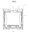
FIG.2 is a front view of FTG.1 in an assembled state; -
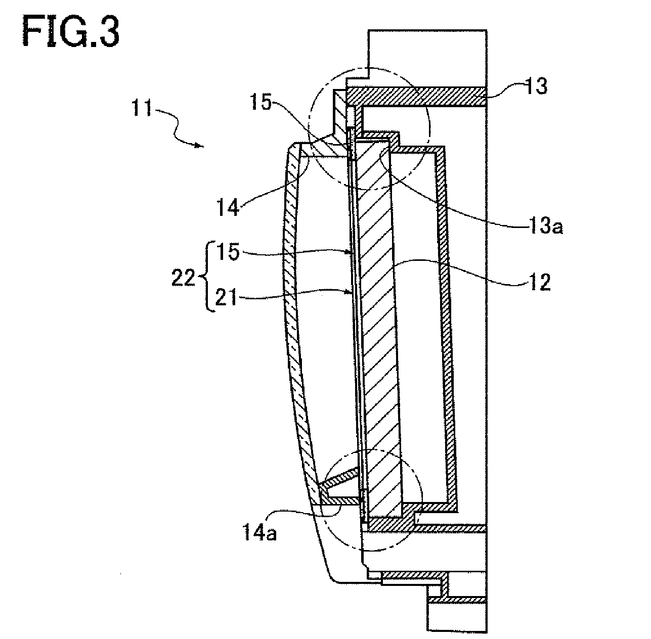
FIG.3 is a longitudinal sectional view ofFIG.2 along the center line; -
FIG.4 is an enlarged sectional view of an upper part ofFIG.3 ; -
FIG.5 is an enlarged sectional view of a lower part ofFIG.3 ; -
FIG.6 is a perspective view of the compound packing shown inFIG.1 ; -
FIG.7 is an enlarged side view ofFIG.6 ; -
FIG.8 is an exploded perspective view of a conventional holding mechanism for a display device; -
FIG.9 is a front view ofFIG.8 in an assembled state; -
FIG.10 is a longitudinal sectional view ofFIG.9 along a center line; -
FIG.11 is an enlarged sectional view of an upper part ofFIG.10 ; and -
FIG.12 is an enlarged sectional view of a lower part ofFIG.10 . - A vehicle such as an automobile has an instrument panel installed on an anterior part thereof. A controller of an air-conditioner is installed at the center in the width direction of the instrument panel. Some of these controllers of an air-conditioner have a display device.
- An embodiment of the present invention will be described hereinafter with reference to the drawings.
-
FIG.s 1 to 7 - Hereinafter, a configuration of the embodiment is described.
- FTG.1 illustrates a
controller 11 of an air-conditioner having a display device. - As shown in
FIG.1 (see alsoFIG.s 2 to 5 ), it is assumed that thecontroller 11 includes afront cover member 14 attached to a surface of ahousing 13 containing adisplay device 12 to cover thedisplay device 12. - Then, an
elastic member 15 is interposed between a rim of thedisplay device 12 and thefront cover member 14 as a basic configuration of a holding mechanism of thedisplay device 12. A thin plate-like member 21 shown inFIG.1 will be described further below. - Note that, "the
display device 12" is formed by, for example, a liquid crystal display, an organic electroluminescence display, and so on. The liquid crystal display includes a liquid crystal glass having a backlighting on its reverse side and covered entirely by a shielding member made of metal. The shielding member is attached to the rim of the surface of thedisplay device 12 so as to form a frame-like part (frame-like member 12a). - "The
housing 13" is made of, for example, resin. In this case, thehousing 13 is configured to be a casing of thecontroller 11 of an air-conditioning system. A storing recess 13a for containing thedisplay device 12 and attaching portions (not shown) for attaching thefront cover member 14 are formed in thehousing 13. - "The
front cover member 14" is made of, for example, transparent resin. Thefront cover member 14 may be a lens form by varying its thickness or by curving its surface. Moreover, the rim of thefront cover member 14 can be painted a dark color with black paint or the like, or can be made of darkly-colored resin material. Further, attachingportions 14b for attaching thefront cover member 14 to thehousing 13 are formed, for instance, on the corners of thefront cover member 14. - For "the
elastic member 15", a material of urethane, sponge, gum, and so on, may be used. Theelastic member 15 is assumed to be a frame shape surrounding the rim of the surface of the display device 12 (For instance, the frame-like member 12a). - Relative to the basic configuration above, this embodiment has the further configurations described below.
- As shown in
FIG.6 and FIG.7 , a thin plate-like member 21 having shape retention is attached to theelastic member 15 on a side facing thefront cover member 14. The term "shape retention" means that a shape of the thin plate-like member 21 is not deformed even when the elastic member is compressed between the housing and the front cover member.
Further, theelastic member 15 attached to the thin plate-like member 21 is attached to an internal side (or reverse side) of thefront cover member 14. - Note that, for "the thin plate-
like member 21" described above, a resin plate, metal plate, and so on, may be used. In this case, the thin plate-like member 21 is assumed to be a resin plate. The thin plate-like member 21 is preferably a dark color such as black. When the thin plate-like member 21 is assumed to be a resin plate, it is preferable that the thin plate-like member 21 have a thickness of approximately 0.3 mm to 1 mm in order to have shape retention. If the thin plate-like member 21 is thinner than 0.3 mm, it cannot maintain the shape retention. And, if the thin plate-like member 21 is thicker than 1 mm, it cannot be attached since the thin plate-like member 21 becomes thicker than the gap between thedisplay device 12 and thefront cover member 14. The thin plate-like member 21 is assumed to be a frame shape surrounding the rim of the surface of the display device 12 (for instance, the frame-like member 12a). - Then, a compound packing (a frame-shaped packing) is formed by the
elastic member 15 attached to the thin plate-like member 21. - On the obverse side of the thin plate-
like member 21, anadhesive material 23 for attaching to the internal surface of thefront cover member 14 is applied in advance. Theadhesive material 23 can be partly or wholly applied to the surface of the thin plate-like member 21. In this case, theadhesive material 23 is applied to a position that is not visible externally when thefront cover member 14 is mounted. - The surface of the thin plate-
like member 21 having shape retention is antireflection-finished (antireflective-finished part 24 shown inFIG.7 ). - Here, for instance the antireflective finishing (the antireflective-finished part 24) can be a surface texturing, matte finish (fine concavo-convex processing), and so on.
- The thin plate-
like member 21 having shape retention is made at least partly larger than theelastic member 15 in shape (slightly uneven part 25). - A part (compound packing 22) consisting of the
elastic member 15 and the thin plate-like member 21 is preferably produced by punching into a frame shape a compound sheet which is made of theelastic member 15 and the thin plate-like member 21 adhered together and integrated in advance. - Then, while the
elastic member 15 is kept inflated laterally by compressing the compound sheet with high pressure, the compound sheet is punched from the side of the thin plate-like member 21 and released from the pressure. Therefore, the compound packing 22 wherein the shape of the thin plate-like member 21 is slightly larger than theelastic member 15 can be obtained in a single process. - Note that, to obtain the compound packing 22 wherein the thin plate-
like member 21 is entirely larger than theelastic member 15, the compound sheet shall be punched while compressing the whole part supposed to be the compound packing 22. On the other hand, to obtain the compound packing 22 wherein the thin plate-like member 21 is partly larger than theelastic member 15, the compound sheet shall be punched while compressing a part of the compound sheet. - Hereinafter, a function of this embodiment will be described.
- When assembling the
controller 11, firstly, thedisplay device 12 shall be stored in thehousing 13 to be held. - On the other hand, the
elastic member 15 integrated with the thin plate-like member 21 shall be attached to the reverse side of thefront cover member 14. - Next, by attaching the
front cover member 14 to thehousing 13, theelastic member 15 shall be interposed between the rim of thedisplay device 12 and thefront cover member 14, and thedisplay device 12 shall be held by a pressing force of theelastic member 15. - According to this embodiment, the following effect will be obtained.
- The
elastic member 15 becomes difficult to deform by attaching the thin plate-like member 21 having shape retention to theelastic member 15 on a side facing thefront cover member 14 thereof. Therefore, theelastic member 15 becomes easy to handle and adhering to the reverse side of thefront cover member 14 is made easier. Moreover, the incidence of a position gap is decreased when adhering theelastic member 15 to the reverse side of thefront cover member 14, and the need for re-adhering can be reduced. As a result, unsightly appearance by damage of theelastic member 15 due to the re-adhering and exposure of the glue side for adhering theelastic member 15 can be prevented. - Further, as shown in
FIG.4 , protruding of theelastic member 15 can be reduced since theelastic member 15 is homogeneously-squeezed by the thin plate-like member 21 over a wide range. Thus, unsightly appearance can be prevented because a protruding part is not visible externally. - In addition, as shown in
FIG.5 , theelastic member 15 is homogeneously-squeezed via the thin plate-like member 21 over a wide range, when theelastic member 15 is held by a reinforcingrib 14a provided to at least a part of thefront cover member 14 in order to make lighter thefront cover member 14. As a result, theelastic member 15 is prevented from being linearly-squeezed at only the part pressed by the reinforcingrib 14a and its surrounding part is raised. Moreover, the holding effect by an equable pressure can be obtained. - The thin plate-
like member 21 can be unobtrusive externally by processing the antireflection-finish on the surface of the thin plate-like member 21 having shape retention. Further, it can be prevented that the reflected light from the thin plate-like member 21 makes the display difficult to see and stands out in comparison with the display of thedisplay device 12 by the antireflection-finishing of the surface of the thin plate-like member 21. - The thin plate-
like member 21 becomes easy to handle and its workability can be improved by making the thin plate-like member 21 at least partly larger than theelastic member 15 in shape. Theelastic member 15 can be made less visible by the thin plate-like member 21. - Hereinabove, an embodiment of this invention has been described in detail with reference to drawings. However, the embodiment is merely an exemplary illustration of this invention. Thus, this invention is not limited solely to the configuration in the embodiment and naturally includes design changes and the like without departing from the gist of this invention. Moreover, when an embodiment includes multiple configurations for example, this invention naturally includes possible combinations of these configurations even without specific descriptions thereof. Further, when multiple embodiments and/or multiple modifications are given, this invention naturally includes possible combinations of configurations within these even without specific descriptions thereof. Also, this invention naturally includes the configurations depicted in the drawings even without specific descriptions thereof. Furthermore, the wording "and/or the like," is used to mean that an equivalent is included.
Claims (10)
- A holding mechanism (11) for a display device (12) comprising:a housing (13) containing the display device;a front cover member (14) attached to a surface of the housing so as to cover the display device;an elastic member (15) interposed between a rim (12a) of the display device and the front cover member; anda thin plate-like member (21) having shape retention adhered to the elastic member on its side facing the front cover member,the elastic member on which the thin plate-like member is adhered being attached to an internal side of the front cover member.
- The holding mechanism for the display device according to Claim 1 wherein the thin plate-like member (21) is antireflection-finished.
- The holding mechanism for the display device according to Claim 1 wherein the thin plate-like member (21) is made at least partly larger than the elastic member (15) in shape.
- The holding mechanism for the display device according to Claim 1 wherein the thin plate-like member is antireflection-finished and made at least partly larger than the elastic member (15) in shape.
- An assembling method of a holding mechanism (11) for a display device (12) comprising:preparing a housing (13) containing a display device (12), a front cover member (14) to be attached to a surface of the housing to cover the display device, an elastic member (15) and a thin plate-like member (21) having shape retention;adhering the thin plate-like member (21) to a surface of the elastic member (15) facing the front cover member (14);making the elastic member and the thin plate-like member be adhered together into a frame shape, andattaching the elastic member to which the thin plate-like member is attached, to the front cover member.
- The assembling method of a holding mechanism for a display device according to Claim 5 comprising an antireflection-finishing process to a surface of the thin plate-like member (21).
- The assembling method of a holding mechanism for a display device according to Claim 5 wherein the thin plate-like member (21) is made at least partly larger than the elastic member (15) in shape.
- The assembling method of a holding mechanism for a display device according to Claim 5 wherein the thin plate-like member (21) is antireflection-finished and made at least partly larger than the elastic member (15) in shape.
- An assembling method of a holding mechanism (11) for a display device (12) having a housing (13) containing a display device, a front cover member (14) to be attached to a surface of the housing to cover the display device, an elastic member (15) and a thin plate-like member (21) having shape retention;
wherein the thin plate-like member is made at least partly larger than the elastic member in shape by:adhering together the elastic member and the thin plate-like member into a compound sheet (22) which is integrated;compressing the compound sheet with high pressure to keep the elastic member inflated laterally;punching the compound sheet into a frame shape; andreleasing the compound sheet from the pressure. - The assembling method of a holding mechanism for a display device according to Claim 9, further comprising an antireflection-finishing process to a surface of the thin plate-like member (21).
Applications Claiming Priority (1)
| Application Number | Priority Date | Filing Date | Title |
|---|---|---|---|
| JP2012110327A JP5890249B2 (en) | 2012-05-14 | 2012-05-14 | Display device holding structure |
Publications (2)
| Publication Number | Publication Date |
|---|---|
| EP2664477A1 true EP2664477A1 (en) | 2013-11-20 |
| EP2664477B1 EP2664477B1 (en) | 2016-02-10 |
Family
ID=48444125
Family Applications (1)
| Application Number | Title | Priority Date | Filing Date |
|---|---|---|---|
| EP13167539.9A Active EP2664477B1 (en) | 2012-05-14 | 2013-05-13 | Holding mechanism for display device and assembling method of the same |
Country Status (3)
| Country | Link |
|---|---|
| US (1) | US9081539B2 (en) |
| EP (1) | EP2664477B1 (en) |
| JP (1) | JP5890249B2 (en) |
Cited By (1)
| Publication number | Priority date | Publication date | Assignee | Title |
|---|---|---|---|---|
| DE102014201885A1 (en) * | 2014-02-03 | 2015-08-06 | Johnson Controls Automotive Electronics Gmbh | Cover for at least one display instrument in a vehicle |
Families Citing this family (3)
| Publication number | Priority date | Publication date | Assignee | Title |
|---|---|---|---|---|
| KR102528952B1 (en) * | 2016-06-28 | 2023-05-03 | 엘지디스플레이 주식회사 | Display device |
| US9883610B1 (en) | 2016-09-29 | 2018-01-30 | Amazon Technologies, Inc. | Electronic device filter door |
| WO2021142772A1 (en) * | 2020-01-17 | 2021-07-22 | 京东方科技集团股份有限公司 | Display device and vehicle |
Citations (5)
| Publication number | Priority date | Publication date | Assignee | Title |
|---|---|---|---|---|
| JPH03100885U (en) | 1990-01-30 | 1991-10-22 | ||
| JPH09113880A (en) * | 1995-10-16 | 1997-05-02 | Alpine Electron Inc | Display device |
| EP1150199A2 (en) * | 2000-04-19 | 2001-10-31 | Nec Corporation | Display device and information terminal apparatus |
| EP1453281A1 (en) * | 2003-02-27 | 2004-09-01 | Sony Ericsson Mobile Communications AB | Compact display module |
| US20070109650A1 (en) * | 2005-11-16 | 2007-05-17 | Pentax Corporation | Protective cover for display panel and its use |
Family Cites Families (8)
| Publication number | Priority date | Publication date | Assignee | Title |
|---|---|---|---|---|
| JPH03100885A (en) | 1989-09-14 | 1991-04-25 | Fujitsu Ltd | Three-dimensional graphic display device |
| US6654078B1 (en) * | 1999-02-18 | 2003-11-25 | Nec Lcd Technologies, Ltd. | Liquid crystal module mounting structure and mobile terminal mounted with the same |
| JP4543813B2 (en) * | 2004-08-04 | 2010-09-15 | ソニー株式会社 | Backlight device and liquid crystal display device including the backlight device |
| TWI320113B (en) * | 2005-11-04 | 2010-02-01 | Liquid crystal displayer | |
| JP4986211B2 (en) * | 2006-07-03 | 2012-07-25 | 日東電工株式会社 | Liquid crystal panel and liquid crystal display device |
| JP5504583B2 (en) * | 2008-05-30 | 2014-05-28 | 日本電気株式会社 | Electronic device display device fixing structure and electronic device including the structure |
| JP5344249B2 (en) * | 2009-02-10 | 2013-11-20 | Nltテクノロジー株式会社 | Liquid crystal display |
| JP2011186318A (en) * | 2010-03-10 | 2011-09-22 | Panasonic Corp | Display device and electronic equipment |
-
2012
- 2012-05-14 JP JP2012110327A patent/JP5890249B2/en active Active
-
2013
- 2013-05-13 EP EP13167539.9A patent/EP2664477B1/en active Active
- 2013-05-14 US US13/893,645 patent/US9081539B2/en active Active
Patent Citations (5)
| Publication number | Priority date | Publication date | Assignee | Title |
|---|---|---|---|---|
| JPH03100885U (en) | 1990-01-30 | 1991-10-22 | ||
| JPH09113880A (en) * | 1995-10-16 | 1997-05-02 | Alpine Electron Inc | Display device |
| EP1150199A2 (en) * | 2000-04-19 | 2001-10-31 | Nec Corporation | Display device and information terminal apparatus |
| EP1453281A1 (en) * | 2003-02-27 | 2004-09-01 | Sony Ericsson Mobile Communications AB | Compact display module |
| US20070109650A1 (en) * | 2005-11-16 | 2007-05-17 | Pentax Corporation | Protective cover for display panel and its use |
Cited By (2)
| Publication number | Priority date | Publication date | Assignee | Title |
|---|---|---|---|---|
| DE102014201885A1 (en) * | 2014-02-03 | 2015-08-06 | Johnson Controls Automotive Electronics Gmbh | Cover for at least one display instrument in a vehicle |
| US9827736B2 (en) | 2014-02-03 | 2017-11-28 | Johnson Controls Automotive Electronics Gmbh | Cover panel for at least one display instrument in a vehicle |
Also Published As
| Publication number | Publication date |
|---|---|
| EP2664477B1 (en) | 2016-02-10 |
| US20130301203A1 (en) | 2013-11-14 |
| US9081539B2 (en) | 2015-07-14 |
| JP2013237304A (en) | 2013-11-28 |
| JP5890249B2 (en) | 2016-03-22 |
Similar Documents
| Publication | Publication Date | Title |
|---|---|---|
| US9519171B2 (en) | Electronic device | |
| CN105739147B (en) | Display device | |
| US20150022753A1 (en) | Electronic device | |
| EP2664477B1 (en) | Holding mechanism for display device and assembling method of the same | |
| JP5938333B2 (en) | Display device | |
| EP2958728A1 (en) | Method of making a device housing and device housing comprising a transparent lens with a stepped flange | |
| JP2020126155A (en) | Vehicle display device | |
| CN106054340A (en) | Glass lens assembly with elastic adhesive | |
| CN111856801B (en) | Display device and method for assembling the same | |
| EP3504605B1 (en) | Systems and methods for display integration | |
| JPH09113880A (en) | Display device | |
| JP6524062B2 (en) | Interface module | |
| CN102169655A (en) | Image display device | |
| US20120050640A1 (en) | Liquid crystal display device | |
| CN210324960U (en) | Back plate, backlight module and display panel | |
| AU2014100899A4 (en) | Positioning device for an automobile sunshade | |
| JP7083580B2 (en) | Display device | |
| JPWO2020153474A1 (en) | Head-up display device | |
| JP2020118759A (en) | Display device | |
| WO2012137712A1 (en) | Liquid crystal display device | |
| JP4249525B2 (en) | Liquid crystal display | |
| TWI737221B (en) | Display device with touch screen function | |
| CN217979227U (en) | Panel assembly and air conditioner | |
| CN223237381U (en) | Display device | |
| JP6086296B2 (en) | Panel mounting device with built-in display device |
Legal Events
| Date | Code | Title | Description |
|---|---|---|---|
| PUAI | Public reference made under article 153(3) epc to a published international application that has entered the european phase |
Free format text: ORIGINAL CODE: 0009012 |
|
| 17P | Request for examination filed |
Effective date: 20130513 |
|
| AK | Designated contracting states |
Kind code of ref document: A1 Designated state(s): AL AT BE BG CH CY CZ DE DK EE ES FI FR GB GR HR HU IE IS IT LI LT LU LV MC MK MT NL NO PL PT RO RS SE SI SK SM TR |
|
| AX | Request for extension of the european patent |
Extension state: BA ME |
|
| REG | Reference to a national code |
Ref country code: DE Ref legal event code: R079 Ref document number: 602013004980 Country of ref document: DE Free format text: PREVIOUS MAIN CLASS: B60K0035000000 Ipc: G06F0001160000 |
|
| RIC1 | Information provided on ipc code assigned before grant |
Ipc: G06F 1/16 20060101AFI20150603BHEP Ipc: H05K 13/00 20060101ALI20150603BHEP Ipc: G04G 17/04 20060101ALI20150603BHEP Ipc: G02F 1/1333 20060101ALI20150603BHEP Ipc: B60K 35/00 20060101ALI20150603BHEP |
|
| GRAP | Despatch of communication of intention to grant a patent |
Free format text: ORIGINAL CODE: EPIDOSNIGR1 |
|
| INTG | Intention to grant announced |
Effective date: 20150731 |
|
| GRAS | Grant fee paid |
Free format text: ORIGINAL CODE: EPIDOSNIGR3 |
|
| GRAA | (expected) grant |
Free format text: ORIGINAL CODE: 0009210 |
|
| AK | Designated contracting states |
Kind code of ref document: B1 Designated state(s): AL AT BE BG CH CY CZ DE DK EE ES FI FR GB GR HR HU IE IS IT LI LT LU LV MC MK MT NL NO PL PT RO RS SE SI SK SM TR |
|
| REG | Reference to a national code |
Ref country code: GB Ref legal event code: FG4D |
|
| REG | Reference to a national code |
Ref country code: AT Ref legal event code: REF Ref document number: 774954 Country of ref document: AT Kind code of ref document: T Effective date: 20160215 Ref country code: CH Ref legal event code: EP |
|
| REG | Reference to a national code |
Ref country code: IE Ref legal event code: FG4D |
|
| REG | Reference to a national code |
Ref country code: DE Ref legal event code: R096 Ref document number: 602013004980 Country of ref document: DE |
|
| REG | Reference to a national code |
Ref country code: FR Ref legal event code: PLFP Year of fee payment: 4 |
|
| REG | Reference to a national code |
Ref country code: LT Ref legal event code: MG4D |
|
| REG | Reference to a national code |
Ref country code: NL Ref legal event code: MP Effective date: 20160210 |
|
| REG | Reference to a national code |
Ref country code: AT Ref legal event code: MK05 Ref document number: 774954 Country of ref document: AT Kind code of ref document: T Effective date: 20160210 |
|
| PG25 | Lapsed in a contracting state [announced via postgrant information from national office to epo] |
Ref country code: FI Free format text: LAPSE BECAUSE OF FAILURE TO SUBMIT A TRANSLATION OF THE DESCRIPTION OR TO PAY THE FEE WITHIN THE PRESCRIBED TIME-LIMIT Effective date: 20160210 Ref country code: IT Free format text: LAPSE BECAUSE OF FAILURE TO SUBMIT A TRANSLATION OF THE DESCRIPTION OR TO PAY THE FEE WITHIN THE PRESCRIBED TIME-LIMIT Effective date: 20160210 Ref country code: NO Free format text: LAPSE BECAUSE OF FAILURE TO SUBMIT A TRANSLATION OF THE DESCRIPTION OR TO PAY THE FEE WITHIN THE PRESCRIBED TIME-LIMIT Effective date: 20160510 Ref country code: HR Free format text: LAPSE BECAUSE OF FAILURE TO SUBMIT A TRANSLATION OF THE DESCRIPTION OR TO PAY THE FEE WITHIN THE PRESCRIBED TIME-LIMIT Effective date: 20160210 Ref country code: GR Free format text: LAPSE BECAUSE OF FAILURE TO SUBMIT A TRANSLATION OF THE DESCRIPTION OR TO PAY THE FEE WITHIN THE PRESCRIBED TIME-LIMIT Effective date: 20160511 Ref country code: ES Free format text: LAPSE BECAUSE OF FAILURE TO SUBMIT A TRANSLATION OF THE DESCRIPTION OR TO PAY THE FEE WITHIN THE PRESCRIBED TIME-LIMIT Effective date: 20160210 |
|
| PG25 | Lapsed in a contracting state [announced via postgrant information from national office to epo] |
Ref country code: NL Free format text: LAPSE BECAUSE OF FAILURE TO SUBMIT A TRANSLATION OF THE DESCRIPTION OR TO PAY THE FEE WITHIN THE PRESCRIBED TIME-LIMIT Effective date: 20160210 Ref country code: AT Free format text: LAPSE BECAUSE OF FAILURE TO SUBMIT A TRANSLATION OF THE DESCRIPTION OR TO PAY THE FEE WITHIN THE PRESCRIBED TIME-LIMIT Effective date: 20160210 Ref country code: PL Free format text: LAPSE BECAUSE OF FAILURE TO SUBMIT A TRANSLATION OF THE DESCRIPTION OR TO PAY THE FEE WITHIN THE PRESCRIBED TIME-LIMIT Effective date: 20160210 Ref country code: IS Free format text: LAPSE BECAUSE OF FAILURE TO SUBMIT A TRANSLATION OF THE DESCRIPTION OR TO PAY THE FEE WITHIN THE PRESCRIBED TIME-LIMIT Effective date: 20160610 Ref country code: RS Free format text: LAPSE BECAUSE OF FAILURE TO SUBMIT A TRANSLATION OF THE DESCRIPTION OR TO PAY THE FEE WITHIN THE PRESCRIBED TIME-LIMIT Effective date: 20160210 Ref country code: SE Free format text: LAPSE BECAUSE OF FAILURE TO SUBMIT A TRANSLATION OF THE DESCRIPTION OR TO PAY THE FEE WITHIN THE PRESCRIBED TIME-LIMIT Effective date: 20160210 Ref country code: BE Free format text: LAPSE BECAUSE OF NON-PAYMENT OF DUE FEES Effective date: 20160531 Ref country code: LT Free format text: LAPSE BECAUSE OF FAILURE TO SUBMIT A TRANSLATION OF THE DESCRIPTION OR TO PAY THE FEE WITHIN THE PRESCRIBED TIME-LIMIT Effective date: 20160210 Ref country code: LV Free format text: LAPSE BECAUSE OF FAILURE TO SUBMIT A TRANSLATION OF THE DESCRIPTION OR TO PAY THE FEE WITHIN THE PRESCRIBED TIME-LIMIT Effective date: 20160210 Ref country code: PT Free format text: LAPSE BECAUSE OF FAILURE TO SUBMIT A TRANSLATION OF THE DESCRIPTION OR TO PAY THE FEE WITHIN THE PRESCRIBED TIME-LIMIT Effective date: 20160613 |
|
| PG25 | Lapsed in a contracting state [announced via postgrant information from national office to epo] |
Ref country code: DK Free format text: LAPSE BECAUSE OF FAILURE TO SUBMIT A TRANSLATION OF THE DESCRIPTION OR TO PAY THE FEE WITHIN THE PRESCRIBED TIME-LIMIT Effective date: 20160210 Ref country code: EE Free format text: LAPSE BECAUSE OF FAILURE TO SUBMIT A TRANSLATION OF THE DESCRIPTION OR TO PAY THE FEE WITHIN THE PRESCRIBED TIME-LIMIT Effective date: 20160210 |
|
| REG | Reference to a national code |
Ref country code: DE Ref legal event code: R097 Ref document number: 602013004980 Country of ref document: DE |
|
| PG25 | Lapsed in a contracting state [announced via postgrant information from national office to epo] |
Ref country code: SM Free format text: LAPSE BECAUSE OF FAILURE TO SUBMIT A TRANSLATION OF THE DESCRIPTION OR TO PAY THE FEE WITHIN THE PRESCRIBED TIME-LIMIT Effective date: 20160210 Ref country code: RO Free format text: LAPSE BECAUSE OF FAILURE TO SUBMIT A TRANSLATION OF THE DESCRIPTION OR TO PAY THE FEE WITHIN THE PRESCRIBED TIME-LIMIT Effective date: 20160210 Ref country code: SK Free format text: LAPSE BECAUSE OF FAILURE TO SUBMIT A TRANSLATION OF THE DESCRIPTION OR TO PAY THE FEE WITHIN THE PRESCRIBED TIME-LIMIT Effective date: 20160210 Ref country code: CZ Free format text: LAPSE BECAUSE OF FAILURE TO SUBMIT A TRANSLATION OF THE DESCRIPTION OR TO PAY THE FEE WITHIN THE PRESCRIBED TIME-LIMIT Effective date: 20160210 |
|
| PLBE | No opposition filed within time limit |
Free format text: ORIGINAL CODE: 0009261 |
|
| STAA | Information on the status of an ep patent application or granted ep patent |
Free format text: STATUS: NO OPPOSITION FILED WITHIN TIME LIMIT |
|
| PG25 | Lapsed in a contracting state [announced via postgrant information from national office to epo] |
Ref country code: BE Free format text: LAPSE BECAUSE OF FAILURE TO SUBMIT A TRANSLATION OF THE DESCRIPTION OR TO PAY THE FEE WITHIN THE PRESCRIBED TIME-LIMIT Effective date: 20160210 Ref country code: LU Free format text: LAPSE BECAUSE OF FAILURE TO SUBMIT A TRANSLATION OF THE DESCRIPTION OR TO PAY THE FEE WITHIN THE PRESCRIBED TIME-LIMIT Effective date: 20160513 |
|
| REG | Reference to a national code |
Ref country code: CH Ref legal event code: PL |
|
| 26N | No opposition filed |
Effective date: 20161111 |
|
| PG25 | Lapsed in a contracting state [announced via postgrant information from national office to epo] |
Ref country code: LI Free format text: LAPSE BECAUSE OF NON-PAYMENT OF DUE FEES Effective date: 20160531 Ref country code: CH Free format text: LAPSE BECAUSE OF NON-PAYMENT OF DUE FEES Effective date: 20160531 |
|
| REG | Reference to a national code |
Ref country code: IE Ref legal event code: MM4A |
|
| PG25 | Lapsed in a contracting state [announced via postgrant information from national office to epo] |
Ref country code: BG Free format text: LAPSE BECAUSE OF FAILURE TO SUBMIT A TRANSLATION OF THE DESCRIPTION OR TO PAY THE FEE WITHIN THE PRESCRIBED TIME-LIMIT Effective date: 20160510 Ref country code: SI Free format text: LAPSE BECAUSE OF FAILURE TO SUBMIT A TRANSLATION OF THE DESCRIPTION OR TO PAY THE FEE WITHIN THE PRESCRIBED TIME-LIMIT Effective date: 20160210 |
|
| REG | Reference to a national code |
Ref country code: FR Ref legal event code: PLFP Year of fee payment: 5 |
|
| PG25 | Lapsed in a contracting state [announced via postgrant information from national office to epo] |
Ref country code: IE Free format text: LAPSE BECAUSE OF NON-PAYMENT OF DUE FEES Effective date: 20160513 |
|
| REG | Reference to a national code |
Ref country code: FR Ref legal event code: PLFP Year of fee payment: 6 |
|
| PG25 | Lapsed in a contracting state [announced via postgrant information from national office to epo] |
Ref country code: HU Free format text: LAPSE BECAUSE OF FAILURE TO SUBMIT A TRANSLATION OF THE DESCRIPTION OR TO PAY THE FEE WITHIN THE PRESCRIBED TIME-LIMIT; INVALID AB INITIO Effective date: 20130513 Ref country code: CY Free format text: LAPSE BECAUSE OF FAILURE TO SUBMIT A TRANSLATION OF THE DESCRIPTION OR TO PAY THE FEE WITHIN THE PRESCRIBED TIME-LIMIT Effective date: 20160210 |
|
| PG25 | Lapsed in a contracting state [announced via postgrant information from national office to epo] |
Ref country code: MT Free format text: LAPSE BECAUSE OF NON-PAYMENT OF DUE FEES Effective date: 20160531 Ref country code: MK Free format text: LAPSE BECAUSE OF FAILURE TO SUBMIT A TRANSLATION OF THE DESCRIPTION OR TO PAY THE FEE WITHIN THE PRESCRIBED TIME-LIMIT Effective date: 20160210 Ref country code: TR Free format text: LAPSE BECAUSE OF FAILURE TO SUBMIT A TRANSLATION OF THE DESCRIPTION OR TO PAY THE FEE WITHIN THE PRESCRIBED TIME-LIMIT Effective date: 20160210 Ref country code: MC Free format text: LAPSE BECAUSE OF FAILURE TO SUBMIT A TRANSLATION OF THE DESCRIPTION OR TO PAY THE FEE WITHIN THE PRESCRIBED TIME-LIMIT Effective date: 20160210 |
|
| PG25 | Lapsed in a contracting state [announced via postgrant information from national office to epo] |
Ref country code: AL Free format text: LAPSE BECAUSE OF FAILURE TO SUBMIT A TRANSLATION OF THE DESCRIPTION OR TO PAY THE FEE WITHIN THE PRESCRIBED TIME-LIMIT Effective date: 20160210 |
|
| PGFP | Annual fee paid to national office [announced via postgrant information from national office to epo] |
Ref country code: GB Payment date: 20260421 Year of fee payment: 14 |
|
| PGFP | Annual fee paid to national office [announced via postgrant information from national office to epo] |
Ref country code: DE Payment date: 20260421 Year of fee payment: 14 |
|
| PGFP | Annual fee paid to national office [announced via postgrant information from national office to epo] |
Ref country code: FR Payment date: 20260421 Year of fee payment: 14 |