EP2664419A2 - Power tool - Google Patents
Power tool Download PDFInfo
- Publication number
- EP2664419A2 EP2664419A2 EP13002553.9A EP13002553A EP2664419A2 EP 2664419 A2 EP2664419 A2 EP 2664419A2 EP 13002553 A EP13002553 A EP 13002553A EP 2664419 A2 EP2664419 A2 EP 2664419A2
- Authority
- EP
- European Patent Office
- Prior art keywords
- motor
- control board
- motor control
- power tool
- coupling unit
- Prior art date
- Legal status (The legal status is an assumption and is not a legal conclusion. Google has not performed a legal analysis and makes no representation as to the accuracy of the status listed.)
- Withdrawn
Links
- 230000008878 coupling Effects 0.000 claims abstract description 19
- 238000010168 coupling process Methods 0.000 claims abstract description 19
- 238000005859 coupling reaction Methods 0.000 claims abstract description 19
- 238000001816 cooling Methods 0.000 claims abstract description 16
- 239000000853 adhesive Substances 0.000 claims description 7
- 230000001070 adhesive effect Effects 0.000 claims description 7
- 238000005476 soldering Methods 0.000 claims description 7
- 239000011248 coating agent Substances 0.000 description 2
- 238000000576 coating method Methods 0.000 description 2
- 230000000694 effects Effects 0.000 description 2
- 230000004323 axial length Effects 0.000 description 1
- 238000005452 bending Methods 0.000 description 1
- 238000010411 cooking Methods 0.000 description 1
- 230000000977 initiatory effect Effects 0.000 description 1
- 238000009413 insulation Methods 0.000 description 1
- 239000011347 resin Substances 0.000 description 1
- 229920005989 resin Polymers 0.000 description 1
- 230000001360 synchronised effect Effects 0.000 description 1
- 230000001960 triggered effect Effects 0.000 description 1
Images



Classifications
-
- B—PERFORMING OPERATIONS; TRANSPORTING
- B25—HAND TOOLS; PORTABLE POWER-DRIVEN TOOLS; MANIPULATORS
- B25F—COMBINATION OR MULTI-PURPOSE TOOLS NOT OTHERWISE PROVIDED FOR; DETAILS OR COMPONENTS OF PORTABLE POWER-DRIVEN TOOLS NOT PARTICULARLY RELATED TO THE OPERATIONS PERFORMED AND NOT OTHERWISE PROVIDED FOR
- B25F5/00—Details or components of portable power-driven tools not particularly related to the operations performed and not otherwise provided for
- B25F5/008—Cooling means
-
- H—ELECTRICITY
- H02—GENERATION; CONVERSION OR DISTRIBUTION OF ELECTRIC POWER
- H02K—DYNAMO-ELECTRIC MACHINES
- H02K7/00—Arrangements for handling mechanical energy structurally associated with dynamo-electric machines, e.g. structural association with mechanical driving motors or auxiliary dynamo-electric machines
- H02K7/14—Structural association with mechanical loads, e.g. with hand-held machine tools or fans
- H02K7/145—Hand-held machine tool
-
- H—ELECTRICITY
- H02—GENERATION; CONVERSION OR DISTRIBUTION OF ELECTRIC POWER
- H02K—DYNAMO-ELECTRIC MACHINES
- H02K11/00—Structural association of dynamo-electric machines with electric components or with devices for shielding, monitoring or protection
- H02K11/30—Structural association with control circuits or drive circuits
- H02K11/33—Drive circuits, e.g. power electronics
-
- H—ELECTRICITY
- H02—GENERATION; CONVERSION OR DISTRIBUTION OF ELECTRIC POWER
- H02K—DYNAMO-ELECTRIC MACHINES
- H02K7/00—Arrangements for handling mechanical energy structurally associated with dynamo-electric machines, e.g. structural association with mechanical driving motors or auxiliary dynamo-electric machines
- H02K7/14—Structural association with mechanical loads, e.g. with hand-held machine tools or fans
-
- H—ELECTRICITY
- H02—GENERATION; CONVERSION OR DISTRIBUTION OF ELECTRIC POWER
- H02K—DYNAMO-ELECTRIC MACHINES
- H02K9/00—Arrangements for cooling or ventilating
- H02K9/02—Arrangements for cooling or ventilating by ambient air flowing through the machine
- H02K9/04—Arrangements for cooling or ventilating by ambient air flowing through the machine having means for generating a flow of cooling medium
Definitions
- the present invention relates to a power tool including a motor.
- a related art power tool includes a motor such as a brushless DC motor.
- a switching device such as an FET, for driving the brushless DC motor is frequently turned on and off to precisely control the rotation of the motor so that, for example, the rotation speed is maintained constant in a case where a battery output starts to fall down.
- a motor control board equipped with the switching device is cooled by, for example, a cooling fan.
- the cooling fan sucks air from an inlet port provided in a housing thereby to generate cooling air to cool the motor or the control board using the air.
- the air for use in the cooling is discharged from an outlet port provided in the housing.
- the cooling fan is disposed coaxially with the motor.
- the motor control board is disposed on an axis of the motor, the motor control board is effectively cooled. However, an axial size of the tool is increased.
- JP 4436033 B2 discloses a configuration capable of reducing an entire size of the tool, in which a motor control board is disposed in a space between a motor and a trigger switch, a plurality of switching devices are mounted on the motor control board in a state in which the elements are fixed to an L-shaped heat sink, and the heat sink is disposed at a rear of the motor in an axial direction.
- a power tool includes a housing, a motor accommodated in the housing, a cooling fan arranged coaxially with the motor, a trigger switch configured to activate the motor, a motor control board on which a switching device is mounted to drive the motor, and a coupling unit provided below the motor.
- the motor control board is fixed to the motor via the coupling unit such that the motor control board is disposed below the motor and above the trigger switch.
- a power tool 10 according to the embodiment is an impact driver equipped with a motor 15.
- a housing 11 of the power tool 10 includes a tubular output part 12, a grip part 13 extending from a lower portion of the output part 12 in a direction substantially perpendicular to the output part 12, and a battery pack mounting part 14 provided at a lower portion of the grip part 13.
- the motor 15 is built in the output part 12.
- the output part 12 is provided therein with a cooling fan 17, a spindle, an impact mechanism, and an anvil, which are not illustrated, and they are installed in series coaxially with a rotation shaft of the motor 15.
- a motor control board 30 configured to control the motor 15 is disposed below the motor 15.
- the motor control board 30 is disposed in a space between the motor 15 and a trigger switch 21 at a connection position between the output part 12 and the grip part 13 in such a manner that a surface of the motor control board 30 faces the motor 15.
- the motor control board 30 is connected to the trigger switch 21, a lighting operation board not illustrated but provided near the battery pack mounting part 14, and a battery, via electric wires and the like.
- a front end of the anvil is provided with an output shaft 16.
- a driver bit (tip tool) can be mounted to the output shaft 16. If the motor 15 is driven in a state in which the driver bit is attached to the output shaft 16, the driver bit is rotated by a driving force of the motor 15 to fasten a screw.
- the cooling fan 17 is disposed at the rearmost portion of the output shaft 12, and is rotated synchronous with the rotation of the motor 15. Accordingly, fresh air is sucked from an inlet port 19 (see FIG. 1 ) which is opened on a lateral portion of the housing 11, and the sucked air is discharged outwardly from an outlet port 20 (see FIG. 1 ) which is opened on the lateral portion of the housing 11.
- the inlet port 19 is provided at the side of the motor control board 30, and the outlet port 20 is provided at the side of the cooling fan 17. Accordingly, when the cooling fan 17 is operated, the cooling air sucked by the cooking fan 17 from the intake port 19 passes through the inside of the motor 15 from the vicinity of the motor control board 30, and then is discharged outward from the outlet port 20, thereby effectively cooling a coil of the motor 15 and the motor control board 30.
- the grip part 13 is a part for allowing an operator to grip the power tool 10. As illustrated in FIG. 1 , the trigger switch 21 is disposed at the front of the power tool 10 near a boundary line between the output part 12 and the grip part 13.
- the trigger switch 21 is configured to activate the motor 15. As illustrated in FIG. 2 , the trigger switch 21 has a box-like switch body 22 receiving a contact point of the switch, and a trigger portion 23 which can be pushed against the switch body 22. The trigger switch 21 is accommodated in the grip part 13. The trigger portion 23 protrudes outwardly from the housing 11, so that the trigger portion can be operated. As the trigger portion 23 is triggered, the motor 15 starts to rotate, thereby initiating the operation of the power tool 10. The trigger portion 23 is disposed at a position so that it is caught by an index finger when the grip part 13 is grasped.
- the motor 15 is a brushless DC motor of three-phase alternating current, and is driven by turning a switching device 30a, such as FET, on and off.
- the switching device 30a is mounted on the motor control board 30.
- the motor control board 30 is fixed to the motor 15, and a coupling unit 31 installed below a bottom surface of the motor 15 is interposed between the motor 15 and motor control board 30. Accordingly, as illustrated in FIG. 2 , the motor control board 30 is disposed in a space between the motor 15 and the trigger switch 21.
- the coupling unit 31 has a metallic junction plate 32 serving as a conduction portion, and a plate cover 33 made of resin installed to cover the junction plate 32.
- junction plate 32 is insert-molded with the plate cover 33, and only leg portion 32a of the junction plate 32 is exposed.
- An upper portion of the plate cover 33 is provided with a protrusion 33a.
- the protrusion 33a is penetrated by fixing holes 33b.
- a rear surface of the plate cover 33 is provided with a concave portion 33d having the substantially same size as the junction plate 32.
- the junction plate 32 is formed by bending an end portion of a board-like metallic member at a substantially right angle.
- the junction plate 32 has four leg portions32a in total, in which two legs are in front and two legs are in rear. The number and position of the legs are optional.
- the leg portions 32a protrude outwardly from leg portion through-holes 33c of the plate cover 33.
- screws 34 penetrate the fixing holes 33b of the plate cover 33, and then are screwed to screw holes 15a of the motor 15 (see FIG. 4 ).
- the leg portions 32a of the junction plate 32 are inserted into junction plate connecting portions 30c of the motor control board 30, and then the leg portions 32a are fixed to the junction plate connecting portions 30c by soldering.
- the motor control board 30 is formed in a shape of a substantially rectangular thin plate.
- Six switching devices 30a are mounted on the surface of the motor control board 30 to convert the supply of power in a U-phase, a V-phase, and a W-phase of the motor 15.
- the motor control board 30 has three motor coil connecting portions 30b which are connected to coils of the motor 15.
- the motor control board 30 is provided with a pattern to connect the switching devices 30a and the motor coil connecting portions 30b.
- the pattern is configured so that a portion (in particular, a long connection portion) of the wiring is omitted. That is, the circuit is not completed only by the motor control board 30.
- the junction plate connecting portions 30c are formed at a position corresponding to an end of the omitted wiring.
- the as the leg portions 32a of the junction plate 32 are inserted and fixed to the junction plate connecting portions 30c by soldering, each of the junction plate connecting portions is electrically connected to each other. That is, the junction plate 32 serves as a jumper for completing the circuit on the motor control board 30.
- the motor control board 30 is fixed to the junction plate 32 by soldering.
- the motor control board 30 is further fixed to the junction plate 32 by an adhesive for coating the surface of the motor control board 30.
- the motor control board 30 is fixed to the motor 15 via the coupling unit 31 provided below the motor 15 (e.g., at the bottom surface of the motor 15). For this reason, since it is not necessary to provide the motor control board 30 with a screw bearing surface, the motor control board 30 can be reduced in size.
- the downsized motor control board 30 is disposed below the motor 15 and above the trigger switch 21 (e.g., in the space between the bottom surface of the motor 15 and the upper surface of the trigger switch 21), so that the reduction in axial length of the entire tool and the cooling of the switching devices 30a are both realized. Further, since the entire tool is downsized, it is possible to reduce in weight of the tool.
- the coupling unit 31 has the junction plate 32 as an electrically conductive portion.
- the motor control board 30 is fixed to the junction plate 32 by soldering, and thus is fixed to the motor.
- the junction plate 32 is configured to serve as the jumper to complete the circuit on the motor control board 30. For this reason, since a pattern of a power line occupying a large ratio in an area of the motor control board 30 can be omitted, the motor control board 30 can be further downsized.
- the motor control board 30 is fixed to the junction plate 32 by the adhesive for coating the motor control board 30.
- Using the adhesive can obtain an effect, such as insulation of the motor control board, and can absorb vibration of the motor 15 to render the motor control board 30 not to have an effect of the vibration.
- the coupling unit 31 is provided as a separate body with respect to the motor 15, but the present invention is not limited thereto.
- the coupling unit 31 may be formed integrally with the motor 15.
- the coupling unit 31 and the motor control board 30 are fixed to each other by the soldering, the present invention is not limited thereto, and they may be fixed by the adhesive or the like.
- the motor control board 30 and the junction plate 32 are fixed to each other by the soldering, but may be fixed to each other by riveting or adhesive.
Landscapes
- Engineering & Computer Science (AREA)
- Power Engineering (AREA)
- Mechanical Engineering (AREA)
- Microelectronics & Electronic Packaging (AREA)
- Portable Power Tools In General (AREA)
Abstract
Description
- The present invention relates to a power tool including a motor.
- A related art power tool includes a motor such as a brushless DC motor. In the power tool, a switching device, such as an FET, for driving the brushless DC motor is frequently turned on and off to precisely control the rotation of the motor so that, for example, the rotation speed is maintained constant in a case where a battery output starts to fall down.
- However, frequently turning the switching device on and off causes a generation of intense heat due to switching loss.
- Accordingly, a motor control board equipped with the switching device is cooled by, for example, a cooling fan. The cooling fan sucks air from an inlet port provided in a housing thereby to generate cooling air to cool the motor or the control board using the air. The air for use in the cooling is discharged from an outlet port provided in the housing. In general, the cooling fan is disposed coaxially with the motor.
- If the motor control board is disposed on an axis of the motor, the motor control board is effectively cooled. However, an axial size of the tool is increased.
-
JP 4436033 B2 - It is an object of the present invention to further reduce the entire size of a tool and to ensure cooling of a switching device by reducing a size of a motor control board and by arranging the downsized motor control board in a space between a motor and a trigger switch.
- According to an aspect of the present invention, a power tool includes a housing, a motor accommodated in the housing, a cooling fan arranged coaxially with the motor, a trigger switch configured to activate the motor, a motor control board on which a switching device is mounted to drive the motor, and a coupling unit provided below the motor. The motor control board is fixed to the motor via the coupling unit such that the motor control board is disposed below the motor and above the trigger switch.
- Other aspects and advantages of the present invention will be apparent from the following description, the drawings, and the claims.
-
-
FIG. 1 is a side view of a power tool; -
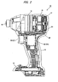
FIG. 2 is a side view illustrating an internal structure of the power tool; -
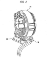
FIG. 3 is an enlarged perspective view of a motor and a motor control board; -
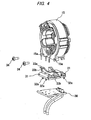
FIG. 4 is an exploded perspective view of the motor and the motor control board; -
FIG. 5A is a perspective view of a coupling unit when seen from a top at an angle; -
FIG. 5B is a perspective view of the coupling unit when seen from a bottom at an angle; -
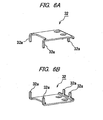
FIG. 6A is a perspective view of a junction plate when seen from a top at an angle; -
FIG. 6B is a perspective view of the junction plate when seen from a bottom at an angle; -
FIG. 7A is a plan view of the motor control board; and -
FIG. 7B is a bottom view of the motor control board. - Hereinafter, an embodiment of the present invention will be described with reference to the drawings.
- A
power tool 10 according to the embodiment is an impact driver equipped with amotor 15. - As illustrated in
FIG. 1 , ahousing 11 of thepower tool 10 includes atubular output part 12, agrip part 13 extending from a lower portion of theoutput part 12 in a direction substantially perpendicular to theoutput part 12, and a batterypack mounting part 14 provided at a lower portion of thegrip part 13. - As illustrated in
Fig. 2 , themotor 15 is built in theoutput part 12. Theoutput part 12 is provided therein with acooling fan 17, a spindle, an impact mechanism, and an anvil, which are not illustrated, and they are installed in series coaxially with a rotation shaft of themotor 15. Below themotor 15, amotor control board 30 configured to control themotor 15 is disposed. Themotor control board 30 is disposed in a space between themotor 15 and atrigger switch 21 at a connection position between theoutput part 12 and thegrip part 13 in such a manner that a surface of themotor control board 30 faces themotor 15. Themotor control board 30 is connected to thetrigger switch 21, a lighting operation board not illustrated but provided near the batterypack mounting part 14, and a battery, via electric wires and the like. - A front end of the anvil is provided with an
output shaft 16. A driver bit (tip tool) can be mounted to theoutput shaft 16. If themotor 15 is driven in a state in which the driver bit is attached to theoutput shaft 16, the driver bit is rotated by a driving force of themotor 15 to fasten a screw. - The
cooling fan 17 is disposed at the rearmost portion of theoutput shaft 12, and is rotated synchronous with the rotation of themotor 15. Accordingly, fresh air is sucked from an inlet port 19 (seeFIG. 1 ) which is opened on a lateral portion of thehousing 11, and the sucked air is discharged outwardly from an outlet port 20 (seeFIG. 1 ) which is opened on the lateral portion of thehousing 11. - The
inlet port 19 is provided at the side of themotor control board 30, and theoutlet port 20 is provided at the side of thecooling fan 17. Accordingly, when thecooling fan 17 is operated, the cooling air sucked by thecooking fan 17 from theintake port 19 passes through the inside of themotor 15 from the vicinity of themotor control board 30, and then is discharged outward from theoutlet port 20, thereby effectively cooling a coil of themotor 15 and themotor control board 30. - The
grip part 13 is a part for allowing an operator to grip thepower tool 10. As illustrated inFIG. 1 , thetrigger switch 21 is disposed at the front of thepower tool 10 near a boundary line between theoutput part 12 and thegrip part 13. - The
trigger switch 21 is configured to activate themotor 15. As illustrated inFIG. 2 , thetrigger switch 21 has a box-like switch body 22 receiving a contact point of the switch, and atrigger portion 23 which can be pushed against theswitch body 22. Thetrigger switch 21 is accommodated in thegrip part 13. Thetrigger portion 23 protrudes outwardly from thehousing 11, so that the trigger portion can be operated. As thetrigger portion 23 is triggered, themotor 15 starts to rotate, thereby initiating the operation of thepower tool 10. Thetrigger portion 23 is disposed at a position so that it is caught by an index finger when thegrip part 13 is grasped. - The
motor 15 is a brushless DC motor of three-phase alternating current, and is driven by turning aswitching device 30a, such as FET, on and off. Theswitching device 30a is mounted on themotor control board 30. - As illustrated in
FIG. 3 , themotor control board 30 is fixed to themotor 15, and acoupling unit 31 installed below a bottom surface of themotor 15 is interposed between themotor 15 andmotor control board 30. Accordingly, as illustrated inFIG. 2 , themotor control board 30 is disposed in a space between themotor 15 and thetrigger switch 21. - As illustrated in
FIGs. 5A and 5B , thecoupling unit 31 has ametallic junction plate 32 serving as a conduction portion, and aplate cover 33 made of resin installed to cover thejunction plate 32. - The
junction plate 32 is insert-molded with theplate cover 33, andonly leg portion 32a of thejunction plate 32 is exposed. - An upper portion of the
plate cover 33 is provided with aprotrusion 33a. Theprotrusion 33a is penetrated by fixingholes 33b. A rear surface of theplate cover 33 is provided with aconcave portion 33d having the substantially same size as thejunction plate 32. - As illustrated in
FIGs. 6A and 6B , thejunction plate 32 is formed by bending an end portion of a board-like metallic member at a substantially right angle. Thejunction plate 32 has four leg portions32a in total, in which two legs are in front and two legs are in rear. The number and position of the legs are optional. As illustrated inFIG. 5B , when thejunction plate 32 is fixed to theplate cover 33, theleg portions 32a protrude outwardly from leg portion through-holes 33c of theplate cover 33. - When the
motor 15 and thecoupling unit 31 are fixed, screws 34 penetrate the fixingholes 33b of theplate cover 33, and then are screwed to screwholes 15a of the motor 15 (seeFIG. 4 ). - When the
coupling unit 31 and themotor control board 30 are fixed, theleg portions 32a of thejunction plate 32 are inserted into junctionplate connecting portions 30c of themotor control board 30, and then theleg portions 32a are fixed to the junctionplate connecting portions 30c by soldering. - As illustrated in
FIGs. 7A and 7B , themotor control board 30 is formed in a shape of a substantially rectangular thin plate. Sixswitching devices 30a are mounted on the surface of themotor control board 30 to convert the supply of power in a U-phase, a V-phase, and a W-phase of themotor 15. Themotor control board 30 has three motorcoil connecting portions 30b which are connected to coils of themotor 15. Themotor control board 30 is provided with a pattern to connect theswitching devices 30a and the motorcoil connecting portions 30b. - The pattern is configured so that a portion (in particular, a long connection portion) of the wiring is omitted. That is, the circuit is not completed only by the
motor control board 30. The junctionplate connecting portions 30c are formed at a position corresponding to an end of the omitted wiring. The as theleg portions 32a of thejunction plate 32 are inserted and fixed to the junctionplate connecting portions 30c by soldering, each of the junction plate connecting portions is electrically connected to each other. That is, thejunction plate 32 serves as a jumper for completing the circuit on themotor control board 30. - The
motor control board 30 is fixed to thejunction plate 32 by soldering. Themotor control board 30 is further fixed to thejunction plate 32 by an adhesive for coating the surface of themotor control board 30. - As described above, according to this embodiment, the
motor control board 30 is fixed to themotor 15 via thecoupling unit 31 provided below the motor 15 (e.g., at the bottom surface of the motor 15). For this reason, since it is not necessary to provide themotor control board 30 with a screw bearing surface, themotor control board 30 can be reduced in size. The downsizedmotor control board 30 is disposed below themotor 15 and above the trigger switch 21 (e.g., in the space between the bottom surface of themotor 15 and the upper surface of the trigger switch 21), so that the reduction in axial length of the entire tool and the cooling of theswitching devices 30a are both realized. Further, since the entire tool is downsized, it is possible to reduce in weight of the tool. - The
coupling unit 31 has thejunction plate 32 as an electrically conductive portion. Themotor control board 30 is fixed to thejunction plate 32 by soldering, and thus is fixed to the motor. Also, the junction plate 32is configured to serve as the jumper to complete the circuit on themotor control board 30. For this reason, since a pattern of a power line occupying a large ratio in an area of themotor control board 30 can be omitted, themotor control board 30 can be further downsized. - The
motor control board 30 is fixed to thejunction plate 32 by the adhesive for coating themotor control board 30. Using the adhesive can obtain an effect, such as insulation of the motor control board, and can absorb vibration of themotor 15 to render themotor control board 30 not to have an effect of the vibration. - In the above-described embodiment, the
coupling unit 31 is provided as a separate body with respect to themotor 15, but the present invention is not limited thereto. For example, thecoupling unit 31 may be formed integrally with themotor 15. - Further, in the above-described embodiment, although the
coupling unit 31 and themotor control board 30 are fixed to each other by the soldering, the present invention is not limited thereto, and they may be fixed by the adhesive or the like. Similarly, themotor control board 30 and thejunction plate 32 are fixed to each other by the soldering, but may be fixed to each other by riveting or adhesive.
Claims (5)
- A power tool (10) comprising:a housing (11):a motor (15) accommodated in the housing (11);a cooling fan (17) arranged coaxially with the motor (15);a trigger switch (21) configured to activate the motor (15);a motor control board (30) on which a switching device (30a) is mounted to drive the motor (15); anda coupling unit (31) provided below the motor (15),wherein the motor control board (30) is fixed to the motor (15) via the coupling unit (31) such that the motor control board (30) is disposed below the motor (15) and above the trigger switch (21).
- The power tool (10) according to claim 1, wherein the coupling unit (31) comprises an electrically conductive portion (32),
wherein the motor control board (30) is fixed to the electrically conductive portion (32), and
wherein the electrically conductive portion (32) is configured as a jumper to complete a circuit on the motor control board (30). - The power tool (10) according to claim 2, wherein the motor control board (30) is fixed to the electrically conductive portion (32) by soldering.
- The power tool (10) according to any one of claims 1 to 3, wherein the motor control board (30) is fixed to the coupling unit (31) by an adhesive.
- The power tool (10) according to claim 4, wherein the motor control board (30) is coated with the adhesive.
Applications Claiming Priority (1)
| Application Number | Priority Date | Filing Date | Title |
|---|---|---|---|
| JP2012111312A JP5942580B2 (en) | 2012-05-15 | 2012-05-15 | Electric tool |
Publications (2)
| Publication Number | Publication Date |
|---|---|
| EP2664419A2 true EP2664419A2 (en) | 2013-11-20 |
| EP2664419A3 EP2664419A3 (en) | 2015-12-30 |
Family
ID=48484974
Family Applications (1)
| Application Number | Title | Priority Date | Filing Date |
|---|---|---|---|
| EP13002553.9A Withdrawn EP2664419A3 (en) | 2012-05-15 | 2013-05-15 | Power tool |
Country Status (5)
| Country | Link |
|---|---|
| US (1) | US9293964B2 (en) |
| EP (1) | EP2664419A3 (en) |
| JP (1) | JP5942580B2 (en) |
| CN (1) | CN103419162B (en) |
| TW (1) | TWI572465B (en) |
Cited By (2)
| Publication number | Priority date | Publication date | Assignee | Title |
|---|---|---|---|---|
| US20220247279A1 (en) * | 2019-07-11 | 2022-08-04 | Makita Corporation | Electric powered work machine |
| US20250256384A1 (en) * | 2015-10-14 | 2025-08-14 | Black & Decker Inc. | Brushless motor for power tools |
Families Citing this family (4)
| Publication number | Priority date | Publication date | Assignee | Title |
|---|---|---|---|---|
| US10478950B2 (en) | 2015-11-26 | 2019-11-19 | Makita Corporation | Power tool |
| US10594246B2 (en) * | 2017-12-26 | 2020-03-17 | Eaton Intelligent Power Limited | Board-level motor control system with integrated protection and control components |
| US11251741B2 (en) | 2018-11-15 | 2022-02-15 | Eaton Intelligent Power Limited | Modular board-level motor control system with integrated protection and control components |
| CN114876827A (en) | 2021-02-05 | 2022-08-09 | 创科无线普通合伙 | Hair drier |
Citations (1)
| Publication number | Priority date | Publication date | Assignee | Title |
|---|---|---|---|---|
| JP4436033B2 (en) | 2002-10-07 | 2010-03-24 | 日本電産シバウラ株式会社 | Inverter circuit wiring structure and power tool |
Family Cites Families (12)
| Publication number | Priority date | Publication date | Assignee | Title |
|---|---|---|---|---|
| CH608918A5 (en) * | 1975-10-17 | 1979-01-31 | Bosch Gmbh Robert | |
| EP1000215B1 (en) * | 1998-02-05 | 2003-05-07 | Robert Bosch Gmbh | Electronic module for a drive unit powered by an electrical motor |
| JP3786356B2 (en) * | 2002-04-26 | 2006-06-14 | 株式会社デンソー | Inverter-integrated electric compressor for vehicles |
| US7414337B2 (en) * | 2005-03-14 | 2008-08-19 | Black & Decker Inc. | Scrubber |
| JP4939673B2 (en) * | 2005-05-11 | 2012-05-30 | 日本電産テクノモータホールディングス株式会社 | Trigger switch and motor drive circuit using the same |
| JP2006333587A (en) | 2005-05-24 | 2006-12-07 | Nidec Shibaura Corp | Motor system |
| JP2006340555A (en) * | 2005-06-03 | 2006-12-14 | Nidec Shibaura Corp | Motor system |
| JP2007268634A (en) * | 2006-03-30 | 2007-10-18 | Max Co Ltd | Power tool |
| JP2008173716A (en) * | 2007-01-18 | 2008-07-31 | Max Co Ltd | Electric power tool having brushless motor |
| US8253285B2 (en) * | 2007-04-27 | 2012-08-28 | Hitachi Koki Co., Ltd. | Power tool |
| JP4974054B2 (en) | 2007-04-27 | 2012-07-11 | 日立工機株式会社 | Electric tool |
| JP5522504B2 (en) * | 2008-09-29 | 2014-06-18 | 日立工機株式会社 | Electric tool |
-
2012
- 2012-05-15 JP JP2012111312A patent/JP5942580B2/en active Active
-
2013
- 2013-05-14 US US13/893,715 patent/US9293964B2/en active Active
- 2013-05-14 TW TW102116976A patent/TWI572465B/en active
- 2013-05-15 EP EP13002553.9A patent/EP2664419A3/en not_active Withdrawn
- 2013-05-15 CN CN201310179882.8A patent/CN103419162B/en active Active
Patent Citations (1)
| Publication number | Priority date | Publication date | Assignee | Title |
|---|---|---|---|---|
| JP4436033B2 (en) | 2002-10-07 | 2010-03-24 | 日本電産シバウラ株式会社 | Inverter circuit wiring structure and power tool |
Cited By (3)
| Publication number | Priority date | Publication date | Assignee | Title |
|---|---|---|---|---|
| US20250256384A1 (en) * | 2015-10-14 | 2025-08-14 | Black & Decker Inc. | Brushless motor for power tools |
| US20220247279A1 (en) * | 2019-07-11 | 2022-08-04 | Makita Corporation | Electric powered work machine |
| US12142971B2 (en) * | 2019-07-11 | 2024-11-12 | Makita Corporation | Electric powered work machine |
Also Published As
| Publication number | Publication date |
|---|---|
| CN103419162B (en) | 2016-08-03 |
| JP2013237118A (en) | 2013-11-28 |
| US9293964B2 (en) | 2016-03-22 |
| US20130307355A1 (en) | 2013-11-21 |
| EP2664419A3 (en) | 2015-12-30 |
| CN103419162A (en) | 2013-12-04 |
| JP5942580B2 (en) | 2016-06-29 |
| TW201410411A (en) | 2014-03-16 |
| TWI572465B (en) | 2017-03-01 |
Similar Documents
| Publication | Publication Date | Title |
|---|---|---|
| US9293964B2 (en) | Power tool | |
| US9314900B2 (en) | Handheld grinder with a brushless electric motor | |
| US20200186006A1 (en) | Handheld power tool with a brushless electric motor | |
| JP6730418B2 (en) | Electric work machine | |
| US20160020676A1 (en) | Electric power tool | |
| US9871424B2 (en) | Electric tool | |
| US20110180286A1 (en) | Electric Power Tool | |
| US20210060754A1 (en) | Power tool | |
| CN112041124B (en) | electrical tools | |
| US12142971B2 (en) | Electric powered work machine | |
| US20210362289A1 (en) | Electric work machine | |
| JP5541435B2 (en) | Electric tool | |
| JP2016187865A (en) | Electric tool | |
| JP6724563B2 (en) | tool | |
| JP7061915B2 (en) | Circular saw | |
| JP2018187702A (en) | Electric tool | |
| CN112638591B (en) | electrical tools | |
| JP5974456B2 (en) | Electric tool | |
| CN115083810A (en) | Integrated electronic switch and electric tool | |
| US11842860B2 (en) | Integrated electronic switch and power tool | |
| JP2021160045A (en) | Work machine | |
| JP2017056538A (en) | Electric tool |
Legal Events
| Date | Code | Title | Description |
|---|---|---|---|
| PUAI | Public reference made under article 153(3) epc to a published international application that has entered the european phase |
Free format text: ORIGINAL CODE: 0009012 |
|
| AK | Designated contracting states |
Kind code of ref document: A2 Designated state(s): AL AT BE BG CH CY CZ DE DK EE ES FI FR GB GR HR HU IE IS IT LI LT LU LV MC MK MT NL NO PL PT RO RS SE SI SK SM TR |
|
| AX | Request for extension of the european patent |
Extension state: BA ME |
|
| PUAL | Search report despatched |
Free format text: ORIGINAL CODE: 0009013 |
|
| AK | Designated contracting states |
Kind code of ref document: A3 Designated state(s): AL AT BE BG CH CY CZ DE DK EE ES FI FR GB GR HR HU IE IS IT LI LT LU LV MC MK MT NL NO PL PT RO RS SE SI SK SM TR |
|
| AX | Request for extension of the european patent |
Extension state: BA ME |
|
| RIC1 | Information provided on ipc code assigned before grant |
Ipc: B25F 5/00 20060101AFI20151120BHEP |
|
| 17P | Request for examination filed |
Effective date: 20160630 |
|
| RBV | Designated contracting states (corrected) |
Designated state(s): AL AT BE BG CH CY CZ DE DK EE ES FI FR GB GR HR HU IE IS IT LI LT LU LV MC MK MT NL NO PL PT RO RS SE SI SK SM TR |
|
| GRAP | Despatch of communication of intention to grant a patent |
Free format text: ORIGINAL CODE: EPIDOSNIGR1 |
|
| INTG | Intention to grant announced |
Effective date: 20181018 |
|
| STAA | Information on the status of an ep patent application or granted ep patent |
Free format text: STATUS: THE APPLICATION IS DEEMED TO BE WITHDRAWN |
|
| 18D | Application deemed to be withdrawn |
Effective date: 20190301 |