EP2664410B1 - Methods of fabricating fuel injectors using laser additive deposition - Google Patents
Methods of fabricating fuel injectors using laser additive deposition Download PDFInfo
- Publication number
- EP2664410B1 EP2664410B1 EP13167453.3A EP13167453A EP2664410B1 EP 2664410 B1 EP2664410 B1 EP 2664410B1 EP 13167453 A EP13167453 A EP 13167453A EP 2664410 B1 EP2664410 B1 EP 2664410B1
- Authority
- EP
- European Patent Office
- Prior art keywords
- alloy
- feed arm
- fuel injector
- includes depositing
- additive deposition
- Prior art date
- Legal status (The legal status is an assumption and is not a legal conclusion. Google has not performed a legal analysis and makes no representation as to the accuracy of the status listed.)
- Active
Links
Images





Classifications
-
- F—MECHANICAL ENGINEERING; LIGHTING; HEATING; WEAPONS; BLASTING
- F23—COMBUSTION APPARATUS; COMBUSTION PROCESSES
- F23R—GENERATING COMBUSTION PRODUCTS OF HIGH PRESSURE OR HIGH VELOCITY, e.g. GAS-TURBINE COMBUSTION CHAMBERS
- F23R3/00—Continuous combustion chambers using liquid or gaseous fuel
- F23R3/28—Continuous combustion chambers using liquid or gaseous fuel characterised by the fuel supply
- F23R3/283—Attaching or cooling of fuel injecting means including supports for fuel injectors, stems, or lances
-
- B—PERFORMING OPERATIONS; TRANSPORTING
- B23—MACHINE TOOLS; METAL-WORKING NOT OTHERWISE PROVIDED FOR
- B23K—SOLDERING OR UNSOLDERING; WELDING; CLADDING OR PLATING BY SOLDERING OR WELDING; CUTTING BY APPLYING HEAT LOCALLY, e.g. FLAME CUTTING; WORKING BY LASER BEAM
- B23K26/00—Working by laser beam, e.g. welding, cutting or boring
- B23K26/20—Bonding
- B23K26/32—Bonding taking account of the properties of the material involved
-
- B—PERFORMING OPERATIONS; TRANSPORTING
- B23—MACHINE TOOLS; METAL-WORKING NOT OTHERWISE PROVIDED FOR
- B23K—SOLDERING OR UNSOLDERING; WELDING; CLADDING OR PLATING BY SOLDERING OR WELDING; CUTTING BY APPLYING HEAT LOCALLY, e.g. FLAME CUTTING; WORKING BY LASER BEAM
- B23K26/00—Working by laser beam, e.g. welding, cutting or boring
- B23K26/34—Laser welding for purposes other than joining
- B23K26/342—Build-up welding
-
- B—PERFORMING OPERATIONS; TRANSPORTING
- B23—MACHINE TOOLS; METAL-WORKING NOT OTHERWISE PROVIDED FOR
- B23K—SOLDERING OR UNSOLDERING; WELDING; CLADDING OR PLATING BY SOLDERING OR WELDING; CUTTING BY APPLYING HEAT LOCALLY, e.g. FLAME CUTTING; WORKING BY LASER BEAM
- B23K35/00—Rods, electrodes, materials, or media, for use in soldering, welding, or cutting
- B23K35/001—Interlayers, transition pieces for metallurgical bonding of workpieces
-
- B—PERFORMING OPERATIONS; TRANSPORTING
- B23—MACHINE TOOLS; METAL-WORKING NOT OTHERWISE PROVIDED FOR
- B23K—SOLDERING OR UNSOLDERING; WELDING; CLADDING OR PLATING BY SOLDERING OR WELDING; CUTTING BY APPLYING HEAT LOCALLY, e.g. FLAME CUTTING; WORKING BY LASER BEAM
- B23K35/00—Rods, electrodes, materials, or media, for use in soldering, welding, or cutting
- B23K35/001—Interlayers, transition pieces for metallurgical bonding of workpieces
- B23K35/004—Interlayers, transition pieces for metallurgical bonding of workpieces at least one of the workpieces being of a metal of the iron group
-
- B—PERFORMING OPERATIONS; TRANSPORTING
- B23—MACHINE TOOLS; METAL-WORKING NOT OTHERWISE PROVIDED FOR
- B23K—SOLDERING OR UNSOLDERING; WELDING; CLADDING OR PLATING BY SOLDERING OR WELDING; CUTTING BY APPLYING HEAT LOCALLY, e.g. FLAME CUTTING; WORKING BY LASER BEAM
- B23K2103/00—Materials to be soldered, welded or cut
- B23K2103/02—Iron or ferrous alloys
- B23K2103/04—Steel or steel alloys
- B23K2103/05—Stainless steel
-
- B—PERFORMING OPERATIONS; TRANSPORTING
- B23—MACHINE TOOLS; METAL-WORKING NOT OTHERWISE PROVIDED FOR
- B23K—SOLDERING OR UNSOLDERING; WELDING; CLADDING OR PLATING BY SOLDERING OR WELDING; CUTTING BY APPLYING HEAT LOCALLY, e.g. FLAME CUTTING; WORKING BY LASER BEAM
- B23K2103/00—Materials to be soldered, welded or cut
- B23K2103/18—Dissimilar materials
- B23K2103/26—Alloys of Nickel and Cobalt and Chromium
-
- B—PERFORMING OPERATIONS; TRANSPORTING
- B33—ADDITIVE MANUFACTURING TECHNOLOGY
- B33Y—ADDITIVE MANUFACTURING, i.e. MANUFACTURING OF THREE-DIMENSIONAL [3D] OBJECTS BY ADDITIVE DEPOSITION, ADDITIVE AGGLOMERATION OR ADDITIVE LAYERING, e.g. BY 3D PRINTING, STEREOLITHOGRAPHY OR SELECTIVE LASER SINTERING
- B33Y80/00—Products made by additive manufacturing
-
- Y—GENERAL TAGGING OF NEW TECHNOLOGICAL DEVELOPMENTS; GENERAL TAGGING OF CROSS-SECTIONAL TECHNOLOGIES SPANNING OVER SEVERAL SECTIONS OF THE IPC; TECHNICAL SUBJECTS COVERED BY FORMER USPC CROSS-REFERENCE ART COLLECTIONS [XRACs] AND DIGESTS
- Y10—TECHNICAL SUBJECTS COVERED BY FORMER USPC
- Y10T—TECHNICAL SUBJECTS COVERED BY FORMER US CLASSIFICATION
- Y10T29/00—Metal working
- Y10T29/49—Method of mechanical manufacture
- Y10T29/494—Fluidic or fluid actuated device making
Definitions
- the subject invention relates to the fabrication and assembly of fuel injectors for gas turbine engines, and more particularly, to methods of fabricating and assembling fuel injectors using laser additive deposition techniques to locally enhance the mechanical properties of the fuel injector.
- Gas turbines engines used in military and commercial aircraft must satisfy high demands with respect to reliability, weight, performance, economic efficiency and durability.
- the use of advanced manufacturing methods and materials selection play a decisive role in meeting these requirements.
- Conventional methods for manufacturing gas turbine components include forging and investment casting.
- the highly stressed components in the compressor region of a gas turbine are typically manufactured by forging, whereas the rotor and stator blades of the turbine are typically manufactured by investment casting.
- Another known method of manufacturing, repairing or restoring blades used in gas turbine engines is laser consolidation.
- a laser is used to create a melt pool at a metal surface during which metal or ceramic powder is delivered by a nozzle into the melt pool to build up a three dimensional geometry. Examples of this process are disclosed in U.S. Patent No. 6,269,540 to Islam et al. and U.S. Patent No. 7,984,547 to Steinhardt .
- Material selection for gas turbine components that are subjected to high mechanical loads, high vibration loads or high thermal loads is often based upon material limits being exceeded in localized regions of the component. Exceeding the material limits in a local region often causes the designer of the component to specify high-strength or otherwise exotic alloy materials for fabricating the entire component. The selection of an exotic material for the entire component tends to drive its cost up substantially.
- the subject invention provides for the use of laser cladding or additive manufacturing processes to locally improve the material properties of a gas turbine component, and more particularly, a fuel injector used within a gas turbine engine.
- an improved material can be applied in areas where improved properties may be needed for strength, vibration or thermal management.
- an improved material can be used in localized areas, a manufacturer can save cost and weight on the overall component design, while meeting the same certification or equal requirements provided for a standard component.
- WO 01/40710 A1 discloses a method of assembling a fuel injector for a gas turbine engine in which a fuel nozzle is brazed onto a stem body.
- the present invention provides a new and useful method of fabricating a fuel injector comprising the steps of forming or otherwise machining a structural portion of a fuel injector from an alloy having a first mechanical property, and then adding an alloy having a second mechanical property that is different from the first mechanical property on a surface area of the structural portion of the fuel injector to enhance the mechanical properties of the fuel injector.
- the subject invention is directed to a method of fabricating a fuel injector that includes the steps of forming a feed arm of a fuel injector from a relatively low strength alloy and then laser adding a relatively high strength alloy on a surface area of the feed arm corresponding to a location of high stress concentration to reduce manufacturing cost and enhance the mechanical properties of the fuel injector in that localized area.
- the step of adding may include depositing material on a front surface area of the feed arm, on a rear surface area of the feed arm or on front and rear surface areas of the feed arm, to locally reinforce those regions of high stress, in order to meet bird strike requirements set by an engine manufacture.
- the step of adding could also include depositing material in a recessed area formed in a front surface of the feed arm, in a rear surface of the feed arm or in recessed areas formed in front and rear surfaces of the feed arm. This provides improved bonding and additional localized cladding thickness on the surfaces of the feed arm, to further enhance the mechanical properties of the fuel injector in those localized areas.
- the method may include the step of depositing material on surfaces of a tip portion the feed arm adjacent the nozzle body of the fuel injector, or in recessed areas formed in surfaces of a tip portion of the feed arm adjacent the nozzle body, at locations of high stress concentration, in order to meet vibration requirements set by an engine manufacture.
- the subject invention is also directed to a method of fabricating a fuel injector that includes the steps of forming or otherwise machining a structural portion of the fuel injector (e.g., a feed arm of the fuel injector) from an alloy having a first thermal expansion characteristic, and then adding an alloy having a second thermal expansion characteristic on an external surface area of the feed arm to produce compressive stress in a desired location.
- a structural portion of the fuel injector e.g., a feed arm of the fuel injector
- the material is deposited on opposed lateral surfaces of the feed arm, and it can also be deposited in recessed area formed in opposed lateral surface of the feed arm to improve bonding and provide additional localized cladding thickness.
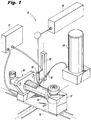
- Fig. 1 a schematic representation of a system for fabricating engine components using an additive manufacturing process, which is designated generally by reference numeral 10.
- additive manufacturing process encompasses techniques such as laser additive deposition, laser metal deposition, direct laser deposition, direct metal deposition, laser cladding and the like.
- the work piece 50 is in the form of a fuel injector used to deliver fuel and air into the combustion chamber of a gas turbine engine.
- a fuel injector used to deliver fuel and air into the combustion chamber of a gas turbine engine.
- the two axis stage 12 is adapted and configured to translate the work piece 50 in relative X and Y planes during the additive deposition process.
- the system 10 further includes a laser 16 that includes focusing optics 18 supported on a CNC motion controlled vertical stage 20 mounted for movement in a Z plane relative the two axis stage 12. It is envisioned that a five-axis motion system can also be employed, which would include a two-axis (X-Y) motion bed, a two-axis (B-C) tool orientation head that angles and rotates the work piece, and a fifth axis (Z) for moving the focusing optics of the laser.
- X-Y two-axis
- B-C two-axis
- Z fifth axis
- a suitable laser for use with the system 10 would be a Nd:YAG laser (500W or 1000W), or an equivalent thereof. It is envisioned that a 500W pulse laser or a 4kW continuous laser can be employed with the system disclosed herein.
- a computer guided motion controller 22 controls the movement of the two axis stage 12 supporting the work piece 50 and the vertical stage 20 supporting the laser optics 18 in accordance with a set of instructions relating to the production of a desired structural feature.
- System 10 also includes a powder feeder 24 which delivers metallic powder to a nozzle 26. The interaction of powdered metal from the nozzle 26 and the laser 16/18 causes melting to occur, and is commonly referred to as the melt pool. This is deposited onto a surface of the work piece 50. Moving the work piece 50 upon stage 12 allows the melt pool to solidify and thus produces a track of solid metal in a desired location, as illustrated in Fig. 1 .
- the laser additive deposition process of the subject invention is particularly useful for locally improving the metallurgical properties of an engine component in selected regions where it is most needed and only in those regions. For example, in cases where an engine manufacturer sets bird strike requirements for a fuel injector, the designer of that engine component must typically manufacture the entire feed arm of the injector from expensive high-strength, corrosion resistant super alloys such as, for example, nickel-chromium based Inconel® alloy 718 or nickel-based Waspaloy.
- the feed arm of the fuel injector is advantageously fabricated from a less expensive and relatively lower strength alloy, such as Hastelloy® X alloy, which is a nickel-chromium-iron-molybdenum alloy that possesses exceptional forming and welding characteristics.
- a layer of Inconel® alloy 718 or Waspaloy is then deposited onto a specified surface area of the Hastelloy® X alloy feed arm by laser additive deposition, to mechanically reinforce only the locally stressed region(s) of the feed arm, and thereby meet the bird strike requirements set by the engine manufacturer in a more cost effective manner.
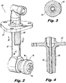
- a fuel injector fabricated in accordance with this method is illustrated for example in Figs. 2-4 .
- the feed arm 52 of fuel injector 50 is made from a relatively low-strength alloy such as, for example, Hastelloy® X alloy, and a relatively high-strength alloy, such as, for example, Inconel® alloy 718 or Waspaloy, is deposited onto a front surface area 54 of the feed arm 52 adjacent the mounting flange 55 using laser additive deposition, to enhance the mechanical properties of the fuel injector 50 in that localized area, and only that area, and thereby meet bird strike requirements.
- a relatively low-strength alloy such as, for example, Hastelloy® X alloy
- a relatively high-strength alloy such as, for example, Inconel® alloy 718 or Waspaloy
- the feed arm 52 of fuel injector 50 is made from a relatively low strength alloy (e.g., Hastelloy® X alloy) and a relatively high strength alloy (e.g., Inconel® alloy 718 or Waspaloy) is deposited into a recess 56 formed in a front surface area 54 of the feed arm 52 adjacent the mounting flange 55 using laser additive deposition.
- a relatively low strength alloy e.g., Hastelloy® X alloy
- a relatively high strength alloy e.g., Inconel® alloy 718 or Waspaloy
- the feed arm 52 of fuel injector 50 is made from a relatively low strength alloy (e.g., Hastelloy® X alloy) and a relatively high strength alloy (e.g., Inconel® alloy 718 or Waspaloy) is deposited onto a rear surface area 58 of the feed arm 52 adjacent the mounting flange 55 using laser additive deposition to enhance the mechanical properties of the fuel injector 50 in that localized area.
- a relatively low strength alloy e.g., Hastelloy® X alloy
- a relatively high strength alloy e.g., Inconel® alloy 718 or Waspaloy
- the relatively high strength alloy is deposited into a recess 60 formed in a rear surface area 58 of the feed arm 52 to further enhance the mechanical properties of the fuel injector 50 in that localized area.
- the feed arm 52 of fuel injector 50 made from a relatively low strength alloy (e.g., Hastelloy® X alloy) and a relatively high strength alloy (e.g., Inconel® alloy 718 or Waspaloy) is deposited onto the front and rear surface areas 54 and 58 of the feed arm 52 adjacent the mounting flange 55 using laser additive deposition to enhance the mechanical properties of the fuel injector 50 only in those localized areas.
- a relatively low strength alloy e.g., Hastelloy® X alloy
- a relatively high strength alloy e.g., Inconel® alloy 718 or Waspaloy
- the relatively high strength alloy is deposited into recesses 56 and 60 formed in the front and rear surface areas 54 and 58 of feed arm 52 using laser additive deposition to further enhance the mechanical properties of the fuel injector 50 only in those localized areas.
- the feed arm 52 of fuel injector 50 is made from a relatively low strength alloy (e.g., Hastelloy® X alloy) and a relatively high strength alloy (e.g., Inconel® alloy 718 or Waspaloy) is deposited on a circumferential surface area 62 of the feed arm 52 adjacent the mounting flange 55 using laser additive deposition to enhance the mechanical properties of the fuel injector 50 only in that area feed arm.
- a relatively low strength alloy e.g., Hastelloy® X alloy
- a relatively high strength alloy e.g., Inconel® alloy 718 or Waspaloy
- the relatively high strength alloy is deposited in a circumferential recessed area 64 formed therein using laser additive deposition, to further enhance the mechanical properties of the fuel injector 50 only in that area of the feed arm.
- the additive deposition process of the subject invention can also be used to meet vibration requirements set by engine manufacturers.
- local patches of relatively high strength alloy are additively deposited onto a feed arm fabricated from a relatively low-cost, low strength alloy, based upon the identification of highly stressed regions of that component. These stressed regions are predicted through vibration analysis performed by the component designer.
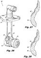
- FIGs. 26 and 27 An example of an engine component fabricated in this manner is shown in Figs. 26 and 27 , wherein the feed arm 52 of fuel injector 50 is made from a relatively low strength alloy, such as Hastelloy® X alloy.
- a relatively high strength alloy such as Inconel® alloy 718 or Waspaloy is deposited by laser additive deposition on highly stressed lateral surfaces 65 and 67 at or near the tip portion 66 the feed arm 52, adjacent the nozzle body 70, to meet a manufacturer's vibration requirements for the fuel injector.
- the high strength alloy can also be deposited in a recessed area 68 at the tip portion 66 feed arm 52 to improve bonding and increase cladding thickness.
- a laser additive deposition process may also be used to locally improve the processing properties of an engine component in regions where it is most needed and only in those regions.
- many high strength materials are heavily alloyed, which can be good for component life but can be bad for special material processing steps such as brazing.
- the additive deposition process of the subject invention can be advantageously used to provide a local inert surface that is intended to be half of a braze joint.
- fuel injector 50 has a feed arm 52 fabricated from an alloy that is difficult to braze, such as, for example, Inconel® alloy 718. Hastelloy® X alloy or a stabilized stainless steel alloy such as 347 Stainless Steel is deposited by laser additive deposition onto a surface of the feed arm 52 to form a braze surface joint 75. More particularly, as best seen in Fig. 30 , there is a nozzle body 70 at the end of the tip portion 66 the feed arm 52.
- an alloy that is not difficult to braze e.g., Hastelloy® X alloy
- Hastelloy® X alloy is deposited onto an interior surface of the tip portion 66 of the feed arm 52 formed from Inconel® alloy 718 to form a braze joint 75 between an injector component 72 of the nozzle body 70 and the feed arm 52, which is best seen in Fig. 31 .
- a laser additive deposition process may also be used to provide a local inert region that is intended to be half of a weld joint that joins two complementary parts of an engine component together.
- a material such as Hastelloy® X alloy or Inconel® 625 alloy, which are both easily weldable, is deposited by laser additive deposition onto a surface of a high temperature, high strength alloy component made from Inconel® 718 or Waspaloy, just at the weld joint region. The two components are then welded together. This eliminates the need for post weld heat treatment when the component is fabricated only from Inconel® 718 or Waspaloy.
- fuel injector 50 has a feed arm 52 and inlet fitting 76 are machined from an alloy that is relatively difficult to weld (e.g., Inconel® 718 or Waspaloy).
- a weld joint 74 is formed by adding an alloy that is not difficult to weld (e.g., Hastelloy® X alloy or Inconel® 625 alloy) onto a surface of the feed arm 52 to join an inlet fitting 76 to the feed arm 52.
- the laser additive deposition process of the subject invention is also used to provide a preload characteristic to an engine component.
- an alloy with a particular thermal expansion characteristic is additively deposited on the external surface(s) of a feed arm fabricated from an alloy having a different thermal expansion characteristic.
- the difference in thermal expansion characteristics of the alloys results in the formation of stress in the feed arm, which advantageously produces compressive stress in critical or desired locations of the component.
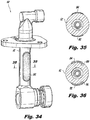
- feed arm 52 of fuel injector 50 is machined from an alloy having a first thermal expansion characteristic (e.g., 347 Stainless Steel alloy).
- An alloy having a second thermal expansion characteristic e.g., Inconel® 625 alloy
- the Inconel® 625 alloy is deposited in recessed areas 86 and 88 formed in lateral sides of the feed arm 52.
- a laser cladding process can also be used to protect known wear surfaces on engine components.
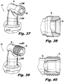
- Figs. 37-38 show the inlet fitting 76 of fuel injector 50 made from a relatively low hardness alloy, and an interior sealing surface 90 of the inlet fitting 76 is formed by depositing a relatively high hardness alloy onto that surface by laser additive deposition.
- the relatively high hardness alloy provides the sealing surface, while a material that has good manufacturability is used for the remainder of the component.
- Figs. 39-40 show the inlet fitting 76 of fuel injector 50 made from a relatively low hardness alloy, and the threaded surfaces 92 of the inlet fitting 76 are formed from a relatively high hardness alloy by laser additive deposition.
- the high hardness alloy provides thread strength, while the material with good manufacturability is used for the remainder of the component.
- a laser additive deposition process can be used to fabricate portions of fuel injector components that are subjected to the high operating temperatures that exists within the combustion chamber of a gas turbine engine.
- the converging outer air cap 94 of the nozzle body 70 shown in Fig. 2 can be fabricated using laser additive deposition.
- the air cap 94 is additively formed on top of the pre-existing outer air swirler 96, which is supported within a cradle 115 adjacent a metallic cladding wire 102 and laser optics 18.
- the air cap 94 is additively formed from an alloy that is more resistant to high engine operating temperatures than the alloy from which the air swirler 96 is formed.
- the air swirler 96 can be fabricated from Hastelloy® X alloy and the converging air cap 94 can be formed by depositing Haynes 230 or Haynes 214 onto the air swirler 96.
- FIGs. 43-45 illustrate several different feeding systems that are available for performing a laser additive deposition process such as that which is shown in Figs. 41-42 .
- These systems include the lateral injection nozzle 104 shown in Fig. 43 , the radially symmetric powder injection nozzles 106, 108 of Fig. 44 , and the conical nozzle 110 and coaxial powder stream 112 shown in Fig. 45 .
- Other feeding systems are also known in the art and can be employed in conjunction with the additive deposition system of the subject invention.
Landscapes
- Engineering & Computer Science (AREA)
- Mechanical Engineering (AREA)
- Physics & Mathematics (AREA)
- Optics & Photonics (AREA)
- Plasma & Fusion (AREA)
- Chemical & Material Sciences (AREA)
- Combustion & Propulsion (AREA)
- General Engineering & Computer Science (AREA)
- Fuel-Injection Apparatus (AREA)
- Laser Beam Processing (AREA)
Description
- The subject invention relates to the fabrication and assembly of fuel injectors for gas turbine engines, and more particularly, to methods of fabricating and assembling fuel injectors using laser additive deposition techniques to locally enhance the mechanical properties of the fuel injector.
- Gas turbines engines used in military and commercial aircraft must satisfy high demands with respect to reliability, weight, performance, economic efficiency and durability. Among other things, the use of advanced manufacturing methods and materials selection play a decisive role in meeting these requirements.
- Conventional methods for manufacturing gas turbine components include forging and investment casting. For example, the highly stressed components in the compressor region of a gas turbine are typically manufactured by forging, whereas the rotor and stator blades of the turbine are typically manufactured by investment casting.
- Another known method of manufacturing, repairing or restoring blades used in gas turbine engines is laser consolidation. In this process, a laser is used to create a melt pool at a metal surface during which metal or ceramic powder is delivered by a nozzle into the melt pool to build up a three dimensional geometry. Examples of this process are disclosed in
U.S. Patent No. 6,269,540 to Islam et al. andU.S. Patent No. 7,984,547 to Steinhardt . - Material selection for gas turbine components that are subjected to high mechanical loads, high vibration loads or high thermal loads is often based upon material limits being exceeded in localized regions of the component. Exceeding the material limits in a local region often causes the designer of the component to specify high-strength or otherwise exotic alloy materials for fabricating the entire component. The selection of an exotic material for the entire component tends to drive its cost up substantially.
- It would be desirable to employ techniques used for laser consolidation of entire engine components to locally improve or otherwise tailor the mechanical properties of an engine component. In this regard, the subject invention provides for the use of laser cladding or additive manufacturing processes to locally improve the material properties of a gas turbine component, and more particularly, a fuel injector used within a gas turbine engine.
- Thus, an improved material can be applied in areas where improved properties may be needed for strength, vibration or thermal management. By using an improved material in localized areas, a manufacturer can save cost and weight on the overall component design, while meeting the same certification or equal requirements provided for a standard component.
-
WO 01/40710 A1 - From a first aspect, the present invention provides a new and useful method of fabricating a fuel injector comprising the steps of forming or otherwise machining a structural portion of a fuel injector from an alloy having a first mechanical property, and then adding an alloy having a second mechanical property that is different from the first mechanical property on a surface area of the structural portion of the fuel injector to enhance the mechanical properties of the fuel injector.
- More particularly, the subject invention is directed to a method of fabricating a fuel injector that includes the steps of forming a feed arm of a fuel injector from a relatively low strength alloy and then laser adding a relatively high strength alloy on a surface area of the feed arm corresponding to a location of high stress concentration to reduce manufacturing cost and enhance the mechanical properties of the fuel injector in that localized area.
- The step of adding may include depositing material on a front surface area of the feed arm, on a rear surface area of the feed arm or on front and rear surface areas of the feed arm, to locally reinforce those regions of high stress, in order to meet bird strike requirements set by an engine manufacture.
- The step of adding could also include depositing material in a recessed area formed in a front surface of the feed arm, in a rear surface of the feed arm or in recessed areas formed in front and rear surfaces of the feed arm. This provides improved bonding and additional localized cladding thickness on the surfaces of the feed arm, to further enhance the mechanical properties of the fuel injector in those localized areas.
- The method may include the step of depositing material on surfaces of a tip portion the feed arm adjacent the nozzle body of the fuel injector, or in recessed areas formed in surfaces of a tip portion of the feed arm adjacent the nozzle body, at locations of high stress concentration, in order to meet vibration requirements set by an engine manufacture.
- From a second aspect, the subject invention is also directed to a method of fabricating a fuel injector that includes the steps of forming or otherwise machining a structural portion of the fuel injector (e.g., a feed arm of the fuel injector) from an alloy having a first thermal expansion characteristic, and then adding an alloy having a second thermal expansion characteristic on an external surface area of the feed arm to produce compressive stress in a desired location.
- In one embodiment, the material is deposited on opposed lateral surfaces of the feed arm, and it can also be deposited in recessed area formed in opposed lateral surface of the feed arm to improve bonding and provide additional localized cladding thickness.
- These and other aspects of the subject invention, including steps for hardening injector component surfaces by adding high hardness material on to softer base materials to strengthen threads and provide effective metal to metal seals will become more readily apparent to those having ordinary skill in the art from the following detailed description of the invention taken in conjunction with the drawings.
- So that those having ordinary skill in the art to which the present invention pertains will more readily understand how to employ the methods disclosed herein, aspects and embodiments thereof will be described in detail hereinbelow with reference to the drawings, wherein:
-
Fig. 1 is a schematic representation of a system for fabricating engine components using an additive manufacturing process, wherein a fuel injector is shown supported on a stage while undergoing laser additive deposition in accordance with a preferred embodiment of the subject invention; -
Fig. 2 is a perspective view of a fuel injector wherein the feed arm is made from a relatively low strength alloy and a relatively high strength alloy is deposited onto a front surface area thereof using laser additive deposition to locally enhance the mechanical properties of the fuel injector; -
Fig. 3 is a cross-sectional view of the feed arm taken along line 3-3 ofFig. 2 ; -
Fig. 4 is a cross-sectional view of the feed arm taken along line 4-4 ofFig. 2 ; -
Fig. 5 is a perspective view of a fuel injector wherein the feed arm is made from a relatively low strength alloy and a relatively high strength alloy is deposited into a recess formed in a front surface area thereof using laser additive deposition to further enhance the mechanical properties of the fuel injector; -
Fig. 6 is a cross-sectional view of the feed arm taken along line 6-6 ofFig. 5 ; -
Fig. 7 is a cross-sectional view of the feed arm taken along line 7-7 ofFig. 5 ; -
Fig. 8 is a perspective view of a fuel injector wherein the feed arm is made from a relatively low strength alloy and a relatively high strength alloy is deposited onto a rear surface area thereof using laser additive deposition to locally enhance the mechanical properties of the fuel injector; -
Fig. 9 is a cross-sectional view of the feed arm taken along line 9-9 ofFig. 8 ; -
Fig. 10 is a cross-sectional view of the feed arm taken along line 10-10 ofFig. 8 ; -
Fig. 11 is a perspective view of a fuel injector wherein the feed arm is made from a relatively low strength alloy and a relatively high strength alloy is deposited into a recess formed in a rear surface area thereof using laser additive deposition to further enhance the mechanical properties of the fuel injector; -
Fig. 12 is a cross-sectional view of the feed arm taken along line 12-12 ofFig. 11 ; -
Fig. 13 is a cross-sectional view of the feed arm taken along line 13-13 ofFig. 11 ; -
Fig. 14 is a perspective view of a fuel injector wherein the feed arm is made from a relatively low strength alloy and a relatively high strength alloy is deposited onto front and rear surface areas thereof using laser additive deposition to locally enhance the mechanical properties of the fuel injector; -
Fig. 15 is a cross-sectional view of the feed arm taken along line 15-15 ofFig. 14 ; -
Fig. 16 is a cross-sectional view of the feed arm taken along line 16-16 ofFig. 14 ; -
Fig. 17 is a perspective view of a fuel injector wherein the feed arm is made from a relatively low strength alloy and a relatively high strength alloy is deposited into recesses formed in front and rear surface areas thereof using laser additive deposition to further enhance the mechanical properties of the fuel injector; -
Fig. 18 is a cross-sectional view of the feed arm taken along line 18-18 ofFig. 17 ; -
Fig. 19 is a cross-sectional view of the feed arm taken along line 19-19 ofFig. 17 ; -
Fig. 20 is a perspective view of a fuel injector wherein the feed arm is made from a relatively low strength alloy and a relatively high strength alloy is deposited on a circumferential surface area thereof using laser additive deposition to locally enhance the mechanical properties of the fuel injector; -
Fig. 21 is a cross-sectional view of the feed arm taken along line 21-21 ofFig. 20 ; -
Fig. 22 is a cross-sectional view of the feed arm taken along line 22-22 ofFig. 20 ; -
Fig. 23 is a perspective view of a fuel injector wherein the feed arm is made from a relatively low strength alloy and a relatively high strength alloy is deposited in a circumferential recessed area formed therein using laser additive deposition to further enhance the mechanical properties of the fuel injector; -
Fig. 24 is a cross-sectional view of the feed arm taken along line 24-24 ofFig. 23 ; -
Fig. 25 is a cross-sectional view of the feed arm taken along line 25-25 ofFig. 23 ; -
Fig. 26 is a perspective view of a fuel injector wherein the feed arm is made from a relatively low strength alloy and a relatively high strength alloy is deposited on lateral surfaces of a tip portion the feed arm to meet vibration requirements set by an engine manufacturer. -
Fig. 27 is a cross-sectional view of the tip portion of the feed arm taken along line 27-27 ofFig. 26 ; -
Fig. 28 is a cross-sectional view of the tip portion of the feed arm taken along line 27-27 ofFig. 26 , wherein the high strength alloy is deposited in a recessed area of a tip portion the feed arm to further enhance the mechanical properties of the fuel injector; -
Fig. 29 is a perspective view of a fuel injector having a feed arm machined from a first alloy that is difficult to braze; -
Fig. 30 is an enlarged cross-sectional view of a proximal portion of the nozzle body at the end of the feed arm of the fuel injector shown inFig. 29 , wherein an alloy that is not as difficult to braze as the first alloy is deposited onto an interior surface of the feed arm to form a braze joint between an injector component of the nozzle body and the feed arm to improve the fabricability of the fuel injector; -
Fig. 31 is an enlarged localized view of the braze joint shown inFig. 30 ; -
Fig. 32 is a perspective view a fuel injector having a feed arm machined from a first alloy that is difficult to weld, which includes a weld joint formed by adding a second alloy that is not as difficult to weld as the first alloy onto a surface of the feed arm to improve the fabricability of the fuel injector; -
Fig. 33 is a cross-sectional view taken along line 33-33 ofFig. 32 showing the added weld joint; -
Fig. 34 is a perspective view of a fuel injector wherein the feed arm machined from an alloy having a first thermal expansion characteristic, wherein an alloy having a second thermal expansion characteristic that is different from that of the first alloy is deposited onto external surface areas of the feed arm to produce compressive stress in desired locations; -
Fig. 35 is a cross-sectional view taken along line 35-35 ofFig. 34 , wherein the alloy is deposited in areas on lateral sides of the feed arm; -
Fig. 36 is a cross-sectional view taken along line 35-35 ofFig. 34 , wherein the alloy is deposited in recessed areas formed in lateral sides of the feed arm; -
Fig. 37 is a perspective view of an inlet fitting of a fuel injector made from a relatively low hardness alloy, wherein interior sealing surfaces of the inlet fitting are formed from a relatively high hardness alloy by laser additive deposition; -
Fig. 38 is a partial cross-sectional view taken along line 38-38 ofFig. 37 ; -
Fig. 39 is a perspective view of an inlet fitting of a fuel injector made from a relatively low hardness alloy, wherein threaded surfaces of the inlet fitting are formed from a relatively high hardness alloy by laser additive deposition; -
Fig. 40 is a partial cross-sectional view taken along line 40-40 ofFig. 39 ; -
Fig. 41 illustrates a method for forming a diverging portion of an outer air cap of a nozzle body of a fuel injector using laser additive deposition, pursuant to the subject invention; and -
Figs. 42-45 illustrate several different feeding systems that are available for performing laser additive deposition, as it relates to the method of forming an air cap shown inFig. 41 . - Referring now to the drawings wherein like reference numerals identify similar structural features or aspects of the subject invention, there is illustrated in
Fig. 1 a schematic representation of a system for fabricating engine components using an additive manufacturing process, which is designated generally byreference numeral 10. Those skilled in the art will readily appreciate that the term additive manufacturing process, as used herein, encompasses techniques such as laser additive deposition, laser metal deposition, direct laser deposition, direct metal deposition, laser cladding and the like. -
System 10, which is typically housed within a sealed working chamber (not shown), includes a CNC motion controlled twoaxis stage 12 with acradle 15 for supporting awork piece 50. In this instance, thework piece 50 is in the form of a fuel injector used to deliver fuel and air into the combustion chamber of a gas turbine engine. Those skilled in the art will readily appreciate that this is merely just an example of an engine component that can be fabricated in accordance with the methods described herein. Moreover, the following descriptions and accompanying illustrations of fuel injectors are not intended to limit the subject disclosure in any way. Indeed, other engine components can be readily fabricated using the novel methods disclosed herein. - The two
axis stage 12 is adapted and configured to translate thework piece 50 in relative X and Y planes during the additive deposition process. Thesystem 10 further includes alaser 16 that includes focusingoptics 18 supported on a CNC motion controlledvertical stage 20 mounted for movement in a Z plane relative the twoaxis stage 12. It is envisioned that a five-axis motion system can also be employed, which would include a two-axis (X-Y) motion bed, a two-axis (B-C) tool orientation head that angles and rotates the work piece, and a fifth axis (Z) for moving the focusing optics of the laser. - A suitable laser for use with the
system 10 would be a Nd:YAG laser (500W or 1000W), or an equivalent thereof. It is envisioned that a 500W pulse laser or a 4kW continuous laser can be employed with the system disclosed herein. - A computer guided
motion controller 22 controls the movement of the twoaxis stage 12 supporting thework piece 50 and thevertical stage 20 supporting thelaser optics 18 in accordance with a set of instructions relating to the production of a desired structural feature.System 10 also includes apowder feeder 24 which delivers metallic powder to anozzle 26. The interaction of powdered metal from thenozzle 26 and thelaser 16/18 causes melting to occur, and is commonly referred to as the melt pool. This is deposited onto a surface of thework piece 50. Moving thework piece 50 uponstage 12 allows the melt pool to solidify and thus produces a track of solid metal in a desired location, as illustrated inFig. 1 . - The laser additive deposition process of the subject invention is particularly useful for locally improving the metallurgical properties of an engine component in selected regions where it is most needed and only in those regions. For example, in cases where an engine manufacturer sets bird strike requirements for a fuel injector, the designer of that engine component must typically manufacture the entire feed arm of the injector from expensive high-strength, corrosion resistant super alloys such as, for example, nickel-chromium based Inconel® alloy 718 or nickel-based Waspaloy.
- However, employing the additive deposition process of the subject invention, the feed arm of the fuel injector is advantageously fabricated from a less expensive and relatively lower strength alloy, such as Hastelloy® X alloy, which is a nickel-chromium-iron-molybdenum alloy that possesses exceptional forming and welding characteristics. A layer of Inconel® alloy 718 or Waspaloy is then deposited onto a specified surface area of the Hastelloy® X alloy feed arm by laser additive deposition, to mechanically reinforce only the locally stressed region(s) of the feed arm, and thereby meet the bird strike requirements set by the engine manufacturer in a more cost effective manner.
- A fuel injector fabricated in accordance with this method is illustrated for example in
Figs. 2-4 . More particularly, thefeed arm 52 offuel injector 50 is made from a relatively low-strength alloy such as, for example, Hastelloy® X alloy, and a relatively high-strength alloy, such as, for example, Inconel® alloy 718 or Waspaloy, is deposited onto afront surface area 54 of thefeed arm 52 adjacent the mountingflange 55 using laser additive deposition, to enhance the mechanical properties of thefuel injector 50 in that localized area, and only that area, and thereby meet bird strike requirements. - In an alternative embodiment of the invention shown in
Figs. 5-7 , thefeed arm 52 offuel injector 50 is made from a relatively low strength alloy (e.g., Hastelloy® X alloy) and a relatively high strength alloy (e.g., Inconel® alloy 718 or Waspaloy) is deposited into arecess 56 formed in afront surface area 54 of thefeed arm 52 adjacent the mountingflange 55 using laser additive deposition. This provides improved bonding and increased cladding thickness relative to the embodiment shown inFigs. 2-4 , to further enhance the mechanical properties of thefuel injector 50 in that localized area. - Referring to
Figs. 8-10 , thefeed arm 52 offuel injector 50 is made from a relatively low strength alloy (e.g., Hastelloy® X alloy) and a relatively high strength alloy (e.g., Inconel® alloy 718 or Waspaloy) is deposited onto arear surface area 58 of thefeed arm 52 adjacent the mountingflange 55 using laser additive deposition to enhance the mechanical properties of thefuel injector 50 in that localized area. Alternatively, as shown inFigs. 11-13 , the relatively high strength alloy is deposited into arecess 60 formed in arear surface area 58 of thefeed arm 52 to further enhance the mechanical properties of thefuel injector 50 in that localized area. - Referring to
Figs. 14-16 , thefeed arm 52 offuel injector 50 made from a relatively low strength alloy (e.g., Hastelloy® X alloy) and a relatively high strength alloy (e.g., Inconel® alloy 718 or Waspaloy) is deposited onto the front andrear surface areas feed arm 52 adjacent the mountingflange 55 using laser additive deposition to enhance the mechanical properties of thefuel injector 50 only in those localized areas. In an alternative embodiment shown inFigs 17-19 , the relatively high strength alloy is deposited intorecesses rear surface areas feed arm 52 using laser additive deposition to further enhance the mechanical properties of thefuel injector 50 only in those localized areas. - Referring to
Figs. 20-22 , thefeed arm 52 offuel injector 50 is made from a relatively low strength alloy (e.g., Hastelloy® X alloy) and a relatively high strength alloy (e.g., Inconel® alloy 718 or Waspaloy) is deposited on acircumferential surface area 62 of thefeed arm 52 adjacent the mountingflange 55 using laser additive deposition to enhance the mechanical properties of thefuel injector 50 only in that area feed arm. In another embodiment of the subject invention, as illustrated inFigs. 23 to 25 , the relatively high strength alloy is deposited in a circumferential recessedarea 64 formed therein using laser additive deposition, to further enhance the mechanical properties of thefuel injector 50 only in that area of the feed arm. - The additive deposition process of the subject invention can also be used to meet vibration requirements set by engine manufacturers. In this regard, local patches of relatively high strength alloy are additively deposited onto a feed arm fabricated from a relatively low-cost, low strength alloy, based upon the identification of highly stressed regions of that component. These stressed regions are predicted through vibration analysis performed by the component designer.
- An example of an engine component fabricated in this manner is shown in
Figs. 26 and 27 , wherein thefeed arm 52 offuel injector 50 is made from a relatively low strength alloy, such as Hastelloy® X alloy. A relatively high strength alloy such as Inconel® alloy 718 or Waspaloy is deposited by laser additive deposition on highly stressedlateral surfaces tip portion 66 thefeed arm 52, adjacent thenozzle body 70, to meet a manufacturer's vibration requirements for the fuel injector. As shown inFig. 28 , the high strength alloy can also be deposited in a recessedarea 68 at thetip portion 66feed arm 52 to improve bonding and increase cladding thickness. - A laser additive deposition process may also be used to locally improve the processing properties of an engine component in regions where it is most needed and only in those regions. In this regard, many high strength materials are heavily alloyed, which can be good for component life but can be bad for special material processing steps such as brazing. For example, the additive deposition process of the subject invention can be advantageously used to provide a local inert surface that is intended to be half of a braze joint.
- Referring to
Fig. 29 ,fuel injector 50 has afeed arm 52 fabricated from an alloy that is difficult to braze, such as, for example, Inconel® alloy 718. Hastelloy® X alloy or a stabilized stainless steel alloy such as 347 Stainless Steel is deposited by laser additive deposition onto a surface of thefeed arm 52 to form a braze surface joint 75. More particularly, as best seen inFig. 30 , there is anozzle body 70 at the end of thetip portion 66 thefeed arm 52. Here, an alloy that is not difficult to braze (e.g., Hastelloy® X alloy) is deposited onto an interior surface of thetip portion 66 of thefeed arm 52 formed from Inconel® alloy 718 to form a braze joint 75 between aninjector component 72 of thenozzle body 70 and thefeed arm 52, which is best seen inFig. 31 . - A laser additive deposition process may also be used to provide a local inert region that is intended to be half of a weld joint that joins two complementary parts of an engine component together. For example, a material such as Hastelloy® X alloy or Inconel® 625 alloy, which are both easily weldable, is deposited by laser additive deposition onto a surface of a high temperature, high strength alloy component made from Inconel® 718 or Waspaloy, just at the weld joint region. The two components are then welded together. This eliminates the need for post weld heat treatment when the component is fabricated only from Inconel® 718 or Waspaloy.
- Referring to
Figs. 32 and 33 ,fuel injector 50 has afeed arm 52 and inlet fitting 76 are machined from an alloy that is relatively difficult to weld (e.g., Inconel® 718 or Waspaloy). A weld joint 74 is formed by adding an alloy that is not difficult to weld (e.g., Hastelloy® X alloy or Inconel® 625 alloy) onto a surface of thefeed arm 52 to join an inlet fitting 76 to thefeed arm 52. - The laser additive deposition process of the subject invention is also used to provide a preload characteristic to an engine component. In this regard, an alloy with a particular thermal expansion characteristic is additively deposited on the external surface(s) of a feed arm fabricated from an alloy having a different thermal expansion characteristic. The difference in thermal expansion characteristics of the alloys results in the formation of stress in the feed arm, which advantageously produces compressive stress in critical or desired locations of the component.
- An example of this embodiment of the subject invention is shown in
Figs. 34-35 , whereinfeed arm 52 offuel injector 50 is machined from an alloy having a first thermal expansion characteristic (e.g., 347 Stainless Steel alloy). An alloy having a second thermal expansion characteristic (e.g., Inconel® 625 alloy) is deposited onto external lateralside surface areas feed arm 52 to produce compressive stress in those two desired locations. Alternatively, as shown inFig. 36 , the Inconel® 625 alloy is deposited in recessedareas 86 and 88 formed in lateral sides of thefeed arm 52. The difference in thermal expansion between the two dissimilar alloys creates compressive stress in thefeed arm 52 made from 347 Stainless Steel, improving the fatigue properties, and tensile stress in the Inconel® 625 alloy, which would only slightly reduce its fatigue properties. This would be an acceptable tradeoff, because the baseline fatigue properties of Inconel® 625 alloy are relatively better than 347 Stainless Steel. - Those skilled in the art will readily appreciate that a laser cladding process can also be used to protect known wear surfaces on engine components. For example,
Figs. 37-38 show the inlet fitting 76 offuel injector 50 made from a relatively low hardness alloy, and aninterior sealing surface 90 of the inlet fitting 76 is formed by depositing a relatively high hardness alloy onto that surface by laser additive deposition. By additively depositing a high hardness alloy onto a softer base material to form a metal to metal seal of this nature, the relatively high hardness alloy provides the sealing surface, while a material that has good manufacturability is used for the remainder of the component. - Similarly,
Figs. 39-40 show the inlet fitting 76 offuel injector 50 made from a relatively low hardness alloy, and the threaded surfaces 92 of the inlet fitting 76 are formed from a relatively high hardness alloy by laser additive deposition. The high hardness alloy provides thread strength, while the material with good manufacturability is used for the remainder of the component. - It is also envisioned that a laser additive deposition process can be used to fabricate portions of fuel injector components that are subjected to the high operating temperatures that exists within the combustion chamber of a gas turbine engine. For example, the converging
outer air cap 94 of thenozzle body 70 shown inFig. 2 can be fabricated using laser additive deposition. - In this regard, as shown in
Figs. 41-42 , theair cap 94 is additively formed on top of the pre-existingouter air swirler 96, which is supported within acradle 115 adjacent ametallic cladding wire 102 andlaser optics 18. Preferably, theair cap 94 is additively formed from an alloy that is more resistant to high engine operating temperatures than the alloy from which theair swirler 96 is formed. For example, theair swirler 96 can be fabricated from Hastelloy® X alloy and the convergingair cap 94 can be formed by depositing Haynes 230 or Haynes 214 onto theair swirler 96. - Finally,
Figs. 43-45 illustrate several different feeding systems that are available for performing a laser additive deposition process such as that which is shown inFigs. 41-42 . These systems include thelateral injection nozzle 104 shown inFig. 43 , the radially symmetricpowder injection nozzles Fig. 44 , and theconical nozzle 110 andcoaxial powder stream 112 shown inFig. 45 . Other feeding systems are also known in the art and can be employed in conjunction with the additive deposition system of the subject invention. - Although the methods of the subject invention and the products fabricated thereby have been described with respect to preferred embodiments, those skilled in the art will readily appreciate that changes and modifications may be made thereto without departing from the scope of the subject invention as defined by the appended claims.
Claims (12)
- A method of fabricating a fuel injector (50) comprising the step of:a) forming a structural portion (52) of a fuel injector (50) from an alloy having a first mechanical property; andcharacterized by the step of:b) adding an alloy having a second mechanical property that is different from the first mechanical property on a surface area (54, 58) of the structural portion (52) of the fuel injector (50) to enhance the mechanical properties of the fuel injector.
- A method according to Claim 1, wherein the step of forming a structural portion of a fuel injector includes forming a feed arm (52) of a fuel injector from a relatively low strength alloy, and wherein the step of adding an alloy on a surface area of the structural portion (52) of the fuel injector (50) includes depositing a relatively high strength alloy on a surface area (52, 54) of the feed arm (52).
- A method according to Claim 2, wherein the step of adding includes depositing material on a front surface area (54).
- A method according to claim 2 or 3, wherein the step of adding includes depositing material on a rear surface (58) of the feed arm (52).
- A method according to Claim 2, 3 or 4, wherein the step of adding includes depositing material in a recessed area (56) formed in a front surface (54) of the feed arm (52).
- A method according to any of claims 2 to 5, wherein the step of adding includes depositing material in a recessed area (60) formed in a rear surface (58) of the feed arm (52).
- A method according to any of Claims 2 to 6, wherein the step of adding includes depositing material on lateral surfaces (65, 67) of a tip portion (66) of the feed arm (52).
- A method according to any of Claims 2 to 7, wherein the step of adding includes depositing material in recessed areas (68) formed in lateral surfaces (65, 67) of a tip portion (66) of the feed arm (52).
- A method of fabricating a fuel injector (50) comprising the step of:a) forming a structural portion (52) of a fuel injector (50) from an alloy having a first thermal expansion characteristic; characterized by the step of:b) adding an alloy having a second thermal expansion characteristic on an external surface area (82, 84) of the structural portion (52) of the fuel injector to produce compressive stress in a desired location.
- A method according to Claim 9, wherein the step of forming a structural portion of a fuel injector (50) includes forming a feed arm (52) of a fuel injector from an alloy having a first thermal expansion characteristic, and the step of adding includes depositing an alloy having a second thermal expansion characteristic on a surface area (82, 84) of the feed arm.
- A method according to Claim 10, wherein the step of adding includes depositing material on opposed lateral surfaces (82, 84) of the feed arm (52).
- A method according to Claim 11, wherein the step of adding includes depositing material in recessed areas (86, 88) formed on opposed lateral surfaces (82, 84) of the feed arm (52).
Applications Claiming Priority (1)
| Application Number | Priority Date | Filing Date | Title |
|---|---|---|---|
| US13/470,435 US9310081B2 (en) | 2012-05-14 | 2012-05-14 | Methods of fabricating fuel injectors using laser additive deposition |
Publications (3)
| Publication Number | Publication Date |
|---|---|
| EP2664410A2 EP2664410A2 (en) | 2013-11-20 |
| EP2664410A3 EP2664410A3 (en) | 2014-01-29 |
| EP2664410B1 true EP2664410B1 (en) | 2018-09-26 |
Family
ID=48446103
Family Applications (1)
| Application Number | Title | Priority Date | Filing Date |
|---|---|---|---|
| EP13167453.3A Active EP2664410B1 (en) | 2012-05-14 | 2013-05-13 | Methods of fabricating fuel injectors using laser additive deposition |
Country Status (2)
| Country | Link |
|---|---|
| US (1) | US9310081B2 (en) |
| EP (1) | EP2664410B1 (en) |
Families Citing this family (16)
| Publication number | Priority date | Publication date | Assignee | Title |
|---|---|---|---|---|
| WO2015112551A1 (en) * | 2014-01-24 | 2015-07-30 | United Technologies Corporation | Fuel fitting |
| US20150352618A1 (en) * | 2014-06-06 | 2015-12-10 | United Technologies Corporation | Additive manufactured enhanced sheet bend and method of manufacture |
| US10207325B2 (en) | 2014-06-16 | 2019-02-19 | Delavan Inc. | Additive manufacture from machined surface |
| US20170059163A1 (en) * | 2014-07-11 | 2017-03-02 | United Technologies Corporation | Additively manufactured swirler mount interface for gas turbine engine combustor |
| JP5878604B1 (en) * | 2014-10-21 | 2016-03-08 | アドバンスト・リサーチ・フォー・マニュファクチャリング・システムズ・リミテッド・ライアビリティ・カンパニーAdvanced Research For Manufacturing Systems, Llc | Manufacturing method of composite material |
| US10243295B2 (en) | 2015-04-16 | 2019-03-26 | Schlumberger Technology Corporation | 3D-printed seals and connectors for electric submersible pumps |
| US10077714B2 (en) | 2015-11-06 | 2018-09-18 | Rolls-Royce Plc | Repairable fuel injector |
| US10317084B2 (en) | 2015-11-23 | 2019-06-11 | Rolls-Royce Plc | Additive layer manufacturing for fuel injectors |
| EP3225915B1 (en) * | 2016-03-31 | 2019-02-06 | Rolls-Royce plc | Fuel injector and method of manufactering the same |
| DE102016122267A1 (en) * | 2016-11-18 | 2018-05-24 | Certoplast Technische Klebebänder Gmbh | Method for producing a sheathing for electrical cables |
| CN109623105B (en) * | 2018-12-23 | 2021-07-06 | 南京理工大学 | A collaborative manufacturing method for adding and subtracting materials |
| CN109623107B (en) * | 2018-12-23 | 2021-07-13 | 南京理工大学 | A collaborative manufacturing equipment system for adding and subtracting materials |
| US11890692B2 (en) * | 2021-10-05 | 2024-02-06 | Collins Engine Nozzles, Inc. | Material deposition for fluid nozzle joints |
| US20230108259A1 (en) * | 2021-10-05 | 2023-04-06 | Delavan Inc. | Threaded joints for fluid injection components |
| US11701726B2 (en) * | 2021-10-05 | 2023-07-18 | Collins Engine Nozzles, Inc. | Material deposition for fluid injectors |
| US12601487B2 (en) | 2023-12-22 | 2026-04-14 | Solar Turbines Incorporated | Injector head for fuel injector |
Citations (15)
| Publication number | Priority date | Publication date | Assignee | Title |
|---|---|---|---|---|
| US5097657A (en) | 1989-12-07 | 1992-03-24 | Sundstrand Corporation | Method of fabricating a fuel injector |
| US5988531A (en) | 1997-11-25 | 1999-11-23 | Solar Turbines | Method of making a fuel injector |
| GB2355302A (en) | 1999-10-13 | 2001-04-18 | Rolls Royce Plc | Fuel injector assembly for a gas turbine engine |
| WO2001040710A1 (en) | 1999-11-29 | 2001-06-07 | Pratt & Whitney Canada Corp. | Simple low cost fuel nozzle support |
| US6269540B1 (en) | 1998-10-05 | 2001-08-07 | National Research Council Of Canada | Process for manufacturing or repairing turbine engine or compressor components |
| US6351948B1 (en) | 1999-12-02 | 2002-03-05 | Woodward Fst, Inc. | Gas turbine engine fuel injector |
| US6376103B1 (en) | 1995-10-03 | 2002-04-23 | Osram Sylvania Inc. | Advanced Mo-based composite powders for thermal spray applications |
| WO2005016588A2 (en) | 2003-08-18 | 2005-02-24 | Mtu Aero Engines Gmbh | Method for the production and/or repair of structural components for gas turbines |
| EP1643011A1 (en) | 2004-09-30 | 2006-04-05 | General Electric Company | Erosion and wear resistant protective structures for turbine components |
| US20090211256A1 (en) | 2008-02-26 | 2009-08-27 | Delavan Inc | Feed arm for a multiple circuit fuel injector |
| US20110052386A1 (en) | 2009-08-31 | 2011-03-03 | General Electric Company | Method of welding single crystal turbine blade tips with an oxidation-resistant filler material |
| WO2011070302A1 (en) | 2009-12-10 | 2011-06-16 | Snecma | Method for manufacturing inconel 718 nickel superalloys |
| EP2375164A2 (en) | 2010-04-07 | 2011-10-12 | Delavan Inc. | Injectors utilizing lattice support structure |
| US20120003086A1 (en) | 2010-06-30 | 2012-01-05 | Honeywell International Inc. | Turbine nozzles and methods of manufacturing the same |
| EP2497922A2 (en) | 2011-03-10 | 2012-09-12 | Delavan Inc. | Systems and methods for cooling a staged airblast fuel injector |
-
2012
- 2012-05-14 US US13/470,435 patent/US9310081B2/en active Active
-
2013
- 2013-05-13 EP EP13167453.3A patent/EP2664410B1/en active Active
Patent Citations (15)
| Publication number | Priority date | Publication date | Assignee | Title |
|---|---|---|---|---|
| US5097657A (en) | 1989-12-07 | 1992-03-24 | Sundstrand Corporation | Method of fabricating a fuel injector |
| US6376103B1 (en) | 1995-10-03 | 2002-04-23 | Osram Sylvania Inc. | Advanced Mo-based composite powders for thermal spray applications |
| US5988531A (en) | 1997-11-25 | 1999-11-23 | Solar Turbines | Method of making a fuel injector |
| US6269540B1 (en) | 1998-10-05 | 2001-08-07 | National Research Council Of Canada | Process for manufacturing or repairing turbine engine or compressor components |
| GB2355302A (en) | 1999-10-13 | 2001-04-18 | Rolls Royce Plc | Fuel injector assembly for a gas turbine engine |
| WO2001040710A1 (en) | 1999-11-29 | 2001-06-07 | Pratt & Whitney Canada Corp. | Simple low cost fuel nozzle support |
| US6351948B1 (en) | 1999-12-02 | 2002-03-05 | Woodward Fst, Inc. | Gas turbine engine fuel injector |
| WO2005016588A2 (en) | 2003-08-18 | 2005-02-24 | Mtu Aero Engines Gmbh | Method for the production and/or repair of structural components for gas turbines |
| EP1643011A1 (en) | 2004-09-30 | 2006-04-05 | General Electric Company | Erosion and wear resistant protective structures for turbine components |
| US20090211256A1 (en) | 2008-02-26 | 2009-08-27 | Delavan Inc | Feed arm for a multiple circuit fuel injector |
| US20110052386A1 (en) | 2009-08-31 | 2011-03-03 | General Electric Company | Method of welding single crystal turbine blade tips with an oxidation-resistant filler material |
| WO2011070302A1 (en) | 2009-12-10 | 2011-06-16 | Snecma | Method for manufacturing inconel 718 nickel superalloys |
| EP2375164A2 (en) | 2010-04-07 | 2011-10-12 | Delavan Inc. | Injectors utilizing lattice support structure |
| US20120003086A1 (en) | 2010-06-30 | 2012-01-05 | Honeywell International Inc. | Turbine nozzles and methods of manufacturing the same |
| EP2497922A2 (en) | 2011-03-10 | 2012-09-12 | Delavan Inc. | Systems and methods for cooling a staged airblast fuel injector |
Non-Patent Citations (3)
| Title |
|---|
| LANDOLT ET AL.: "Microstructure and composition of pulse-plated metals and alloys", SURFACE AND COATINGS TECHNOLOGY, vol. 169-170, no. 2003, 2 June 2003 (2003-06-02), pages 8 - 13, XP055617193 |
| T. TORIMS: "DAAAM International Scientific Book", 2013, DAAAM INTERNATIONAL VIENA, ISBN: 978-3-901509-94-0, article "CHAPTER 32 : The Application of Laser Cladding to Mechanical Component Repair, Renovation and Regeneration", pages: 587 - 608, XP055617198 |
| YOU JUNG LEE ET AL.: "Improvement of mechanical property of air plasma sprayed tungsten film using pulsed electric current treatment", INT. JOURNAL OF REFRACTORY METALS AND HARD MATERIALS, vol. 60, 5 July 2016 (2016-07-05), pages 99 - 103, XP029683823 |
Also Published As
| Publication number | Publication date |
|---|---|
| EP2664410A2 (en) | 2013-11-20 |
| US9310081B2 (en) | 2016-04-12 |
| EP2664410A3 (en) | 2014-01-29 |
| US20130298403A1 (en) | 2013-11-14 |
Similar Documents
| Publication | Publication Date | Title |
|---|---|---|
| US9310081B2 (en) | Methods of fabricating fuel injectors using laser additive deposition | |
| Piscopo et al. | Current research and industrial application of laser powder directed energy deposition | |
| US11077512B2 (en) | Manufactured article and method | |
| EP1738858B1 (en) | Shimmed laser beam butt welding process without using a backing for joining superalloys for gas turbine applications | |
| EP2772688B1 (en) | A vane structure and a method of manufacturing a vane structure | |
| US8245399B2 (en) | Replacement of part of engine case with dissimilar material | |
| US11781436B2 (en) | Hybridized airfoil for a gas turbine engine | |
| US9562616B2 (en) | Spring assemblies for use in gas turbine engines and methods for their manufacture | |
| US8393528B2 (en) | Method for coating a turbine blade | |
| US8512002B2 (en) | Method of manufacturing an aerofoil | |
| EP2298489A1 (en) | Superalloy composition and method of forming a turbine engine component | |
| EP2846090A2 (en) | Integrated heat shield | |
| JP2011219863A (en) | Multi-alloy article, and method of manufacturing thereof | |
| JP2010229894A (en) | Impeller and manufacturing method thereof | |
| US20180104765A1 (en) | Hybrid component and method of making | |
| EP3176505B1 (en) | Fuel injector and method of manufacturing | |
| US20180105914A1 (en) | Hybrid component and method of making | |
| Zhou et al. | Wire arc additive manufacturing of nickel-based superalloy and stainless steel dissimilar material component | |
| US12065716B2 (en) | Method for the additive production of an article | |
| US20190376396A1 (en) | Turbine blisk and process of making | |
| KR102829017B1 (en) | Welding-Brazing Technology | |
| EP4592022A2 (en) | Hybrid additive manufacturing repair with powder bed fusion feature and directed energy deposition joining | |
| Kondrashov | REPAIRING GAS TURBINE ENGINE BLISKS | |
| Burbaum et al. | Laser cladding of mesh structures on HPT liner and NGV parts |
Legal Events
| Date | Code | Title | Description |
|---|---|---|---|
| PUAI | Public reference made under article 153(3) epc to a published international application that has entered the european phase |
Free format text: ORIGINAL CODE: 0009012 |
|
| AK | Designated contracting states |
Kind code of ref document: A2 Designated state(s): AL AT BE BG CH CY CZ DE DK EE ES FI FR GB GR HR HU IE IS IT LI LT LU LV MC MK MT NL NO PL PT RO RS SE SI SK SM TR |
|
| AX | Request for extension of the european patent |
Extension state: BA ME |
|
| PUAL | Search report despatched |
Free format text: ORIGINAL CODE: 0009013 |
|
| AK | Designated contracting states |
Kind code of ref document: A3 Designated state(s): AL AT BE BG CH CY CZ DE DK EE ES FI FR GB GR HR HU IE IS IT LI LT LU LV MC MK MT NL NO PL PT RO RS SE SI SK SM TR |
|
| AX | Request for extension of the european patent |
Extension state: BA ME |
|
| RIC1 | Information provided on ipc code assigned before grant |
Ipc: F23R 3/28 20060101ALI20131220BHEP Ipc: F02C 7/22 20060101ALI20131220BHEP Ipc: B23K 26/34 20060101AFI20131220BHEP |
|
| 17P | Request for examination filed |
Effective date: 20140728 |
|
| RBV | Designated contracting states (corrected) |
Designated state(s): AL AT BE BG CH CY CZ DE DK EE ES FI FR GB GR HR HU IE IS IT LI LT LU LV MC MK MT NL NO PL PT RO RS SE SI SK SM TR |
|
| GRAP | Despatch of communication of intention to grant a patent |
Free format text: ORIGINAL CODE: EPIDOSNIGR1 |
|
| STAA | Information on the status of an ep patent application or granted ep patent |
Free format text: STATUS: GRANT OF PATENT IS INTENDED |
|
| INTG | Intention to grant announced |
Effective date: 20180410 |
|
| GRAS | Grant fee paid |
Free format text: ORIGINAL CODE: EPIDOSNIGR3 |
|
| GRAA | (expected) grant |
Free format text: ORIGINAL CODE: 0009210 |
|
| STAA | Information on the status of an ep patent application or granted ep patent |
Free format text: STATUS: THE PATENT HAS BEEN GRANTED |
|
| AK | Designated contracting states |
Kind code of ref document: B1 Designated state(s): AL AT BE BG CH CY CZ DE DK EE ES FI FR GB GR HR HU IE IS IT LI LT LU LV MC MK MT NL NO PL PT RO RS SE SI SK SM TR |
|
| REG | Reference to a national code |
Ref country code: GB Ref legal event code: FG4D |
|
| REG | Reference to a national code |
Ref country code: CH Ref legal event code: EP |
|
| REG | Reference to a national code |
Ref country code: AT Ref legal event code: REF Ref document number: 1045421 Country of ref document: AT Kind code of ref document: T Effective date: 20181015 |
|
| REG | Reference to a national code |
Ref country code: IE Ref legal event code: FG4D |
|
| REG | Reference to a national code |
Ref country code: DE Ref legal event code: R096 Ref document number: 602013044114 Country of ref document: DE |
|
| REG | Reference to a national code |
Ref country code: NL Ref legal event code: MP Effective date: 20180926 |
|
| PG25 | Lapsed in a contracting state [announced via postgrant information from national office to epo] |
Ref country code: RS Free format text: LAPSE BECAUSE OF FAILURE TO SUBMIT A TRANSLATION OF THE DESCRIPTION OR TO PAY THE FEE WITHIN THE PRESCRIBED TIME-LIMIT Effective date: 20180926 Ref country code: SE Free format text: LAPSE BECAUSE OF FAILURE TO SUBMIT A TRANSLATION OF THE DESCRIPTION OR TO PAY THE FEE WITHIN THE PRESCRIBED TIME-LIMIT Effective date: 20180926 Ref country code: BG Free format text: LAPSE BECAUSE OF FAILURE TO SUBMIT A TRANSLATION OF THE DESCRIPTION OR TO PAY THE FEE WITHIN THE PRESCRIBED TIME-LIMIT Effective date: 20181226 Ref country code: GR Free format text: LAPSE BECAUSE OF FAILURE TO SUBMIT A TRANSLATION OF THE DESCRIPTION OR TO PAY THE FEE WITHIN THE PRESCRIBED TIME-LIMIT Effective date: 20181227 Ref country code: LT Free format text: LAPSE BECAUSE OF FAILURE TO SUBMIT A TRANSLATION OF THE DESCRIPTION OR TO PAY THE FEE WITHIN THE PRESCRIBED TIME-LIMIT Effective date: 20180926 Ref country code: FI Free format text: LAPSE BECAUSE OF FAILURE TO SUBMIT A TRANSLATION OF THE DESCRIPTION OR TO PAY THE FEE WITHIN THE PRESCRIBED TIME-LIMIT Effective date: 20180926 Ref country code: NO Free format text: LAPSE BECAUSE OF FAILURE TO SUBMIT A TRANSLATION OF THE DESCRIPTION OR TO PAY THE FEE WITHIN THE PRESCRIBED TIME-LIMIT Effective date: 20181226 |
|
| REG | Reference to a national code |
Ref country code: LT Ref legal event code: MG4D |
|
| PG25 | Lapsed in a contracting state [announced via postgrant information from national office to epo] |
Ref country code: HR Free format text: LAPSE BECAUSE OF FAILURE TO SUBMIT A TRANSLATION OF THE DESCRIPTION OR TO PAY THE FEE WITHIN THE PRESCRIBED TIME-LIMIT Effective date: 20180926 Ref country code: LV Free format text: LAPSE BECAUSE OF FAILURE TO SUBMIT A TRANSLATION OF THE DESCRIPTION OR TO PAY THE FEE WITHIN THE PRESCRIBED TIME-LIMIT Effective date: 20180926 Ref country code: AL Free format text: LAPSE BECAUSE OF FAILURE TO SUBMIT A TRANSLATION OF THE DESCRIPTION OR TO PAY THE FEE WITHIN THE PRESCRIBED TIME-LIMIT Effective date: 20180926 |
|
| REG | Reference to a national code |
Ref country code: AT Ref legal event code: MK05 Ref document number: 1045421 Country of ref document: AT Kind code of ref document: T Effective date: 20180926 |
|
| PG25 | Lapsed in a contracting state [announced via postgrant information from national office to epo] |
Ref country code: RO Free format text: LAPSE BECAUSE OF FAILURE TO SUBMIT A TRANSLATION OF THE DESCRIPTION OR TO PAY THE FEE WITHIN THE PRESCRIBED TIME-LIMIT Effective date: 20180926 Ref country code: IT Free format text: LAPSE BECAUSE OF FAILURE TO SUBMIT A TRANSLATION OF THE DESCRIPTION OR TO PAY THE FEE WITHIN THE PRESCRIBED TIME-LIMIT Effective date: 20180926 Ref country code: EE Free format text: LAPSE BECAUSE OF FAILURE TO SUBMIT A TRANSLATION OF THE DESCRIPTION OR TO PAY THE FEE WITHIN THE PRESCRIBED TIME-LIMIT Effective date: 20180926 Ref country code: CZ Free format text: LAPSE BECAUSE OF FAILURE TO SUBMIT A TRANSLATION OF THE DESCRIPTION OR TO PAY THE FEE WITHIN THE PRESCRIBED TIME-LIMIT Effective date: 20180926 Ref country code: AT Free format text: LAPSE BECAUSE OF FAILURE TO SUBMIT A TRANSLATION OF THE DESCRIPTION OR TO PAY THE FEE WITHIN THE PRESCRIBED TIME-LIMIT Effective date: 20180926 Ref country code: NL Free format text: LAPSE BECAUSE OF FAILURE TO SUBMIT A TRANSLATION OF THE DESCRIPTION OR TO PAY THE FEE WITHIN THE PRESCRIBED TIME-LIMIT Effective date: 20180926 Ref country code: IS Free format text: LAPSE BECAUSE OF FAILURE TO SUBMIT A TRANSLATION OF THE DESCRIPTION OR TO PAY THE FEE WITHIN THE PRESCRIBED TIME-LIMIT Effective date: 20190126 Ref country code: ES Free format text: LAPSE BECAUSE OF FAILURE TO SUBMIT A TRANSLATION OF THE DESCRIPTION OR TO PAY THE FEE WITHIN THE PRESCRIBED TIME-LIMIT Effective date: 20180926 Ref country code: PL Free format text: LAPSE BECAUSE OF FAILURE TO SUBMIT A TRANSLATION OF THE DESCRIPTION OR TO PAY THE FEE WITHIN THE PRESCRIBED TIME-LIMIT Effective date: 20180926 |
|
| PG25 | Lapsed in a contracting state [announced via postgrant information from national office to epo] |
Ref country code: SK Free format text: LAPSE BECAUSE OF FAILURE TO SUBMIT A TRANSLATION OF THE DESCRIPTION OR TO PAY THE FEE WITHIN THE PRESCRIBED TIME-LIMIT Effective date: 20180926 Ref country code: PT Free format text: LAPSE BECAUSE OF FAILURE TO SUBMIT A TRANSLATION OF THE DESCRIPTION OR TO PAY THE FEE WITHIN THE PRESCRIBED TIME-LIMIT Effective date: 20190126 Ref country code: SM Free format text: LAPSE BECAUSE OF FAILURE TO SUBMIT A TRANSLATION OF THE DESCRIPTION OR TO PAY THE FEE WITHIN THE PRESCRIBED TIME-LIMIT Effective date: 20180926 |
|
| REG | Reference to a national code |
Ref country code: DE Ref legal event code: R026 Ref document number: 602013044114 Country of ref document: DE |
|
| PLBI | Opposition filed |
Free format text: ORIGINAL CODE: 0009260 |
|
| PLAX | Notice of opposition and request to file observation + time limit sent |
Free format text: ORIGINAL CODE: EPIDOSNOBS2 |
|
| 26 | Opposition filed |
Opponent name: SIEMENS AKTIENGESELLSCHAFT Effective date: 20190624 |
|
| PG25 | Lapsed in a contracting state [announced via postgrant information from national office to epo] |
Ref country code: DK Free format text: LAPSE BECAUSE OF FAILURE TO SUBMIT A TRANSLATION OF THE DESCRIPTION OR TO PAY THE FEE WITHIN THE PRESCRIBED TIME-LIMIT Effective date: 20180926 |
|
| PG25 | Lapsed in a contracting state [announced via postgrant information from national office to epo] |
Ref country code: SI Free format text: LAPSE BECAUSE OF FAILURE TO SUBMIT A TRANSLATION OF THE DESCRIPTION OR TO PAY THE FEE WITHIN THE PRESCRIBED TIME-LIMIT Effective date: 20180926 |
|
| PLBB | Reply of patent proprietor to notice(s) of opposition received |
Free format text: ORIGINAL CODE: EPIDOSNOBS3 |
|
| REG | Reference to a national code |
Ref country code: CH Ref legal event code: PL |
|
| PG25 | Lapsed in a contracting state [announced via postgrant information from national office to epo] |
Ref country code: CH Free format text: LAPSE BECAUSE OF NON-PAYMENT OF DUE FEES Effective date: 20190531 Ref country code: LI Free format text: LAPSE BECAUSE OF NON-PAYMENT OF DUE FEES Effective date: 20190531 Ref country code: MC Free format text: LAPSE BECAUSE OF FAILURE TO SUBMIT A TRANSLATION OF THE DESCRIPTION OR TO PAY THE FEE WITHIN THE PRESCRIBED TIME-LIMIT Effective date: 20180926 |
|
| REG | Reference to a national code |
Ref country code: BE Ref legal event code: MM Effective date: 20190531 |
|
| PG25 | Lapsed in a contracting state [announced via postgrant information from national office to epo] |
Ref country code: LU Free format text: LAPSE BECAUSE OF NON-PAYMENT OF DUE FEES Effective date: 20190513 |
|
| PG25 | Lapsed in a contracting state [announced via postgrant information from national office to epo] |
Ref country code: TR Free format text: LAPSE BECAUSE OF FAILURE TO SUBMIT A TRANSLATION OF THE DESCRIPTION OR TO PAY THE FEE WITHIN THE PRESCRIBED TIME-LIMIT Effective date: 20180926 |
|
| PG25 | Lapsed in a contracting state [announced via postgrant information from national office to epo] |
Ref country code: IE Free format text: LAPSE BECAUSE OF NON-PAYMENT OF DUE FEES Effective date: 20190513 |
|
| PG25 | Lapsed in a contracting state [announced via postgrant information from national office to epo] |
Ref country code: BE Free format text: LAPSE BECAUSE OF NON-PAYMENT OF DUE FEES Effective date: 20190531 |
|
| PG25 | Lapsed in a contracting state [announced via postgrant information from national office to epo] |
Ref country code: CY Free format text: LAPSE BECAUSE OF FAILURE TO SUBMIT A TRANSLATION OF THE DESCRIPTION OR TO PAY THE FEE WITHIN THE PRESCRIBED TIME-LIMIT Effective date: 20180926 |
|
| PLAB | Opposition data, opponent's data or that of the opponent's representative modified |
Free format text: ORIGINAL CODE: 0009299OPPO |
|
| PG25 | Lapsed in a contracting state [announced via postgrant information from national office to epo] |
Ref country code: HU Free format text: LAPSE BECAUSE OF FAILURE TO SUBMIT A TRANSLATION OF THE DESCRIPTION OR TO PAY THE FEE WITHIN THE PRESCRIBED TIME-LIMIT; INVALID AB INITIO Effective date: 20130513 Ref country code: MT Free format text: LAPSE BECAUSE OF FAILURE TO SUBMIT A TRANSLATION OF THE DESCRIPTION OR TO PAY THE FEE WITHIN THE PRESCRIBED TIME-LIMIT Effective date: 20180926 |
|
| R26 | Opposition filed (corrected) |
Opponent name: SIEMENS AKTIENGESELLSCHAFT Effective date: 20190624 |
|
| REG | Reference to a national code |
Ref country code: DE Ref legal event code: R100 Ref document number: 602013044114 Country of ref document: DE |
|
| PLCK | Communication despatched that opposition was rejected |
Free format text: ORIGINAL CODE: EPIDOSNREJ1 |
|
| PLBN | Opposition rejected |
Free format text: ORIGINAL CODE: 0009273 |
|
| STAA | Information on the status of an ep patent application or granted ep patent |
Free format text: STATUS: OPPOSITION REJECTED |
|
| 27O | Opposition rejected |
Effective date: 20210915 |
|
| PG25 | Lapsed in a contracting state [announced via postgrant information from national office to epo] |
Ref country code: MK Free format text: LAPSE BECAUSE OF FAILURE TO SUBMIT A TRANSLATION OF THE DESCRIPTION OR TO PAY THE FEE WITHIN THE PRESCRIBED TIME-LIMIT Effective date: 20180926 |
|
| P01 | Opt-out of the competence of the unified patent court (upc) registered |
Effective date: 20230530 |
|
| PGFP | Annual fee paid to national office [announced via postgrant information from national office to epo] |
Ref country code: DE Payment date: 20250423 Year of fee payment: 13 |
|
| PGFP | Annual fee paid to national office [announced via postgrant information from national office to epo] |
Ref country code: GB Payment date: 20250423 Year of fee payment: 13 |
|
| PGFP | Annual fee paid to national office [announced via postgrant information from national office to epo] |
Ref country code: FR Payment date: 20250423 Year of fee payment: 13 |