EP2664408A1 - Laser writing device - Google Patents
Laser writing device Download PDFInfo
- Publication number
- EP2664408A1 EP2664408A1 EP13167791.6A EP13167791A EP2664408A1 EP 2664408 A1 EP2664408 A1 EP 2664408A1 EP 13167791 A EP13167791 A EP 13167791A EP 2664408 A1 EP2664408 A1 EP 2664408A1
- Authority
- EP
- European Patent Office
- Prior art keywords
- writing device
- laser writing
- motor
- motor assembly
- laser
- Prior art date
- Legal status (The legal status is an assumption and is not a legal conclusion. Google has not performed a legal analysis and makes no representation as to the accuracy of the status listed.)
- Withdrawn
Links
- 230000000712 assembly Effects 0.000 claims abstract description 14
- 238000000429 assembly Methods 0.000 claims abstract description 14
- 238000011084 recovery Methods 0.000 claims abstract description 5
- 125000006850 spacer group Chemical group 0.000 claims description 2
- 239000007787 solid Substances 0.000 abstract 1
- 239000000463 material Substances 0.000 description 4
- OKTJSMMVPCPJKN-UHFFFAOYSA-N Carbon Chemical compound [C] OKTJSMMVPCPJKN-UHFFFAOYSA-N 0.000 description 1
- 229910052799 carbon Inorganic materials 0.000 description 1
- 239000000919 ceramic Substances 0.000 description 1
- 239000011521 glass Substances 0.000 description 1
- 238000010330 laser marking Methods 0.000 description 1
- 239000002184 metal Substances 0.000 description 1
- 230000001681 protective effect Effects 0.000 description 1
Images




Classifications
-
- B—PERFORMING OPERATIONS; TRANSPORTING
- B41—PRINTING; LINING MACHINES; TYPEWRITERS; STAMPS
- B41J—TYPEWRITERS; SELECTIVE PRINTING MECHANISMS, i.e. MECHANISMS PRINTING OTHERWISE THAN FROM A FORME; CORRECTION OF TYPOGRAPHICAL ERRORS
- B41J2/00—Typewriters or selective printing mechanisms characterised by the printing or marking process for which they are designed
- B41J2/435—Typewriters or selective printing mechanisms characterised by the printing or marking process for which they are designed characterised by selective application of radiation to a printing material or impression-transfer material
- B41J2/47—Typewriters or selective printing mechanisms characterised by the printing or marking process for which they are designed characterised by selective application of radiation to a printing material or impression-transfer material using the combination of scanning and modulation of light
- B41J2/471—Typewriters or selective printing mechanisms characterised by the printing or marking process for which they are designed characterised by selective application of radiation to a printing material or impression-transfer material using the combination of scanning and modulation of light using dot sequential main scanning by means of a light deflector, e.g. a rotating polygonal mirror
-
- B—PERFORMING OPERATIONS; TRANSPORTING
- B23—MACHINE TOOLS; METAL-WORKING NOT OTHERWISE PROVIDED FOR
- B23K—SOLDERING OR UNSOLDERING; WELDING; CLADDING OR PLATING BY SOLDERING OR WELDING; CUTTING BY APPLYING HEAT LOCALLY, e.g. FLAME CUTTING; WORKING BY LASER BEAM
- B23K26/00—Working by laser beam, e.g. welding, cutting or boring
- B23K26/08—Devices involving relative movement between laser beam and workpiece
- B23K26/082—Scanning systems, i.e. devices involving movement of the laser beam relative to the laser head
-
- G—PHYSICS
- G02—OPTICS
- G02B—OPTICAL ELEMENTS, SYSTEMS OR APPARATUS
- G02B26/00—Optical devices or arrangements for the control of light using movable or deformable optical elements
- G02B26/08—Optical devices or arrangements for the control of light using movable or deformable optical elements for controlling the direction of light
- G02B26/10—Scanning systems
- G02B26/101—Scanning systems with both horizontal and vertical deflecting means, e.g. raster or XY scanners
-
- Y—GENERAL TAGGING OF NEW TECHNOLOGICAL DEVELOPMENTS; GENERAL TAGGING OF CROSS-SECTIONAL TECHNOLOGIES SPANNING OVER SEVERAL SECTIONS OF THE IPC; TECHNICAL SUBJECTS COVERED BY FORMER USPC CROSS-REFERENCE ART COLLECTIONS [XRACs] AND DIGESTS
- Y02—TECHNOLOGIES OR APPLICATIONS FOR MITIGATION OR ADAPTATION AGAINST CLIMATE CHANGE
- Y02P—CLIMATE CHANGE MITIGATION TECHNOLOGIES IN THE PRODUCTION OR PROCESSING OF GOODS
- Y02P70/00—Climate change mitigation technologies in the production process for final industrial or consumer products
- Y02P70/10—Greenhouse gas [GHG] capture, material saving, heat recovery or other energy efficient measures, e.g. motor control, characterised by manufacturing processes, e.g. for rolling metal or metal working
Definitions
- the present invention relates to a laser writing device.
- a laser beam allows to perform a lot of different operations and applications, such as a writing operation on different surfaces.
- the aim of the present invention is to provide a laser writing device which has a making cost much lower than that of a conventional laser writing device.
- a main object of the invention is to provide such a laser writing device which has at least a same performance as conventional devices.
- Yet another object of the present invention is to provide such a laser writing device which may be easily associated with an information system, such as a personal computer.
- Yet another object of the present invention is to provide such a laser writing device which, owing to its specifically designed constructional features, is very reliable and safe in operation.
- a laser writing device characterized in that said device comprises a printing head including two motor assemblies which are asymmetrical clamped with respect to one another.
- Said motor assemblies operate a mirror driving system designed to deflect a laser beam.
- Said motor assemblies are of a kinetic energy recovery type.
- the laser writing device which has been generally indicated by the reference number 1, comprises a printing head including a mirror driving system, for deflecting a laser beam by means of motor assemblies of a kinetic energy recovery type.
- the main motor 8 comprises a precision revolution reducing unit 10.
- the motor assemblies 4 and 5 are mounted on the box or casing 2 in an asymmetric manner with respect to one another.
- the motor assembly 4 is vertically mounted, according to an axis Y, by a clamping flange 11.
- the motor assembly 5 is in turn horizontally mounted according to an axis X, also by a clamping flange 12, with an addition of spacer elements 14.
- a vertical mirror 15 is clamped to the revolution reducing unit 10 of the vertical motor assembly 4.
- the vertical mirror 15 deflects the laser beam onto a horizontal mirror 16.
- Said horizontal mirror 16 is clamped to the revolution reducing unit 10 of the horizontal motor assembly 5, through a support element 17, for deflecting the laser beam onto a focal lens 18.
- a tube 19 is clamped and, through said tube 19, the laser beam generated by a laser beam source 20 is directed.
- a support 21 is clamped including the focal lens 18 with a tightness gasket 22 arranged therebetween.
- the laser source 20 generates a laser beam which, through the protective tube 19, arrives at the vertical mirror 15, mounted on the reducing unit 10 of the vertical motor assembly 4.
- the horizontal mirror 15 directs the laser beam onto the vertical mirror 16, mounted on the reducing unit 10 of the horizontal motor assembly 5.
- the movements of the mirrors coupled to the motor assemblies 4 and 5 are controlled by an information system allowing to orient or direct said mirrors 15 and 16 to in turn direct the laser beam in a target direction, with a target speed or rate and with a very high precision.
- the information system manages and controls the laser beam power, to drive the device to write on different surfaces.
- the invention has provided a laser writing device comprising a mirror driving system, for deflecting the laser beam, including motor assemblies with a kinetic energy recovery feature, thereby greatly reducing the making cost, by about 70%, with respect to conventional devices.
- the used materials, as well as the contingent size and shapes can be any depending on requirements.
Landscapes
- Physics & Mathematics (AREA)
- Optics & Photonics (AREA)
- Engineering & Computer Science (AREA)
- Plasma & Fusion (AREA)
- Mechanical Engineering (AREA)
- Lasers (AREA)
- Electronic Switches (AREA)
Abstract
A laser writing device comprises a mirror driving system for deflecting a laser beam by means of motors of a kinetic energy recovery type, and includes a printing head on which are clamped motor assemblies (4,5) driving the mirrors (15,16). A laser beam source projects a beam toward a mirror (15) reflecting it onto another mirror (16) in turn directing it toward a focal lens (18) projecting it onto the surface (24) to be processed. The system is associated with a computer controlling the movement and allowing to write images on different solid surfaces.
Description
- The present invention relates to a laser writing device.
- As is known, a laser beam allows to perform a lot of different operations and applications, such as a writing operation on different surfaces.
- Up to now, the laser writing operation has been performed by a so-called scanning writing system, which, however, is very expensive.
- Said laser scanning writing system comprises a plurality of mirror assemblies to be moved for properly orienting the laser beam, by using galvanometric electromagnetic coils.
- As stated, this system is very expensive and delicate, and its limits are of an essentially economic nature.
- Accordingly, the aim of the present invention is to provide a laser writing device which has a making cost much lower than that of a conventional laser writing device.
- Within the scope of the above mentioned aim, a main object of the invention is to provide such a laser writing device which has at least a same performance as conventional devices.
- Another object of the present invention is to provide such a laser writing device which may be used by a large number of operators, as well as a novel laser marking and writing system.
- Yet another object of the present invention is to provide such a laser writing device which may be easily associated with an information system, such as a personal computer.
- Yet another object of the present invention is to provide such a laser writing device which, owing to its specifically designed constructional features, is very reliable and safe in operation.
- According to one aspect of the present invention, the above mentioned aim and objects, as well as yet other objects, which will become more apparent hereinafter, are achieved by a laser writing device, characterized in that said device comprises a printing head including two motor assemblies which are asymmetrical clamped with respect to one another.
- Said motor assemblies operate a mirror driving system designed to deflect a laser beam.
- Said motor assemblies are of a kinetic energy recovery type.
- Further characteristics and advantages of the present invention will become more apparent hereinafter from the following disclosure of a preferred, though not exclusive, embodiment of the invention, which is illustrated, by way of an indicative but not limitative example, in the accompanying drawings, where:
-
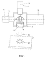
Figure 1 is a schematic front view of the laser writing device, being shown in a use condition thereof; -
Figure 2 is a front, partially cross-sectioned view, of the device; -
Figure 3 is a top plan view, as partially cross-sectioned, of the device; -
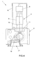
Figure 4 is a partially cross-sectioned side view of the device; -
Figure 5 is an exploded view of the device; -
Figure 6 is a cross-sectioned side view of a clamping flange; -
Figure 7 is a top plan view of a clamping flange; -
Figure 8 is a cross-sectioned side view of the focal lens; -
Figure 9 is a top plan view of the focal lens; -
Figure 10 is a cross-sectioned side view of a support assembly; -
Figure 11 is a top plan view of the support assembly; -
Figure 12 is a cross-sectioned front view of a device central box or casing; -
Figure 13 is a further cross-sectioned view of the device box or casing; -
Figure 14 is yet another cross-sectioned view of the device box or casing; -
Figure 15 is a top plan view of the device cover; and -
Figure 16 is a side view of the device cover. - With reference to the number references of the above mentioned figures, the laser writing device, according to the present invention, which has been generally indicated by the
reference number 1, comprises a printing head including a mirror driving system, for deflecting a laser beam by means of motor assemblies of a kinetic energy recovery type. - More specifically, the printing head comprises a box or
casing 2 having acasing cover 3 thereon two motor assemblies, respectively indicated by thereference numbers casing 6 and 7, are mounted. - Each said
motor assembly main motor 8, controlled by an information system (software) and a slave or "secondary"motor 9, for recovering the revolution kinetic energy, and operating as a braking or friction system for the main motor. - The
main motor 8 comprises a precisionrevolution reducing unit 10. - Advantageously, said
precision reducing unit 10 has a 1/16 or 1/32 reduction ratio, allowing to achieve a high operation precision. - The
motor assemblies casing 2 in an asymmetric manner with respect to one another. - In particular, the
motor assembly 4 is vertically mounted, according to an axis Y, by aclamping flange 11. - The
motor assembly 5 is in turn horizontally mounted according to an axis X, also by a clamping flange 12, with an addition ofspacer elements 14. - A
vertical mirror 15 is clamped to therevolution reducing unit 10 of thevertical motor assembly 4. - The
vertical mirror 15 deflects the laser beam onto ahorizontal mirror 16. - Said
horizontal mirror 16 is clamped to therevolution reducing unit 10 of thehorizontal motor assembly 5, through asupport element 17, for deflecting the laser beam onto afocal lens 18. - On the opposite side, with respect to the
horizontal motor assembly 5, of the central box orcasing 2, atube 19 is clamped and, through saidtube 19, the laser beam generated by alaser beam source 20 is directed. - On the opposite side, with respect to the
vertical motor assembly 4, of thecentral casing 2, asupport 21 is clamped including thefocal lens 18 with atightness gasket 22 arranged therebetween. - The laser writing device according to the present invention operates as follows.
- The
laser source 20 generates a laser beam which, through theprotective tube 19, arrives at thevertical mirror 15, mounted on the reducingunit 10 of thevertical motor assembly 4. - The
horizontal mirror 15 directs the laser beam onto thevertical mirror 16, mounted on the reducingunit 10 of thehorizontal motor assembly 5. - The
horizontal mirror 15 projects the laser beam onto thefocal lens 18, which in turn directs alaser beam 23 on asurface 24 to be processed. - The movements of the mirrors coupled to the
motor assemblies mirrors - The information system manages and controls the laser beam power, to drive the device to write on different surfaces.
- The device may be made of different materials, such as a plastic material, or a metal, glass, ceramics, carbon or any other desired materials of any desired nature providing the device with the above disclosed operating features.
- It has been found that the invention fully achieves the intended aim and objects.
- In fact, the invention has provided a laser writing device comprising a mirror driving system, for deflecting the laser beam, including motor assemblies with a kinetic energy recovery feature, thereby greatly reducing the making cost, by about 70%, with respect to conventional devices.
- Moreover, the inventive device provides the same performance as the much more expensive conventional like devices.
- In practicing the invention, the used materials, as well as the contingent size and shapes, can be any depending on requirements.
Claims (10)
- A laser writing device, characterized in that said device comprises a printing head including two motor assemblies asymmetrically clamped with respect to one another, said motor assemblies controlling a mirror driving system adapted to deflect a laser beam, said motor assemblies being of a kinetic energy recovery type.
- A laser writing device, according to claim 1, characterized in that said printing head comprises a casing, including a casing cover, and thereon the two motor assemblies, as protected by respective protecting box members, are mounted.
- A laser writing device, according to claim 1, characterized in that each said motor assembly comprises two motors: a main motor, operatively driven and controlled by an information system, and a secondary motor for recovering a revolution number, or kinetic energy, by operating as a braking or friction system for the main motor.
- A laser writing device, according to claim 3, characterized in that said main motor comprises a precision revolution reducing unit.
- A laser writing device, according to claim 4, characterized in that said revolution reducing unit has a 1/16 or 1/32 reduction ratio.
- A laser writing device, according to claim 1, characterized in that a said motor assembly is vertically mounted, according to an axis Y, by a clamping flange; the other said motor assembly being horizontally mounted, according to an axis X, by a further clamping flange, with an addition of spacer elements; a vertical mirror being clamped to the vertical motor assembly reducing unit.
- A laser writing device, according to one or more of the preceding claims, characterized in that said vertical mirror deflects the laser beam onto a horizontal mirror; said horizontal mirror being clamped to the horizontal motor assembly reducing unit by a support element, and deflecting the laser beam toward a focal lens.
- A laser writing device, according to claims 2 and 6, characterized in that, on a side of said central casing opposite to the horizontal motor assembly, a tube is clamped therethrough the laser beam generated by a laser beam source is directed.
- A laser writing device, according to one or more of the preceding claims, characterized in that on an opposite side, with respect to the vertical motor assembly, of the central casing, is clamped a support element containing the focal lens, with a tightness gasket arranged therebetween.
- A laser writing device, according to one or more of the preceding claims, characterized in that said device comprises an information system to control the movements of the mirrors clamped on the motor assembly reducing units.
Applications Claiming Priority (1)
| Application Number | Priority Date | Filing Date | Title |
|---|---|---|---|
| IT000012A ITVA20120012A1 (en) | 2012-05-15 | 2012-05-15 | MIRROR HANDLING SYSTEM FOR DEFLECTION OF A LASER BEAM BY MOTORS WITH KINETIC ENERGY RECOVERY. |
Publications (1)
| Publication Number | Publication Date |
|---|---|
| EP2664408A1 true EP2664408A1 (en) | 2013-11-20 |
Family
ID=46321386
Family Applications (1)
| Application Number | Title | Priority Date | Filing Date |
|---|---|---|---|
| EP13167791.6A Withdrawn EP2664408A1 (en) | 2012-05-15 | 2013-05-15 | Laser writing device |
Country Status (2)
| Country | Link |
|---|---|
| EP (1) | EP2664408A1 (en) |
| IT (1) | ITVA20120012A1 (en) |
Cited By (1)
| Publication number | Priority date | Publication date | Assignee | Title |
|---|---|---|---|---|
| CN118938443A (en) * | 2024-09-21 | 2024-11-12 | 苏州赛源光学科技有限公司 | A near-ultraviolet multi-band high-power direct writing lithography lens |
Citations (3)
| Publication number | Priority date | Publication date | Assignee | Title |
|---|---|---|---|---|
| WO2004082106A1 (en) * | 2003-03-13 | 2004-09-23 | Elop Electro-Optics Industries Ltd. | Torque producing device |
| JP2005007471A (en) * | 2003-06-16 | 2005-01-13 | Ricoh Unitechno Co Ltd | Method for controlling printing of laser marker |
| JP2009294380A (en) * | 2008-06-04 | 2009-12-17 | Canon Inc | Deflector, image forming apparatus and motor control circuit |
-
2012
- 2012-05-15 IT IT000012A patent/ITVA20120012A1/en unknown
-
2013
- 2013-05-15 EP EP13167791.6A patent/EP2664408A1/en not_active Withdrawn
Patent Citations (3)
| Publication number | Priority date | Publication date | Assignee | Title |
|---|---|---|---|---|
| WO2004082106A1 (en) * | 2003-03-13 | 2004-09-23 | Elop Electro-Optics Industries Ltd. | Torque producing device |
| JP2005007471A (en) * | 2003-06-16 | 2005-01-13 | Ricoh Unitechno Co Ltd | Method for controlling printing of laser marker |
| JP2009294380A (en) * | 2008-06-04 | 2009-12-17 | Canon Inc | Deflector, image forming apparatus and motor control circuit |
Cited By (1)
| Publication number | Priority date | Publication date | Assignee | Title |
|---|---|---|---|---|
| CN118938443A (en) * | 2024-09-21 | 2024-11-12 | 苏州赛源光学科技有限公司 | A near-ultraviolet multi-band high-power direct writing lithography lens |
Also Published As
| Publication number | Publication date |
|---|---|
| ITVA20120012A1 (en) | 2013-11-16 |
Similar Documents
| Publication | Publication Date | Title |
|---|---|---|
| KR102364197B1 (en) | Imaging optic for material machining by means of laser radiation and laser machining head having same | |
| US10688559B2 (en) | Three dimensional printer | |
| EP1751838B1 (en) | Selectively incrementally actuated linear eddy current braking system | |
| CN102581492A (en) | Laser etcher capable of automatically feeding roll materials | |
| US11175501B2 (en) | Display device, method for controlling display device, and moving body including display device | |
| CN208067567U (en) | Laser cutting system optical laser cutting head | |
| EP2664408A1 (en) | Laser writing device | |
| EP3766624A1 (en) | Laser light centering method and laser processing device | |
| US6678094B2 (en) | Apparatus for lettering or marking articles by means of a laser beam | |
| JP2019188455A (en) | Jig unit for laser beam axis confirmation and jig | |
| WO2008125173A3 (en) | Device and method for processing material by means of laser radiation | |
| CN103706944B (en) | Platform of ruling machine | |
| US10819963B2 (en) | Display device, method for controlling display device, program, recording medium, and moving body equipped with display device | |
| CN104889572A (en) | Laser engraving machine and operating method thereof | |
| CN1547055A (en) | A galvanometer laser scanning system | |
| CN204430557U (en) | A kind of laser beam automatic focusing mechanism | |
| US20170285327A1 (en) | Method for controlling position of a linear mems mirror with variable resolution and/or light intensity | |
| CN110508951A (en) | Anti-collision structure and method of a laser cutting head | |
| CN105171247B (en) | Cage type structure fully-sealed laser three-dimensional cutting head suitable for manipulator | |
| KR101682524B1 (en) | Slit width adjusting apparatus | |
| CN204997229U (en) | Laser processing system | |
| CN212384815U (en) | Laser cutting and carving mark integrated machine | |
| JP2015170571A (en) | Three-dimensional laminate molding apparatus and three-dimensional laminate molding method | |
| KR20200091994A (en) | An apparatus for laser machining and metheod for compensating error of the same | |
| JP2008229662A (en) | Laser processing apparatus and laser processing method |
Legal Events
| Date | Code | Title | Description |
|---|---|---|---|
| PUAI | Public reference made under article 153(3) epc to a published international application that has entered the european phase |
Free format text: ORIGINAL CODE: 0009012 |
|
| AK | Designated contracting states |
Kind code of ref document: A1 Designated state(s): AL AT BE BG CH CY CZ DE DK EE ES FI FR GB GR HR HU IE IS IT LI LT LU LV MC MK MT NL NO PL PT RO RS SE SI SK SM TR |
|
| AX | Request for extension of the european patent |
Extension state: BA ME |
|
| 17P | Request for examination filed |
Effective date: 20140515 |
|
| 17Q | First examination report despatched |
Effective date: 20190315 |
|
| STAA | Information on the status of an ep patent application or granted ep patent |
Free format text: STATUS: THE APPLICATION IS DEEMED TO BE WITHDRAWN |
|
| 18D | Application deemed to be withdrawn |
Effective date: 20191203 |