EP2664305A2 - Stent delivery and deployment system - Google Patents
Stent delivery and deployment system Download PDFInfo
- Publication number
- EP2664305A2 EP2664305A2 EP13168451.6A EP13168451A EP2664305A2 EP 2664305 A2 EP2664305 A2 EP 2664305A2 EP 13168451 A EP13168451 A EP 13168451A EP 2664305 A2 EP2664305 A2 EP 2664305A2
- Authority
- EP
- European Patent Office
- Prior art keywords
- stent
- catheter shaft
- catheter
- tubular structure
- deployment
- Prior art date
- Legal status (The legal status is an assumption and is not a legal conclusion. Google has not performed a legal analysis and makes no representation as to the accuracy of the status listed.)
- Granted
Links
Images




Classifications
-
- A—HUMAN NECESSITIES
- A61—MEDICAL OR VETERINARY SCIENCE; HYGIENE
- A61F—FILTERS IMPLANTABLE INTO BLOOD VESSELS; PROSTHESES; DEVICES PROVIDING PATENCY TO, OR PREVENTING COLLAPSING OF, TUBULAR STRUCTURES OF THE BODY, e.g. STENTS; ORTHOPAEDIC, NURSING OR CONTRACEPTIVE DEVICES; FOMENTATION; TREATMENT OR PROTECTION OF EYES OR EARS; BANDAGES, DRESSINGS OR ABSORBENT PADS; FIRST-AID KITS
- A61F2/00—Filters implantable into blood vessels; Prostheses, i.e. artificial substitutes or replacements for parts of the body; Appliances for connecting them with the body; Devices providing patency to, or preventing collapsing of, tubular structures of the body, e.g. stents
- A61F2/95—Instruments specially adapted for placement or removal of stents or stent-grafts
- A61F2/962—Instruments specially adapted for placement or removal of stents or stent-grafts having an outer sleeve
- A61F2/966—Instruments specially adapted for placement or removal of stents or stent-grafts having an outer sleeve with relative longitudinal movement between outer sleeve and prosthesis, e.g. using a push rod
-
- A—HUMAN NECESSITIES
- A61—MEDICAL OR VETERINARY SCIENCE; HYGIENE
- A61F—FILTERS IMPLANTABLE INTO BLOOD VESSELS; PROSTHESES; DEVICES PROVIDING PATENCY TO, OR PREVENTING COLLAPSING OF, TUBULAR STRUCTURES OF THE BODY, e.g. STENTS; ORTHOPAEDIC, NURSING OR CONTRACEPTIVE DEVICES; FOMENTATION; TREATMENT OR PROTECTION OF EYES OR EARS; BANDAGES, DRESSINGS OR ABSORBENT PADS; FIRST-AID KITS
- A61F2/00—Filters implantable into blood vessels; Prostheses, i.e. artificial substitutes or replacements for parts of the body; Appliances for connecting them with the body; Devices providing patency to, or preventing collapsing of, tubular structures of the body, e.g. stents
- A61F2/95—Instruments specially adapted for placement or removal of stents or stent-grafts
-
- A—HUMAN NECESSITIES
- A61—MEDICAL OR VETERINARY SCIENCE; HYGIENE
- A61F—FILTERS IMPLANTABLE INTO BLOOD VESSELS; PROSTHESES; DEVICES PROVIDING PATENCY TO, OR PREVENTING COLLAPSING OF, TUBULAR STRUCTURES OF THE BODY, e.g. STENTS; ORTHOPAEDIC, NURSING OR CONTRACEPTIVE DEVICES; FOMENTATION; TREATMENT OR PROTECTION OF EYES OR EARS; BANDAGES, DRESSINGS OR ABSORBENT PADS; FIRST-AID KITS
- A61F2/00—Filters implantable into blood vessels; Prostheses, i.e. artificial substitutes or replacements for parts of the body; Appliances for connecting them with the body; Devices providing patency to, or preventing collapsing of, tubular structures of the body, e.g. stents
- A61F2/95—Instruments specially adapted for placement or removal of stents or stent-grafts
- A61F2/9522—Means for mounting a stent or stent-graft onto or into a placement instrument
Definitions
- the invention relates to the field of delivery and deployment systems for implantable stents.
- stent devices when deployed and implanted provide support to tubular body conduits such as blood vessels or biliary ducts.
- the stent delivery system including the loaded stent device offers good flexibility in bending, in order that the stent and delivery system are able to negotiate tortuous anatomy en route to the desired implantation site.
- Flexible stents may also be axially compressible and consequently vulnerable to inadvertent axial shortening when deployed resulting from the action of the stent delivery system during deployment.
- Some delivery systems impart an axially compressive force to the stent during the deployment process, which can result in undesirable axial shortening of the stent.
- Some stent designs are particularly vulnerable to this effect.
- Expandable stent devices include stents and stent-grafts, the latter being a stent frame provided with a covering of graft material over the otherwise open interstices that exist between adjacent elements of the stent frame.
- Typical graft materials are flexible and usually are poiymeric materials such as polyethylene terephthalate (Dacron) fabric or porous expanded polytetrafluoroethylene (ePTFE).
- Expandable stent devices also include vena cava filters and any other devices that may be delivered through a body conduit to a site where it is desired to implant the device.
- expandable devices are typically removably affixed to a distal end of a flexible catheter that constitutes the basis of the delivery system, the catheter being the means by which the stent device is moved through the body conduit.
- the stent device is provided in a diametrically compacted state to enable it to be transported through the body conduit. Deployment at the desired site entails diametrical expansion of the stent device until it interferably contacts the luminal surface of the body conduit. The interference fit of the device against the wall of the body conduit results in implantation of the device at that site, either temporarily for some devices that are designed to be removable, or permanently.
- the diametrical expansion of the device also frees it from the distal end of the catheter-based delivery system, which is usually withdrawn from the body conduit immediately following conclusion of the deployment process.
- Expandable stent devices are typically either balloon expandable or self-expanding. Both types benefit from flexible delivery systems that allow them to be routed through tortuous anatomy. In particular, self-expanding stents are vulnerable to undesirable length change as the stent is released from its constrained small introductory diameter to its full deployed diameter. An effective, flexible delivery system that minimizes deployment force and minimizes any adverse effect on the length of the stent device would be of significant benefit to practitioners and patients.
- a stent delivery and deployment system is described, primarily for use with self-expanding stents. It is particularly useful for stents that are axially compliant (in the longitudinal direction, parallel to the longitudinal axis) and are vulnerable to undesirable foreshortening or lengthening during deployment, as the present system minimizes the risk of undesirable length change. Many of these axially compliant stents include flexibly connected adjacent stent elements; an example is a stent described in US Patent 5,507,767 to Maeda et al .
- deployment of a compacted stent from the small, compacted diameter necessary for delivery to the larger, deployed diameter substantially preserves the longitudinally oriented distance between adjacent stent elements of axially compliant stents such as stents having flexibly connected adjacent stent elements.
- the present system also reduces the force required of the practitioner to cause deployment due to the use of an everted traction tube with a separate constraining sheath. This also allows for the practical, easy deployment of longer length, small diameter stents, e.g., 6mm diameter stents of 70mm length or greater.
- the distal end of the system is the end that the stent device is affixed to and the first portion of the system to be inserted into a patient, while the opposite proximal end is typically provided with a catheter hub and includes the necessary aspects to allow the practitioner to control the device delivery and deployment.
- the system incorporates a traction tube (i.e., a tubular sheath) extending over the length of a diametrically constrained stent and everted back over itself, with the outer everted portion of the traction tube extending toward the proximal end of the delivery system.
- a traction tube i.e., a tubular sheath
- This proximal extension of the traction tube allows tension to be applied to the traction tube by a practitioner when it is desired to deploy the constrained stent.
- a tubular constraining sleeve (or constraining sheath) is provided between the inner portion and outer, everted portion of the traction tube for retaining the stent in its diametrically compacted state, the constraining sheath preferably extending over the length of the stent and maintaining it in a constrained state prior to deployment.
- the application of tension to the proximal end of the traction tube causes the constraining sheath to move in a proximal direction, freeing the constrained stent as it moves and allowing the stent to deploy against the wall of the body conduit within which it is located during the deployment process.
- the constraining sheath is preferably made from a thin, relatively flexible material and is provided in a tubular form possessed of sufficient hoop strength to maintain the stent in a diametrically compacted state as necessary for transport through the length of a body conduit to the desired implant location.
- the tubular constraining sheath is located between the inner portion of the traction tube that coaxially surrounds the compacted stent device and is in direct contact with the device, and the outer portion of the traction tube that is everted back over the outer surface of the constraining sheath. This everted portion of the traction tube preferably extends proximally along the length of the delivery catheter shaft back to the catheter hub where it is accessible to the practitioner.
- this arrangement provides an effective way to allow the constraining sheath to be moved proximally off of the compacted stent device beginning with the distal end of the device and progressing to the proximal end.
- the everted arrangement of the traction tube allows it to operate in similar fashion to the movement of the tracks of a tracked vehicle (e.g., a bulldozer), with the inner portion of the traction tube that surrounds the compacted stent device remaining stationary with respect to the device and consequently not imparting any axial compressive or extensive force to the device during deployment.
- the tension applied by the practitioner to the proximal end of the traction tube causes the inner portion of the traction tube to progressively evert over the distal end of the now-moving constraining sheath and consequently evert around to the outer surface of the constraining sheath as the stent device is progressively released in a proximal direction.
- the traction tube should be comprised of a strong, thin, flexible and lubricious material.
- a preferred material is ePTFE.
- the inside diameter of the traction tube is larger than the inside diameter of the constraining sheath. This arrangement allows the entire diametrical force from a constrained stent device to be contained by the constraining sheath and avoids the application of hoop stress to the traction tube.
- the thinness and flexibility of the traction tube allows the inner portion of that everted tube to be located inside of the constraining sheath in spite of the smaller inside diameter of the constraining sheath.
- the smaller inside diameter of the constraining sheath ensures that the traction tube is essentially only exposed to the tensile force applied by the practitioner during deployment and as such minimizes the tensile force that is required to cause deployment.
- the present system may also be used to advantage in the delivery and deployment of stent-grafts.
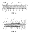
- Figure 1A shows a longitudinal cross section of the distal end of the delivery and deployment system 10 describing a stent device 12 mounted on the distal end of a delivery catheter shaft 13 having a lumen that may accommodate passage of a guidewire (not shown).
- the distal end of system 10 is indicated by arrow 23, while the proximal end is indicated by arrow 25.
- Stent device 12 preferably a self-expanding stent device, is in a compacted state (prior to deployment) and is contained within a constraining sheath 14 that is located between an inner portion 18 of a traction tube 16, and an outer portion 19 of the traction tube 16 that is everted back over the outer surface of the constraining sheath 14.
- Delivery catheter shaft 13 is, in this embodiment, supported exteriorly by supporting catheter shaft 21, the distal end of which abuts the proximal end of stent device 12 and provides a stop to help maintain the location of the stent device 12 at the distal end of delivery catheter shaft 13 during deployment.
- the combination of delivery catheter shaft 13 and supporting catheter shaft 21 provides system 10 with good 'pushability' to aid in insertion of the system through body conduits such as the vasculature.
- the combined delivery catheter shaft 13 and support catheter shaft 21 provide good compression resistance and column strength appropriate to enable deployment as will be further described, with appropriate flexibility to allow the combined catheter shafts to bend as necessary to follow bends in the body conduit during delivery of stent device 12 to the desired site.
- Traction tube 16 is a thin-walled, lubricious tube with good axial strength properties.
- Constraining sheath 14 is, in comparison, a more rigid tubular structure with appropriate flexibility in bending that allows the delivery system 10 to navigate tortuous vascular systems. It has sufficient hoop strength to maintain a self-expanding stent device 12 in a compacted state for prolonged periods as necessary to meet shelf life requirements.
- Constraining sheath 14 has an inside diameter of dimension appropriate for the diameter of the compacted stent device 12; this inside diameter is smaller than the inside diameter of the traction tube 16 in order that the hoop stress from a compacted self-expanding stent device 12 is contained entirely by the constraining sheath 14 and not by the traction tube 16.
- a recommended method of measuring the inside diameter of the flexible traction tube 16 is by gently fitting the tube over the end of a tapered mandrel provided with diameter graduations and noting the indicated diameter when the tube fits snugly about the diameter of the mandrel without forcing it further up the tapered mandrel.
- the tapered mandrel is a convenient method of measuring the inside diameter of the more rigid constraining sheath 14 as well. These inside diameters are determined for each of these tubular components as individual parts, separate from the assembled stent delivery and deployment system 10.
- Figure 1B is a subsequent longitudinal cross sectional view of the system of Figure 1A showing the progressive deployment of a self-expanding stent device 12 resulting from the application of tension (indicated by arrows 27) to the proximal end of the traction tube 16.
- the figure illustrates how the application of tension (indicated by arrows 27) to the proximal end of traction tube 16 causes the distal end of traction tube 16 to evert (as indicated by arrows 29) around the distal end of constraining sheath 14, moving the constraining sheath 14 in a proximal direction and progressively releasing the constrained stent device 12.
- Figures 2A and 2B are longitudinal cross sections of alternative embodiments similar to those of Figures 1A and 1B , differing only in that the support catheter shaft 21 is omitted.
- delivery catheter shaft 13 possesses the necessary physical characteristics to allow it to negotiate the vasculature during delivery of the stent device 12 to the desired site of implantation.
- Stent device 12 is sufficiently compacted around the outer surface of the distal end of delivery catheter shaft 13 that it is able to maintain its position on the distal end of delivery catheter shaft 13 during the deployment process.
- Figures 3A and 3B are also longitudinal cross sections of alternative embodiments similar to those of Figures 1A and 1B , differing only in that the support catheter shaft 21 is omitted and replaced by stop 26.
- Stop 26 is an annular component crimped to the outer surface of delivery catheter shaft 13 in abutting relationship to the proximal end of stent device 12, allowing stop 26 to hold the stent device 12 in position relative to the outer surface of delivery catheter shaft 13 without risk of inadvertent movement during the application of tension (arrow 27) to traction tube 16.
- FIG. 1A-3B utilize a traction tube 16 that extends for the full length of the system 10 wherein tension (indicated by arrows 27) is applied to traction tube 16 by the practitioner at the proximal end of system 10.
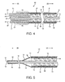
- the traction tube 16 may extend only beyond the proximal end of stent device 12, where it is attached at region 73 (by, for example, bonding with an adhesive such as cyanoacrylate) to another catheter shaft (actuator catheter shaft 71) that is coaxial about and axially movable with respect to the outer surface of the delivery catheter shaft 13 (and supporting catheter 21 if used).
- This actuator catheter shaft 71 is moved proximally with respect to system 10 (as indicated by arrows 27) in order to apply tension to traction tube 16 to initiate deployment of stent device 12.
- Traction tube 16 is to be made of thin, flexible, lubricious and suitably strong materials.
- a tube made from ePTFE is preferred.
- a preferred construction for the tube involves the use of ePTFE film having a predominately uniaxial microstructure. One or two layers of this film are first laid up on a mandrel of diameter and length suitable for the dimensions of the traction tube, with the high strength orientation of the film parallel to the longitudinal axis of the mandrel.
- a helical wrap of ePTFE tape is then wrapped around the underlying longitudinal layers, preferably with the helical wrap applied in two passes at two opposing pitch angles. In this fashion, the resulting tube is provided with good axial strength and good hoop strength.
- the multi-layered tube may be thermally bonded together by placing into an oven for a suitable time and temperature (e.g., in a convection oven set at 380°C for about 8 minutes).
- a suitable time and temperature e.g., in a convection oven set at 380°C for about 8 minutes.
- the helically wrapped film may be provided with a discontinuous or continuous coating of fluorinated ethylene propylene (FEP) on the inner surface of the film as taught by US Patent 5,810,870 .
- FEP fluorinated ethylene propylene
- traction tube may be made without the longitudinally oriented ePTFE film, using only the helically wrapped film.
- This construction allows the traction tube to extend in length under tension, and to reduce in diameter (i.e., to "neck” under tension). The diameter reduction causes the traction tube to fit very closely around the delivery catheter shaft 13.
- the resulting interference fit (lack of diametrical clearance) between the inner surface of the traction tube and the outer surface of the delivery catheter shaft enhances the precision of operation and stent deployment.
- a lubricant is provided between the traction tube and the delivery catheter shaft. This embodiment is described by the longitudinal cross section of Figure 5 and may, for example, be used advantageously with embodiments generally described in Figures 1A-3B .
- the constraining sheath may be of various polymeric materials with polyimide preferred.
- the catheter shaft(s) may be any material with suitable mechanical characteristics, with some preference for polyimide/braid/Pebax® composites.
- the stent delivery and deployment system 10 is made by first compacting and loading a stent 12 into the traction tube 16.
- Figure 6A shows a longitudinal cross section of a funnel device 80.
- the funnel is made with about a 15° taper and may be made of various materials including metals and plastics. Delrin® is a preferred plastic.
- a loading sleeve 82 is fitted into the small diameter end of funnel 80, with the inside diameter of the loading sleeve 82 matching the smallest inside diameter of funnel 80.
- the loading sleeve 82 should be of metal tubing (e.g., stainless steel) having a minimal wall thickness.
- FIG. 6B shows a longitudinal cross section of funnel 80 in use compacting a stent 12 to allow stent 12 to be fitted into traction tube 16.
- Traction tube 16 is fitted over the outer surface of loading tube 82, with the entire length of traction tube axially compressed ("scrunched") onto the outer surface of the relatively short loading tube 82.
- the axially compressed traction tube 16 assumes a corrugated appearance as a result of the axial compression.
- Stent 12 is pulled into funnel 80 by the application of tension (indicated by arrow 86) to loading fibers 84 which are temporarily attached (tied) to one end of stent 12.
- tension indicated by arrow 86
- iris-type stent compacting machines are available; one type is shown in US Patent 6,629,350 .
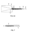
- Figure 7 shows a longitudinal cross section of compacted stent 12 captured within one end of traction tube 16, with the other end of traction tube 16 extending beyond the compacted stent 12.
- Loading fibers 84 have been removed from the end of compacted stent 12 to which they were previously attached, i.e., the end of compacted stent 12 that is adjacent to the end of traction tube 16.
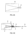
- a second funnel 81 shown in the longitudinal cross section of Figure 8A , is used to assemble the compacted stent 12 and traction tube 16 (as shown in Figure 7 ) into constraining sheath 14.
- the constraining sheath 14 of length appropriate for stent 12 is temporarily fitted into a bore at the small diameter end of funnel 81.
- the inside diameter of constraining sheath 14 corresponds with the smallest diameter of funnel 81 and is aligned with that diameter as shown by Figure 8A .
- This inside diameter is somewhat smaller that the smallest inside diameter of the first funnel 80 used to initially compact stent 12 for capture within traction tube 16. Again, the inside diameter of constraining sheath 14 is smaller than the inside diameter of traction tube 16.
- the extended end of traction tube 16 that is opposite the end containing stent 12 is inserted into the large diameter end of funnel 81 and on through the small diameter end and through the constraining sheath 14 until it emerges from the opposite end of constraining sheath 14.
- a length of catheter shaft 13 is inserted through stent 12 and traction tube 16 until it reaches slightly beyond the end of stent 12.
- Tension is applied to the emerged end of traction tube 16 (as indicated by arrows 86), thereby pulling stent 12 and the opposite end of traction tube 16 into constraining sheath 14, while maintaining the positional relationship of the ends of delivery catheter shaft 13 and stent 12.
- the progression of this process further compacts stent 12 onto the outer surface of delivery catheter shaft 13 while introducing stent 12 and traction tube 16 into constraining sheath 14, as shown in Figure 8B .
- Figure 9A is a longitudinal cross section that shows the result of the completed ioading process involving the second funnel 81.
- Stent 12 is compacted onto the outer surface of one end of delivery catheter shaft 13, and compacted stent 12 with traction tube 16 are captured coaxially within constraining sheath 14.
- the free end of traction tube 16 is everted over the outer surface of constraining sheath 14, appearing as shown in the longitudinal cross section of Figure 9B following conclusion of the full eversion of the free length of traction tube 16.
- a traction tube was formed from a thin film thickness (less than 0.025mm) of ePTFE.
- the film had a bulk density of approximately .5 grams/cc and an approximate fibril length of about 50 microns, and had been expanded along its length with the predominant strength direction falling parallel to the length of the film.
- Three layers of this film were wrapped around a stainless steel mandrel having a diameter of 3mm, with the length of the film parallel to the longitudinal axis of the mandrel.
- Another length of this film was provided with a discontinuous coating of FEP as taught by US Patent 5,810,870 , and then cut to a narrow width to create a tape about 12.5mm wide.
- a length of this tape was helically wrapped around the mandrel provided with the previously applied longitudinally oriented film layers, with each successive wrap overlapping half of the width of the previous wrap.
- the FEP coating faced the surface of the mandrel.
- a second helical wrap was applied in the same manner starting at the opposite end of the mandrel from the beginning of the first helical wrap.
- the mandrel and film were then heated in a convection oven set at 380°C for approximately 8 minutes to bond the film layers together, after which the film tube was stripped from the mandrel.
- the resulting traction tube was about 2.5 times the length of the stent that was intended to be subsequently loaded.
- the constraining sheath was a commercially available tube (MicroLumen Inc., Tampa FL 33614, part no. Sheath 0.0735 X 0.0795) having an inside diameter of 1.88mm and an outside diameter of 2.01mm.
- the tube was constructed with an inner liner of polyimide, stainless steel wire braid reinforcement and a polyether block amide outer layer.
- the delivery catheter shaft was a length of commercially available catheter tubing (High Performance Conductors, Inc, product identity .0220" Polyimide/Braid/Pebax® 5D Tubes, .0030 inch wall, M.G., Inman SC 29349) having an inside diameter of 0.56mm and an outside diameter of 0.71mm.
- the tube is constructed with an inner liner of polyimide, stainless steel wire braid reinforcement and a polyether block amide outer layer.
- the proximal end of the distal shaft and traction tube were bonded to a compressively rigid catheter component (a polyimide tube with braided stainless steel wire reinforcement (0.79mm inside diameter and 1.09mm outside diameter) with a cyanoacrylate adhesive.
- the everted portion of the traction tube was similarly bonded to a second, translatable catheter component (inside diameter 1.32mm and outside diameter 1.51mm, MicroLumen Inc., Tampa FL 33614, part no. 520-III 75) positioned coaxial to the first.
- Deployment of the stent was accomplished by applying opposing forces to the two catheter components, which then tensioned the traction tube, smoothly retracting the constraining sheath and deploying the stent.
Landscapes
- Health & Medical Sciences (AREA)
- Engineering & Computer Science (AREA)
- Biomedical Technology (AREA)
- Life Sciences & Earth Sciences (AREA)
- Oral & Maxillofacial Surgery (AREA)
- Transplantation (AREA)
- Heart & Thoracic Surgery (AREA)
- Vascular Medicine (AREA)
- Cardiology (AREA)
- Animal Behavior & Ethology (AREA)
- General Health & Medical Sciences (AREA)
- Public Health (AREA)
- Veterinary Medicine (AREA)
- Media Introduction/Drainage Providing Device (AREA)
- Prostheses (AREA)
- Materials For Medical Uses (AREA)
Abstract
Description
- The invention relates to the field of delivery and deployment systems for implantable stents.
- The accurate delivery and deployment of expandable medical devices such as stent devices remains a significant challenge to medical practitioners. These stent devices when deployed and implanted provide support to tubular body conduits such as blood vessels or biliary ducts. Preferably, the stent delivery system including the loaded stent device offers good flexibility in bending, in order that the stent and delivery system are able to negotiate tortuous anatomy en route to the desired implantation site. Flexible stents may also be axially compressible and consequently vulnerable to inadvertent axial shortening when deployed resulting from the action of the stent delivery system during deployment. Some delivery systems impart an axially compressive force to the stent during the deployment process, which can result in undesirable axial shortening of the stent. Some stent designs are particularly vulnerable to this effect.
- Expandable stent devices include stents and stent-grafts, the latter being a stent frame provided with a covering of graft material over the otherwise open interstices that exist between adjacent elements of the stent frame. Typical graft materials are flexible and usually are poiymeric materials such as polyethylene terephthalate (Dacron) fabric or porous expanded polytetrafluoroethylene (ePTFE). Expandable stent devices also include vena cava filters and any other devices that may be delivered through a body conduit to a site where it is desired to implant the device. These expandable devices are typically removably affixed to a distal end of a flexible catheter that constitutes the basis of the delivery system, the catheter being the means by which the stent device is moved through the body conduit. The stent device is provided in a diametrically compacted state to enable it to be transported through the body conduit. Deployment at the desired site entails diametrical expansion of the stent device until it interferably contacts the luminal surface of the body conduit. The interference fit of the device against the wall of the body conduit results in implantation of the device at that site, either temporarily for some devices that are designed to be removable, or permanently. The diametrical expansion of the device also frees it from the distal end of the catheter-based delivery system, which is usually withdrawn from the body conduit immediately following conclusion of the deployment process.
- Expandable stent devices are typically either balloon expandable or self-expanding. Both types benefit from flexible delivery systems that allow them to be routed through tortuous anatomy. In particular, self-expanding stents are vulnerable to undesirable length change as the stent is released from its constrained small introductory diameter to its full deployed diameter. An effective, flexible delivery system that minimizes deployment force and minimizes any adverse effect on the length of the stent device would be of significant benefit to practitioners and patients.
- A stent delivery and deployment system is described, primarily for use with self-expanding stents. It is particularly useful for stents that are axially compliant (in the longitudinal direction, parallel to the longitudinal axis) and are vulnerable to undesirable foreshortening or lengthening during deployment, as the present system minimizes the risk of undesirable length change. Many of these axially compliant stents include flexibly connected adjacent stent elements; an example is a stent described in
US Patent 5,507,767 to Maeda et al . Using the present system, deployment of a compacted stent from the small, compacted diameter necessary for delivery to the larger, deployed diameter substantially preserves the longitudinally oriented distance between adjacent stent elements of axially compliant stents such as stents having flexibly connected adjacent stent elements. - The present system also reduces the force required of the practitioner to cause deployment due to the use of an everted traction tube with a separate constraining sheath. This also allows for the practical, easy deployment of longer length, small diameter stents, e.g., 6mm diameter stents of 70mm length or greater.
- For purposes of the present description, the distal end of the system is the end that the stent device is affixed to and the first portion of the system to be inserted into a patient, while the opposite proximal end is typically provided with a catheter hub and includes the necessary aspects to allow the practitioner to control the device delivery and deployment.
- The system incorporates a traction tube (i.e., a tubular sheath) extending over the length of a diametrically constrained stent and everted back over itself, with the outer everted portion of the traction tube extending toward the proximal end of the delivery system. This proximal extension of the traction tube allows tension to be applied to the traction tube by a practitioner when it is desired to deploy the constrained stent. A tubular constraining sleeve (or constraining sheath) is provided between the inner portion and outer, everted portion of the traction tube for retaining the stent in its diametrically compacted state, the constraining sheath preferably extending over the length of the stent and maintaining it in a constrained state prior to deployment. The application of tension to the proximal end of the traction tube causes the constraining sheath to move in a proximal direction, freeing the constrained stent as it moves and allowing the stent to deploy against the wall of the body conduit within which it is located during the deployment process.
- The constraining sheath is preferably made from a thin, relatively flexible material and is provided in a tubular form possessed of sufficient hoop strength to maintain the stent in a diametrically compacted state as necessary for transport through the length of a body conduit to the desired implant location. The tubular constraining sheath is located between the inner portion of the traction tube that coaxially surrounds the compacted stent device and is in direct contact with the device, and the outer portion of the traction tube that is everted back over the outer surface of the constraining sheath. This everted portion of the traction tube preferably extends proximally along the length of the delivery catheter shaft back to the catheter hub where it is accessible to the practitioner. When tension is applied to the proximal end of the traction tube by the practitioner, this arrangement provides an effective way to allow the constraining sheath to be moved proximally off of the compacted stent device beginning with the distal end of the device and progressing to the proximal end. The everted arrangement of the traction tube allows it to operate in similar fashion to the movement of the tracks of a tracked vehicle (e.g., a bulldozer), with the inner portion of the traction tube that surrounds the compacted stent device remaining stationary with respect to the device and consequently not imparting any axial compressive or extensive force to the device during deployment. As deployment progresses, the tension applied by the practitioner to the proximal end of the traction tube causes the inner portion of the traction tube to progressively evert over the distal end of the now-moving constraining sheath and consequently evert around to the outer surface of the constraining sheath as the stent device is progressively released in a proximal direction.
- The traction tube should be comprised of a strong, thin, flexible and lubricious material. A preferred material is ePTFE. It is preferred that the inside diameter of the traction tube is larger than the inside diameter of the constraining sheath. This arrangement allows the entire diametrical force from a constrained stent device to be contained by the constraining sheath and avoids the application of hoop stress to the traction tube. The thinness and flexibility of the traction tube allows the inner portion of that everted tube to be located inside of the constraining sheath in spite of the smaller inside diameter of the constraining sheath. The smaller inside diameter of the constraining sheath ensures that the traction tube is essentially only exposed to the tensile force applied by the practitioner during deployment and as such minimizes the tensile force that is required to cause deployment.
- The present system may also be used to advantage in the delivery and deployment of stent-grafts.
- Further embodiments are given by way of the following numbered clauses: -
- 1. A deployment system for a self expanding stent comprising an axially compliant self-expanding stent having a compacted, smaller diameter for delivery to a deployment site in a body conduit and a larger deployed diameter, said compacted stent having a length between opposing ends wherein at least a portion of said length is provided with a covering of a first portion of a length of a tubular sheath and wherein a second portion of the length of the tubular sheath is adjacent to the first portion of the length of the tubular sheath and the second portion of the length is everted back over the first portion of the length in coaxial relationship, and wherein a tubular constraining sleeve is interposed between the first and second portions of the tubular sheath.
- 2. A deployment system according to clause 1 wherein deployment is initiated by application of tension to one end of the tubular sheath.
- 3. A deployment system according to clause 1 wherein deployment of the stent results from the application of tension to the second length portion of the tubular sheath.
- 4. A deployment system according to clause 1 wherein said tubular sheath comprises porous expanded polytetrafluoroethylene.
- 5. A deployment system according to clause 4 wherein said tubular constraining sleeve comprises polyimide.
- 6. A deployment system according to clause 1 wherein said tubular constraining sleeve comprises polyimide.
- 7. A deployment system according to clause 1 wherein said stent is compacted onto a portion of an outer surface of a catheter shaft.
- 8. A deployment system according to clause 1 wherein said stent has flexibly connected adjacent stent elements.
- 9. A deployment system according to clause 1 wherein said tubular constraining sheath has a smaller inside diameter than said tubular sheath.
- 10. A deployment system for a self-expanding device, comprising:
- a self-expanding device compacted to a small diameter for delivery into a body conduit prior to deployment; and
- a first length portion of a first sheath covering at least a portion of said compacted stent; and
- a second sheath covering at least a portion of said first length portion of the first sheath; and
- a second length portion of the first sheath everted back over and covering at least a portion of said second sheath.
- 11. A deployment system according to
clause 10 wherein deployment of said device is initiated by application of tension to one end of the first sheath. - 12. A deployment system according to
clause 10 wherein deployment of the device results from the application of tension to the second length portion of the first sheath. - 13. A deployment system according to
clause 10 wherein said first sheath comprises porous expanded polytetrafluoroethylene. - 14. A deployment system according to
clause 13 wherein said second sheath comprises polyimide. - 15. A deployment system according to
clause 10 wherein said second sheath comprises polyimide. - 16. A deployment system according to
clause 10 wherein said device is compacted onto a portion of an outer surface of a catheter shaft. - 17. A deployment system according to
clause 10 wherein said device has flexibly connected adjacent device elements. - 18. A deployment system according to
clause 10 wherein said second sheath has a smaller inside diameter than said first sheath. - 19. A deployment system for a stent, comprising:
- a stent compacted to a small diameter for delivery into a body conduit prior to deployment; and
- a first length portion of a first tubular sheath coaxially surrounding at least a portion of said compacted stent; and
- a second tubular sheath coaxially surrounding at least a portion of said first length portion of the first tubular sheath; and
- a second length portion of the first tubular sheath everted back over and coaxially surrounding at least a portion of said second tubular sheath.
- 20. A deployment system according to
clause 19 wherein deployment is initiated by application of tension to one end of the first tubular sheath. - 21. A deployment system according to
clause 19 wherein deployment of the stent results from the application of tension to the second length portion of the first tubular sheath. - 22. A deployment system according to
clause 19 wherein said first tubular sheath comprises porous expanded polytetrafluoroethylene. - 23. A deployment system according to clause 22 wherein said second tubular sheath comprises polyimide.
- 24. A deployment system according to
clause 19 wherein said second tubular sheath comprises polyimide. - 25. A deployment system according to
clause 19 wherein said stent is compacted onto a portion of an outer surface of a catheter shaft. - 26. A deployment system according to
clause 19 wherein said stent has flexibly connected adjacent stent elements. - 27. A deployment system according to
clause 19 wherein said second tubular sheath has a smaller inside diameter than said first tubular sheath. - 28. A deployment system for a self-expanding stent, comprising a self expanding stent having a length and a having a compacted diameter prior to deployment;
a first tubular sheath having a first length portion that coaxially surrounds at least a portion of the length of said compacted stent; and
a second tubular sheath that coaxially surrounds at least a portion of the first length portion of the first tubular sheath and at least a portion of the length of the compacted stent; and
a second length portion of the first tubular sheath that everts back over and coaxially surrounds: at least a portion of the second tubular sheath, at least a portion of the first length portion of the first tubular sheath and at least a portion of the length of the compacted stent. - 29. A deployment system according to clause 28 wherein deployment is initiated by application of tension to one end of the first tubular sheath.
- 30. A deployment system according to clause 28 wherein deployment of the stent results from the application of tension to the second length portion of the first tubular sheath.
- 31. A deployment system according to clause 28 wherein said first tubular sheath comprises porous expanded polytetrafluoroethylene.
- 32. A deployment system according to clause 31 wherein said second tubular sheath comprises polyimide.
- 33. A deployment system according to clause 28 wherein said second tubular sheath comprises polyimide.
- 34. A deployment system according to clause 28 wherein said stent is compacted onto a portion of an outer surface of a catheter shaft.
- 35. A deployment system according to clause 28 wherein said stent has flexibly connected adjacent stent elements.
- 36. A deployment system according to clause 28 wherein said second tubular sheath has a smaller inside diameter than said first tubular sheath.
- 37. A deployment system for a self-expanding stent, comprising:
- a self-expanding stent having a smaller compacted diameter prior to deployment and a larger, expanded deployed diameter, said stent having opposing distal and proximal ends and a length therebetween;
- said deployment system comprising said stent provided at the smaller compacted diameter; and
- a first tubular sheath having first and second ends and a length therebetween, said first tubular sheath coaxially surrounding said compacted stent wherein the first end of said first tubular sheath is located at or near the proximal end of said compacted stent and a first portion of the length of said first tubular sheath extends to the distal end of said compacted stent; and
- a second tubular sheath coaxially surrounding the first portion of the length of the first tubular sheath and substantially all of the length of the compacted stent; and
- wherein a second portion of the length of the first tubular sheath is everted near the distal end of said compacted stent and extends back in a proximal direction, coaxially surrounding the second tubular sheath, the first portion of the length of the first tubular sheath and the length of the compacted stent.
- 38. A deployment system according to clause 37 wherein deployment is initiated by application of tension in the proximal direction to the first tubular sheath.
- 39. A deployment system according to clause 37 wherein deployment of the stent results from the application of tension in the proximal direction to the second portion of the first tubular sheath.
- 40. A deployment system according to clause 37 wherein said first tubular sheath comprises porous expanded polytetrafluoroethylene.
- 41. A deployment system according to clause 40 wherein said second tubular sheath comprises polyimide.
- 42. A deployment system according to clause 37 wherein said second tubular sheath comprises polyimide.
- 43. A deployment system according to clause 37 wherein said stent is compacted onto a portion of an outer surface of a catheter shaft.
- 44. A deployment system according to clause 37 wherein said stent has flexibly connected adjacent stent elements.
- 45. A deployment system according to clause 37 wherein said second tubular sheath has a smaller inside diameter than said first tubular sheath.
- 46. A deployment system for a self expanding stent comprising an axially compliant self-expanding stent having a compacted, smaller diameter for delivery to a deployment site in a body conduit and a larger deployed diameter, said compacted stent having a length between ends of the stent and having adjacent stent elements with a longitudinally oriented distance between each pair of adjacent stent elements, wherein deployment of said compacted stent from the smaller diameter to the larger diameter substantially preserves the longitudinally oriented distance between the adjacent stent elements.
- 47. A catheter system comprising a catheter shaft having an outside diameter coaxially surrounded by a tubular structure that has opposing ends and an inside diameter that is reduced when tension is applied between the opposing ends to produce an interference fit between the outside diameter of the catheter shaft and the inside diameter of the tubular structure, wherein the application of tension between the opposing ends of the tubular structure actuates a device located at one end of the catheter shaft.
- 48. A catheter system according to clause 47 wherein said tubular structure comprises porous expanded polytetrafluoroethylene.
- 49. A catheter system according to clause 48 wherein said tubular structure comprises helically wrapped tape.
- 50. A catheter system according to clause 47 wherein said tubular structure comprises helically wrapped tape.
-
-
Figure 1A is a longitudinal cross section of the distal end of the delivery system showing a compacted stent device contained within a constraining sheath that is located between an inner portion of a traction tube and an outer portion of the traction tube that is everted back over the outer surface of the constraining sheath. -
Figure 1B is a subsequent longitudinal cross sectional view of the system ofFigure 1 showing the application of tension to the proximal end of the traction tube, resulting in progressive deployment of the stent device. -
Figures 2A-5 are longitudinal cross sectional views showing alternative embodiments. -
Figure 6A is a longitudinal cross section showing a first funnel device for compacting and loading a stent into the traction tube. -
Figures 6B and6C are longitudinal cross sectional views showing a stent being compacted and loaded into a traction tube using the first funnel ofFigure 6A . -
Figure 7 shows a longitudinal cross section of a stent after being compacted and loaded into a traction tube. -
Figure 8A is a longitudinal cross section of a constraining sheath fitted to a second funnel device prior to loading of the stent and traction tube assembly. -
Figure 8B is a longitudinal cross section showing the stent and traction tube assembly ofFigure 7 being further compacted and loaded into the constraining sheath, along with a delivery catheter shaft, via the second funnel. -
Figure 9A shows a longitudinal cross section of the stent after compaction onto the delivery catheter shaft and after having been loaded into the traction tube and constraining sheath. -
Figure 9B shows a longitudinal cross section of the traction tube after the proximal end of the traction tube has been everted back over the outer surface of the constraining sheath. -
Figure 1A shows a longitudinal cross section of the distal end of the delivery anddeployment system 10 describing astent device 12 mounted on the distal end of adelivery catheter shaft 13 having a lumen that may accommodate passage of a guidewire (not shown). The distal end ofsystem 10 is indicated byarrow 23, while the proximal end is indicated byarrow 25.Stent device 12, preferably a self-expanding stent device, is in a compacted state (prior to deployment) and is contained within a constrainingsheath 14 that is located between aninner portion 18 of atraction tube 16, and anouter portion 19 of thetraction tube 16 that is everted back over the outer surface of the constrainingsheath 14. -
Delivery catheter shaft 13 is, in this embodiment, supported exteriorly by supportingcatheter shaft 21, the distal end of which abuts the proximal end ofstent device 12 and provides a stop to help maintain the location of thestent device 12 at the distal end ofdelivery catheter shaft 13 during deployment. The combination ofdelivery catheter shaft 13 and supportingcatheter shaft 21 providessystem 10 with good 'pushability' to aid in insertion of the system through body conduits such as the vasculature. The combineddelivery catheter shaft 13 andsupport catheter shaft 21 provide good compression resistance and column strength appropriate to enable deployment as will be further described, with appropriate flexibility to allow the combined catheter shafts to bend as necessary to follow bends in the body conduit during delivery ofstent device 12 to the desired site. -
Traction tube 16 is a thin-walled, lubricious tube with good axial strength properties. Constrainingsheath 14 is, in comparison, a more rigid tubular structure with appropriate flexibility in bending that allows thedelivery system 10 to navigate tortuous vascular systems. It has sufficient hoop strength to maintain a self-expandingstent device 12 in a compacted state for prolonged periods as necessary to meet shelf life requirements. Constrainingsheath 14 has an inside diameter of dimension appropriate for the diameter of the compactedstent device 12; this inside diameter is smaller than the inside diameter of thetraction tube 16 in order that the hoop stress from a compacted self-expandingstent device 12 is contained entirely by the constrainingsheath 14 and not by thetraction tube 16. - A recommended method of measuring the inside diameter of the
flexible traction tube 16 is by gently fitting the tube over the end of a tapered mandrel provided with diameter graduations and noting the indicated diameter when the tube fits snugly about the diameter of the mandrel without forcing it further up the tapered mandrel. The tapered mandrel is a convenient method of measuring the inside diameter of the more rigid constrainingsheath 14 as well. These inside diameters are determined for each of these tubular components as individual parts, separate from the assembled stent delivery anddeployment system 10. -
Figure 1B is a subsequent longitudinal cross sectional view of the system ofFigure 1A showing the progressive deployment of a self-expandingstent device 12 resulting from the application of tension (indicated by arrows 27) to the proximal end of thetraction tube 16. The figure illustrates how the application of tension (indicated by arrows 27) to the proximal end oftraction tube 16 causes the distal end oftraction tube 16 to evert (as indicated by arrows 29) around the distal end of constrainingsheath 14, moving the constrainingsheath 14 in a proximal direction and progressively releasing theconstrained stent device 12. As thetraction tube 16 everts and moves the constrainingsheath 14 in a proximal direction, it is seen how the remaining, not-yet-evertedinner portion 18 of thetraction tube 16 that is still in contact with the remaining constrained portion ofstent device 12, does not move with respect to the outer surface ofstent device 12, thereby avoiding any axial imposition of force to the remaining constrained portion ofstent device 12. This effect maximizes the uniform deployment ofstent device 12, allowing it to contact the luminal surface of the surrounding body conduit in an accurate manner without distortion (particularly axial distortion) of thestent device 12. - The application of tension (arrow 27) to the proximal end of
traction tube 16 to actuate deployment ofstent device 12 is made possible by the compression resistance ofdelivery catheter shaft 13 and supportingcatheter 21. -
Figures 2A and 2B are longitudinal cross sections of alternative embodiments similar to those ofFigures 1A and 1B , differing only in that thesupport catheter shaft 21 is omitted. In this embodiment,delivery catheter shaft 13 possesses the necessary physical characteristics to allow it to negotiate the vasculature during delivery of thestent device 12 to the desired site of implantation.Stent device 12 is sufficiently compacted around the outer surface of the distal end ofdelivery catheter shaft 13 that it is able to maintain its position on the distal end ofdelivery catheter shaft 13 during the deployment process. -
Figures 3A and 3B are also longitudinal cross sections of alternative embodiments similar to those ofFigures 1A and 1B , differing only in that thesupport catheter shaft 21 is omitted and replaced bystop 26.Stop 26 is an annular component crimped to the outer surface ofdelivery catheter shaft 13 in abutting relationship to the proximal end ofstent device 12, allowingstop 26 to hold thestent device 12 in position relative to the outer surface ofdelivery catheter shaft 13 without risk of inadvertent movement during the application of tension (arrow 27) totraction tube 16. - The embodiments described by
Figures 1A-3B utilize atraction tube 16 that extends for the full length of thesystem 10 wherein tension (indicated by arrows 27) is applied totraction tube 16 by the practitioner at the proximal end ofsystem 10. In another alternative described by the longitudinal cross section ofFigure 4 , thetraction tube 16 may extend only beyond the proximal end ofstent device 12, where it is attached at region 73 (by, for example, bonding with an adhesive such as cyanoacrylate) to another catheter shaft (actuator catheter shaft 71) that is coaxial about and axially movable with respect to the outer surface of the delivery catheter shaft 13 (and supportingcatheter 21 if used). Thisactuator catheter shaft 71 is moved proximally with respect to system 10 (as indicated by arrows 27) in order to apply tension totraction tube 16 to initiate deployment ofstent device 12. -
Traction tube 16 is to be made of thin, flexible, lubricious and suitably strong materials. A tube made from ePTFE is preferred. A preferred construction for the tube involves the use of ePTFE film having a predominately uniaxial microstructure. One or two layers of this film are first laid up on a mandrel of diameter and length suitable for the dimensions of the traction tube, with the high strength orientation of the film parallel to the longitudinal axis of the mandrel. A helical wrap of ePTFE tape is then wrapped around the underlying longitudinal layers, preferably with the helical wrap applied in two passes at two opposing pitch angles. In this fashion, the resulting tube is provided with good axial strength and good hoop strength. The multi-layered tube may be thermally bonded together by placing into an oven for a suitable time and temperature (e.g., in a convection oven set at 380°C for about 8 minutes). If desired, for easier thermal bonding of the layers, the helically wrapped film may be provided with a discontinuous or continuous coating of fluorinated ethylene propylene (FEP) on the inner surface of the film as taught byUS Patent 5,810,870 . - Alternatively, traction tube may be made without the longitudinally oriented ePTFE film, using only the helically wrapped film. This construction allows the traction tube to extend in length under tension, and to reduce in diameter (i.e., to "neck" under tension). The diameter reduction causes the traction tube to fit very closely around the
delivery catheter shaft 13. The resulting interference fit (lack of diametrical clearance) between the inner surface of the traction tube and the outer surface of the delivery catheter shaft enhances the precision of operation and stent deployment. Preferably, a lubricant is provided between the traction tube and the delivery catheter shaft. This embodiment is described by the longitudinal cross section ofFigure 5 and may, for example, be used advantageously with embodiments generally described inFigures 1A-3B . - The constraining sheath may be of various polymeric materials with polyimide preferred. Likewise, the catheter shaft(s) may be any material with suitable mechanical characteristics, with some preference for polyimide/braid/Pebax® composites.
- The stent delivery and
deployment system 10 is made by first compacting and loading astent 12 into thetraction tube 16.Figure 6A shows a longitudinal cross section of afunnel device 80. The funnel is made with about a 15° taper and may be made of various materials including metals and plastics. Delrin® is a preferred plastic. Aloading sleeve 82 is fitted into the small diameter end offunnel 80, with the inside diameter of theloading sleeve 82 matching the smallest inside diameter offunnel 80. Theloading sleeve 82 should be of metal tubing (e.g., stainless steel) having a minimal wall thickness. -
Figure 6B shows a longitudinal cross section offunnel 80 in use compacting astent 12 to allowstent 12 to be fitted intotraction tube 16.Traction tube 16 is fitted over the outer surface ofloading tube 82, with the entire length of traction tube axially compressed ("scrunched") onto the outer surface of the relativelyshort loading tube 82. The axially compressedtraction tube 16 assumes a corrugated appearance as a result of the axial compression.Stent 12 is pulled intofunnel 80 by the application of tension (indicated by arrow 86) toloading fibers 84 which are temporarily attached (tied) to one end ofstent 12. Asstent 12 progresses from the large diameter end offunnel 80 toward the small diameter end, it is diametrically compacted as shown. Continued application of tension toloading fibers 84 pulls the small end ofstent 12 through theloading tube 82. - While the use of a funnel device is described for stent compaction, there are alternative methods of compacting stents. For example, iris-type stent compacting machines are available; one type is shown in
US Patent 6,629,350 . - As the compacted
stent 12 begins to exit the end ofloading tube 82opposite funnel 80, the corresponding end of axially compressedtraction tube 16 is pushed off of the end ofloading tube 82 coaxially onto the outer surface of compactedstent 12. Continued application of tension and continued progression of compactedstent 12 out of the end ofloading tube 82 whiletraction tube 16 is simultaneously fed onto the outer surface of compactedstent 12 results in the compactedstent 12 being captured coaxially withintraction tube 16 as shown by the longitudinal cross section ofFigure 6C . -
Figure 7 shows a longitudinal cross section of compactedstent 12 captured within one end oftraction tube 16, with the other end oftraction tube 16 extending beyond the compactedstent 12.Loading fibers 84 have been removed from the end of compactedstent 12 to which they were previously attached, i.e., the end of compactedstent 12 that is adjacent to the end oftraction tube 16. - A
second funnel 81, shown in the longitudinal cross section ofFigure 8A , is used to assemble the compactedstent 12 and traction tube 16 (as shown inFigure 7 ) into constrainingsheath 14. The constrainingsheath 14 of length appropriate forstent 12 is temporarily fitted into a bore at the small diameter end offunnel 81. The inside diameter of constrainingsheath 14 corresponds with the smallest diameter offunnel 81 and is aligned with that diameter as shown byFigure 8A . This inside diameter is somewhat smaller that the smallest inside diameter of thefirst funnel 80 used to initiallycompact stent 12 for capture withintraction tube 16. Again, the inside diameter of constrainingsheath 14 is smaller than the inside diameter oftraction tube 16. - As shown by the longitudinal cross section of
Figure 8B , the extended end oftraction tube 16 that is opposite theend containing stent 12 is inserted into the large diameter end offunnel 81 and on through the small diameter end and through the constrainingsheath 14 until it emerges from the opposite end of constrainingsheath 14. A length ofcatheter shaft 13 is inserted throughstent 12 andtraction tube 16 until it reaches slightly beyond the end ofstent 12. Tension is applied to the emerged end of traction tube 16 (as indicated by arrows 86), thereby pullingstent 12 and the opposite end oftraction tube 16 into constrainingsheath 14, while maintaining the positional relationship of the ends ofdelivery catheter shaft 13 andstent 12. The progression of this processfurther compacts stent 12 onto the outer surface ofdelivery catheter shaft 13 while introducingstent 12 andtraction tube 16 into constrainingsheath 14, as shown inFigure 8B . -
Figure 9A is a longitudinal cross section that shows the result of the completed ioading process involving thesecond funnel 81.Stent 12 is compacted onto the outer surface of one end ofdelivery catheter shaft 13, and compactedstent 12 withtraction tube 16 are captured coaxially within constrainingsheath 14. Finally, the free end oftraction tube 16 is everted over the outer surface of constrainingsheath 14, appearing as shown in the longitudinal cross section ofFigure 9B following conclusion of the full eversion of the free length oftraction tube 16. - A traction tube was formed from a thin film thickness (less than 0.025mm) of ePTFE. The film had a bulk density of approximately .5 grams/cc and an approximate fibril length of about 50 microns, and had been expanded along its length with the predominant strength direction falling parallel to the length of the film. Three layers of this film were wrapped around a stainless steel mandrel having a diameter of 3mm, with the length of the film parallel to the longitudinal axis of the mandrel. Another length of this film was provided with a discontinuous coating of FEP as taught by
US Patent 5,810,870 , and then cut to a narrow width to create a tape about 12.5mm wide. A length of this tape was helically wrapped around the mandrel provided with the previously applied longitudinally oriented film layers, with each successive wrap overlapping half of the width of the previous wrap. The FEP coating faced the surface of the mandrel. A second helical wrap was applied in the same manner starting at the opposite end of the mandrel from the beginning of the first helical wrap. The mandrel and film were then heated in a convection oven set at 380°C for approximately 8 minutes to bond the film layers together, after which the film tube was stripped from the mandrel. The resulting traction tube was about 2.5 times the length of the stent that was intended to be subsequently loaded. - The constraining sheath was a commercially available tube (MicroLumen Inc., Tampa FL 33614, part no. Sheath 0.0735 X 0.0795) having an inside diameter of 1.88mm and an outside diameter of 2.01mm. The tube was constructed with an inner liner of polyimide, stainless steel wire braid reinforcement and a polyether block amide outer layer.
- The delivery catheter shaft was a length of commercially available catheter tubing (High Performance Conductors, Inc, product identity .0220" Polyimide/Braid/Pebax® 5D Tubes, .0030 inch wall, M.G., Inman SC 29349) having an inside diameter of 0.56mm and an outside diameter of 0.71mm. The tube is constructed with an inner liner of polyimide, stainless steel wire braid reinforcement and a polyether block amide outer layer.
- Loading of a Cordis S.M.A.R.T.® Stent (6mm deployed diameter, 80mm length; Cordis Corp., Miami Lakes FL 33014) was accomplished with a loading funnel as described above. After loading the stent into the traction tube, the tube extended beyond the stent approximately 1.5 times the stent length on one end and 2 cm on the other. A length of the delivery catheter shaft tubing was inserted into the lumen of the partially compressed stent. The traction tube was threaded through a second funnel and through the constraining sheath, also as described above. Tension was then applied to the traction-tube to pull the stent into the constraining sheath. The traction tube was then everted over the constraining sheath. The proximal end of the distal shaft and traction tube were bonded to a compressively rigid catheter component (a polyimide tube with braided stainless steel wire reinforcement (0.79mm inside diameter and 1.09mm outside diameter) with a cyanoacrylate adhesive. The everted portion of the traction tube was similarly bonded to a second, translatable catheter component (inside diameter 1.32mm and outside diameter 1.51mm, MicroLumen Inc., Tampa FL 33614, part no. 520-III 75) positioned coaxial to the first. Deployment of the stent was accomplished by applying opposing forces to the two catheter components, which then tensioned the traction tube, smoothly retracting the constraining sheath and deploying the stent.
- While the principles of the invention have been made clear in the illustrative embodiments set forth herein, it will be obvious to those skilled in the art to make various modifications to the structure, arrangement, proportion, elements, materials and components used in the practice of the invention. To the extent that these various modifications do not depart from the spirit and scope of the appended claims, they are intended to be encompassed therein.
Claims (15)
- A catheter system comprising a catheter shaft (13, 21) having an outside diameter coaxially surrounded by a tubular structure (16) that has opposing ends and an inside diameter that is reduced when tension is applied between the opposing ends to produce an interference fit between the outside diameter of the catheter shaft (13, 21) and the inside diameter of the tubular structure (16), wherein the application of tension between the opposing ends of the tubular structure (16) actuates a device (12) located at one end of the catheter shaft.
- A catheter system according to claim 1 wherein said tubular structure (16) comprises porous expanded polytetrafluoroethylene.
- A catheter system according to claim 1 or 2 wherein said tubular structure (16) comprises helically wrapped tape.
- A catheter system according to any of the claims 1, 2 or 3 wherein the system comprises a lubricant provided between the tubular structure (16) and the catheter shaft (13, 21).
- A catheter system according to any of the claims 1 to 4 wherein the device (12) located at one end of the catheter shaft comprises a stent device (12).
- A catheter system according to claim 5, wherein the stent device (12) comprising a self-expanding stent (12).
- A catheter system according to claim 5, wherein the stent device (12) comprising a vena cava filter.
- A catheter system according to any of the claims 1 to 8, wherein at least some of the tubular structure (16) extends over the length of the device (12), the device (12) being constrained diametrically, and the tubular structure (16) being everted back over itself, with the outer everted portion (16) of the tubular structure (16) extending towards the proximal end of the catheter system.
- A catheter system according to claim 8, wherein the system comprises a constraining sheath (14) provided between the inner portions (18) and outer, everted portion (16) of the tubular structure (16) for retaining the device (12) in its diametrically compacted state.
- A catheter system according to claim 9, wherein the constraining sheath (14) extends over the length of the device (12) and maintains the device (12) in its constrained state prior to deployment by actuation of the tubular structure (16).
- A catheter system according to claim 9 or 10, wherein said constraining sheath (14) comprises polyimide.
- A catheter system according to any of the claims 1 to 11, wherein said device (12) is compacted onto a portion of an outer surface of the catheter shaft (13).
- A catheter system according to any of the claims 1 to 12, wherein the catheter shaft (13, 21) comprises a supporting catheter shaft (21), which exteriorly supports a delivery catheter shaft (13), a distal end of the supporting catheter shaft (21) abutting the proximal end of the device (12).
- A catheter system according to any of the claims 1 to 13, wherein the catheter shaft comprises a delivery catheter shaft (13), and the system comprises a stop (26), provided on the outer surface of the delivery catheter shaft (13), and in abutting relationship with a proximal end of the device (12).
- A method of making a catheter system, comprising:(i) compacting and loading a device (12) into a tubular structure (16),(ii) inserting a catheter shaft (13) through the device (12) and tubular structure (16); and(iii) pulling the device (12) and the tubular structure (16) into a constraining sheath, while maintaining positional relationship of the ends of the catheter shaft (13) and the device (12).
Applications Claiming Priority (3)
| Application Number | Priority Date | Filing Date | Title |
|---|---|---|---|
| US11/745,347 US8764816B2 (en) | 2007-05-07 | 2007-05-07 | Stent delivery and deployment system |
| EP08767641.7A EP2144581B1 (en) | 2007-05-07 | 2008-05-05 | Stent delivery and deployment system |
| PCT/US2008/005866 WO2008137177A2 (en) | 2007-05-07 | 2008-05-05 | Stent delivery and deployment system |
Related Parent Applications (2)
| Application Number | Title | Priority Date | Filing Date |
|---|---|---|---|
| EP08767641.7A Division EP2144581B1 (en) | 2007-05-07 | 2008-05-05 | Stent delivery and deployment system |
| EP08767641.7A Division-Into EP2144581B1 (en) | 2007-05-07 | 2008-05-05 | Stent delivery and deployment system |
Publications (3)
| Publication Number | Publication Date |
|---|---|
| EP2664305A2 true EP2664305A2 (en) | 2013-11-20 |
| EP2664305A3 EP2664305A3 (en) | 2014-02-19 |
| EP2664305B1 EP2664305B1 (en) | 2019-10-23 |
Family
ID=39590508
Family Applications (2)
| Application Number | Title | Priority Date | Filing Date |
|---|---|---|---|
| EP13168451.6A Active EP2664305B1 (en) | 2007-05-07 | 2008-05-05 | Stent delivery and deployment system |
| EP08767641.7A Active EP2144581B1 (en) | 2007-05-07 | 2008-05-05 | Stent delivery and deployment system |
Family Applications After (1)
| Application Number | Title | Priority Date | Filing Date |
|---|---|---|---|
| EP08767641.7A Active EP2144581B1 (en) | 2007-05-07 | 2008-05-05 | Stent delivery and deployment system |
Country Status (7)
| Country | Link |
|---|---|
| US (1) | US8764816B2 (en) |
| EP (2) | EP2664305B1 (en) |
| JP (2) | JP2010526583A (en) |
| AU (1) | AU2008248074B2 (en) |
| CA (3) | CA2779456C (en) |
| ES (1) | ES2608685T3 (en) |
| WO (1) | WO2008137177A2 (en) |
Families Citing this family (47)
| Publication number | Priority date | Publication date | Assignee | Title |
|---|---|---|---|---|
| US8540760B2 (en) * | 2007-07-11 | 2013-09-24 | Cook Medical Technologies Llc | Tubular devices having reversible components for deployment of endoluminal occluders and related methods and systems |
| US8114147B2 (en) | 2008-06-16 | 2012-02-14 | Boston Scientific Scimed, Inc. | Continuous double layered stent for migration resistance |
| US20100249815A1 (en) * | 2009-03-25 | 2010-09-30 | Cook Incorporated | Everted sheath thrombectomy device |
| WO2011017189A1 (en) * | 2009-08-04 | 2011-02-10 | Wilson-Cook Medical Inc. | Roll sleeve mechanism for proximal release stent delivery device |
| US20110118817A1 (en) * | 2009-11-17 | 2011-05-19 | Boston Scientific Scimed, Inc. | Stent delivery system |
| AU2012209013B2 (en) * | 2011-08-02 | 2013-11-14 | Cook Medical Technologies Llc | Delivery device having a variable diameter introducer sheath |
| US10213329B2 (en) | 2011-08-12 | 2019-02-26 | W. L. Gore & Associates, Inc. | Evertable sheath devices, systems, and methods |
| US8621975B2 (en) * | 2011-09-20 | 2014-01-07 | Aga Medical Corporation | Device and method for treating vascular abnormalities |
| US9039752B2 (en) | 2011-09-20 | 2015-05-26 | Aga Medical Corporation | Device and method for delivering a vascular device |
| JP6057584B2 (en) * | 2012-07-24 | 2017-01-11 | 株式会社カネカ | Self-expanding stent delivery system and manufacturing method thereof |
| US10639179B2 (en) | 2012-11-21 | 2020-05-05 | Ram Medical Innovations, Llc | System for the intravascular placement of a medical device |
| US9907641B2 (en) | 2014-01-10 | 2018-03-06 | W. L. Gore & Associates, Inc. | Implantable intraluminal device |
| US9763819B1 (en) | 2013-03-05 | 2017-09-19 | W. L. Gore & Associates, Inc. | Tapered sleeve |
| JP6088304B2 (en) * | 2013-03-15 | 2017-03-01 | 株式会社カネカ | Method for manufacturing stent delivery system for self-expanding stent |
| US10966850B2 (en) * | 2014-03-06 | 2021-04-06 | W. L. Gore & Associates, Inc. | Implantable medical device constraint and deployment apparatus |
| US9539481B2 (en) * | 2014-06-11 | 2017-01-10 | Gisle Solhaug | Selectable weight assembly for golf clubs |
| US9636244B2 (en) * | 2015-04-09 | 2017-05-02 | Mubin I. Syed | Apparatus and method for proximal to distal stent deployment |
| US10327933B2 (en) * | 2015-04-28 | 2019-06-25 | Cook Medical Technologies Llc | Medical cannulae, delivery systems and methods |
| CN113384384A (en) * | 2015-06-29 | 2021-09-14 | 莱拉医药公司 | Stent loading and delivery system |
| US10327929B2 (en) | 2015-10-30 | 2019-06-25 | Ram Medical Innovations, Llc | Apparatus and method for stabilization of procedural catheter in tortuous vessels |
| US9980838B2 (en) | 2015-10-30 | 2018-05-29 | Ram Medical Innovations Llc | Apparatus and method for a bifurcated catheter for use in hostile aortic arches |
| US10492936B2 (en) | 2015-10-30 | 2019-12-03 | Ram Medical Innovations, Llc | Apparatus and method for improved access of procedural catheter in tortuous vessels |
| US10779976B2 (en) | 2015-10-30 | 2020-09-22 | Ram Medical Innovations, Llc | Apparatus and method for stabilization of procedural catheter in tortuous vessels |
| US11020256B2 (en) | 2015-10-30 | 2021-06-01 | Ram Medical Innovations, Inc. | Bifurcated “Y” anchor support for coronary interventions |
| US10881542B2 (en) | 2016-04-05 | 2021-01-05 | Boston Scientific Scimed, Inc. | Stent delivery device |
| US10173031B2 (en) | 2016-06-20 | 2019-01-08 | Mubin I. Syed | Interchangeable flush/selective catheter |
| DE102016012869A1 (en) | 2016-10-28 | 2018-05-03 | Protembis Gmbh | Embolic protection device, method for its folding and shaping device |
| US10653523B2 (en) | 2017-01-19 | 2020-05-19 | 4C Medical Technologies, Inc. | Systems, methods and devices for delivery systems, methods and devices for implanting prosthetic heart valves |
| US10561495B2 (en) | 2017-01-24 | 2020-02-18 | 4C Medical Technologies, Inc. | Systems, methods and devices for two-step delivery and implantation of prosthetic heart valve |
| EP3585305B1 (en) | 2017-02-23 | 2025-07-30 | Boston Scientific Scimed, Inc. | Medical drain device |
| US12029647B2 (en) | 2017-03-07 | 2024-07-09 | 4C Medical Technologies, Inc. | Systems, methods and devices for prosthetic heart valve with single valve leaflet |
| US12036113B2 (en) | 2017-06-14 | 2024-07-16 | 4C Medical Technologies, Inc. | Delivery of heart chamber prosthetic valve implant |
| CA3077748C (en) | 2017-10-11 | 2023-01-03 | W. L. Gore & Associates, Inc | Implantable medical device constraint and deployment apparatus |
| US10857014B2 (en) | 2018-02-18 | 2020-12-08 | Ram Medical Innovations, Llc | Modified fixed flat wire bifurcated catheter and its application in lower extremity interventions |
| US11857441B2 (en) | 2018-09-04 | 2024-01-02 | 4C Medical Technologies, Inc. | Stent loading device |
| US12544226B2 (en) | 2019-02-14 | 2026-02-10 | 4C Medical Technologies, Inc. | Hydrophilic skirt for paravalvular leak mitigation and fit and apposition optimization for prosthetic heart valve implants |
| US11452628B2 (en) * | 2019-04-15 | 2022-09-27 | 4C Medical Technologies, Inc. | Loading systems for collapsible prosthetic heart valve devices and methods thereof |
| JP7295975B2 (en) | 2019-05-10 | 2023-06-21 | ダブリュ.エル.ゴア アンド アソシエイツ,インコーポレイティド | Restraint Mechanisms and Associated Methods for Selective Deployment |
| US12133797B2 (en) | 2020-01-31 | 2024-11-05 | 4C Medical Technologies, Inc. | Prosthetic heart valve delivery system: paddle attachment feature |
| US11931253B2 (en) | 2020-01-31 | 2024-03-19 | 4C Medical Technologies, Inc. | Prosthetic heart valve delivery system: ball-slide attachment |
| US12053375B2 (en) | 2020-03-05 | 2024-08-06 | 4C Medical Technologies, Inc. | Prosthetic mitral valve with improved atrial and/or annular apposition and paravalvular leakage mitigation |
| US11992403B2 (en) | 2020-03-06 | 2024-05-28 | 4C Medical Technologies, Inc. | Devices, systems and methods for improving recapture of prosthetic heart valve device with stent frame having valve support with inwardly stent cells |
| WO2022216276A1 (en) * | 2021-04-06 | 2022-10-13 | W. L. Gore & Associates, Inc. | Two-stage deployment sheath systems and methods |
| JP2023087460A (en) * | 2021-12-13 | 2023-06-23 | Sbカワスミ株式会社 | stent delivery device |
| DE102022101284A1 (en) | 2022-01-20 | 2023-07-20 | Acandis Gmbh | feeding system |
| US12588998B1 (en) | 2022-09-01 | 2026-03-31 | 4C Medical Technologies, Inc. | Prosthetic heart valve for natural blood flow |
| US20240366366A1 (en) | 2023-03-24 | 2024-11-07 | 4C Medical Technologies, Inc. | Implant delivery |
Citations (3)
| Publication number | Priority date | Publication date | Assignee | Title |
|---|---|---|---|---|
| US5507767A (en) | 1992-01-15 | 1996-04-16 | Cook Incorporated | Spiral stent |
| US5810870A (en) | 1993-08-18 | 1998-09-22 | W. L. Gore & Associates, Inc. | Intraluminal stent graft |
| US6629350B2 (en) | 2000-06-08 | 2003-10-07 | Tom Motsenbocker | Stent crimping apparatus and method |
Family Cites Families (30)
| Publication number | Priority date | Publication date | Assignee | Title |
|---|---|---|---|---|
| IT1186142B (en) * | 1984-12-05 | 1987-11-18 | Medinvent Sa | TRANSLUMINAL IMPLANTATION DEVICE |
| SE455834B (en) * | 1986-10-31 | 1988-08-15 | Medinvent Sa | DEVICE FOR TRANSLUMINAL IMPLANTATION OF A PRINCIPLE RODFORMALLY RADIALLY EXPANDABLE PROSTHESIS |
| US5104388A (en) * | 1990-05-08 | 1992-04-14 | Fbk International Corporation | Membrane splittable tubing |
| US5445646A (en) * | 1993-10-22 | 1995-08-29 | Scimed Lifesystems, Inc. | Single layer hydraulic sheath stent delivery apparatus and method |
| ATE232067T1 (en) * | 1995-04-14 | 2003-02-15 | Boston Scient Ltd | STENT DELIVERY DEVICE WITH ROLLING MEMBRANE |
| JPH09215753A (en) * | 1996-02-08 | 1997-08-19 | Schneider Usa Inc | Self-expanding stent made of titanium alloy |
| US6254628B1 (en) | 1996-12-09 | 2001-07-03 | Micro Therapeutics, Inc. | Intracranial stent |
| JP2001504017A (en) * | 1996-11-15 | 2001-03-27 | クック インコーポレーティッド. | Separable sleeve, stent deployment device |
| US5993427A (en) * | 1996-12-03 | 1999-11-30 | Laborie Medical Technologies Corp. | Everting tube structure |
| US6096027A (en) * | 1998-09-30 | 2000-08-01 | Impra, Inc., A Subsidiary Of C.R. Bard, Inc. | Bag enclosed stent loading apparatus |
| US6059813A (en) * | 1998-11-06 | 2000-05-09 | Scimed Life Systems, Inc. | Rolling membrane stent delivery system |
| US6544278B1 (en) * | 1998-11-06 | 2003-04-08 | Scimed Life Systems, Inc. | Rolling membrane stent delivery system |
| AU1405600A (en) * | 1998-12-01 | 2000-06-19 | Atropos Limited | A medical device comprising an evertable sleeve |
| US6254609B1 (en) * | 1999-01-11 | 2001-07-03 | Scimed Life Systems, Inc. | Self-expanding stent delivery system with two sheaths |
| AU768150B2 (en) | 1999-01-22 | 2003-12-04 | W.L. Gore & Associates, Inc. | A biliary stent-graft |
| US6280412B1 (en) * | 1999-06-17 | 2001-08-28 | Scimed Life Systems, Inc. | Stent securement by balloon modification |
| JP3804351B2 (en) * | 1999-08-25 | 2006-08-02 | ニプロ株式会社 | Balloon catheter |
| EP1278571B1 (en) | 2000-05-02 | 2013-09-04 | Cook Medical Technologies LLC | Introducer device for catheters o.t.l. with reversible sleeve |
| US6607552B1 (en) * | 2000-09-18 | 2003-08-19 | Scimed Life Systems, Inc. | Rolling socks |
| US6899727B2 (en) * | 2001-01-22 | 2005-05-31 | Gore Enterprise Holdings, Inc. | Deployment system for intraluminal devices |
| US20040097957A1 (en) | 2002-10-18 | 2004-05-20 | Marc Jaker | Medical device, drug delivery and lab sampling system utilizing an inverting sheath technology |
| US7198636B2 (en) * | 2003-01-17 | 2007-04-03 | Gore Enterprise Holdings, Inc. | Deployment system for an endoluminal device |
| US7285130B2 (en) | 2004-04-27 | 2007-10-23 | Boston Scientific Scimed, Inc. | Stent delivery system |
| US20050288766A1 (en) | 2004-06-28 | 2005-12-29 | Xtent, Inc. | Devices and methods for controlling expandable prostheses during deployment |
| US8308789B2 (en) | 2004-07-16 | 2012-11-13 | W. L. Gore & Associates, Inc. | Deployment system for intraluminal devices |
| EP1621160B1 (en) * | 2004-07-28 | 2008-03-26 | Cordis Corporation | Low deployment force delivery device |
| US7955370B2 (en) * | 2004-08-06 | 2011-06-07 | Boston Scientific Scimed, Inc. | Stent delivery system |
| US7393358B2 (en) * | 2004-08-17 | 2008-07-01 | Boston Scientific Scimed, Inc. | Stent delivery system |
| US7632296B2 (en) * | 2005-03-03 | 2009-12-15 | Boston Scientific Scimed, Inc. | Rolling membrane with hydraulic recapture means for self expanding stent |
| US9375215B2 (en) * | 2006-01-20 | 2016-06-28 | W. L. Gore & Associates, Inc. | Device for rapid repair of body conduits |
-
2007
- 2007-05-07 US US11/745,347 patent/US8764816B2/en active Active
-
2008
- 2008-05-05 CA CA2779456A patent/CA2779456C/en active Active
- 2008-05-05 EP EP13168451.6A patent/EP2664305B1/en active Active
- 2008-05-05 ES ES08767641.7T patent/ES2608685T3/en active Active
- 2008-05-05 WO PCT/US2008/005866 patent/WO2008137177A2/en not_active Ceased
- 2008-05-05 CA CA2779458A patent/CA2779458C/en active Active
- 2008-05-05 AU AU2008248074A patent/AU2008248074B2/en not_active Ceased
- 2008-05-05 JP JP2010507447A patent/JP2010526583A/en active Pending
- 2008-05-05 EP EP08767641.7A patent/EP2144581B1/en active Active
- 2008-05-05 CA CA2685336A patent/CA2685336C/en active Active
-
2013
- 2013-04-16 JP JP2013085864A patent/JP5908860B2/en active Active
Patent Citations (3)
| Publication number | Priority date | Publication date | Assignee | Title |
|---|---|---|---|---|
| US5507767A (en) | 1992-01-15 | 1996-04-16 | Cook Incorporated | Spiral stent |
| US5810870A (en) | 1993-08-18 | 1998-09-22 | W. L. Gore & Associates, Inc. | Intraluminal stent graft |
| US6629350B2 (en) | 2000-06-08 | 2003-10-07 | Tom Motsenbocker | Stent crimping apparatus and method |
Also Published As
| Publication number | Publication date |
|---|---|
| WO2008137177A3 (en) | 2008-12-31 |
| AU2008248074B2 (en) | 2012-06-28 |
| ES2608685T3 (en) | 2017-04-12 |
| JP2010526583A (en) | 2010-08-05 |
| CA2779458C (en) | 2015-03-24 |
| WO2008137177A2 (en) | 2008-11-13 |
| US8764816B2 (en) | 2014-07-01 |
| CA2779458A1 (en) | 2008-11-13 |
| JP2013176574A (en) | 2013-09-09 |
| JP5908860B2 (en) | 2016-04-26 |
| EP2664305A3 (en) | 2014-02-19 |
| US20080281398A1 (en) | 2008-11-13 |
| CA2685336A1 (en) | 2008-11-13 |
| EP2664305B1 (en) | 2019-10-23 |
| CA2779456A1 (en) | 2008-11-13 |
| EP2144581B1 (en) | 2016-09-21 |
| EP2144581A2 (en) | 2010-01-20 |
| CA2779456C (en) | 2015-03-31 |
| CA2685336C (en) | 2012-08-21 |
| AU2008248074A1 (en) | 2008-11-13 |
Similar Documents
| Publication | Publication Date | Title |
|---|---|---|
| CA2685336C (en) | Stent delivery and deployment system | |
| US9662237B2 (en) | Deployment system for an endoluminal device | |
| AU2004207460B2 (en) | Deployment system for an endoluminal device | |
| EP1919408B1 (en) | Deployment system for an expandable medical device | |
| US8241230B2 (en) | Variable stiffness wire guide | |
| GB2594425A (en) | Delivery systems for endovascular devices and related methods | |
| HK1191538A (en) | Stent delivery and deployment system | |
| HK1191538B (en) | Stent delivery and deployment system | |
| US11260200B1 (en) | Catheters and methods for making them | |
| HK1179147A (en) | Deployment system for an expandable device | |
| HK1115793B (en) | Deployment system for an expandable medical device |
Legal Events
| Date | Code | Title | Description |
|---|---|---|---|
| PUAI | Public reference made under article 153(3) epc to a published international application that has entered the european phase |
Free format text: ORIGINAL CODE: 0009012 |
|
| AC | Divisional application: reference to earlier application |
Ref document number: 2144581 Country of ref document: EP Kind code of ref document: P |
|
| AK | Designated contracting states |
Kind code of ref document: A2 Designated state(s): AT BE BG CH CY CZ DE DK EE ES FI FR GB GR HR HU IE IS IT LI LT LU LV MC MT NL NO PL PT RO SE SI SK TR |
|
| PUAL | Search report despatched |
Free format text: ORIGINAL CODE: 0009013 |
|
| AK | Designated contracting states |
Kind code of ref document: A3 Designated state(s): AT BE BG CH CY CZ DE DK EE ES FI FR GB GR HR HU IE IS IT LI LT LU LV MC MT NL NO PL PT RO SE SI SK TR |
|
| RIC1 | Information provided on ipc code assigned before grant |
Ipc: A61F 2/95 20130101AFI20140114BHEP |
|
| REG | Reference to a national code |
Ref country code: HK Ref legal event code: DE Ref document number: 1191538 Country of ref document: HK |
|
| 17P | Request for examination filed |
Effective date: 20140819 |
|
| RBV | Designated contracting states (corrected) |
Designated state(s): AT BE BG CH CY CZ DE DK EE ES FI FR GB GR HR HU IE IS IT LI LT LU LV MC MT NL NO PL PT RO SE SI SK TR |
|
| RAP1 | Party data changed (applicant data changed or rights of an application transferred) |
Owner name: W.L. GORE & ASSOCIATES, INC. |
|
| 17Q | First examination report despatched |
Effective date: 20160512 |
|
| GRAP | Despatch of communication of intention to grant a patent |
Free format text: ORIGINAL CODE: EPIDOSNIGR1 |
|
| STAA | Information on the status of an ep patent application or granted ep patent |
Free format text: STATUS: GRANT OF PATENT IS INTENDED |
|
| INTG | Intention to grant announced |
Effective date: 20190605 |
|
| GRAS | Grant fee paid |
Free format text: ORIGINAL CODE: EPIDOSNIGR3 |
|
| GRAA | (expected) grant |
Free format text: ORIGINAL CODE: 0009210 |
|
| STAA | Information on the status of an ep patent application or granted ep patent |
Free format text: STATUS: THE PATENT HAS BEEN GRANTED |
|
| AC | Divisional application: reference to earlier application |
Ref document number: 2144581 Country of ref document: EP Kind code of ref document: P |
|
| AK | Designated contracting states |
Kind code of ref document: B1 Designated state(s): AT BE BG CH CY CZ DE DK EE ES FI FR GB GR HR HU IE IS IT LI LT LU LV MC MT NL NO PL PT RO SE SI SK TR |
|
| REG | Reference to a national code |
Ref country code: GB Ref legal event code: FG4D |
|
| REG | Reference to a national code |
Ref country code: CH Ref legal event code: EP |
|
| REG | Reference to a national code |
Ref country code: IE Ref legal event code: FG4D |
|
| REG | Reference to a national code |
Ref country code: DE Ref legal event code: R096 Ref document number: 602008061501 Country of ref document: DE |
|
| REG | Reference to a national code |
Ref country code: AT Ref legal event code: REF Ref document number: 1192821 Country of ref document: AT Kind code of ref document: T Effective date: 20191115 |
|
| REG | Reference to a national code |
Ref country code: NL Ref legal event code: MP Effective date: 20191023 |
|
| REG | Reference to a national code |
Ref country code: LT Ref legal event code: MG4D |
|
| PG25 | Lapsed in a contracting state [announced via postgrant information from national office to epo] |
Ref country code: NL Free format text: LAPSE BECAUSE OF FAILURE TO SUBMIT A TRANSLATION OF THE DESCRIPTION OR TO PAY THE FEE WITHIN THE PRESCRIBED TIME-LIMIT Effective date: 20191023 Ref country code: LT Free format text: LAPSE BECAUSE OF FAILURE TO SUBMIT A TRANSLATION OF THE DESCRIPTION OR TO PAY THE FEE WITHIN THE PRESCRIBED TIME-LIMIT Effective date: 20191023 Ref country code: GR Free format text: LAPSE BECAUSE OF FAILURE TO SUBMIT A TRANSLATION OF THE DESCRIPTION OR TO PAY THE FEE WITHIN THE PRESCRIBED TIME-LIMIT Effective date: 20200124 Ref country code: PL Free format text: LAPSE BECAUSE OF FAILURE TO SUBMIT A TRANSLATION OF THE DESCRIPTION OR TO PAY THE FEE WITHIN THE PRESCRIBED TIME-LIMIT Effective date: 20191023 Ref country code: ES Free format text: LAPSE BECAUSE OF FAILURE TO SUBMIT A TRANSLATION OF THE DESCRIPTION OR TO PAY THE FEE WITHIN THE PRESCRIBED TIME-LIMIT Effective date: 20191023 Ref country code: PT Free format text: LAPSE BECAUSE OF FAILURE TO SUBMIT A TRANSLATION OF THE DESCRIPTION OR TO PAY THE FEE WITHIN THE PRESCRIBED TIME-LIMIT Effective date: 20200224 Ref country code: NO Free format text: LAPSE BECAUSE OF FAILURE TO SUBMIT A TRANSLATION OF THE DESCRIPTION OR TO PAY THE FEE WITHIN THE PRESCRIBED TIME-LIMIT Effective date: 20200123 Ref country code: BG Free format text: LAPSE BECAUSE OF FAILURE TO SUBMIT A TRANSLATION OF THE DESCRIPTION OR TO PAY THE FEE WITHIN THE PRESCRIBED TIME-LIMIT Effective date: 20200123 Ref country code: FI Free format text: LAPSE BECAUSE OF FAILURE TO SUBMIT A TRANSLATION OF THE DESCRIPTION OR TO PAY THE FEE WITHIN THE PRESCRIBED TIME-LIMIT Effective date: 20191023 Ref country code: LV Free format text: LAPSE BECAUSE OF FAILURE TO SUBMIT A TRANSLATION OF THE DESCRIPTION OR TO PAY THE FEE WITHIN THE PRESCRIBED TIME-LIMIT Effective date: 20191023 Ref country code: SE Free format text: LAPSE BECAUSE OF FAILURE TO SUBMIT A TRANSLATION OF THE DESCRIPTION OR TO PAY THE FEE WITHIN THE PRESCRIBED TIME-LIMIT Effective date: 20191023 |
|
| PG25 | Lapsed in a contracting state [announced via postgrant information from national office to epo] |
Ref country code: HR Free format text: LAPSE BECAUSE OF FAILURE TO SUBMIT A TRANSLATION OF THE DESCRIPTION OR TO PAY THE FEE WITHIN THE PRESCRIBED TIME-LIMIT Effective date: 20191023 Ref country code: IS Free format text: LAPSE BECAUSE OF FAILURE TO SUBMIT A TRANSLATION OF THE DESCRIPTION OR TO PAY THE FEE WITHIN THE PRESCRIBED TIME-LIMIT Effective date: 20200224 |
|
| REG | Reference to a national code |
Ref country code: DE Ref legal event code: R097 Ref document number: 602008061501 Country of ref document: DE |
|
| PG2D | Information on lapse in contracting state deleted |
Ref country code: IS |
|
| PG25 | Lapsed in a contracting state [announced via postgrant information from national office to epo] |
Ref country code: CZ Free format text: LAPSE BECAUSE OF FAILURE TO SUBMIT A TRANSLATION OF THE DESCRIPTION OR TO PAY THE FEE WITHIN THE PRESCRIBED TIME-LIMIT Effective date: 20191023 Ref country code: EE Free format text: LAPSE BECAUSE OF FAILURE TO SUBMIT A TRANSLATION OF THE DESCRIPTION OR TO PAY THE FEE WITHIN THE PRESCRIBED TIME-LIMIT Effective date: 20191023 Ref country code: DK Free format text: LAPSE BECAUSE OF FAILURE TO SUBMIT A TRANSLATION OF THE DESCRIPTION OR TO PAY THE FEE WITHIN THE PRESCRIBED TIME-LIMIT Effective date: 20191023 Ref country code: RO Free format text: LAPSE BECAUSE OF FAILURE TO SUBMIT A TRANSLATION OF THE DESCRIPTION OR TO PAY THE FEE WITHIN THE PRESCRIBED TIME-LIMIT Effective date: 20191023 Ref country code: IS Free format text: LAPSE BECAUSE OF FAILURE TO SUBMIT A TRANSLATION OF THE DESCRIPTION OR TO PAY THE FEE WITHIN THE PRESCRIBED TIME-LIMIT Effective date: 20200223 |
|
| REG | Reference to a national code |
Ref country code: AT Ref legal event code: MK05 Ref document number: 1192821 Country of ref document: AT Kind code of ref document: T Effective date: 20191023 |
|
| PLBE | No opposition filed within time limit |
Free format text: ORIGINAL CODE: 0009261 |
|
| STAA | Information on the status of an ep patent application or granted ep patent |
Free format text: STATUS: NO OPPOSITION FILED WITHIN TIME LIMIT |
|
| PG25 | Lapsed in a contracting state [announced via postgrant information from national office to epo] |
Ref country code: SK Free format text: LAPSE BECAUSE OF FAILURE TO SUBMIT A TRANSLATION OF THE DESCRIPTION OR TO PAY THE FEE WITHIN THE PRESCRIBED TIME-LIMIT Effective date: 20191023 |
|
| 26N | No opposition filed |
Effective date: 20200724 |
|
| PG25 | Lapsed in a contracting state [announced via postgrant information from national office to epo] |
Ref country code: AT Free format text: LAPSE BECAUSE OF FAILURE TO SUBMIT A TRANSLATION OF THE DESCRIPTION OR TO PAY THE FEE WITHIN THE PRESCRIBED TIME-LIMIT Effective date: 20191023 Ref country code: SI Free format text: LAPSE BECAUSE OF FAILURE TO SUBMIT A TRANSLATION OF THE DESCRIPTION OR TO PAY THE FEE WITHIN THE PRESCRIBED TIME-LIMIT Effective date: 20191023 |
|
| PG25 | Lapsed in a contracting state [announced via postgrant information from national office to epo] |
Ref country code: CH Free format text: LAPSE BECAUSE OF NON-PAYMENT OF DUE FEES Effective date: 20200531 Ref country code: LI Free format text: LAPSE BECAUSE OF NON-PAYMENT OF DUE FEES Effective date: 20200531 Ref country code: MC Free format text: LAPSE BECAUSE OF FAILURE TO SUBMIT A TRANSLATION OF THE DESCRIPTION OR TO PAY THE FEE WITHIN THE PRESCRIBED TIME-LIMIT Effective date: 20191023 |
|
| REG | Reference to a national code |
Ref country code: BE Ref legal event code: MM Effective date: 20200531 |
|
| PG25 | Lapsed in a contracting state [announced via postgrant information from national office to epo] |
Ref country code: LU Free format text: LAPSE BECAUSE OF NON-PAYMENT OF DUE FEES Effective date: 20200505 |
|
| PG25 | Lapsed in a contracting state [announced via postgrant information from national office to epo] |
Ref country code: BE Free format text: LAPSE BECAUSE OF NON-PAYMENT OF DUE FEES Effective date: 20200531 |
|
| PG25 | Lapsed in a contracting state [announced via postgrant information from national office to epo] |
Ref country code: TR Free format text: LAPSE BECAUSE OF FAILURE TO SUBMIT A TRANSLATION OF THE DESCRIPTION OR TO PAY THE FEE WITHIN THE PRESCRIBED TIME-LIMIT Effective date: 20191023 Ref country code: MT Free format text: LAPSE BECAUSE OF FAILURE TO SUBMIT A TRANSLATION OF THE DESCRIPTION OR TO PAY THE FEE WITHIN THE PRESCRIBED TIME-LIMIT Effective date: 20191023 Ref country code: CY Free format text: LAPSE BECAUSE OF FAILURE TO SUBMIT A TRANSLATION OF THE DESCRIPTION OR TO PAY THE FEE WITHIN THE PRESCRIBED TIME-LIMIT Effective date: 20191023 |
|
| PGFP | Annual fee paid to national office [announced via postgrant information from national office to epo] |
Ref country code: IE Payment date: 20220421 Year of fee payment: 15 |
|
| P01 | Opt-out of the competence of the unified patent court (upc) registered |
Effective date: 20230516 |
|
| REG | Reference to a national code |
Ref country code: IE Ref legal event code: MM4A |
|
| PG25 | Lapsed in a contracting state [announced via postgrant information from national office to epo] |
Ref country code: IE Free format text: LAPSE BECAUSE OF NON-PAYMENT OF DUE FEES Effective date: 20230505 |
|
| PG25 | Lapsed in a contracting state [announced via postgrant information from national office to epo] |
Ref country code: IE Free format text: LAPSE BECAUSE OF NON-PAYMENT OF DUE FEES Effective date: 20230505 |
|
| PGFP | Annual fee paid to national office [announced via postgrant information from national office to epo] |
Ref country code: DE Payment date: 20250423 Year of fee payment: 18 |
|
| PGFP | Annual fee paid to national office [announced via postgrant information from national office to epo] |
Ref country code: GB Payment date: 20250423 Year of fee payment: 18 |
|
| PGFP | Annual fee paid to national office [announced via postgrant information from national office to epo] |
Ref country code: IT Payment date: 20250423 Year of fee payment: 18 |
|
| PGFP | Annual fee paid to national office [announced via postgrant information from national office to epo] |
Ref country code: FR Payment date: 20250423 Year of fee payment: 18 |