EP2664240B1 - A scoring machine - Google Patents
A scoring machine Download PDFInfo
- Publication number
- EP2664240B1 EP2664240B1 EP13166039.1A EP13166039A EP2664240B1 EP 2664240 B1 EP2664240 B1 EP 2664240B1 EP 13166039 A EP13166039 A EP 13166039A EP 2664240 B1 EP2664240 B1 EP 2664240B1
- Authority
- EP
- European Patent Office
- Prior art keywords
- scoring
- tubular bearing
- scoring machine
- bearing part
- machine
- Prior art date
- Legal status (The legal status is an assumption and is not a legal conclusion. Google has not performed a legal analysis and makes no representation as to the accuracy of the status listed.)
- Active
Links
Images

Classifications
-
- B—PERFORMING OPERATIONS; TRANSPORTING
- B26—HAND CUTTING TOOLS; CUTTING; SEVERING
- B26D—CUTTING; DETAILS COMMON TO MACHINES FOR PERFORATING, PUNCHING, CUTTING-OUT, STAMPING-OUT OR SEVERING
- B26D3/00—Cutting work characterised by the nature of the cut made; Apparatus therefor
- B26D3/08—Making a superficial cut in the surface of the work without removal of material, e.g. scoring, incising
-
- A—HUMAN NECESSITIES
- A22—BUTCHERING; MEAT TREATMENT; PROCESSING POULTRY OR FISH
- A22B—SLAUGHTERING
- A22B5/00—Accessories for use during or after slaughtering
- A22B5/16—Skinning instruments or knives
- A22B5/165—Ring knives specially adapted for skinning
-
- A—HUMAN NECESSITIES
- A22—BUTCHERING; MEAT TREATMENT; PROCESSING POULTRY OR FISH
- A22C—PROCESSING MEAT, POULTRY, OR FISH
- A22C17/00—Other devices for processing meat or bones
- A22C17/0006—Cutting or shaping meat
-
- A—HUMAN NECESSITIES
- A22—BUTCHERING; MEAT TREATMENT; PROCESSING POULTRY OR FISH
- A22C—PROCESSING MEAT, POULTRY, OR FISH
- A22C17/00—Other devices for processing meat or bones
- A22C17/12—Apparatus for cutting-off rind
-
- B—PERFORMING OPERATIONS; TRANSPORTING
- B26—HAND CUTTING TOOLS; CUTTING; SEVERING
- B26D—CUTTING; DETAILS COMMON TO MACHINES FOR PERFORATING, PUNCHING, CUTTING-OUT, STAMPING-OUT OR SEVERING
- B26D1/00—Cutting through work characterised by the nature or movement of the cutting member or particular materials not otherwise provided for; Apparatus or machines therefor; Cutting members therefor
- B26D1/01—Cutting through work characterised by the nature or movement of the cutting member or particular materials not otherwise provided for; Apparatus or machines therefor; Cutting members therefor involving a cutting member which does not travel with the work
- B26D1/12—Cutting through work characterised by the nature or movement of the cutting member or particular materials not otherwise provided for; Apparatus or machines therefor; Cutting members therefor involving a cutting member which does not travel with the work having a cutting member moving about an axis
- B26D1/25—Cutting through work characterised by the nature or movement of the cutting member or particular materials not otherwise provided for; Apparatus or machines therefor; Cutting members therefor involving a cutting member which does not travel with the work having a cutting member moving about an axis with a non-circular cutting member
- B26D1/26—Cutting through work characterised by the nature or movement of the cutting member or particular materials not otherwise provided for; Apparatus or machines therefor; Cutting members therefor involving a cutting member which does not travel with the work having a cutting member moving about an axis with a non-circular cutting member moving about an axis substantially perpendicular to the line of cut
-
- B—PERFORMING OPERATIONS; TRANSPORTING
- B26—HAND CUTTING TOOLS; CUTTING; SEVERING
- B26D—CUTTING; DETAILS COMMON TO MACHINES FOR PERFORATING, PUNCHING, CUTTING-OUT, STAMPING-OUT OR SEVERING
- B26D1/00—Cutting through work characterised by the nature or movement of the cutting member or particular materials not otherwise provided for; Apparatus or machines therefor; Cutting members therefor
- B26D1/01—Cutting through work characterised by the nature or movement of the cutting member or particular materials not otherwise provided for; Apparatus or machines therefor; Cutting members therefor involving a cutting member which does not travel with the work
- B26D1/12—Cutting through work characterised by the nature or movement of the cutting member or particular materials not otherwise provided for; Apparatus or machines therefor; Cutting members therefor involving a cutting member which does not travel with the work having a cutting member moving about an axis
- B26D1/25—Cutting through work characterised by the nature or movement of the cutting member or particular materials not otherwise provided for; Apparatus or machines therefor; Cutting members therefor involving a cutting member which does not travel with the work having a cutting member moving about an axis with a non-circular cutting member
- B26D1/43—Cutting through work characterised by the nature or movement of the cutting member or particular materials not otherwise provided for; Apparatus or machines therefor; Cutting members therefor involving a cutting member which does not travel with the work having a cutting member moving about an axis with a non-circular cutting member moving about another axis, e.g. mounted on the surface of a cone or curved body
-
- B—PERFORMING OPERATIONS; TRANSPORTING
- B26—HAND CUTTING TOOLS; CUTTING; SEVERING
- B26D—CUTTING; DETAILS COMMON TO MACHINES FOR PERFORATING, PUNCHING, CUTTING-OUT, STAMPING-OUT OR SEVERING
- B26D7/00—Details of apparatus for cutting, cutting-out, stamping-out, punching, perforating, or severing by means other than cutting
- B26D7/06—Arrangements for feeding or delivering work of other than sheet, web, or filamentary form
- B26D7/0625—Arrangements for feeding or delivering work of other than sheet, web, or filamentary form by endless conveyors, e.g. belts
-
- B—PERFORMING OPERATIONS; TRANSPORTING
- B26—HAND CUTTING TOOLS; CUTTING; SEVERING
- B26D—CUTTING; DETAILS COMMON TO MACHINES FOR PERFORATING, PUNCHING, CUTTING-OUT, STAMPING-OUT OR SEVERING
- B26D1/00—Cutting through work characterised by the nature or movement of the cutting member or particular materials not otherwise provided for; Apparatus or machines therefor; Cutting members therefor
- B26D1/0006—Cutting members therefor
- B26D2001/002—Materials or surface treatments therefor, e.g. composite materials
-
- B—PERFORMING OPERATIONS; TRANSPORTING
- B26—HAND CUTTING TOOLS; CUTTING; SEVERING
- B26D—CUTTING; DETAILS COMMON TO MACHINES FOR PERFORATING, PUNCHING, CUTTING-OUT, STAMPING-OUT OR SEVERING
- B26D5/00—Arrangements for operating and controlling machines or devices for cutting, cutting-out, stamping-out, punching, perforating, or severing by means other than cutting
- B26D5/20—Arrangements for operating and controlling machines or devices for cutting, cutting-out, stamping-out, punching, perforating, or severing by means other than cutting with interrelated action between the cutting member and work feed
- B26D5/30—Arrangements for operating and controlling machines or devices for cutting, cutting-out, stamping-out, punching, perforating, or severing by means other than cutting with interrelated action between the cutting member and work feed having the cutting member controlled by scanning a record carrier
- B26D5/32—Arrangements for operating and controlling machines or devices for cutting, cutting-out, stamping-out, punching, perforating, or severing by means other than cutting with interrelated action between the cutting member and work feed having the cutting member controlled by scanning a record carrier with the record carrier formed by the work itself
-
- Y—GENERAL TAGGING OF NEW TECHNOLOGICAL DEVELOPMENTS; GENERAL TAGGING OF CROSS-SECTIONAL TECHNOLOGIES SPANNING OVER SEVERAL SECTIONS OF THE IPC; TECHNICAL SUBJECTS COVERED BY FORMER USPC CROSS-REFERENCE ART COLLECTIONS [XRACs] AND DIGESTS
- Y10—TECHNICAL SUBJECTS COVERED BY FORMER USPC
- Y10T—TECHNICAL SUBJECTS COVERED BY FORMER US CLASSIFICATION
- Y10T83/00—Cutting
- Y10T83/02—Other than completely through work thickness
- Y10T83/0333—Scoring
Definitions
- the present invention relates to a scoring machine for scoring a surface of an item which is substantially plane in its main dimension and is curved transversely to its main dimension, the item being moved along a transport path in a direction of movement, such as a surface of an item being conveyed forwards by means of a number of conveyors.
- the present invention also relates to the use of the said scoring machine.
- a manually operated scoring device might be simply a knife or one or more knife blades joined in a handle. Such manually operated scoring device would thus make it possible to make several simultaneous and parallel scores in the item.
- US 6,231,911 B1 concerns a device for superficially incising a sausage-like meat product, such as a hot dog. Described is a device and method for incising a cylindrical shaped meat product in which a motor rotates a tubular shaped cutter housing around the longitudinal axis of the tubular housing. Inclined blades are mounted on the inner surface of the cutter housing. An injector transports the meat product into the rotating cutter housing inlet and an ejector transports the incised meat product from the rotating cutter housing.
- One of the disadvantages of the hot dog incisor is that it can only make incisions all around the meat product. It is thus not possible to use the incisor when incisions should not be produced all around a meat product.
- the object of this invention is therefore to provide a scoring machine of the type mentioned in the introduction which scores the surface of items faster and better than prior-art technology.
- the scoring of a loin the rind must be scored and cut through across the entire loin in an unbroken cut and so that the scoring does not penetrate membranes and enter the fillet.
- the scoring machine is to be hygienic to make it suitable for use on foods, and particularly for arrangement in a cutting line in a slaughterhouse. Additionally, the scoring device must be easy to operate and maintain so that it does not imply an inexpediently large need of staff hours.
- the above object is achieved with a scoring machine of the type mentioned in the introduction, the scoring machine comprising a structure with a curved path adapted to have substantially the same curvature as the conveyed item transversely to its main dimension, and a number of scoring devices being mounted in the structure in such a manner that the scoring devices are movable along the curved path extending transversely to both the transport path and the direction of movement of the item moved, the structure comprising a tubular bearing having an internal tubular bearing part with a curved path and an external tubular bearing part, the scoring device being mounted on the external tubular bearing part in such a manner that the scoring device can rotate about the centre line of the tubular bearing parts and transversely to the direction of movement of the item moved by means of a drive mechanism.
- the present invention also relates to a scoring machine, the scoring device being mounted on the end of the external tubular bearing part which faces away from the direction of movement of the item moved.
- the present invention also relates to a scoring machine, the scoring machine further comprising a frame with a plate, the plate having a hole, and the internal tubular bearing part being firmly mounted on the plate in such a manner that the hole and the internal tubular bearing part have substantially the same centre line and that the diameter of the hole is at least equal to or larger than the inside diameter of the internal tubular bearing part.
- the present invention also relates to a scoring machine, the scoring machine comprising a number of conveyors, a first conveyor leading to the side of the structure facing against the direction of movement of the item moved, and a second conveyor leading away from the structure in the direction of movement of the item moved.
- the present invention also relates to a scoring machine, the scoring machine further comprising a third conveyor extending through the hole and having, along a length thereof, substantially the same distance from the sides to the first conveyor or the second conveyor.
- the present invention also relates to a scoring machine, the internal tubular bearing part having a number of guiding devices.
- the present invention also relates to a scoring machine, the internal tubular bearing part having a diameter of 230-310 mm, preferably 250-290 mm, and most preferably 270 mm, the external tubular bearing part having a diameter of 360-3440 mm, preferably 380-420 mm, and most preferably 400 mm, and the tubular bearing having a height of 60-140 mm, preferably 80-120 mm, and most preferably 100 mm, respectively.
- the present invention also relates to a scoring machine
- the drive mechanism comprises a motor mounted on a bracket on the plate, the motor driving the external tubular bearing part by means of a belt, the belt comprising a flat belt, a toothed belt or a V-belt.
- the present invention also relates to a scoring machine, the scoring machine further having detection means in the form of, for example, sensors or light barriers.
- the detection means are set at, for example, the scoring devices, this makes it possible to stop the machine as soon as a change in the condition of the scoring devices is detected, such as a pre-set wear threshold or damage suddenly arisen during production.
- the present invention also relates to a scoring machine, the scoring devices comprise ceramic scoring devices.
- the present invention also relates to the use of a scoring machine for scoring portions of a carcass, the portions being, for example, loin pieces.
- this makes it possible to score the surface of items in a uniform manner regardless of the point of time of the working day, of surfaces of up to 700 items an hour and in a hygienic manner.
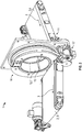
- a scoring machine according to the invention for scoring a surface of an item is shown in Fig. 1 .
- a scoring machine shown in Fig. 1 is an example of a set-up of the scoring machine 1 in which it can directly form part of a slaughter line as a stand-alone machine.
- Frequency converters, a control cabinet and the like are not shown in the Figure, but will form part of the scoring machine 1 in a preferred embodiment.
- the scoring machine 1 has a frame 8 that can naturally be built in very many different shapes according to desire and needs and requirements made of ease of operation, maintenance and cleaning. Additionally, the frame 8 may have a number of wheels to make it easier to manoeuvre the scoring machine 1.
- a transport path 2 is constituted by a first conveyor 4, which is able, in a direction of movement 3 (see Fig. 2 ), to convey items to be scored forwards to the scoring devices 14 (see Fig. 4 ), whereupon a second conveyor 5 is able to move items away from the scoring devices 14, likewise in the same direction of movement 3.
- Fig. 1 also shows a third conveyor 6 having the same direction of movement 3 as the other two conveyors 4, 5.
- the conveyor 6 extends through the hole 10 (see Fig. 4 ) so that at least along a length of the conveyor 6, the conveyor 6 has substantially the same distance from the sides thereof to the first conveyor 4 or the second conveyor 5, i.e. extends in parallel with the first conveyor 4 or the second conveyor.
- the same considerations as already mentioned for the conveyors 4, 5 apply as to the nature of the conveyor 6. Accordingly, the conveyor 6 does not necessarily have the same dimensions as the other conveyors 4, 5.
- the scoring machine 1 comprises a structure 11 having a curved path 7, a number of scoring devices 14 (See Fig. 4 ) being mounted on the structure 11 in such a manner that they are movable along the curved path 7.
- the curved path 7 may be constituted by any structure 11 with a circle or a circular segment constituting a curved path 7 that fits the item to be scored, the curved path 7 having a number of movable scoring devices 14 mounted on it.
- the curved path 7 corresponds to the curvature extending transversely to the main dimension of a loin of a pig, the loin piece being substantially plane in its main dimension and curved transversely to its main dimension, and the structure 11 having a curved path extending transversely to both the transport path 2 and the direction of movement 3 of the item moved.
- the items conveyed have the surface to be scored facing downwards against the first conveyor 4, but in an alternative embodiment, the surface to be scored might face away from the surface of the first conveyor 4, which would thus presuppose that the conveyor 4 was set to convey the item to be scored towards the diagonally opposite side of the curved path 7 and that the conveyors 4, 5 were closer to each other.
- the scoring machine 1 may be operated manually by reciprocating the scoring devices 14 along the curved path 7 or, as is possible in the embodiment shown here where the curved path 7 constitutes a circle, by moving the scoring devices 14 in the same direction all the time and accordingly around the item to be scored.
- conveyor belts which are, for example, smooth, have a non-absorbent surface, are resistant and easy to clean may be used as conveyors 4, 5, but depending on the items to be conveyed and the requirements made of cleaning and hygiene, other conveyors such as modular belts in many different designs may of course also be used.
- the conveyors 4, 5 are straight, but they may of course also be curved if the items to be scored are to be conveyed around a corner, for example.
- the conveyers may have individual dimensions, be made of different materials and run at respective speeds.
- the conveyors 4, 5 are mounted and set for the scoring machine to make the optimum scoring of loin pieces.
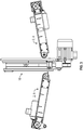
- This setting of the scoring machine 1 appears best from Fig. 3 .
- the first conveyor 4 and the second conveyor 5 need not be symmetrically arranged with respect to the tubular bearing 6, but may preferably be adjustable upwardly and downwardly, as well as possible in inclination. This adjustability makes it possible optimize the conveying of the items along the curved surface 7 to and from the first conveyor 4 and the second conveyor 5, depending on the quality of the items and their mechanical properties, depending in turn on inter alia their temperature.
- the two conveyors 4, 5 can be adjusted and set at any other imaginable position depending on the nature of the item to be scored and depending on its behaviour during scoring.
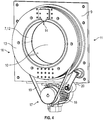
- the structure 11 comprises a bearing in the form of a tubular bearing 16 having an external tubular bearing part 13 and an internal tubular bearing part 12, the internal tubular bearing part 12 having a curved path 7.
- the scoring device 14 is mounted so that it can rotate about the centre line of the tubular bearing parts 12, 13 and transversely to the direction of movement 3 of the item moved.
- the movement may be made manually, but in the preferred embodiment the movement is made by means of a driven mechanism.
- the conveyors 4, 5 may be advantageous to set the conveyors 4, 5 so that their surfaces are not aligned in the same plane, but are set so that the item to be scored is conveyed along what can best be described as a soft curve, whereby the surface of the item becomes slightly flexed outwards, which makes the scoring easier.
- the scoring device 14 is therefore mounted on the end of the external tubular bearing part 13, which faces away from the direction of movement 3 of the item moved.
- the structure makes it possible to reverse the direction of movement 3 of the scoring machine 1 so that the scoring can be made before the item is conveyed to and passes through the tubular bearing 16.
- the scoring machine 1 further comprises a frame 8 with a plate 9, the plate 9 having a hole 10, the internal tubular bearing part 12 being firmly mounted on the plate 9 in such a manner that the hole 10 and the internal tubular bearing part 12 have substantially the same centre line and that the diameter of the hole 10 is at least equal to or larger than the inside diameter of the internal tubular bearing part 12.
- the internal tubular bearing part 12 has a number of guiding devices 15 shown in Fig. 2 .
- These guiding devices 15 may be in the shape of one or more simple side guides to guide the item to be scored through the tubular bearing 16.
- friction-reducing means such as a teflon coating or devices in the form of balls, pins or the like may be placed on parts or the whole of the curved path 7 constituting the contact surface of the tubular bearing 16 with the item to be scored.
- an aggregate guide or guiding device having friction-reducing means may be provided to guide the item to be scored from the first conveyor 4 to the scoring devices 14.
- the internal tubular bearing part 12 has a diameter of 230-310 mm, preferably 250-290 mm, and most preferably 270 mm
- the external tubular bearing part 13 has a diameter of 360-440 mm, preferably 380-420 mm, and most preferably 400 mm
- the tubular bearing 16 has a height of 60-140 mm, preferably 80-120 mm, and most preferably 100 mm.
- This embodiment of a tubular bearing 16 makes it possible for the scoring machine 1 to make the optimum scoring of loin pieces because the curved path 7 of the internal tubular bearing part 12 corresponds to the curvature of the given loin pieces.
- a drive mechanism 17 that may be constituted by a motor 18 mounted on a bracket 20, which may, for example, be mounted on the plate 9, the motor 18 driving the external tubular bearing part 13 by means of a belt 19.
- the motor 18 may, for example, be electrically driven, but other possibilities might be more natural than an electric motor, depending on the situation, such as a pneumatic motor or a hydraulic motor, and the belt 19 may, for example, be a flat belt, a toothed belt, a V-belt or whatever is possible.
- the scoring devices 14 are naturally exposed to contact with the items to be scored, and the scoring devices 14 are thereby subject to wear, and of course there will therefore also be a need to be able to detect when the maximum permissible change in the condition of the scoring devices has occurred, while damage suddenly arisen to the scoring devices 14 has to be addressed immediately.
- detection means not shown in the Figures, in the form of, for example, sensors or light barriers are mounted on the structure 11.
- scoring devices 14 of a ceramic design, but this will again depend on the item to be scored and the materials available.
- the embodiment shown has been made with a particular view to the scoring of portions of a carcass, the portions being loin pieces from pigs having a slaughter weight of between 65 and 110 kg, the loin pieces having an average length of 620 mm and a width of 150-170 mm.
- the loin pieces are without bones and have not been derinded, and after passage through the scoring machine the scored loin piece can thus be sold as a pork roast.
- the scoring machine 1 could score or pre-cut streaky bacon, cutlets or other portions from pigs.
- loin fillets and the like may be of help to consumers who might want to use cheese, herbs, garlic, marinades and the like in their cooking.
Landscapes
- Life Sciences & Earth Sciences (AREA)
- Engineering & Computer Science (AREA)
- Forests & Forestry (AREA)
- Mechanical Engineering (AREA)
- Food Science & Technology (AREA)
- Wood Science & Technology (AREA)
- Zoology (AREA)
- Processing Of Meat And Fish (AREA)
- Structure Of Belt Conveyors (AREA)
- Apparatuses For Bulk Treatment Of Fruits And Vegetables And Apparatuses For Preparing Feeds (AREA)
- Framework For Endless Conveyors (AREA)
- Confectionery (AREA)
Description
- The present invention relates to a scoring machine for scoring a surface of an item which is substantially plane in its main dimension and is curved transversely to its main dimension, the item being moved along a transport path in a direction of movement, such as a surface of an item being conveyed forwards by means of a number of conveyors.
- The present invention also relates to the use of the said scoring machine.
- Before the development of the present invention, it was known to score a surface of an item by means of a manually operated scoring device. Such scoring device might be simply a knife or one or more knife blades joined in a handle. Such manually operated scoring device would thus make it possible to make several simultaneous and parallel scores in the item.
- One of the disadvantages of this scoring work is that it is work causing repetitive strain injury (RSI), that is, work in which the same work operation is repeated at intervals of few seconds or minutes. However, such work may cause large both physical and mental working environment problems and should therefore be avoided.
- Another one of the disadvantages of this work is that it is very slow and will cause the end products to be very non-uniform.
- The industry has therefore also several times experimented with the use of machines for the scoring process to make it semi- or fully automatic. Before the development of the present invention, it was thus known to manually place the items to be scored into a holder, which was a substantially stationary installation, the items being held fast and immovable during the scoring process. Subsequently, the items could then be removed again manually and new items placed in the holder.
- However, one of the disadvantages of this semi-automatic scoring process was also work causing repetitive strain injury in the form of placing items into holders and removing the items. Moreover, these devices also suffered from the disadvantage that, owing to the scoring, the end products may have had the same interval between the scores made, but the scores were made in a very non-uniform manner and did not have the same scoring depth in the surfaces of the items, and as an example, the devices scored through the membrane between skin and flesh, or the devices scored inadequately. This in turn resulted in the need to score the items manually afterwards, which was inexpedient from the point of view of time, manpower and thereby economy.
-
US 6,231,911 B1 concerns a device for superficially incising a sausage-like meat product, such as a hot dog. Described is a device and method for incising a cylindrical shaped meat product in which a motor rotates a tubular shaped cutter housing around the longitudinal axis of the tubular housing. Inclined blades are mounted on the inner surface of the cutter housing. An injector transports the meat product into the rotating cutter housing inlet and an ejector transports the incised meat product from the rotating cutter housing. One of the disadvantages of the hot dog incisor is that it can only make incisions all around the meat product. It is thus not possible to use the incisor when incisions should not be produced all around a meat product. - The object of this invention is therefore to provide a scoring machine of the type mentioned in the introduction which scores the surface of items faster and better than prior-art technology. In any circumstances, it is an object of the invention to provide a scoring machine that scores the surface of items in a uniform manner regardless of the point of time of the working day, uniformity of scoring being of great significance to the perceived quality. In case of, for example, the scoring of a loin, the rind must be scored and cut through across the entire loin in an unbroken cut and so that the scoring does not penetrate membranes and enter the fillet.
- It is a further object of the invention to make it possible to score surfaces of up to 700 items an hour, one item being, for example, a portion of a carcass, such as a loin piece which, with for example an average length of 620 mm and a scoring interval of 10 mm, requires scoring 60 times. Accordingly, the scoring must be carried out while the items are being moved along a transport path in a direction of transportation.
- It is a further object of the invention that the scoring machine is to be hygienic to make it suitable for use on foods, and particularly for arrangement in a cutting line in a slaughterhouse. Additionally, the scoring device must be easy to operate and maintain so that it does not imply an inexpediently large need of staff hours.
- According to an aspect of the invention, the above object is achieved with a scoring machine of the type mentioned in the introduction, the scoring machine comprising a structure with a curved path adapted to have substantially the same curvature as the conveyed item transversely to its main dimension, and a number of scoring devices being mounted in the structure in such a manner that the scoring devices are movable along the curved path extending transversely to both the transport path and the direction of movement of the item moved, the structure comprising a tubular bearing having an internal tubular bearing part with a curved path and an external tubular bearing part, the scoring device being mounted on the external tubular bearing part in such a manner that the scoring device can rotate about the centre line of the tubular bearing parts and transversely to the direction of movement of the item moved by means of a drive mechanism.
- This makes it possible to score the surface of items, for example a portion of a carcass, such as a loin piece, which in fact has a curvature transversely to its main dimension.
- This makes it possible to guide the scoring devices in the same direction transversely to the main dimension of the item to be scored as the scoring devices can thus rotate about the item and do not necessarily have to make a reciprocating movement.
- In a further aspect, the present invention also relates to a scoring machine, the scoring device being mounted on the end of the external tubular bearing part which faces away from the direction of movement of the item moved.
- This makes it possible to score the item when it is moved away from the tubular bearing and not when it is guided into the tubular bearing, thus avoiding a braking effect of the scores during the passage of the tubular bearing.
- In another aspect, the present invention also relates to a scoring machine, the scoring machine further comprising a frame with a plate, the plate having a hole, and the internal tubular bearing part being firmly mounted on the plate in such a manner that the hole and the internal tubular bearing part have substantially the same centre line and that the diameter of the hole is at least equal to or larger than the inside diameter of the internal tubular bearing part.
- This makes it possible to make at least one embodiment of a so-called stand-alone apparatus that can be inserted into a slaughter line instead of, for example, a derinding machine if and when needed.
- In yet a further aspect, the present invention also relates to a scoring machine, the scoring machine comprising a number of conveyors, a first conveyor leading to the side of the structure facing against the direction of movement of the item moved, and a second conveyor leading away from the structure in the direction of movement of the item moved.
- This makes it possible to convey the item to be scored forward to the scoring machine and the scoring devices.
- In a alternative aspect, the present invention also relates to a scoring machine, the scoring machine further comprising a third conveyor extending through the hole and having, along a length thereof, substantially the same distance from the sides to the first conveyor or the second conveyor.
- This makes it possible to convey the item to be scored forwards the whole way through the tubular bearing, the item to be scored moving between two conveyors on the inlet side, between one conveyor and the internal tubular bearing part through the tubular bearing part and between two conveyors on the discharge side.
- In a further aspect, the present invention also relates to a scoring machine, the internal tubular bearing part having a number of guiding devices.
- This makes it possible to guide the item to be scored through the tubular bearing in such a manner that the item does not behave inexpediently in the form of making folds, running askew or making other undesired movements.
- In further aspects, the present invention also relates to a scoring machine, the internal tubular bearing part having a diameter of 230-310 mm, preferably 250-290 mm, and most preferably 270 mm, the external tubular bearing part having a diameter of 360-3440 mm, preferably 380-420 mm, and most preferably 400 mm, and the tubular bearing having a height of 60-140 mm, preferably 80-120 mm, and most preferably 100 mm, respectively.
- This makes it possible to make at least one embodiment that fits the most common items to be scored.
- In another aspects, the present invention also relates to a scoring machine, the drive mechanism comprises a motor mounted on a bracket on the plate, the motor driving the external tubular bearing part by means of a belt, the belt comprising a flat belt, a toothed belt or a V-belt.
- This makes it possible to carry out the scoring automatically at the same speed and scoring rate, whereby the scoring becomes much more uniform than at manual scoring.
- In another aspect, the present invention also relates to a scoring machine, the scoring machine further having detection means in the form of, for example, sensors or light barriers.
- When the detection means are set at, for example, the scoring devices, this makes it possible to stop the machine as soon as a change in the condition of the scoring devices is detected, such as a pre-set wear threshold or damage suddenly arisen during production.
- In an alternative aspect, the present invention also relates to a scoring machine, the scoring devices comprise ceramic scoring devices.
- This makes it possible to uphold a longer life and minimise the tendency for the scoring devices to break.
- In another aspect, the present invention also relates to the use of a scoring machine for scoring portions of a carcass, the portions being, for example, loin pieces.
- Accordingly, this makes it possible to score the surface of items in a uniform manner regardless of the point of time of the working day, of surfaces of up to 700 items an hour and in a hygienic manner.
- The invention will be described in further detail below by means of non-limiting embodiments with reference to the drawing, in which:
- Fig. 1
- shows a perspective view of the scoring machine;
- Fig. 2
- shows a perspective view of the structure and two conveyors;
- Fig. 3
- shows a side view of the structure and two conveyors; and
- Fig. 4
- shows a perspective view of the structure with tubular bearing and drive mechanism.
- A scoring machine according to the invention for scoring a surface of an item is shown in
Fig. 1 . - The embodiment of a scoring machine shown in
Fig. 1 is an example of a set-up of the scoringmachine 1 in which it can directly form part of a slaughter line as a stand-alone machine. Frequency converters, a control cabinet and the like are not shown in the Figure, but will form part of the scoringmachine 1 in a preferred embodiment. - The scoring
machine 1 has aframe 8 that can naturally be built in very many different shapes according to desire and needs and requirements made of ease of operation, maintenance and cleaning. Additionally, theframe 8 may have a number of wheels to make it easier to manoeuvre thescoring machine 1. - As appears from the embodiment shown in
Fig. 1 , a transport path 2 is constituted by a first conveyor 4, which is able, in a direction of movement 3 (seeFig. 2 ), to convey items to be scored forwards to the scoring devices 14 (seeFig. 4 ), whereupon a second conveyor 5 is able to move items away from the scoringdevices 14, likewise in the same direction ofmovement 3. -
Fig. 1 also shows athird conveyor 6 having the same direction ofmovement 3 as the other two conveyors 4, 5. Theconveyor 6 extends through the hole 10 (seeFig. 4 ) so that at least along a length of theconveyor 6, theconveyor 6 has substantially the same distance from the sides thereof to the first conveyor 4 or the second conveyor 5, i.e. extends in parallel with the first conveyor 4 or the second conveyor. In all other respects, the same considerations as already mentioned for the conveyors 4, 5 apply as to the nature of theconveyor 6. Accordingly, theconveyor 6 does not necessarily have the same dimensions as the other conveyors 4, 5. - As appears from
Fig. 2 , the scoringmachine 1 comprises astructure 11 having a curved path 7, a number of scoring devices 14 (SeeFig. 4 ) being mounted on thestructure 11 in such a manner that they are movable along the curved path 7. The curved path 7 may be constituted by anystructure 11 with a circle or a circular segment constituting a curved path 7 that fits the item to be scored, the curved path 7 having a number ofmovable scoring devices 14 mounted on it. - In the embodiment shown, the curved path 7 corresponds to the curvature extending transversely to the main dimension of a loin of a pig, the loin piece being substantially plane in its main dimension and curved transversely to its main dimension, and the
structure 11 having a curved path extending transversely to both the transport path 2 and the direction ofmovement 3 of the item moved. - In a preferred embodiment, the items conveyed have the surface to be scored facing downwards against the first conveyor 4, but in an alternative embodiment, the surface to be scored might face away from the surface of the first conveyor 4, which would thus presuppose that the conveyor 4 was set to convey the item to be scored towards the diagonally opposite side of the curved path 7 and that the conveyors 4, 5 were closer to each other.
- The scoring
machine 1 may be operated manually by reciprocating thescoring devices 14 along the curved path 7 or, as is possible in the embodiment shown here where the curved path 7 constitutes a circle, by moving thescoring devices 14 in the same direction all the time and accordingly around the item to be scored. - Conventional endless conveyor belts which are, for example, smooth, have a non-absorbent surface, are resistant and easy to clean may be used as conveyors 4, 5, but depending on the items to be conveyed and the requirements made of cleaning and hygiene, other conveyors such as modular belts in many different designs may of course also be used.
- In a preferred embodiment, the conveyors 4, 5 are straight, but they may of course also be curved if the items to be scored are to be conveyed around a corner, for example. Moreover, the conveyers may have individual dimensions, be made of different materials and run at respective speeds.
- In the embodiment shown in
Figs. 1 ,2 and3 , the conveyors 4, 5 are mounted and set for the scoring machine to make the optimum scoring of loin pieces. Experiments have shown that it is advantageous to set the conveyors 4, 5 so that their surfaces are not aligned in the same plane, but are set so that the item to be scored is conveyed along what can best be described as a soft curve, whereby the surface of the item becomes slightly flexed outwards, which makes the scoring easier. This setting of the scoringmachine 1 appears best fromFig. 3 . As also apparent fromFig. 3 the first conveyor 4 and the second conveyor 5 need not be symmetrically arranged with respect to thetubular bearing 6, but may preferably be adjustable upwardly and downwardly, as well as possible in inclination. This adjustability makes it possible optimize the conveying of the items along the curved surface 7 to and from the first conveyor 4 and the second conveyor 5, depending on the quality of the items and their mechanical properties, depending in turn on inter alia their temperature. - Of course, it will also be obvious to a worker skilled in the art that the two conveyors 4, 5 can be adjusted and set at any other imaginable position depending on the nature of the item to be scored and depending on its behaviour during scoring.
- As appears from
Fig. 4 , thestructure 11 comprises a bearing in the form of atubular bearing 16 having an externaltubular bearing part 13 and an internal tubular bearing part 12, the internal tubular bearing part 12 having a curved path 7. On the externaltubular bearing part 13, the scoringdevice 14 is mounted so that it can rotate about the centre line of thetubular bearing parts 12, 13 and transversely to the direction ofmovement 3 of the item moved. The movement may be made manually, but in the preferred embodiment the movement is made by means of a driven mechanism. - As described above, it may be advantageous to set the conveyors 4, 5 so that their surfaces are not aligned in the same plane, but are set so that the item to be scored is conveyed along what can best be described as a soft curve, whereby the surface of the item becomes slightly flexed outwards, which makes the scoring easier. In the preferred embodiment, the scoring
device 14 is therefore mounted on the end of the externaltubular bearing part 13, which faces away from the direction ofmovement 3 of the item moved. - However, the structure makes it possible to reverse the direction of
movement 3 of the scoringmachine 1 so that the scoring can be made before the item is conveyed to and passes through thetubular bearing 16. - According to the embodiment shown, the scoring
machine 1 further comprises aframe 8 with a plate 9, the plate 9 having ahole 10, the internal tubular bearing part 12 being firmly mounted on the plate 9 in such a manner that thehole 10 and the internal tubular bearing part 12 have substantially the same centre line and that the diameter of thehole 10 is at least equal to or larger than the inside diameter of the internal tubular bearing part 12. - In the preferred embodiment, the internal tubular bearing part 12 has a number of guiding
devices 15 shown inFig. 2 . These guidingdevices 15 may be in the shape of one or more simple side guides to guide the item to be scored through thetubular bearing 16. - Also, friction-reducing means such as a teflon coating or devices in the form of balls, pins or the like may be placed on parts or the whole of the curved path 7 constituting the contact surface of the tubular bearing 16 with the item to be scored.
- Alternatively, an aggregate guide or guiding device having friction-reducing means may be provided to guide the item to be scored from the first conveyor 4 to the
scoring devices 14. - In a preferred embodiment, the internal tubular bearing part 12 has a diameter of 230-310 mm, preferably 250-290 mm, and most preferably 270 mm, while the external
tubular bearing part 13 has a diameter of 360-440 mm, preferably 380-420 mm, and most preferably 400 mm, and thetubular bearing 16 has a height of 60-140 mm, preferably 80-120 mm, and most preferably 100 mm. - This embodiment of a
tubular bearing 16 makes it possible for the scoringmachine 1 to make the optimum scoring of loin pieces because the curved path 7 of the internal tubular bearing part 12 corresponds to the curvature of the given loin pieces. - That the
structure 11 can be moved manually by reciprocating thescoring devices 14 along the curved path 7 or, as is possible in the embodiment shown here, by moving thescoring devices 14 in the same direction all the time and accordingly around the item to be scored is certainly a possibility, but it is endeavoured to use adrive mechanism 17 that may be constituted by amotor 18 mounted on abracket 20, which may, for example, be mounted on the plate 9, themotor 18 driving the externaltubular bearing part 13 by means of abelt 19. - The
motor 18 may, for example, be electrically driven, but other possibilities might be more natural than an electric motor, depending on the situation, such as a pneumatic motor or a hydraulic motor, and thebelt 19 may, for example, be a flat belt, a toothed belt, a V-belt or whatever is possible. - The scoring
devices 14 are naturally exposed to contact with the items to be scored, and thescoring devices 14 are thereby subject to wear, and of course there will therefore also be a need to be able to detect when the maximum permissible change in the condition of the scoring devices has occurred, while damage suddenly arisen to thescoring devices 14 has to be addressed immediately. In a preferred embodiment of the invention, detection means, not shown in the Figures, in the form of, for example, sensors or light barriers are mounted on thestructure 11. - To minimise the risk of damage suddenly occurring to the
scoring devices 14, it will therefore be expedient to use scoringdevices 14 of a ceramic design, but this will again depend on the item to be scored and the materials available. - The embodiment shown has been made with a particular view to the scoring of portions of a carcass, the portions being loin pieces from pigs having a slaughter weight of between 65 and 110 kg, the loin pieces having an average length of 620 mm and a width of 150-170 mm. The loin pieces are without bones and have not been derinded, and after passage through the scoring machine the scored loin piece can thus be sold as a pork roast.
- However, there are many other possibilities when using the
scoring machine 1 according to the invention as, with a different setting of the scoring rate, the scoringmachine 1 could score or pre-cut streaky bacon, cutlets or other portions from pigs. - Likewise, scoring in loin pieces without a rind, loin fillets and the like may be of help to consumers who might want to use cheese, herbs, garlic, marinades and the like in their cooking.
- If two
structures 11 are set up in continuation of each other so that the items to be scored pass through both thestructures 11 through transport path 2 and if thestructures 11 are angled so that the distance between them is smaller on one side of the transport path 2 than on the other, it is thus possible to make scores in two directions constituting squares in the surface of the items to be scored. - For a worker skilled in the art, there will certainly also be a number of tasks outside the food industry for which a scoring by means of this invention will be usable, and the invention is thus not limited to the food industry.
- In the drawing, the following reference numerals have been used for the designations used in the detailed part of the description:
- 1
- scoring machine
- 2
- transport path
- 3
- direction of movement
- 4
- first conveyor (inlet)
- 5
- second conveyor (discharge)
- 6
- third conveyor
- 7
- curved path
- 8
- frame
- 9
- plate
- 10
- hole
- 11
- structure
- 12
- internal tubular bearing part
- 13
- external tubular bearing part
- 14
- scoring device
- 15
- guiding device
- 16
- tubular bearing
- 17
- drive mechanism
- 18
- motor
- 19
- belt
- 20
- bracket
Claims (15)
- A scoring machine (1) for scoring a surface of an item which is substantially plane in its main dimension and is curved transversely to its main dimension, the item being moved along a transport path (2) in a direction of movement (3), such as a surface of an item being conveyed forwards by means of a number of conveyors (4,5,6), the scoring machine (1) comprises a structure (11) with a curved path (7) adapted to have substantially the same curvature as the conveyed item transversely to its main dimension, and a number of scoring devices (14) being mounted on the structure (11) in such a manner that the scoring devices (14) are movable along the curved path (7) extending transversely to both the transport path (2) and the direction of movement (3) of the item moved, characterized in that the structure (11) comprises a tubular bearing (16) having an internal tubular bearing part (12) with a curved path (7) and an external tubular bearing part (13), the scoring device (14) being mounted on the external tubular bearing part (13) in such a manner that the scoring device (14) can rotate about the centre line of the tubular bearing parts (12, 13) and transversely to the direction of movement (3) of the item moved by means of a drive mechanism (17).
- A scoring machine (1) according to claim 1, characterized in that the scoring device (14) is mounted on the end of the external tubular bearing part (13) which faces away from the direction of movement (3) of the item moved.
- A scoring machine (1) according to claims 1 to 2, characterized in that the scoring machine (1) further comprises a frame (8) with a plate (9), the plate (9) having a hole (10), the internal tubular bearing part (12) being firmly mounted on the plate (9) in such a manner that the hole (10) and the internal tubular bearing part (12) have substantially the same centre line and that the diameter of the hole (10) is at least equal to or larger than the inside diameter of the internal tubular bearing part (12).
- A scoring machine (1) according to claims 1 to 3, characterized in that the scoring machine (1) comprises a number of conveyors, a first conveyor (4) leading to the side of the structure (11) facing against the direction of movement (3) of the item moved, and a second conveyor (5) leading away from the structure (11) in the direction of movement (3) of the item moved.
- A scoring machine (1) according to claim 4, characterized in that the scoring machine (1) further comprises a third conveyor (6) extending through the hole (10) and having, along a length thereof, substantially the same distance from the sides to the first conveyor (4) or the second conveyor (5).
- A scoring machine (1) according to claims 2 to 5, characterized in that a number of guiding devices (15) are provided in the internal tubular bearing part (12).
- A scoring machine (1) according to any one of claims 2-6, characterized in that the internal tubular bearing part (12) has a diameter of 230-310 mm, preferably 250-290 mm, and most preferably 270 mm.
- A scoring machine (1) according to any one of claims 2 to 7, characterized in that the external tubular bearing part (13) has a diameter of 360-440 mm, preferably 380-420 mm, and most preferably 400 mm.
- A scoring machine (1) according to any one of claims 2 to 8, characterized in that the tubular bearing (16) has a height of 60-140 mm, preferably 80-120 mm, and most preferably 100 mm.
- A scoring machine (1) according to any one of claims 2 to 9, characterized in that the drive mechanism (17) comprises a motor (18) mounted on a bracket (20) on the plate (9), the motor (18) driving the external tubular bearing part (13) by means of a belt (19).
- A scoring machine (1) according to claim 10, characterized in that the belt (19) comprises, a flat belt, a toothed belt or a V-belt.
- A scoring machine (1) according to any one of claims 1 to 11, characterized in that the scoring machine (1) further has detection means in the form of, for example, sensors or light barriers.
- A scoring machine (1) according to claims 1 to 12, characterized in that the number of the scoring devices (14) comprise ceramic scoring devices (14).
- A scoring machine (1) according to claims 4 to 13, characterized in that the first conveyor (4) and the second conveyor (5) are adjustable upwardly and downwardly as well as in inclination.
- The use of a scoring machine (1) according to any one of claims 1 to 14 for scoring portions of a carcass, the portions being, for example, loin pieces.
Applications Claiming Priority (1)
| Application Number | Priority Date | Filing Date | Title |
|---|---|---|---|
| DKPA201200338A DK177350B1 (en) | 2012-05-14 | 2012-05-14 | scratch machine |
Publications (3)
| Publication Number | Publication Date |
|---|---|
| EP2664240A2 EP2664240A2 (en) | 2013-11-20 |
| EP2664240A3 EP2664240A3 (en) | 2015-11-25 |
| EP2664240B1 true EP2664240B1 (en) | 2016-12-07 |
Family
ID=58802975
Family Applications (1)
| Application Number | Title | Priority Date | Filing Date |
|---|---|---|---|
| EP13166039.1A Active EP2664240B1 (en) | 2012-05-14 | 2013-04-30 | A scoring machine |
Country Status (4)
| Country | Link |
|---|---|
| US (1) | US8753178B2 (en) |
| EP (1) | EP2664240B1 (en) |
| DK (2) | DK177350B1 (en) |
| ES (1) | ES2615528T3 (en) |
Family Cites Families (19)
| Publication number | Priority date | Publication date | Assignee | Title |
|---|---|---|---|---|
| US2216216A (en) | 1936-07-21 | 1940-10-01 | Cube Steak Machine Company Inc | Meat-slitting machine |
| US2675580A (en) * | 1950-11-09 | 1954-04-20 | Pesce Augustine Franklin | Hot dog knife |
| US2981971A (en) * | 1959-07-06 | 1961-05-02 | Zubrychi Theodore | Sausage slitters |
| US3099307A (en) | 1961-03-02 | 1963-07-30 | Hillen J Morgan | Meat scoring and trimming knife |
| US3902388A (en) | 1974-01-18 | 1975-09-02 | Robert C New | Frankfurter skin slitter |
| US4442761A (en) * | 1980-09-23 | 1984-04-17 | Elsie Palmieri | Apparatus for making pastry products |
| US4524894A (en) * | 1982-12-29 | 1985-06-25 | Gerber Garment Technology, Inc. | Method and apparatus for forming pattern pieces |
| EP0223794B1 (en) * | 1985-06-05 | 1990-12-05 | Tendapak Technologies Pty. Limited | Apparatus for the production of processed meat products |
| IL76450A0 (en) * | 1985-09-22 | 1986-01-31 | Israel State | Apparatus and method for husking corn |
| US4873746A (en) * | 1988-01-25 | 1989-10-17 | Simon-Johnson Company | Method and apparatus for removing breast meat from poultry carcass |
| US5331874A (en) * | 1991-10-16 | 1994-07-26 | Universal Frozen Foods, Inc | Cutting apparatus |
| DK172769B1 (en) * | 1996-02-20 | 1999-07-12 | Slagteriernes Forskningsinst | Knife and tool in machine for cutting along thorn pins in a carcass or carcass part |
| US5746106A (en) * | 1997-01-15 | 1998-05-05 | Hodges; Ralph S. | High volume meat product incisor |
| DE29820100U1 (en) | 1998-11-10 | 1999-02-11 | Große, Hartmut, 06193 Nauendorf | Cutting device for cutting the surfaces of meat, meat products or the like. |
| US6368647B1 (en) * | 1998-12-29 | 2002-04-09 | Mars, Incorporated | Ultrasonically activated continuous slitter apparatus and method |
| IT1305285B1 (en) * | 1999-01-18 | 2001-05-04 | Refin Srl | DEVICE FOR PORTIONING GROUND MEAT FOR PACKAGING TIN OR SIMILAR. |
| US6231911B1 (en) * | 1999-10-29 | 2001-05-15 | Clarence Steinback | Ultra high speed hot dog incisor |
| DE10125737A1 (en) * | 2001-05-16 | 2002-11-21 | Schill Maja Masch | Two-sided meat or fish de-skinning assembly has first de-skinning wheel linked to second de-skinning wheel by inversion belt |
| DE102009033725A1 (en) * | 2009-07-17 | 2011-03-24 | Vemag Maschinenbau Gmbh | Method and device for producing sausages |
-
2012
- 2012-05-14 DK DKPA201200338A patent/DK177350B1/en not_active IP Right Cessation
-
2013
- 2013-04-30 EP EP13166039.1A patent/EP2664240B1/en active Active
- 2013-04-30 DK DK13166039.1T patent/DK2664240T3/en active
- 2013-04-30 ES ES13166039.1T patent/ES2615528T3/en active Active
- 2013-05-02 US US13/875,740 patent/US8753178B2/en not_active Expired - Fee Related
Non-Patent Citations (1)
| Title |
|---|
| None * |
Also Published As
| Publication number | Publication date |
|---|---|
| US20130303063A1 (en) | 2013-11-14 |
| DK2664240T3 (en) | 2017-03-06 |
| DK177350B1 (en) | 2013-02-11 |
| ES2615528T3 (en) | 2017-06-07 |
| EP2664240A3 (en) | 2015-11-25 |
| US8753178B2 (en) | 2014-06-17 |
| EP2664240A2 (en) | 2013-11-20 |
Similar Documents
| Publication | Publication Date | Title |
|---|---|---|
| US3731344A (en) | In-feed for automatic cut-up saw | |
| KR101243979B1 (en) | The flash meat, fish and skate slice method that used the slope and space gap of the blade | |
| EP0223794B1 (en) | Apparatus for the production of processed meat products | |
| MX2012012076A (en) | Tuna skinning machine. | |
| US3675272A (en) | Method of cutting and packing poultry | |
| US8753178B2 (en) | Scoring machine | |
| US9730461B1 (en) | Multiple-level skinning apparatus | |
| US10555539B2 (en) | Cutting device and a cutting system for cutting food products | |
| US3631908A (en) | Automatic meat-cutting machine | |
| US3662430A (en) | Splitting machine for chicken | |
| GB2480480A (en) | Food carving apparatus | |
| CN220903476U (en) | Conveying device for slicing machine and slicing machine | |
| KR20150032047A (en) | Fish fillet machine | |
| DK9600164U3 (en) | Machine for portion cutting especially foods | |
| JP5313546B2 (en) | Cutting equipment for stick food raw wood | |
| JP2016209948A (en) | Method and apparatus for manufacturing die-shaped food product | |
| US20220408740A1 (en) | A slaughtered pig part processing plant with a pig part deskinner, and a slaughtered pig part deskinner unit | |
| WO1991009531A1 (en) | Method and apparatus for slicing meat | |
| USRE28077E (en) | Automatic heat cutting machine | |
| US20240284921A1 (en) | Peeling machine and relative method for peeling stuffed food products | |
| JP2010239885A (en) | Device for removing string-like connecting portions of chain-like food having string-like connecting portions | |
| EP1377171B1 (en) | A device for skinning poultry parts | |
| GB2361619A (en) | Method and apparatus for conveying and separating of sausages or the like | |
| RU2168899C2 (en) | Fish carcass filleting apparatus | |
| EP1284100B1 (en) | An automatic skinner for smoothskinned seafood. |
Legal Events
| Date | Code | Title | Description |
|---|---|---|---|
| PUAI | Public reference made under article 153(3) epc to a published international application that has entered the european phase |
Free format text: ORIGINAL CODE: 0009012 |
|
| AK | Designated contracting states |
Kind code of ref document: A2 Designated state(s): AL AT BE BG CH CY CZ DE DK EE ES FI FR GB GR HR HU IE IS IT LI LT LU LV MC MK MT NL NO PL PT RO RS SE SI SK SM TR |
|
| AX | Request for extension of the european patent |
Extension state: BA ME |
|
| PUAL | Search report despatched |
Free format text: ORIGINAL CODE: 0009013 |
|
| AK | Designated contracting states |
Kind code of ref document: A3 Designated state(s): AL AT BE BG CH CY CZ DE DK EE ES FI FR GB GR HR HU IE IS IT LI LT LU LV MC MK MT NL NO PL PT RO RS SE SI SK SM TR |
|
| AX | Request for extension of the european patent |
Extension state: BA ME |
|
| RIC1 | Information provided on ipc code assigned before grant |
Ipc: B26D 3/08 20060101ALI20151016BHEP Ipc: B26D 1/43 20060101ALI20151016BHEP Ipc: B26D 1/00 20060101ALI20151016BHEP Ipc: A22B 5/16 20060101ALI20151016BHEP Ipc: A22C 17/12 20060101AFI20151016BHEP Ipc: B26D 5/32 20060101ALI20151016BHEP Ipc: B26D 1/26 20060101ALI20151016BHEP Ipc: B26D 7/06 20060101ALI20151016BHEP |
|
| 17P | Request for examination filed |
Effective date: 20160504 |
|
| RBV | Designated contracting states (corrected) |
Designated state(s): AL AT BE BG CH CY CZ DE DK EE ES FI FR GB GR HR HU IE IS IT LI LT LU LV MC MK MT NL NO PL PT RO RS SE SI SK SM TR |
|
| GRAP | Despatch of communication of intention to grant a patent |
Free format text: ORIGINAL CODE: EPIDOSNIGR1 |
|
| INTG | Intention to grant announced |
Effective date: 20160921 |
|
| GRAS | Grant fee paid |
Free format text: ORIGINAL CODE: EPIDOSNIGR3 |
|
| GRAA | (expected) grant |
Free format text: ORIGINAL CODE: 0009210 |
|
| AK | Designated contracting states |
Kind code of ref document: B1 Designated state(s): AL AT BE BG CH CY CZ DE DK EE ES FI FR GB GR HR HU IE IS IT LI LT LU LV MC MK MT NL NO PL PT RO RS SE SI SK SM TR |
|
| REG | Reference to a national code |
Ref country code: GB Ref legal event code: FG4D |
|
| REG | Reference to a national code |
Ref country code: CH Ref legal event code: EP Ref country code: AT Ref legal event code: REF Ref document number: 850921 Country of ref document: AT Kind code of ref document: T Effective date: 20161215 |
|
| REG | Reference to a national code |
Ref country code: IE Ref legal event code: FG4D |
|
| REG | Reference to a national code |
Ref country code: DE Ref legal event code: R096 Ref document number: 602013014942 Country of ref document: DE |
|
| PG25 | Lapsed in a contracting state [announced via postgrant information from national office to epo] |
Ref country code: LV Free format text: LAPSE BECAUSE OF FAILURE TO SUBMIT A TRANSLATION OF THE DESCRIPTION OR TO PAY THE FEE WITHIN THE PRESCRIBED TIME-LIMIT Effective date: 20161207 |
|
| REG | Reference to a national code |
Ref country code: DK Ref legal event code: T3 Effective date: 20170301 |
|
| REG | Reference to a national code |
Ref country code: NL Ref legal event code: FP |
|
| REG | Reference to a national code |
Ref country code: SE Ref legal event code: TRGR |
|
| REG | Reference to a national code |
Ref country code: LT Ref legal event code: MG4D |
|
| REG | Reference to a national code |
Ref country code: FR Ref legal event code: PLFP Year of fee payment: 5 |
|
| PG25 | Lapsed in a contracting state [announced via postgrant information from national office to epo] |
Ref country code: LT Free format text: LAPSE BECAUSE OF FAILURE TO SUBMIT A TRANSLATION OF THE DESCRIPTION OR TO PAY THE FEE WITHIN THE PRESCRIBED TIME-LIMIT Effective date: 20161207 Ref country code: GR Free format text: LAPSE BECAUSE OF FAILURE TO SUBMIT A TRANSLATION OF THE DESCRIPTION OR TO PAY THE FEE WITHIN THE PRESCRIBED TIME-LIMIT Effective date: 20170308 |
|
| REG | Reference to a national code |
Ref country code: NO Ref legal event code: T2 Effective date: 20161207 |
|
| REG | Reference to a national code |
Ref country code: AT Ref legal event code: MK05 Ref document number: 850921 Country of ref document: AT Kind code of ref document: T Effective date: 20161207 |
|
| PG25 | Lapsed in a contracting state [announced via postgrant information from national office to epo] |
Ref country code: HR Free format text: LAPSE BECAUSE OF FAILURE TO SUBMIT A TRANSLATION OF THE DESCRIPTION OR TO PAY THE FEE WITHIN THE PRESCRIBED TIME-LIMIT Effective date: 20161207 Ref country code: RS Free format text: LAPSE BECAUSE OF FAILURE TO SUBMIT A TRANSLATION OF THE DESCRIPTION OR TO PAY THE FEE WITHIN THE PRESCRIBED TIME-LIMIT Effective date: 20161207 |
|
| REG | Reference to a national code |
Ref country code: ES Ref legal event code: FG2A Ref document number: 2615528 Country of ref document: ES Kind code of ref document: T3 Effective date: 20170607 |
|
| PG25 | Lapsed in a contracting state [announced via postgrant information from national office to epo] |
Ref country code: CZ Free format text: LAPSE BECAUSE OF FAILURE TO SUBMIT A TRANSLATION OF THE DESCRIPTION OR TO PAY THE FEE WITHIN THE PRESCRIBED TIME-LIMIT Effective date: 20161207 Ref country code: EE Free format text: LAPSE BECAUSE OF FAILURE TO SUBMIT A TRANSLATION OF THE DESCRIPTION OR TO PAY THE FEE WITHIN THE PRESCRIBED TIME-LIMIT Effective date: 20161207 Ref country code: IS Free format text: LAPSE BECAUSE OF FAILURE TO SUBMIT A TRANSLATION OF THE DESCRIPTION OR TO PAY THE FEE WITHIN THE PRESCRIBED TIME-LIMIT Effective date: 20170407 Ref country code: RO Free format text: LAPSE BECAUSE OF FAILURE TO SUBMIT A TRANSLATION OF THE DESCRIPTION OR TO PAY THE FEE WITHIN THE PRESCRIBED TIME-LIMIT Effective date: 20161207 Ref country code: SK Free format text: LAPSE BECAUSE OF FAILURE TO SUBMIT A TRANSLATION OF THE DESCRIPTION OR TO PAY THE FEE WITHIN THE PRESCRIBED TIME-LIMIT Effective date: 20161207 |
|
| PG25 | Lapsed in a contracting state [announced via postgrant information from national office to epo] |
Ref country code: AT Free format text: LAPSE BECAUSE OF FAILURE TO SUBMIT A TRANSLATION OF THE DESCRIPTION OR TO PAY THE FEE WITHIN THE PRESCRIBED TIME-LIMIT Effective date: 20161207 Ref country code: PT Free format text: LAPSE BECAUSE OF FAILURE TO SUBMIT A TRANSLATION OF THE DESCRIPTION OR TO PAY THE FEE WITHIN THE PRESCRIBED TIME-LIMIT Effective date: 20170407 Ref country code: PL Free format text: LAPSE BECAUSE OF FAILURE TO SUBMIT A TRANSLATION OF THE DESCRIPTION OR TO PAY THE FEE WITHIN THE PRESCRIBED TIME-LIMIT Effective date: 20161207 Ref country code: BG Free format text: LAPSE BECAUSE OF FAILURE TO SUBMIT A TRANSLATION OF THE DESCRIPTION OR TO PAY THE FEE WITHIN THE PRESCRIBED TIME-LIMIT Effective date: 20170307 Ref country code: SM Free format text: LAPSE BECAUSE OF FAILURE TO SUBMIT A TRANSLATION OF THE DESCRIPTION OR TO PAY THE FEE WITHIN THE PRESCRIBED TIME-LIMIT Effective date: 20161207 Ref country code: IT Free format text: LAPSE BECAUSE OF FAILURE TO SUBMIT A TRANSLATION OF THE DESCRIPTION OR TO PAY THE FEE WITHIN THE PRESCRIBED TIME-LIMIT Effective date: 20161207 |
|
| REG | Reference to a national code |
Ref country code: DE Ref legal event code: R097 Ref document number: 602013014942 Country of ref document: DE |
|
| PLBE | No opposition filed within time limit |
Free format text: ORIGINAL CODE: 0009261 |
|
| STAA | Information on the status of an ep patent application or granted ep patent |
Free format text: STATUS: NO OPPOSITION FILED WITHIN TIME LIMIT |
|
| 26N | No opposition filed |
Effective date: 20170908 |
|
| PG25 | Lapsed in a contracting state [announced via postgrant information from national office to epo] |
Ref country code: SI Free format text: LAPSE BECAUSE OF FAILURE TO SUBMIT A TRANSLATION OF THE DESCRIPTION OR TO PAY THE FEE WITHIN THE PRESCRIBED TIME-LIMIT Effective date: 20161207 |
|
| REG | Reference to a national code |
Ref country code: CH Ref legal event code: PL |
|
| PG25 | Lapsed in a contracting state [announced via postgrant information from national office to epo] |
Ref country code: MC Free format text: LAPSE BECAUSE OF FAILURE TO SUBMIT A TRANSLATION OF THE DESCRIPTION OR TO PAY THE FEE WITHIN THE PRESCRIBED TIME-LIMIT Effective date: 20161207 |
|
| PG25 | Lapsed in a contracting state [announced via postgrant information from national office to epo] |
Ref country code: LI Free format text: LAPSE BECAUSE OF NON-PAYMENT OF DUE FEES Effective date: 20170430 Ref country code: CH Free format text: LAPSE BECAUSE OF NON-PAYMENT OF DUE FEES Effective date: 20170430 Ref country code: LU Free format text: LAPSE BECAUSE OF NON-PAYMENT OF DUE FEES Effective date: 20170430 |
|
| REG | Reference to a national code |
Ref country code: FR Ref legal event code: PLFP Year of fee payment: 6 |
|
| PG25 | Lapsed in a contracting state [announced via postgrant information from national office to epo] |
Ref country code: MT Free format text: LAPSE BECAUSE OF NON-PAYMENT OF DUE FEES Effective date: 20170430 |
|
| PG25 | Lapsed in a contracting state [announced via postgrant information from national office to epo] |
Ref country code: HU Free format text: LAPSE BECAUSE OF FAILURE TO SUBMIT A TRANSLATION OF THE DESCRIPTION OR TO PAY THE FEE WITHIN THE PRESCRIBED TIME-LIMIT; INVALID AB INITIO Effective date: 20130430 |
|
| PG25 | Lapsed in a contracting state [announced via postgrant information from national office to epo] |
Ref country code: CY Free format text: LAPSE BECAUSE OF NON-PAYMENT OF DUE FEES Effective date: 20161207 |
|
| PG25 | Lapsed in a contracting state [announced via postgrant information from national office to epo] |
Ref country code: MK Free format text: LAPSE BECAUSE OF FAILURE TO SUBMIT A TRANSLATION OF THE DESCRIPTION OR TO PAY THE FEE WITHIN THE PRESCRIBED TIME-LIMIT Effective date: 20161207 |
|
| PG25 | Lapsed in a contracting state [announced via postgrant information from national office to epo] |
Ref country code: TR Free format text: LAPSE BECAUSE OF FAILURE TO SUBMIT A TRANSLATION OF THE DESCRIPTION OR TO PAY THE FEE WITHIN THE PRESCRIBED TIME-LIMIT Effective date: 20161207 |
|
| PG25 | Lapsed in a contracting state [announced via postgrant information from national office to epo] |
Ref country code: AL Free format text: LAPSE BECAUSE OF FAILURE TO SUBMIT A TRANSLATION OF THE DESCRIPTION OR TO PAY THE FEE WITHIN THE PRESCRIBED TIME-LIMIT Effective date: 20161207 |
|
| PGFP | Annual fee paid to national office [announced via postgrant information from national office to epo] |
Ref country code: NO Payment date: 20200422 Year of fee payment: 8 Ref country code: IE Payment date: 20200420 Year of fee payment: 8 Ref country code: FI Payment date: 20200421 Year of fee payment: 8 |
|
| PGFP | Annual fee paid to national office [announced via postgrant information from national office to epo] |
Ref country code: SE Payment date: 20200427 Year of fee payment: 8 Ref country code: BE Payment date: 20200427 Year of fee payment: 8 |
|
| REG | Reference to a national code |
Ref country code: FI Ref legal event code: MAE |
|
| REG | Reference to a national code |
Ref country code: NO Ref legal event code: MMEP |
|
| REG | Reference to a national code |
Ref country code: SE Ref legal event code: EUG |
|
| REG | Reference to a national code |
Ref country code: BE Ref legal event code: MM Effective date: 20210430 |
|
| PG25 | Lapsed in a contracting state [announced via postgrant information from national office to epo] |
Ref country code: NO Free format text: LAPSE BECAUSE OF NON-PAYMENT OF DUE FEES Effective date: 20210430 Ref country code: FI Free format text: LAPSE BECAUSE OF NON-PAYMENT OF DUE FEES Effective date: 20210430 Ref country code: SE Free format text: LAPSE BECAUSE OF NON-PAYMENT OF DUE FEES Effective date: 20210501 |
|
| PG25 | Lapsed in a contracting state [announced via postgrant information from national office to epo] |
Ref country code: IE Free format text: LAPSE BECAUSE OF NON-PAYMENT OF DUE FEES Effective date: 20210430 |
|
| PG25 | Lapsed in a contracting state [announced via postgrant information from national office to epo] |
Ref country code: BE Free format text: LAPSE BECAUSE OF NON-PAYMENT OF DUE FEES Effective date: 20210430 |
|
| PGFP | Annual fee paid to national office [announced via postgrant information from national office to epo] |
Ref country code: NL Payment date: 20250418 Year of fee payment: 13 |
|
| PGFP | Annual fee paid to national office [announced via postgrant information from national office to epo] |
Ref country code: DE Payment date: 20250422 Year of fee payment: 13 |
|
| PGFP | Annual fee paid to national office [announced via postgrant information from national office to epo] |
Ref country code: GB Payment date: 20250423 Year of fee payment: 13 Ref country code: ES Payment date: 20250529 Year of fee payment: 13 Ref country code: DK Payment date: 20250429 Year of fee payment: 13 |
|
| PGFP | Annual fee paid to national office [announced via postgrant information from national office to epo] |
Ref country code: FR Payment date: 20250425 Year of fee payment: 13 |